1
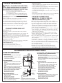
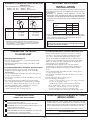
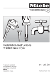
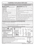
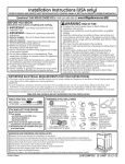
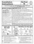
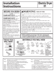
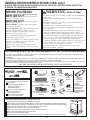
INSTALLATION INSTRUCTIONS (USA only)
MODELS DSKS433 AND DSKS333 MUST BE INSTALLED WITH CONTROL PANEL AT BOTTOM
IN ORDER TO OPERATE ADEQUATELY.
BEFORE YOU BEGIN
Read these instructions completely and carefully.
• IMPORTANT- Save these instructions for local inspector’s use.
• IMPORTANT- Observe all governingcodes and ordinances.
• Note to Installer - Be sure to leave these instructions with the customer.
• Note to Customer - Keep these instructions with
your Use and Care Book for future reference.
• Before the old dryer is removed from service or
discarded, remove the dryer door.
• Service information and the wiring diagram are
located in the control console.
• Do not allow children on or in the appliance. Close
supervision of children is necessary when the
appliance is used near children.
• Install the dryer where the temperature is above
50°F for satisfactory operation of the dryer control
system.
WARNING
RISK OF FIRE
• To reduce the risk of severe injury or death, follow all installation
instructions.
• Clothes dryer installation must be performed by a qualified
installer.
• Install the clothes dryer according to these instructions and in
accordance with local codes.
• This dryer must be exhausted to the outdoors.
• Use only 4” rigid metal ducting for exhausting the clothes dryer
to the outdoors.
• DO NOT install a clothes dryer with flexible plastic ducting
materials. If flexible metal (semi-rigid or foil-type) duct is
installed, it must be UL listed and installed in accordance with
the instructions found in "Connecting The Dryer To House
Vent" on page 4 of this manual. Flexible venting materials are
known to collapse, be easily crushed, and trap lint. These
conditions will obstruct dryer airflow and increase the risk of fire.
• Do not install or store this appliance in any location where it
could be exposed to water and or weather.
• Save these instructions. (Installers: Be sure to leave these
instructions with the customer).
DETERMINE ELECTRICAL REQUIREMENTS FOR YOUR DRYER MODEL
• This dryer must be connected to an individual branch circuit of proper voltage and frequency as specified on Rating Plate (located inside dryer
door) with no other appliances or fixtures attached.
EXCEPTION:
• A 120V receptacle is located on the back on the dryer and is available only for use with a washer that is affixed to the dryer with a WDF-85 kit. It may
not be used for any other appliance or any conditions other than slated above (208 & 240V models only).
• Branch circuit must be protected by the required time-delay fuses or circuit brackers 208V or 240V installation - 30 amps 120V installation 15 or 20 amps.
• The electrical installation must conform to the national and local codes.
208V AND 240V MODELS ARE NOT APPROVED FOR120 V INSTALLATION.
TOOLS YOU WILL NEED
SLIP JOINT PLIERS
FLAT BLADE SCREWDRIVER
PHILLIPS SCREWDRIVER
STACKING KITS FOR DRYERS
(comes with individual installation instructions)
Over washer
- Use Wall Mount Kit WMK-35 or
- Stack Rack DSDR24 or
- Stack Rack DSR-24
For alcove and closet depth and
width requirements see
specific kit instructions
All stacking kits are available
from your local sales outlet.
MATERIALS YOU WILL NEED
4" DIA. METAL DUCT
(RECOMMENDED)
4" DUCT
CLAMPS (2)
OR
4" SPRING
4" DIA. FLEXIBLE METAL (SEMI-RIGID)
CLAMPS (2)
UL LISTED TRANSITION DUCT
(IF NEEDED)
KIT WX08X10077 (INCLUDES 2 ELBOWS)
4" DIA. FLEXIBLE METAL (FOIL TYPE)
UL LISTED TRANSITION DUCT
(IF NEEDED.)
UNPACKING AND PREPARING FOR INSTALLATION
4" DIA. METAL
ELBOW
SAFETY
GLASSES
EXHAUST
HOOD
3/4" STRAIN
RELIEF
UL RECOGNIZED
DUCT TAPE
GLOVES
Prepare the area and exhaust for installation of new dryer.
Check and ensure the existing external exhaust is clean and meets attached installation specifications.
Remove the literature and accesories bag from the dryer drum. Place the literature in a convenient place.
Using foam pads from dryer carton, turn dryer upside down as shown.
Install knobs. For location, refer to “Use and Care” Book.
Dryer is now ready to be mounted above washer using accessory kit.
Remove the foam shipping pads from under dryer.
Move the dryer to the desired location.
Follow the steps in the following pages to connect the dryer to the external exhaust and power supply.
PAGE 1
DRYER POWER
CORD KIT
(NOT PROVIDED
WITH DRYER)
UL RATED
120/240V,30A
WITH 3 OR 4 PRONGS.
IDENTIFY THE PLUG
TYPE AS PER THE
HOUSE RECEPTACLE
BEFORE PURCHASING
LINE CORD.
ELECTRICAL CONNECTION DETAILS
OBSERVE ALL GOVERNING CODES AND ORDINANCES
GROUNDING INSTRUCTIONS
The operating voltage (Volts), Amperage (Amps) and Frequency
(Hz) of this dryer are indicated on the Rating Plate located to the
right of the loading port.
Connect this dryer to a circuit corresponding to that indicated on
rating plate and protected by fuses or a circuit breaker
in accordance with local codes.
Use a power supply cord kit marked for use with clothes dryer.
For 208V and 240V models, use a power supply cord kit marked for use
with clothes dryers.
This appliance must be grounded. In the event of malfunction or
breakdown, grounding will reduce the risk of electric shock by providing
a path of least resistance for electrical current.
WARNING: Improper connection of the equipment grounding conductor
can result in a risk of electric shock. Check with a qualified electrician
or serviceman if you are in doubt as to whether the appliance is
properly grounded.
Do not modify the plug provided with the appliance - if it will not fit the
outlet, have a proper outlet installed by a qualified electrician.
DO NOT USE EXTENSION CORD WITH THIS APPLIANCE
For alternate 208V or 240V power supply hook-up, proceed as follows:
Remove rear access panel.
Connect supply wire leads to terminal block as shown on sketch below, depending on type of installation.
WARNING: Appliance grounded to neutral conductor through a link. If used in a mobile home or if local codes do not permit grounding through neutral, a
4-conductor cord or cable assembly for use with clothes dryers must be used with the following specifications: Type St. Cable, 125/250 Min Volt, 30 Amp
with closed-loop terminals and secured with a UL recognized strain relief. See manufacturer’s instructions
Make sure screws on terminal block are tight.
FOR THREE-WIRE SUPPLY
FOR FOUR-WIRE SUPPLY
Connect two (2) HOT lines to outer screws (L1 and L2) of terminal block.
Connect Neutral line to center screw (N) of terminal block.
Remove ground strap and discard. Rescrew green grounding screw in
place.
Connect two (2) HOT lines to outer screws (L1 and L2) of terminal block.
Connect NEUTRAL line to center screw (N) of terminal block.
Attach ground wire of power supply to green grounding screw beside
terminal block.
(208V & 240V MODELS)
POWER SUPPLY CORD 3#10
AWG MINIMUM COPPER
CONDUCTORS
30 AMP, 240V, WITH
TYPE UL RECOGNIZED
MINIMUM RATED 90°C
REAR
HOT WIRE
HOT WIRE
GREEN
GROUNDING
SCREW
WHITE
NEUTRAL
WIRE
GROUND
STRAP
L 1
N
208V or 240V
FRONT
REAR
GREEN OR YELLOW
GROUND WIRE
HOT WIRE
GREEN
GROUNDING
SCREW
208 OR 240
VOLT OPERATION
120/208 OR 120/240
VOLT SUPPLY
(USE ONLY
30 AMP FUSES)
L 2
(208V & 240V MODELS)
WHITE
NEUTRAL
WIRE
HOT WIRE
L 1
N
L 2
208V or 240V
FRONT
INSIDE TOP VIEW OF DRYER
POWER SUPPLY CORD 4 #10
AWG MINIMUM COPPER
CONDUCTORS, 30 AMP, 240V,
WITH CLOSED-LOOP TERMINALS
TYPE UL RECOGNIZED MINIMUM
RATED 90°C.
REMOVE GROUND
STRAP AND DISCARD
208 OR 240
VOLT OPERATION
120/208 OR 120/240
VOLT SUPPLY
(USE ONLY
30 AMP FUSES)
FOR PERSONAL SAFETY, THIS APPLIANCE MUST BE
PROPERLY GROUNDED.
FOR PERSONAL SAFETY, THIS APPLIANCE MUST BE
PROPERLY GROUNDED.
Properly strain relief the cord set or cable to the cable entry hole with
UL recognized strain relief.
Make sure cordset or the cable is away from the rotating drum.
Replace access panel.
Properly strain relief the cord set or cable to the cable entry hole with
UL recognized strain relief.
Make sure cordset or the cable is away from the rotating drum.
Replace access panel.
X
3 WIRE RECEPTACLE
(10-30R)
G
W
Y
Typical 30 amp receptacle for use where
local codes permit use of flexible type
power supply cord (pigtail).
4-WIRE RECEPTACLE
(14-30R)
Typical 30 amp receptacle for use
where local codes permit use of
flexible type power supply
cord (pigtail).
PAGE 2
4-CONDUCTOR CORD
ASSEMBLY ( Type ST Cable)
Typical 30 amp cord assembly for
use where local codes do not
permit grounding through
neutral.
EXHAUST INFORMATION
SEALING OF JOINTS
• All joints should be tight to avoid leaks. The male end of each section of
duct must point away from the dryer.
• Do not assemble the ductwork with fasteners that extend into the duct.
They will serve as a collection point for lint.
• Duct joints can be made air and moisture-tight by wrapping the
overlapped joints with duct tape.
• Horizontal runs should slope down toward the outdoors ½ inch per foot
WARNING - IN CANADA AND IN THE UNITED
STATES, THE REQUIRED EXHAUST DUCT DIAMETER
IS 4 IN (102mm). DO NOT USE DUCT LONGER
THAN SPECIFIED IN THE EXHAUST LENGTH TABLE.
Using exhaust longer than specified length will:
• Increase the drying times and the energy cost.
• Reduce the dryer life.
• Accumulate lint, creating a potential fire hazard.
The correct exhaust installation is YOUR RESPONSIBILITY.
Problems due to incorrect installation are not covered
by the warranty.
Remove and discard existing plastic or metal foil transition
duct and replace with UL listed transition duct.
INSULATION
Duct work that runs through an unheated area or is near air conditioning
should be insulated to reduce condensation and lint build-up.
EXHAUST CONNECTION
WARNING - TO REDUCE THE RISK
OF FIRE OR PERSONAL INJURY:
• This clothes dryer must be exhausted to the outdoors.
• Use only 4” rigid metal ducting for the home exhaust duct.
• Use only 4” rigid metal or UL-listed flexible metal (semirigid or foil-type) duct to connect the dryer to the home
exhaust duct. It must be installed in accordance with the
instructions found in “Connecting The Dryer To House
Vent” on page 4 of this manual.
• Do not terminate exhaust in a chimney, a wall, a ceiling, gas
vent, crawl space, attic, under an enclosed floor, or in any
other concealed space of a building. The accumulated lint
could create a fire hazard.
• Never terminate the exhaust into a common duct with a
kitchen exhaust system. A combination of grease and lint
creates a potential fire hazard.
• Do not use duct longer than specified in the exhaust length
table. Longer ducts can accumulate lint, creating a potential fire hazard.
• Never install a screen in or over the exhaust duct. This will
cause lint to accumulate, creating a potential fire hazard.
• Do not assemble ductwork with any fasteners that extend
into the duct. These fasteners can accumulate lint, creating
a potential fire hazard.
• Do not obstruct incoming or exhausted air.
• Provide an access for inspection and cleaning of the
exhaust system, especially at turns and joints. Exhaust
system shall be inspected and cleaned at least once a year.
The MAXIMUM ALLOWABLE duct length and number of
bends of the exhaust system depends upon the type of duct,
number of turns, the type of exhaust hood (wall cap), and all
conditions noted below. The maximum duct length for rigid
metal duct is shown in the table on the next page.
EXHAUST SYSTEM CHECK LIST
HOOD OR WALL CAP
• Terminate in a manner to prevent back drafts or entry of birds or
other wildlife.
• Termination should present minimal resistance to the exhaust air flow
and should require little or no maintenance to prevent clogging.
• Never install a screen in or over the exhaust duct.This could cause lint build up.
• Wall caps must be installed at least 12 in. above ground level or any other
obstruction with the opening pointed down.
SEPARATION OF TURNS
For best performance, separate all turns by at least 4 ft. of straight duct,
including distance between last turn and exhaust hood.
TURNS OTHER THAN 90º
• One turn of 45º or less may be ignored.
• Two 45º turns should be treated as one 90º turn.
• Each turn over 45º should be treated as one 90º turn.
ALTERNATE EXHAUST DIRECTIONS
152 mm
6”
Left knockout
203 mm
(8”)
Blower
Front of dryer
IF YOUR DRYER COMES WITH REAR
EXHAUST, TO CHANGE TO SIDE OR
DOWN EXHAUST:
Remove access panel at back of dryer to gain
access to internal ducts.
Disconnect duct exhaust from blower housing
(remove tape securing duct).
FOR SIDE EXHAUST:
Remove desired knockout plate (either right or
left side).
Cut a 115 mm (4 ½”) length of 100 mm (4”) dia
rigid duct as shown (remove burrs from cut
edge).
Right knockout
Attach this extension duct to blower housing duct.
Attach a 90° elbow facing desired opening.
Attach a section of 100 mm (4”) dia, rigid duct to
295 mm (11½”)
elbow to protrude through side of cabinet.
115 mm (4½”)
Seal all joints with duct tape.
Reinstall rear acces panel.
FOR BOTTOM EXHAUST:
Remove cover plate at bottom of dryer.
Install a 90° elbow.
Seal all joints with duct tape.
Reinstall rear access panel.
Place cover plate (removed from bottom of
dryer) over rear exhaust opening.
Bottom
knockout
89 mm
(3½”)
For Rear Exhaust
For Side Exhaust
Cut Here
EXTENSION DUCT
Rigid
Metallic
Ducting
IF YOUR DRYER COMES WITH TOP EXHAUSTING,
TO CHANGE TO SIDE OR REAR EXHAUST:
Remove rear access panel.
Disconnect retaining plate & 90° elbow by removing
mounting screw from the chassis & remove tape securing
elbow to blower hounsing.
Remove cover plate from rear access panel and place over
top exhaust opening.
FOR SIDE EXHAUST:
Remove desired knockout plate (either right or left
side).
Cut a 115 mm (4 ½ “) lenght of 100 mm (4”) dia, rigid
duct as shown (remove burrs from cut edge).
Attach this extension duct to blower housing duct.
Attach the 90° elbow facing desired opening.
Attach a section of 100 mm (4”) dia, rigid duct to
elbow to protude thru side of cabinet.
Seal all joints with duct tape.
Reinstall rear access panel.
FOR REAR EXHAUST:
Cut a 295 mm (11 ½ “) length of 100 mm (4”) dia, rigid
duct as shown (remove burrs from cutting edge).
Attach this extension duct to blower housing.
Seal all joints with duct tape.
Reinstall near access panel.
It is importat to replace the ground clip after
cutting the exhaust duct, (on rear exhaust model).
PAGE 3
ALCOVE OR CLOSET
INSTALLATION
EXHAUST LENGTH CALCULATION
RIGID (Preferred)
Parts are available from your local service organization:
WX8X63 4”X1’ Duct
WX8X51 Elbow
WX8X64 4”X2’ Duct
WX8X59 Aluminum hood
RECOMMENDED MAXIMUM LENGTH
Exhaust Hood Types
Use only for short
Recommended
run installations
4" DIA.
4" DIA.
4"
No. of 90º
Elbows
0
1
2
3
If your dryer is approved for installation in an alcove or closet, it will be stated on a label on the dryer back. The installation must conform to the following specifications;
WARNING: TO PREVENT LARGE AMOUNTS OF LINT AND
MOISTURE FROM ACCUMULATING AND TO MAINTAIN DRYER
EFFICIENCY, THIS MACHINE MUST BE EXHAUSTED OUTDOORS.
Minimum clearances between dryer cabinet and adjacent walls or other
surfaces are:
2-1/2"
Rigid
Metal
Rigid
Metal
14 m (46 ft)
11 m (38 ft)
9 m (31 ft)
7 m (24 ft)
11 m (37 ft)
9 m (30 ft)
6.5 m (22 ft)
4.5 m (15 ft)
FLEXIBLE
RIGID METAL TRANSITION DUCT
• For best drying performance, a rigid metal transition
duct is recommended.
• Rigid metal transitions ducts reduce the risk of crushing and kinking.
UL-LISTED FLEXIBLE METAL (SEMI-RIGID) TRANSITION DUCT
• If rigid metal duct cannot be used, then UL-listed
flexible metal (semi-rigid) ducting can be used (Kit
WX08X10077).
• Never install flexible metal duct in walls, ceilings, floors
or other enclosed spaces.
• Total length of flexible metal duct should not exceed 8
feet (2.4m).
• For many applications, installing elbows at both the
dryer and the wall is highly recommended (see illustrations below). Elbows allow the dryer to sit close to the
wall without kinking and or crushing the transition
duct, maximizing drying performance.
• Avoid resting the duct on sharp objects.
Closet
1”
Top
1”
1”
Front
-
3“
Rear
3”
3”
Closet doors must be louvered or otherwise ventilated and must contain
at least 60 square inches of area equally distributed. If this closet contains
both a washer and a dryer, doors must contain at least 120 square
inches of open area equally distributed.
Total length of flexible metal duct shall not exceed 8 ft (2.4 m).
The following kit is available from you local service organization:
Kit WX08X10077 - 4” dia. flexible metal (semi-rigid) UL-listed
transition duct (includes 2 elbows).
CONNECTING THE DRYER
TO HOUSE VENT
Alcove
0”
Sides
NOTE: The clearances stated above are minimums. Consideration
must be given to the type accessory kit used with dryer. Refer to
the specific kit instruction for details.
UL-LISTED FLEXIBLE METAL (FOIL-TYPE) TRANSITION DUCT
• In special installations, it may be necessary to connect
the dryer to the house vent using a flexible metal (foiltype) duct. A UL-listed flexible metal (foil-type)duct
may be used ONLY in installations where rigid metal or
flexible metal (semi-rigid) ducting cannot be used AND
where a 4" diameter can be maintained throughout the
entire length of the transition duct.
• In Canada and the United States, only the flexible
metal(foil-type) ducts that comply with the “Outline for
Clothes Dryer Transition Duct Subject 2158A” shall be
used.
• Never install flexible metal duct in walls, ceilings, floors
or other enclosed spaces.
• Total length of flexible metal duct should not exceed 8
feet (2.4m).
• Avoid resting the duct on sharp objects.
• For best drying performance:
1. Slide one end of the duct over the clothes dryer outlet pipe.
2. Secure the duct with a clamp.
3. With the dryer in its permanent position, extend the
duct to its full length. Allow 2” of duct to overlap the
exhaust pipe. Cut off and remove excess duct. Keep
the duct as straight as possible for maximum airflow.
4. Secure the duct to the exhaust pipe with the other clamp.
NOTE TO INSTALLER ...AFTER INSTALLATION
CHECK THE FOLLOWING
WHEN INSTALLED IN MANUFACTURED
(MOBILE) HOMES Dryer must be exhausted to the outside. Exhaust MUST NOT be terminated
beneath mobile home. Exhaust material MUST NOT support combustion.
Installation MUST conform to Manufactured Home Construction & Safety
Standard, Title 24 CFR, Part 32-80 or when such standard is not applicable, the
American National Standard of Mobile Homes, ANSI/NFRA No. 501B-1977.
EXHAUST DUCT - must meet specs on Page 3. No excessive turns.
No kinks or obstructions to air flow.
EXHAUST HOOD - should work freely and open downward.
GROUNDING - Dryer must be properly grounded to conform to local
codes and ordinance requirements.
OPERATION - turn dryer on and check for heat.
HAND CUSTOMER THE USE AND CARE BOOK - Give instructions
on operating the dryer - answer any questions.
GIVE THESE INSTALLATION INSTRUCTIONS to the customer.
For electrical connection, see “Connecting dryer using 4 wire connection”.
USE OF CASTERS
(120V PORTABLE MODELS ONLY)
For a portable installation screw casters into the holes on the bottom of the dryer. Refer to the “Installation Instructions for
caster assembly” sheet to install casters.
PAGE 4
322B3166P001
pub # 31-16233