1
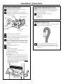
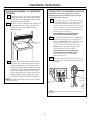
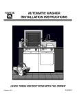
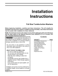
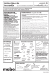
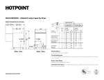
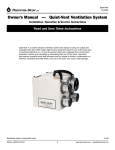
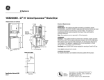
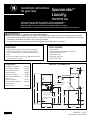
Installation instructions
for your new
Spacemaker™
Laundry
WSM2780 Gas
Before you begin – Read these instructions completely and carefully.
IMPORTANT – OBSERVE ALL GOVERNING CODES AND ORDINANCES.
Note to Installer – Be sure to leave these instructions with the Consumer.
Note to Consumer – Keep these instructions with your Owner’s Manual for future reference.
WARNING –
POTENTIAL FIRE AND SHOCK HAZARD
• Use only rigid metal or flexible metal 4″ diameter ductwork inside the dryer cabinet or for exhausting to the outside.
Use of plastic or other combustible ductwork can cause a fire. Foil or other easily punctured ductwork can cause a fire
if it collapses or becomes restricted in use or during installation.
• This appliance must be properly grounded and installed as described in these instructions.
IMPORTANT
TOOLS NEEDED
• Exhausting the dryer to the outside is required to
prevent large amounts of moisture, lint and other
products of combustion from being blown into the
room.
• Service information and a wiring diagram are located
in the dryer access panel.
•
•
•
•
•
•
CONTENTS
PRODUCT DIMENSIONS
Installation Procedure . . . . . . . .page 2
Plumbing Information . . . . . . . .page 5
Electrical Information . . . . . . . . .page 5
Gas Information . . . . . . . . . . . . .page 6
Exhaust Information . . . . . . . . . .page 6
Mobile Home Installation . . . . .page 7
Alcove or
Closet Installation . . . . . . . . . . . .page 7
Door Ventilation Opening . . . . .page 8
Miscellaneous
Requirements . . . . . . . . . . . . . . . .page 8
Slip joint pliers
Phillips-head and flat-blade screwdrivers
Ratchet with 3/8″ socket
Carpenter’s level
Adjustable wrenches
Pipe thread sealer
251⁄ 4″
21⁄ 2″
47″
161⁄ 4″
Gas supply
pipe (rear)
93⁄ 8″
Vent
731⁄ 2″
51°
51⁄ 4″
545⁄ 16″
Water
inlets (rear)
7
Drain outlet 29 ⁄ 16″
(rear)
17⁄ 8″
43″
41 ⁄ ″
14
413⁄ 16″
361⁄ 16″
33⁄ 4″
27″
49-90331
09-07 JR
117⁄ 16″
3013⁄ 16″
134923400 (0907)
Printed in the United States
Installation Instructions
UNPACKING SPACEMAKER™
1 Remove tape and two corner pads from rear
2
bottom corners of appliance.
Using the four shipping corner posts, lay the
appliance on its left side so the shipping base does
not rest on the floor.
Plastic spacer
block
Shipping
blocks
Foam
shipping pad
5
6
7
spacer should be retained for use if the appliance is
transported at a later date.
8 Remove clips holding the following:
a. inlet hoses
b. drain hose
c. power cord
Shipping Rear vent
clips
only
Mechanism
shipping bolt
3
4
UNPACKING SPACEMAKER™ (CONT.)
NOTE: The tub blocking pad, shipping bolt and plastic
PREPARING DRAIN HOSE
9 Form a “U” shape on the end of the drain hose with
Drain hose
the hose pointed toward the drain.
Shipping carton
corner posts
Remove the foam shipping pad.
Remove the washer shipping bolt using the ratchet
with 3/8″ socket and remove the plastic spacer
block using the slip joint pliers.
Return the appliance to the upright position and
locate it in the general area to be installed. Provide
enough space at the rear for installing the water
inlet hose.
Untape and open washer lid.
10
Remove:
a. foam tub blocking pad
b. foam shipping blocks from rear of unit
c. tape from dryer door
d. foam dryer support pads
e. inlet hoses
f. From the back of the washer, remove the wire
shipping clips securing the drain hose. Plastic
clamps secure the drain hose to the right side
of the washer backsheet. These clamps form a
standpipe to prevent water siphoning. DO NOT
REMOVE THESE CLAMPS.
Tub
blocking pad
Dryer
support pads
2
For an installation requiring a longer drain hose,
use the WH41X312 extra-long (108″) drain hose.
Attach to the machine in the same manner as the
original hose.
Installation Instructions
MOVING SPACEMAKER™ TO OPERATING
LOCATION
11 Remove the 2 screws securing the access panel
11A
CONNECTING TO PLUMBING FACILITIES
CAUTION: Be sure water supply lines have been
thoroughly flushed to remove particles that might
clog the washer filter screens.
to the dryer cabinet. Lift the front access panel
until the tabs can be disengaged from the dryer
cabinet and remove the panel.
Route the inlet hoses, drain hose and power cord
through the rear access area for temporary
holding when moving the appliance to the
operating location.
13
Check inlet hoses to insure the rubber washers
are installed in each end. (If your laundry center
has the hoses attached to the water valve,
proceed to Step 13A.) Carefully connect the inlet
hoses to the water valve (on the left side of the
washer cabinet), tighten by hand, then tighten
another 2/3 turn with pliers.
CAUTION: DO NOT CROSS THREAD OR
OVERTIGHTEN THESE CONNECTIONS.
13A
Determine which water faucet is the HOT water
faucet and carefully connect the bottom inlet
hose to the HOT water faucet, tighten by hand,
then tighten another 2/3 turn with pliers.
Carefully connect the top inlet hose to the
COLD water faucet, tighten by hand, then
tighten another 2/3 turn with pliers.
CAUTION: DO NOT CROSS THREAD OR
OVERTIGHTEN THESE CONNECTIONS.
Turn the water on and check for leaks
at both connections.
13B
Place formed end of drain hose in drain facility
and secure with cable tie (provided in literature
package).
Access panel
screws
12
To ensure the Laundry Center is level and solid
on all four legs, tilt the Laundry Center forward
so the rear legs are off the floor. Gently set the
Laundry Center back down to allow the rear legs
to self adjust. Place a level on top of the washer.
Check it side to side, then front to back. Screw
the front leveling legs up or down to ensure the
Laundry Center is resting solid on all four legs
(no rocking of the Laundry Center should exist).
Cable tie
NOTE: Keep the leg extension at a minimum to prevent
Cable tie
excessive vibration.
Cord length
4 ft.
33″ Min./
96″ Max.
NOTE: Drain hose MUST be secured to drain facility in
all cases.
3
Installation Instructions
CONNECTING TO GAS SUPPLY
14 Connect the gas supply to the dryer. If codes
CHECKING APPLIANCE OPERATION
16 Make sure all packing and shipping materials are
allow, use new flexible metal tubing (design
certified by the American Gas Association). Be
sure there are no kinks. For gas connections, you
MUST use pipe joint compound resistant to the
action of LP gas.
CAUTION: Be sure electricity is OFF at power
supply source (circuit breaker/fuse box).
14A
removed, including the washer shipping bolt and
plastic spacer block.
17
Make sure the drain hose is properly routed—not
coiled or kinked.
17A
Make sure water inlet hoses are connected (HOT
to HOT) and tightened securely without kinks.
Turn on water faucets and check for leaks.
17B
Tape all joints to make sure exhaust ductwork is
secured without leaks.
17C
17D
Turn on electricity at the power source.
Plug power cord into electrical outlet.
IMPORTANT: 120 volt 60 hz AC only electrical supply is
required on a separate 15 ampere circuit fused by a time
delay fuse or circuit breaker.
NOTE: Do not, under
any circumstances,
remove grounding
prong from plug.
Turn on the washer and dryer and run through
one cycle. Check all hoses for leaks. Ensure the
burner has lit.
NOTE: Before the burner will light, it is necessary for
the gas line to be bled of air. If the burner does not light
within 45 seconds the first time the dryer is turned on,
the safety switch will shut off the burner. If this happens,
turn the timer to “OFF” and wait 5 minutes before
making another attempt to light.
Grounding
prong
REPLACING FRONT ACCESS PANEL
18 Reinstall the safety cover and front access panel.
19 Place the Owner’s Manual and Installation
FINAL APPLIANCE LEVELING
Instructions in a location where they can be found
by the customer.
CAUTION: ALL WEIGHT MUST BE REMOVED FROM
APPLIANCE LEVELING LEG WHILE ADJUSTING.
THREADS ON LEG WILL BE DAMAGED OTHERWISE.
15
Again, make sure the appliance rests firmly on
all four legs. No rocking of the appliance should
exist.
4
Installation Instructions
PLUMBING INFORMATION
ELECTRICAL CONNECTION
INFORMATION
WATER SUPPLY REQUIREMENTS
CAUTION:
For personal safety:
TURN OFF ELECTRICITY AT POWER SOURCE (CIRCUIT
BREAKER/FUSE BOX) BEFORE INSTALLING OR
SERVICING THIS APPLIANCE.
• HOT AND COLD WATER FAUCETS – Must be within 42″
of the appliance water inlet hose connections. The
faucets must be 3/4″ garden hose-type so inlet
hoses can be connected.
• WATER PRESSURE – Must be between 10 and 120
pounds per square inch with a maximum unbalance
pressure, hot vs cold flowing, of 10 pounds per
square inch.
DO NOT USE AN EXTENSION CORD WITH THIS
APPLIANCE.
THIS APPLIANCE MUST BE PROPERLY GROUNDED.
• SHUT-OFF VALVES – Both hot and cold water shut-off
valves (faucets) should be supplied.
This appliance must be electrically grounded in
accordance with local codes and ordinances, or
in the absence of local codes, in accordance with the
NATIONAL ELECTRICAL CODE, ANSI/NFPA NO. 70-1987.
• LOCATION – Do not install appliance in an area where
the temperature will fall below freezing. If appliance is
stored or transported in freezing temperatures, be sure
all water from the fill and drain systems has been
removed.
ELECTRICAL REQUIREMENTS
• This appliance should be connected to an individual
branch circuit with 120 volt single-phase 60 Hz
electrical service and should be protected by 15 amp.
time-delay fuses or circuit breakers.
DRAIN REQUIREMENTS
• DRAIN RATE – The drain or standpipe must be capable
of accepting a discharge at the rate of 16 gallons per
minute.
• DRAIN HEIGHT – The drain height must be 33″
minimum and 96″ maximum.
• STANDPIPE DIAMETER – The standpipe diameter must
be 1″ minimum. There MUST be an air gap around the
drain hose in the standpipe. A snug fit can cause a
siphoning action.
• SIPHON BREAK KIT – For a drain facility less than 33″
high, the hose, coupling and clamps provided in the
machine must be used and, in addition, a siphon break
MUST be installed on the back of the machine. Use
Siphon Break Kit WH49X228 and FOLLOW
INSTRUCTIONS IN THE KIT.
5
Installation Instructions
GAS CONNECTION INFORMATION
EXHAUST
CAUTION:
Do not attempt to alter gas orifice or adjust burner air
shutter. Natural gas input may vary in some areas from
700 to 1200 B.T.U. per cubic foot. If the gas orifice or
burner air shutter is incorrectly adjusted, serious
personal injury and/or fire hazard can occur. Your local
gas company will know the qualities of the gas in your
area. Contact your local servicing dealer if burner
adjustment or orifice changes are necessary.
Do not use an open flame for leak testing. Serious
personal injury and/or a fire hazard can result if an open
flame is used to test for gas leaks. Use a soap and water
solution to test all gas line fittings.
Do not install the Laundry Center to an L.P. gas supply
without installing conversion kit. All Laundry Centers
are shipped with a pressure regulator and natural gas
orifice. Using a natural gas orifice with an L.P. gas supply
can result in personal injury, clothes damage and/or a
fire hazard. Have a qualified gas technician install a
conversion kit in the Laundry Center before use.
• Installation must meet American National Standard,
National Fuel Gas Code ANSI Z 223 1—1988 and local
codes and ordinances.
EXHAUST DUCT LENGTH INFORMATION
• The MAXIMUM ALLOWABLE length of the exhaust
system depends upon the type of duct, number of
turns, the type of exhaust hood (wall cap) and all
conditions noted below. The maximum allowable length
for both rigid and flexible metal is shown in the table
below. More than three 90° turns are not
recommended.
Rear vent only
NUMBER
OF 90°
TURNS
EXHAUST
HOOD TYPE
A
B
A
B
4″
21⁄ 2″
0
1
2
3
46 ft.
38 ft.
31 ft.
24 ft.
37 ft.
30 ft.
22 ft.
15 ft.
Maximum length of 4″
diameter rigid metal duct
0
1
2
3
30 ft.
25 ft.
20 ft.
16 ft.
24 ft.
20 ft.
14 ft.
10 ft.
Maximum length of 4″
diameter flexible metal
duct
• The gas supply line should be a 1/2″ pipe. A 1/2″ to
3/8″ reducer must be used to connect the dryer to
the supply line.
HOOD OR WALL CAP
• The gas supply line must have a shut-off valve
preferably within six feet of the dryer.
• Terminate in a manner to prevent back drafts or entry
of birds or other wildlife.
• A 1/8″ NPT plugged tapping, accessible for test gauge
connection, must be installed immediately upstream
of the gas supply connection.
• Termination should present minimal resistance to
the exhaust airflow and should require little or no
maintenance to prevent clogging.
• Never install a screen over the exhaust duct.
• Wall caps must be installed at least 12″ above
ground level or any other obstruction with the
opening pointed down.
• If roof vents or louvered plenums are used, they must
be equivalent to a 4″ dampered wall cap in regard to
resistance to airflow, prevention of back drafts and
maintenance required to prevent clogging.
TURNS OTHER THAN 90°
• One turn of 45° or less may be ignored.
• Two 45° turns should be treated as one 90°.
6
Installation Instructions
EXHAUST (CONT.)
MOBILE HOME INSTALLATION
SEALING OF JOINTS
• Installation must conform to Manufactured Home
Construction and Safety Standard, Title 24 CFR,
Part 32-80.
• All joints should be tight to avoid leaks.
NOTE: The male end of each section of duct must point
away from the dryer.
• The dryer must be exhausted to the outside with
the termination securely fastened to the mobile
home structure.
• Do not assemble ductwork with fasteners that
extend into the duct. They will serve as a collection
point for lint.
• The exhaust MUST NOT be terminated beneath the
mobile home.
• Duct joints can be made air- and moisture-tight by
wrapping the overlapped joints with duct tape.
• The exhaust duct material MUST NOT support
combustion.
INSULATION
CONSIDERATION MUST BE GIVEN TO PROVIDE ADEQUATE
CLEARANCES FOR INSTALLATION AND SERVICE.
• Ductwork that runs through an unheated area or is
near an air conditioning duct should be insulated to
reduce condensation and lint buildup.
ALCOVE OR CLOSET INSTALLATION
PARTS AVAILABLE FROM LOCAL SERVICE
ORGANIZATIONS
1″
0″
0″
• Rigid Metal Duct Components
WX8X63
WX8X64
WX8X51
WX8X59
0″
1″
4″ x 1′ Duct
4″ x 2′ Duct
4″ Elbow
4″ Aluminum Hood
60 Sq. In.
• Flexible Metal Duct Components
Kit WX8X66—7′ Aluminum duct, 4″ hood and 2 clamps
WX8X65
7′ Aluminum Flexible Duct
WX8X58
4″ Clamps (2)
WX8X59
4″ Aluminum Hood
60 Sq. In.
• If your dryer is approved for installation in an alcove
or closet, it will be stated on a label on the back of
the dryer.
• TO PREVENT LARGE AMOUNTS OF LINT AND MOISTURE
FROM ACCUMULATING AND TO MAINTAIN DRYING
EFFICIENCY, THIS MACHINE MUST BE EXHAUSTED
OUTDOORS.
• DO NOT install this appliance with less than
the minimum clearances shown above.
CONSIDERATION MUST BE GIVEN TO PROVIDE ADEQUATE
CLEARANCES FOR INSTALLATION AND SERVICE.
CAUTION: DO NOT INSTALL THIS APPLIANCE IN A CLOSET
WITH A SOLID DOOR.
7
Installation Instructions
MISCELLANEOUS REQUIREMENTS
WARNING –
LOCATION
For your safety, the information in this manual must
be followed to minimize the risk of fire or explosion or to
prevent property damage, personal injury or loss of life.
• Do not store or use gasoline or other flammable vapors
and liquids in the vicinity of this or any other appliance.
• WHAT TO DO IF YOU SMELL GAS
• Do not try to light any appliance.
• Do not touch any electrical switch; do not use any
phone in your building.
• Clear the room, building or area of all occupants.
• Immediately call your gas supplier from a neighbor’s
phone. Follow the gas supplier’s instructions.
• If you cannot reach your gas supplier, call the fire
department.
Installation and service must be performed by a qualified
installer, a service agency or the gas supplier.
• The appliance must be installed on firm flooring to
minimize vibration during spin cycles. Concrete flooring
is best; but wood base is sufficient, providing the floor
support meets FHA standards.
• The appliance should not be installed on rugs or
exposed to the weather.
DOOR VENTILATION OPENING
A minimum of 120 square inches of opening, equally
divided at top and bottom, is required. Air openings are
required to be unobstructed when a door is installed.
A louvered door with equivalent air openings for the
full length of the door is acceptable.
60 Sq. In.
60 Sq. In.
When louvers or registers are placed in door openings,
the free air openings of the louvers or registers must
equal 120 square inches.
8