1
Gateway 860 SATA NAS
User's Guide
Installing
Getting Help
Contents
1 Overview . . . . . . . . . . . . . . . . . . . . . . . . . . . . . . . . . . . . . . . . . . . . . . . . . . . . . . . . . 1
Features . . . . . . . . . . . . . . . . . . . . . . . . . . . . . . . . . . . . . . . . . . . . . . . . . . . . . . . . . . . 2
Front . . . . . . . . . . . . . . . . . . . . . . . . . . . . . . . . . . . . . . . . . . . . . . . . . . . . . . . . . . . . . 4
Front panel indicators . . . . . . . . . . . . . . . . . . . . . . . . . . . . . . . . . . . . . . . . . . . . . 5
Rear . . . . . . . . . . . . . . . . . . . . . . . . . . . . . . . . . . . . . . . . . . . . . . . . . . . . . . . . . . . . . . 7
Rear panel indicators . . . . . . . . . . . . . . . . . . . . . . . . . . . . . . . . . . . . . . . . . . . . . 8
LCD screen . . . . . . . . . . . . . . . . . . . . . . . . . . . . . . . . . . . . . . . . . . . . . . . . . . . . . . . . 9
Storage . . . . . . . . . . . . . . . . . . . . . . . . . . . . . . . . . . . . . . . . . . . . . . . . . . . . . . . . . . 10
CD drive . . . . . . . . . . . . . . . . . . . . . . . . . . . . . . . . . . . . . . . . . . . . . . . . . . . . . . 10
Caring for your CDs . . . . . . . . . . . . . . . . . . . . . . . . . . . . . . . . . . . . . . . . . . . . . 11
Hard drive . . . . . . . . . . . . . . . . . . . . . . . . . . . . . . . . . . . . . . . . . . . . . . . . . . . . . 11
2 Setting Up . . . . . . . . . . . . . . . . . . . . . . . . . . . . . . . . . . . . . . . . . . . . . . . . . . . . . . 15
Requirements . . . . . . . . . . . . . . . . . . . . . . . . . . . . . . . . . . . . . . . . . . . . . . . . . . . . .
Selecting a site . . . . . . . . . . . . . . . . . . . . . . . . . . . . . . . . . . . . . . . . . . . . . . . . .
Warnings . . . . . . . . . . . . . . . . . . . . . . . . . . . . . . . . . . . . . . . . . . . . . . . . . . . . . .
Cabinet installation technical details . . . . . . . . . . . . . . . . . . . . . . . . . . . . . . . . .
Installing on a table top . . . . . . . . . . . . . . . . . . . . . . . . . . . . . . . . . . . . . . . . . . . . . .
Installing into a server cabinet . . . . . . . . . . . . . . . . . . . . . . . . . . . . . . . . . . . . . . . .
Cabinet installation precautions . . . . . . . . . . . . . . . . . . . . . . . . . . . . . . . . . . . .
Connecting cables . . . . . . . . . . . . . . . . . . . . . . . . . . . . . . . . . . . . . . . . . . . . . . . . . .
Turning on your NAS . . . . . . . . . . . . . . . . . . . . . . . . . . . . . . . . . . . . . . . . . . . . . . . .
Troubleshooting . . . . . . . . . . . . . . . . . . . . . . . . . . . . . . . . . . . . . . . . . . . . . . . . .
Turning off your NAS . . . . . . . . . . . . . . . . . . . . . . . . . . . . . . . . . . . . . . . . . . . . . . . .
16
16
16
17
19
20
20
26
29
30
31
3 Customizing Your NAS . . . . . . . . . . . . . . . . . . . . . . . . . . . . . . . . . . . . . . . . . 33
Precautions . . . . . . . . . . . . . . . . . . . . . . . . . . . . . . . . . . . . . . . . . . . . . . . . . . . . . . .
Preventing static electricity discharge . . . . . . . . . . . . . . . . . . . . . . . . . . . . . . .
Expanding connectivity . . . . . . . . . . . . . . . . . . . . . . . . . . . . . . . . . . . . . . . . . . . . . .
Built-in networking . . . . . . . . . . . . . . . . . . . . . . . . . . . . . . . . . . . . . . . . . . . . . . .
USB . . . . . . . . . . . . . . . . . . . . . . . . . . . . . . . . . . . . . . . . . . . . . . . . . . . . . . . . . .
Upgrading . . . . . . . . . . . . . . . . . . . . . . . . . . . . . . . . . . . . . . . . . . . . . . . . . . . . . . . .
Removing or installing a hot-swap hard drive . . . . . . . . . . . . . . . . . . . . . . . . .
34
34
35
35
36
37
37
4 Configuring the NAS . . . . . . . . . . . . . . . . . . . . . . . . . . . . . . . . . . . . . . . . . . . . 39
Overview . . . . . . . . . . . . . . . . . . . . . . . . . . . . . . . . . . . . . . . . . . . . . . . . . . . . . . . . . 40
Main menu . . . . . . . . . . . . . . . . . . . . . . . . . . . . . . . . . . . . . . . . . . . . . . . . . . . . . . . . 41
View Info . . . . . . . . . . . . . . . . . . . . . . . . . . . . . . . . . . . . . . . . . . . . . . . . . . . . . . 42
i
Network . . . . . . . . . . . . . . . . . . . . . . . . . . . . . . . . . . . . . . . . . . . . . . . . . . . . . . .42
Date/Time . . . . . . . . . . . . . . . . . . . . . . . . . . . . . . . . . . . . . . . . . . . . . . . . . . . . . .46
System Info . . . . . . . . . . . . . . . . . . . . . . . . . . . . . . . . . . . . . . . . . . . . . . . . . . . .47
View Event . . . . . . . . . . . . . . . . . . . . . . . . . . . . . . . . . . . . . . . . . . . . . . . . . . . . .48
Shut Down . . . . . . . . . . . . . . . . . . . . . . . . . . . . . . . . . . . . . . . . . . . . . . . . . . . . .48
5 System Management . . . . . . . . . . . . . . . . . . . . . . . . . . . . . . . . . . . . . . . . . . . .51
Windows installer . . . . . . . . . . . . . . . . . . . . . . . . . . . . . . . . . . . . . . . . . . . . . . . . . . .52
RAID Configuration . . . . . . . . . . . . . . . . . . . . . . . . . . . . . . . . . . . . . . . . . . . . . . . . . .54
System Image Restoration . . . . . . . . . . . . . . . . . . . . . . . . . . . . . . . . . . . . . . . . . . . .56
NAS Explorer . . . . . . . . . . . . . . . . . . . . . . . . . . . . . . . . . . . . . . . . . . . . . . . . . . . . . .57
Installing NAS Explorer . . . . . . . . . . . . . . . . . . . . . . . . . . . . . . . . . . . . . . . . . . .57
Uninstalling NAS Explorer . . . . . . . . . . . . . . . . . . . . . . . . . . . . . . . . . . . . . . . . .57
Running NAS Explorer . . . . . . . . . . . . . . . . . . . . . . . . . . . . . . . . . . . . . . . . . . . .58
NAS Explorer user interface . . . . . . . . . . . . . . . . . . . . . . . . . . . . . . . . . . . . . . .58
Finding a NAS on the network . . . . . . . . . . . . . . . . . . . . . . . . . . . . . . . . . . . . . .59
Configuring the NAS’s network setting . . . . . . . . . . . . . . . . . . . . . . . . . . . . . . .60
Configuring the search range setting . . . . . . . . . . . . . . . . . . . . . . . . . . . . . . . . .61
Managing event logs . . . . . . . . . . . . . . . . . . . . . . . . . . . . . . . . . . . . . . . . . . . . .65
6 Troubleshooting . . . . . . . . . . . . . . . . . . . . . . . . . . . . . . . . . . . . . . . . . . . . . . . . .71
Telephone support . . . . . . . . . . . . . . . . . . . . . . . . . . . . . . . . . . . . . . . . . . . . . . . . . .72
Before calling Gateway Technical Support . . . . . . . . . . . . . . . . . . . . . . . . . . . .72
Telephone support . . . . . . . . . . . . . . . . . . . . . . . . . . . . . . . . . . . . . . . . . . . . . . .73
Safety guidelines . . . . . . . . . . . . . . . . . . . . . . . . . . . . . . . . . . . . . . . . . . . . . . . . . . .74
Troubleshooting steps . . . . . . . . . . . . . . . . . . . . . . . . . . . . . . . . . . . . . . . . . . . . . . .75
A Glossary . . . . . . . . . . . . . . . . . . . . . . . . . . . . . . . . . . . . . . . . . . . . . . . . . . . . . . . . .77
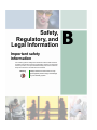
B Safety, Regulatory, and Legal Information . . . . . . . . . . . . . . . . . . . . . . .83
ii
Overview
1
Read this chapter to learn about the features and
components of your NAS (Network Attached Storage).
1
Chapter 1: Overview
Features
The Gateway 860 NAS is a 1U, high-density, powerful, rack-mountable system
that offers a new standard for flexible management and monitoring of servers
by network administrators. Features include:
■
FC-PGA (Flip-Chip Pin Grid Array) 478 processor socket that supports
Intel® Pentium® 4 processor up to 3.06 GHz with 533 MHz FSB
■
Server Works GC-SL chipset consisting of the following:
CMIC-SL (north bridge)
■
CIOBX2 (I/O bridge)
■
CSB5 (south bridge)
■
Two gigabit Ethernet controllers
■
Four DDR 200/266 DIMM slots that accept a maximum memory capacity
of 4 GB
■
One 64-bit/33 MHz PCI slot
■
Storage support for:
■
2
■
■
One slim type CD drive
■
Four hot-swap Serial-ATA hard drive bays
■
Four hard drives with RAID configurations
Front control panel
■
LCD screen and control keypad
■
2 USB ports
■
Power button
■
Serial port (for IPMI only)
■
Security lock
www.gateway.com
Features
■
Rear panel connectors
■
PS/2 keyboard port
■
PS/2 mouse port
■
Serial port (for IPMI only)
■
SCSI port
■
VGA port
■
2 LAN ports (RJ-45)
www.gateway.com
3
Chapter 1: Overview
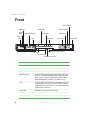
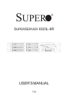
Front
Enter button
USB ports
Power
button
Previous button
Drive LEDs
RS-232 serial port
Power
LED
Next button
Alarm LED
Lock
LAN LEDs
LCD screen
CD drive manual eject hole
CD drive
CD drive LED
CD drive eject button
4
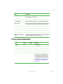
Item
Description
Power LED
Indicates the presence of power in the NAS.
Power button
Press to turn the NAS on or off.
USB ports
Connect USB peripheral devices to these ports.
BMC serial port
Connect a UPS (uninterruptable power supply) to this port.
This port is a serial management port for UPS and other
future options. This port communicates with the BMC
(Board Management Controller). For IPMI use only.
Lock
Locks the bezel. The front panel is locked when the NAS
is shipped from the factory. To unlock the bezel, insert the
supplied key into the lock and turn it counterclockwise until
it points to the unlock icon.
Drive LED
Indicates hard drive status and activity.
Alarm LED
Indicates system status.
LAN LED
Indicates LAN status and activity.
www.gateway.com
Exit button
Front
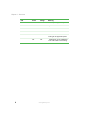
Item
Description
LCD screen
Displays the NAS name, network settings, and number of
events logged by the NAS.
Next button
Press to scroll through the menu and submenu items.
Previous button
Press to scroll through the menu and submenu items.
Enter button
Press to choose an option, to increase the numerical value
of a setting, to make a selection, or change a setting.
Exit button
Press to close a submenu or return to the menu.
CD drive
CD drive for installing software.
CD drive LED
Indicates CD drive activity.
CD drive eject button
Opens the CD drive’s disc tray.
CD drive manual eject
hole
Insert a straightened paper clip into this hole to manually
open the disc tray when the NAS is off.
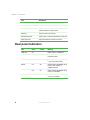
Front panel indicators
LED
Green
Power
On
The NAS is on.
Off
The NAS is off.
HDD (0, 1, 2, 3)
.
Orange
Meaning
On
Off
Hard drive status is normal.
Off
On
Hard drive activity.
Off
Off
No hard drive activity.
You can remove a hard drive from
the drive bay or hot-swap drives
when a hard drive is in this state.
For instructions on how to remove
a hard drive, see “Removing or
installing a hot-swap hard drive”
on page 37.
www.gateway.com
5
Chapter 1: Overview
LED
Green
Orange
Meaning
Alarm
On
Off
NAS is operating normally.
Off
On
System error.
Off
Off
NAS is not turned on.
On
Off
Network link is established.
On
On
Network link is established and
running at its supported speed.
Off
Off
■
LAN1 and 2
■
6
Network link is not established.
The LAN cable is not working.
www.gateway.com
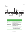
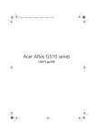
Rear
Rear
Fan
Fan
Power connector
LAN activity LED
LAN speed LED
Cover screw
PS/2 keyboard port
PS/2 mouse port
VGA
port
RS-232
serial
port
Cover screw
SCSI
connector
LAN jacks
Item
Description
Cover screws
Secure the top access cover.
Power connector
Plug the power cord into this connector.
Fan
Cools the NAS. Be careful not to block the fan's
ventilation holes. If the ventilation holes are
blocked, overheating may occur.
LAN activity indicator
Green indicates a link on the NAS’s LAN port.
When the indicator is blinking, there is LAN
activity in the NAS’s LAN port.
LAN speed LED
■
■
■
Green indicates the NAS is connected to a
Gigabit Ethernet hub.
Orange indicates the NAS is connected to a
100 Megabit Ethernet hub.
When the indicator is not lit, the NAS is
connected to a 10 Megabit Ethernet hub.
www.gateway.com
7
Chapter 1: Overview
Item
Description
PS/2 keyboard port
Plug a PS/2 keyboard into this port.
PS/2 mouse port
Plug a a PS/2 mouse into this port.
LAN jacks (LAN1, LAN2)
Plug 10 Base-T, 100 Base-TX, or 1000 Base-T
network cables into these jacks.
VGA port
Plug a monitor into this port.
RS-232 serial port
Plug a UPS or other serial device into this port.
SCSI connector
Plug a SCSI device into this connector.
Rear panel indicators
LED
Green
Orange
Meaning
LINK-ACT
On
Network link is established.
Blinking
Network link is running and
transferring data.
Off
■
■
Speed
8
Network link is not established.
The LAN cable is faulty.
On
Off
Network link is established and is
running at its maximum
supported speed.
Off
On
Network link is established and is
running at 100 Mbps.
Off
Off
Network link is established and is
running at 10 Mbps.
www.gateway.com
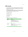
LCD screen
LCD screen
The LCD screen is a 2-line by 12-character screen that lets you see the name,
settings, date and time, event status, CPU temperature, and fan speed of the
NAS. Normally the NAS name and the IP address of the LAN 1 or 2 connection
also appears on the LCD screen.
A configuration program built into the NAS lets you configure the network
settings, view general data about the NAS, and turn off or restart the NAS. The
utility includes the following configuration information:
■
Product information
■
Network information
■
Date and time
■
Processor temperature
■
Fan speed
■
Event log
Navigate the utility by using the following keys:
Buttons
Enter
Function
Press this button to:
■
■
■
Choose an option from the menu.
Increase the numerical value of a setting.
Select and change an option’s setting.
Exit
Press this button to close a submenu or return to the
menu.
Next and
Previous
Press these buttons to:
■
■
Move the arrowhead and scroll through the menu and
submenu.
Move from one field to another.
www.gateway.com
9
Chapter 1: Overview
Storage
The NAS supplies you with the following media storage:
■
CD drive
■
High-capacity Serial-ATA hard drive
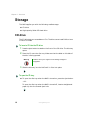
CD drive
The CD drive lets you access data on CDs. The drive cannot read DVDs or burn
CD-Rs or CD-RWs.
To insert a CD into the CD drive:
1
Press the eject button located on the front of the CD drive. The disc tray
opens.
2
Place the CD onto the disc tray. Make sure that the label or title side of
the disc is facing upward.
Warning
3
Hold the disc by the edges to avoid leaving smudges or
fingerprints.
Slide the disc tray into the NAS until it clicks into place.
To open the CD tray:
■
To open the disc tray when the NAS is turned on, press the eject button.
- OR To open the disc tray when the NAS is turned off, insert a straightened
paper clip into the manual eject hole.
10
www.gateway.com
Storage
Caring for your CDs
■
Keep your CDs in a CD case when not in use to avoid scratches or other
damage. Any kind of dirt or damage can affect the data on the disc or stop
the drive from successfully reading the disc.
■
When handling discs, always hold them by the edges to avoid smudges
or fingerprints.
■
When cleaning discs, use a clean, dust-free cloth and wipe in a straight
line from the center to the edge. Do not wipe in a circular motion.
■
Clean your CD drive periodically.
Hard drive
Your NAS came installed with four hot-swap hard drives. By default, the NAS
is configured with the RAID (redundant array of independent disks)
configurations, either RAID 0 (striped), RAID 1 (mirrored), or RAID 5 (striped
with parity).
The NAS uses a Promise PDC20275 IDE controller to support the ATA/133
channel and a high-performance ARC600-66 IDE RAID controller with four
Marvell 8818030 bridges to support the four hot-swap SATA hard drives.
When correctly configured, the NAS can provide non-stop service with a high
degree of fault tolerance through the use of RAID technology and advanced
array management features. The hard drive can be configured to RAID levels
0, 1 (0+1), 5, and 10.
www.gateway.com
11
Chapter 1: Overview
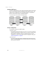
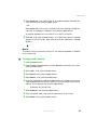
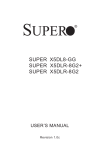
Hardware RAID layout
The NAS is recognized by the host computer’s operating system as two logical
drives. The two logical drives are configured to RAID levels 0+1 and 5. The
system volume, installed with the host operating system, is organized as
RAID 0+1 and the data volume is organized as RAID 5.
The volume layout for the NAS is illustrated below.
Raid 5
Raid 0
Raid 1
Disk 1
Raid 1
Disk 2
Disk 3
Disk 4
Volume configuration
The organized volumes on the NAS include:
■
System volume
This volume is organized as a RAID 0+1 volume. This volume includes the
operating system image. The default size for this volume is 10 GB. Use the
RAID Volume Configuration utility to configure the size. For more
information on how to use the RAID Volume Configuration utility, see
“RAID Configuration” on page 54.
■
Data volume
The remaining hard drive space is organized as the data volume using
RAID 5. For a NAS installed with four 120 GB hard drives, the data volume
size can be set to 345 GB.
12
www.gateway.com
Storage
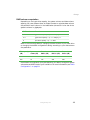
RAID volume computation
Depending on the hard drive capacity, the system volume and data volume
capacity can have different sizes. A simple formula to calculate data volume
size per RAID level is shown in the table below (where SSV is the size of the
system’s volume in gigabytes):
RAID level
Formula
5
[{(Per drive capacity × 4) – 2 × SSV}/4] × 3
0+1
[{(Per drive capacity × 4) – 2 × SSV}/4] × 2
0
(Per drive capacity × 4) – 2 × SSV
Refer to the following table for changing the data volume of your hard drive
or changing the default configuration setting according to your data volume
size preference:
Drive capacity
(GB)
System
volume (GB)
Data volume
RAID 5 (GB)
Data volume
RAID 10 (GB)
Data volume
RAID 0 (GB)
120
10
345
230
460
250
10
735
490
960
Use the RAID configuration utility bundled with your NAS to change the system
volume size and RAID level of your hard drive. For more information, see “RAID
Configuration” on page 54.
www.gateway.com
13
Chapter 1: Overview
14
www.gateway.com
Setting Up
2
This chapter provides the instructions on how to set up
your NAS and connect basic and optional peripherals.
15
Chapter 2: Setting Up
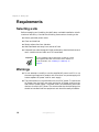
Requirements
Selecting a site
Before unpacking and installing the NAS, select a suitable installation site for
maximum efficiency. Consider the following factors when choosing a site:
■
Near a grounded power outlet
■
Clean and dust-free
■
Sturdy surface free from vibration
■
Well-ventilated and away from sources of heat
■
Protected from electromagnetic fields produced by electrical devices such
as air conditioners and radio and TV transmitters.
Important
If your installation calls for placement on table top, install
the supplied rubber feet on the bottom of the chassis. For
more information, see “Installing on a table top” on
page 19.
Warnings
16
■
Do not attempt to modify or use the supplied AC power cord if it is not
the exact type required. A product with more than one power supply will
have a separate AC power cord for each supply.
■
The power button on the NAS does not turn off AC power. To remove the
AC power from the NAS, you must unplug the AC power cord from the
wall outlet or power supply. The power cord is considered the disconnect
device to the main (AC) power. The socket outlet that the NAS plugs into
should be installed near the equipment and should be easily accessible.
www.gateway.com
Requirements
Cabinet installation technical details
Take note of the following information when planning where and how to install
the NAS:
Ambient temperature
The maximum operating temperature of the NAS is 95°F (35°C) and the
relative humidity of the NAS is in the range 20% to 80% (non-condensing).
Careful consideration should be given to installing the NAS in an
environment compatible with 95°F (35°C) maximum ambient
temperature.
Height and weight
Before installing the NAS, make sure that the surface on which you are
setting it is strong enough to bear its weight and accommodate its size.
Dimensions (including front bezel): 17.3 × 1.7 × 24.1 inches
(440 × 43.4 × 612 mm)
Weight (approximately, depending on configuration): 42 lbs. (19 kg)
Rack mounting
When mounting your NAS into a cabinet (equipment rack), make sure you
maintain correct mechanical load leveling to avoid hazardous conditions.
Power source
The NAS should be operated using only the type of power source indicated on
the product label.
■
Voltage: 100-240 V
■
Current: 6 A
■
Frequency: 50/60 Hz
www.gateway.com
17
Chapter 2: Setting Up
Circuit overloading
Appropriate consideration should be given when connecting the supply circuit
to the NAS to avoid any circuit overload. The system nameplate rating should
be used when addressing concerns about circuit overload.
Warning
Make sure that the site has the necessary capacity to
handle the NAS. Overloading electrical supply circuits is
extremely hazardous.
Reliable grounding
To avoid the potential for an electrical shock hazard, the rack assembly itself
must be suitably grounded, according to your local regional electrical codes.
This typically will require the rack to have its own separate ground. We
recommend you consult your local approved electrician.
Electrical shock
Do not operate the NAS unit without the top cover in place. Opening or
removing the cover may expose you to dangerous voltage and can cause
electrical shock.
Battery precautions
There may be a danger of explosion if the CMOS battery is incorrectly replaced.
Replace this battery with model CR2032 only. Use of another battery may
present a risk of fire or explosion. Dispose of used batteries according to
manufacturer's instructions.
Sufficient ventilation
The vents on the front panel and the fan openings on the rear panel provide
ventilation for the NAS. Make sure that these openings are not blocked and
that adequate ventilation is provided where the unit is installed.
18
www.gateway.com
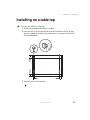
Installing on a table top
Installing on a table top
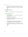
To install the NAS on a table top:
1
2
Attach the provided rubber feet to the NAS.
3
Place the NAS on the table top.
Place the NAS in an upright position so that the bottom is facing up, then
apply the adhesive surfaces of the rubber feet on the bottom of the NAS
as illustrated below.
www.gateway.com
19
Chapter 2: Setting Up
Installing into a server cabinet
Cabinet installation precautions
Before installing the NAS, take the following precautions:
20
■
The NAS is heavy. To minimize the chances of injuries, make sure that two
or more people help in installing the NAS.
■
Do not place heavy objects on the NAS.
■
Before installing, mark its intended position in the rack with a felt-tip pen.
Mounting the NAS so it is not level could result in malfunctions.
■
If you attach the two mounting ears in the forward position on each side
of the NAS, make sure that you use a four-point mounting configuration.
Do not use a two-point mounting configuration.
www.gateway.com
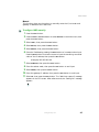
Installing into a server cabinet
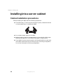
To install the NAS into a server cabinet:
1
Use a screwdriver to remove the four screws that hold the plastic covers
to the sides of the NAS.
2
Use six of the supplied flat-head screws to attach the mounting ears on
both sides of the NAS.
www.gateway.com
21
Chapter 2: Setting Up
22
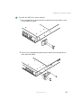
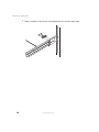
3
Temporarily fasten the rails to the sides of the NAS using the supplied
round-head screws. Position the rails based on the rack depth.
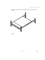
4
Using the hexagonal head screws, fasten the brackets to the back of the
rack frame.
www.gateway.com
Installing into a server cabinet
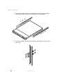
5
Two or more people must assist in lifting the NAS. Slide the back of the
rails into the brackets.
6
Using the hexagonal screws, secure the mounting ears to the front of the
rack frame.
www.gateway.com
23
Chapter 2: Setting Up
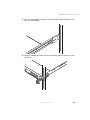
7
24
Fasten the back of the rails to the brackets with the round-head screws.
www.gateway.com
Installing into a server cabinet
8
Secure the rails on both sides of the NAS by tightening the round-head
screws.
www.gateway.com
25
Chapter 2: Setting Up
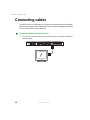
Connecting cables
The NAS, a monitor, a keyboard, and a mouse constitute the basic NAS system.
Before connecting any other peripherals, first connect the keyboard and mouse
to test if the NAS is running correctly.
To connect the basic peripheral devices:
1
26
Connect the monitor cable into the monitor/VGA connector located on
the rear panel.
www.gateway.com
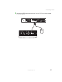
Connecting cables
2
Connect the PS/2 keyboard and mouse into the PS/2 connectors located
on the rear panel.
www.gateway.com
27
Chapter 2: Setting Up
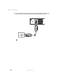
3
28
Connect the power cord to the power connector located on the rear panel,
then connect the other end to a correctly grounded power outlet.
www.gateway.com
Turning on your NAS
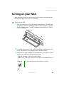
Turning on your NAS
After making sure that you have set up the NAS correctly and connected all
the required cables, you can turn on your NAS.
To turn on your NAS:
1
Open the control bay cover then press the power button. The NAS starts
and displays a welcome message. After that, a series of power-on self test
(POST) messages appear. The POST messages indicate whether the NAS is
running correctly.
2
If the NAS does not turn on or boot after pressing the power button, go
to the next section for the possible cause of the boot failure.
3
Aside from the POST messages, you can determine if the NAS is in good
condition by checking if the following occurred:
■
Power indicator on the front panel is green.
■
Num Lock, Caps Lock, and Scroll Lock LEDs on the keyboard are on.
Important
Your default Storage Server 2003 password is “gateway”.
www.gateway.com
29
Chapter 2: Setting Up
Troubleshooting
If the NAS does not boot after you turn it on, check the following factors that
might have caused the boot failure:
30
■
The external power cable may be loosely connected. Check the power cable
connection from the power source to the power cable connector on the
rear panel. Make sure that the cable is correctly connected to the power
source and to the power cable connector.
■
No power comes from the grounded power outlet. Have an electrician
check your power outlet.
■
Loose or incorrectly connected internal power cables. Ask a qualified
technician to assist you.
■
For more troubleshooting steps, see “Troubleshooting” on page 71.
www.gateway.com
Turning off your NAS
Turning off your NAS
■
Do not use the power button to shut down the NAS.
■
When the NAS shuts down, all services running on the NAS are forcibly
terminated. Before shutting down the NAS, make sure no users are
currently accessing the NAS. If you shut down the NAS while a file is being
edited, the contents of the file may be damaged.
To turn off your NAS from Microsoft® Windows®:
1
On the Windows taskbar, click Start, Shut Down, then click OK. You can
then turn off all peripherals connected to your system.
- OR If your NAS cannot receive input from the keyboard or mouse, press and
hold the power button for at least four seconds. However, keep in mind
that shutting down the NAS in this manner may damage the file system.
If this happens, the file system will attempt to repair itself the next time
the NAS starts (the larger the file system on the NAS, the longer time
required for system repair.) If the file system cannot repair itself, some or
all of the data may be lost.
To turn off your NAS from the front panel:
1
2
3
Press the Enter button.
Press the Next or Previous button to select ShutDown on the main menu,
then press the Enter button.
Select Shutdown, then press the Enter button. The “Wait for host respond”
message appears. After a few seconds, the “Shutdown OK” message appears
and the NAS shuts down.
www.gateway.com
31
Chapter 2: Setting Up
32
www.gateway.com
Customizing
Your NAS
3
Read this chapter to learn how to add options and install
or remove the hot-swap hard drives.
33
Chapter 3: Customizing Your NAS
Precautions
Before you install any computer component, we recommend that you read the
following sections. These sections contain important ESD precautions along
with pre-installation and post-installation instructions.
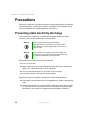
Preventing static electricity discharge
The components inside your computer are extremely sensitive to static
electricity, also known as electrostatic discharge (ESD).
Warning
ESD can permanently damage electrostatic
discharge-sensitive components in your NAS. Prevent
ESD damage by following ESD guidelines every time you
open the case.
Warning
To avoid exposure to dangerous electrical voltages and
moving parts, turn off your NAS and unplug the power cord
and network cables before opening the case.
Before opening the case, follow these guidelines:
■
Turn off your NAS.
■
Wear a grounding wrist strap (available at most electronics stores) and
attach it to a bare metal part of your computer.
■
Touch a bare metal surface on the back of the computer.
■
Unplug the power cord and the network cables.
Before working with computer components, follow these guidelines:
34
■
Avoid static-causing surfaces such as carpeted floors, plastic, and packing
foam.
■
Remove components from their antistatic bags only when you are ready
to use them. Do not lay components on the outside of antistatic bags
because only the inside of the bags provide electrostatic protection.
www.gateway.com
Expanding connectivity
Expanding connectivity
Ports let you connect peripheral devices to your NAS. For instructions on how
to connect different external devices to the NAS, see your peripheral device
user’s guide for instructions.
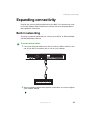
Built-in networking
The built-in network feature lets you connect your NAS to an Ethernet-based
(10/100/1000 Mbps) network.
To connect network cables:
1
Connect an Ethernet cable from a LAN connector (LAN0 or LAN1) on the
rear of the NAS to a network jack or hub on your network.
2
See your operating system user’s guide for information on how to configure
your network settings.
www.gateway.com
35
Chapter 3: Customizing Your NAS
USB
The USB (Universal Serial Bus) port is a high-speed serial bus which lets you
connect and daisy-chain USB peripherals without using system resources. Your
NAS has two USB ports available on the front panel.
36
www.gateway.com
Upgrading
Upgrading
Your NAS delivers superior power and performance. However, some users and
the applications they use may demand more. This NAS lets you upgrade key
components when you need increased performance or more storage space. The
NAS supports Serial ATA hard drives.
Important
Because all hard drives have different cooling power and
vibration characteristics, specific hard drive types have
been validated to be compatible with the NAS. For more
information, contact Gateway Technical Support.
You do not need to turn off the NAS or remove it from the cabinet when
installing or removing a hot-swap hard drive.
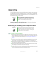
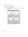
Removing or installing a hot-swap hard drive
Important
You do not need to turn off the NAS or remove it from the
cabinet (rack) to install or remove the hard drive. However,
you need to make sure that no program is accessing the
hard drive when you remove the drive.
To remove or install a hard drive:
1
Identify the defective hard drive by reading the drive LEDs on the front
panel. A defective drive LED does not light up. For information about the
location of the drive status indicators, see “Front panel indicators” on
page 5.
2
Unlock the control bay cover by inserting the supplied key into the lock
and turning it counterclockwise until it points to the unlocked icon.
3
Remove the front bezel by pressing the release latch on both sides of the
front bezel, then pulling out the bezel.
4
Remove the defective hard drive by raising the hard drive carrier handle,
then sliding the hard drive carrier out of the bay.
5
Install a new drive into the hard drive carrier. Make sure that the new hard
drive is the same drive size as the failed hard drive.
www.gateway.com
37
Chapter 3: Customizing Your NAS
6
7
38
Insert the hard drive carrier into the bay and lock it into place.
Replace the front bezel, then lock the control bay cover. The new hard
drive’s status LED lights up. The RAID recovery begins.
www.gateway.com
Configuring the
NAS
4
This chapter describes how to configure the NAS, perform
NAS functions, and view events on the NAS’s LCD screen.
39
Chapter 4: Configuring the NAS
Overview
The LCD screen lets you see at a glance the name, firmware version, and total
number of events logged by the NAS. Normally, the Windows monitoring agent
and the drivers send the messages that appear on the LCD screen.
You can instantly configure the NAS and view error events on the LCD screen
without needing to run the Administrative Tool program in Microsoft
Windows. The drivers and monitor agent on the NAS can send system error
event logs and RAID information to the LCD screen. You can set or check
network settings, date and time settings, fan speeds, and CPU temperatures,
and shut down or reboot the NAS using the LCD control panel.
After turning on the NAS, the NAS starts up and the message “OS Booting” is
displayed on the LCD screen. When the startup is complete, the NAS name and
IP address appear on the LCD screen.
40
www.gateway.com
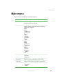
Main menu
Main menu
The LCD menu contains the following options:
Setting
Description
View Info
Displays information about the firmware and number of
events that occurred in the NAS.
Network
Lets you view and manually or automatically set the
NAS’s IP address. This menu include the following
options and commands:
LAN 1
DHCP DHCP1 On DHCP1 Off ■ OK
Manual ■
■
■
■
■
■
IPAddr1 NetMask1 GWIP1 OK
LAN 2
DHCP DHCP2 On DHCP2 Off ■ OK
Manual ■
■
■
■
■
■
Date/Time
IPAddr2 NetMask2 GWIP2 OK
Lets you perform the following:
■
■
Set Date
View Date
SystemInfo
Displays processor temperature and fan speed.
View Event
Displays events logged by the NAS or applications.
ShutDown
Lets you perform the following:
■
■
Shut down
Reboot
www.gateway.com
41
Chapter 4: Configuring the NAS
You can press any button on the front panel of the NAS to enter the main menu.
To move through the options, press the Previous or Next button until the option
you want is highlighted. To select a highlighted menu option, press the Enter
button.
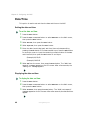
View Info
This option lets you view the name, firmware version number, and the total
number of system events listed in the event log.
(Example) WNASE 4013622 1.2.2
Events=# 7
Network
The Network option lets you view or set the NAS’s IP address.
Important
When manually entering an IP address, make sure that the
value you enter is not same with one that is currently used
by another machine in the same network. If you use an IP
address that is already used elsewhere, the message “No
error” displays on the LCD screen, indicating a
malfunction.
Some values cannot be set due to subnet mask allocation restrictions.
Configuring the LAN1 setting
DHCP (Dynamic Host Configuration Protocol)
This option lets the NAS automatically obtain IP settings from the LAN1 host.
To configure LAN1 using DHCP:
42
1
2
Press the Enter button.
3
4
Select LAN 1, then press the Enter button.
Press the Next or Previous button to select Network on the Main menu, then
press the Enter button.
Select DHCP, then press the Enter button.
www.gateway.com
Main menu
5
Select DHCP1 On if you want to get an IP address assigned automatically
from the NAS, then press the Enter button.
- OR Select DHCP1 Off if you want to manually set the IP settings (IP address,
net mask, and gateway IP address), then press the Enter button.
An asterisk appears next to the DHCP On or DHCP Off option.
6
Select OK, then press the Enter button. The “Wait host respond” message
appears on the LCD screen. After a few seconds, the “Setting OK” message
appears.
Manual
This option lets you manually enter the IP, net mask and gateway IP address
for the LAN1 host.
To configure LAN1 manually:
1
2
Press the Enter button.
3
4
5
6
Select LAN 1, then press the Enter button.
Press the Next or Previous button to select Network on the Main menu, then
press the Enter button.
Select Manual, then press the Enter button.
Select IPAddr1, then press the Enter button.
Enter the IP address by pressing the Enter button to increase number input.
Press the Next button to move the cursor to input the remaining numerical
value of the IP address, then press the Exit button.
(Example) 192.163.001.010
7
8
9
Select NetMask1, then press the Enter button.
Enter the subnet mask, then press the Exit button to end input.
Select GWIP1, then press the Enter button.
www.gateway.com
43
Chapter 4: Configuring the NAS
10
11
Enter the gateway IP address, then press the Exit button to end input.
Select OK, then press the Enter button. The “Wait host respond” message
appears on the LCD screen. After a few seconds, the “Setting OK” message
appears.
Configuring the LAN2 setting
DHCP
This option lets the NAS automatically obtain IP settings from the LAN2 host.
To configure LAN2 using DHCP:
1
2
Press the Enter button.
3
4
5
Select LAN 2, then press the Enter button.
Press the Next or Previous button to select Network on the Main menu, then
press the Enter button.
Select DHCP, then press the Enter button.
Select DHCP2 On if you want to get IP address assigned automatically from
the NAS, then press the Enter button.
- OR Select DHCP2 Off if you want to manually set the IP settings (IP address,
net mask, and gateway IP address), then press the Enter button.
An asterisk appears next to the DHCP On or DHCP Off option.
6
44
Select OK, then press the Enter button. The “Wait host respond” message
appears on the LCD screen. After a few seconds, the “Setting OK” message
appears.
www.gateway.com
Main menu
Manual
This function gives you the option to manually enter the IP, net mask and
gateway IP address of the LAN2 host.
To configure LAN2 manually:
1
2
Press the Enter button.
3
4
5
6
Select LAN 2, then press the Enter button.
Press the Next or Previous button to select Network on the Main menu, then
press the Enter button.
Select Manual, then press the Enter button.
Select IPAddr2, then press the Enter button.
Enter the IP address by pressing the Enter button to increase number input.
Press the Next button to move the cursor to input the remaining numerical
value of the IP address, then press the Exit button.
(Example) 192.163.001.010
7
8
9
10
11
Select NetMask2, then press the Enter button.
Enter the subnet mask, then press the Exit button to end input.
Select GWIP2, then press the Enter button.
Enter the gateway IP address, then press the Exit button to end input.
Select OK, then press the Enter button. The “Wait host respond” message
appears on the LCD screen. After a few seconds, the “Setting OK” message
appears.
www.gateway.com
45
Chapter 4: Configuring the NAS
Date/Time
This option is used to set and view the date and time on the NAS.
Setting the date and time
To set the date and time:
1
2
Press the Enter button.
3
4
5
Select Set Date, then press the Enter button.
Press the Next or Previous button to select Date/Time on the Main menu,
then press the Enter button.
Select Input date, then press the Enter button.
Enter the date (month/day/year) and time (hour:minute:second) by
pressing the Enter button to increase number input. Press the Next button
to move the cursor to input the remaining numerical value of the date
and time field, then press the Exit button to end input.
(Example) 01/15/02
(Example) 10:05:03
6
Select OK from the menu, then press the Enter button. The “Wait host
respond” message appears on the LCD screen. After a few seconds, the
“Setting OK” message appears.
Displaying the date and time
To display the date and time:
46
1
2
Press the Enter button.
3
Select View Date, then press the Enter button. The “Wait host respond”
message appears on the LCD screen. After a few seconds, the date and time
appear.
Press the Next or Previous button to select Date/Time on the Main menu,
then press the Enter button.
www.gateway.com
Main menu
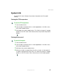
System Info
The SystemInfo menu displays the processor temperature and fan speed
reading.
Viewing the CPU temperature
To view the CPU temperature:
1
2
3
Press the Enter button.
Press the Next or Previous button to select SystemInfo on the Main menu,
then press the Enter button.
Select CPU, then press the Enter button. The “Wait host respond” message
appears on the LCD screen. After a few seconds, the processor temperature
appears.
Viewing the fan speed
To view the fan speed:
1
2
3
4
Press the Enter button.
Press the Next or Previous button to select SystemInfo on the Main menu,
then press the Enter button.
Select Fan, then press the Enter button.
Select the number corresponding to the fan you want to view speed of.
The NAS is equipped with seven fans. The “Wait host respond” message
appears on the LCD screen. After a few seconds, the fan speed appears.
www.gateway.com
47
Chapter 4: Configuring the NAS
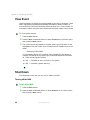
View Event
Use this submenu to display the events logged by the NAS or programs. These
event logs display hardware and software information about the NAS, as
monitored by the Microsoft Windows Administrative Tool - Event Viewer. For
information about using the Event Viewer, see the Event Viewer’s online help.
To view system events:
1
2
Press the Enter button.
3
The current event log’s sequence number, event type, and event ID are
displayed on the LCD screen. Up to 63 events can be viewed from the LCD
screen.
Press the Next or Previous button to select View Event on the Main menu,
then press the Enter button.
(Example) 1,001,A2345
In the example above, the numerical value 1 stands for the sequence
number, 001 stands for the event type, and A2345 stands for the event
ID. There are two types of events:
■
001 — Indicates an error occurred in the system
■
002 — Indicates a system warning
Shut Down
The ShutDown menu lets you turn off or restart the NAS.
Turning off the NAS
To turn off the NAS:
1
2
48
Press the Enter button.
Press the Next or Previous button to select ShutDown on the Main menu,
then press the Enter button.
www.gateway.com
Main menu
3
Select Shutdown, then press the Enter button. The “Wait for host respond”
message appears. After a few seconds the “Shutdown OK” message appears
and the NAS shuts down.
Rebooting the NAS
To reboot the NAS:
1
2
3
Press the Enter button.
Press the Next or Previous button to select ShutDown on the Main menu,
then press the Enter button.
Select Reboot, then press the Enter button. The “Wait for host respond”
message appears. After a few seconds the “Reboot OK” message appears and
the NAS restarts.
www.gateway.com
49
Chapter 4: Configuring the NAS
50
www.gateway.com
System
Management
5
This chapter gives information about the software
programs and utilities bundled with your NAS. Your NAS
supports the following system management utilities:
■
Windows Installer. This component of any Microsoft
Windows operating system lets you install drivers for
network, hard drive, and other component functions.
For more information, see “Windows installer” on
page 52.
■
RAID Configuration. This program lets you change the
RAID configuration. For more information, see “RAID
Configuration” on page 54.
■
System Image Restoration. Recovers your NAS’s
original factory default settings. For more information,
see “System Image Restoration” on page 56.
■
NAS Explorer. This program lets you locate, view
events, and manage the NAS from a remote computer.
For more information, see “NAS Explorer” on page 57.
51
Chapter 5: System Management
Windows installer
Your NAS's Windows operating system includes drivers and service support for
network, hard drive, and LCD functions. For installation procedures, refer to
the related README documents in the individual directories.
Important
The NAS is preinstalled with all the drivers and services
necessary for the NAS to function correctly. This section
is provided for software updates. If an upgrade or patched
driver is available, you can refer to the information below
to update the driver.
The Windows installer include the following components and drivers:
■
■
■
LCD software components
■
fpb.sys — LCD Windows driver.
■
WNAS_SMBus — Driver shared by fpb.sys and WNASHealthy.sys.
■
FPBSrv.exe — Windows service, needed to process LCD requests.
■
EventLog.mof — Indicates which event will be captured and sent to
the LCD screen.
■
EvConsumerSrv.exe — Service is invoked by the WMI service and
sends new events to the LCD screen.
■
InstallFPB/RemoveFPB — Installation programs that can be used to
install or remove the fpb.sys driver and FPBSrv.exe service.
Hardware healthy components
■
WNASHealthy.sys — Detects and adjusts fan speed based on processor
temperature.
■
EvConsumerSrv2.exe — A Windows service that raises the hardware
monitor events to SAK.
NAS Explorer Agent
■
■
52
NASExploreAgent.exe — A Windows service that communicates with
NAS Explorer.
Intel Network driver
www.gateway.com
Windows installer
Includes drivers and utilities to provide advanced NIC management
functions such as fail over or aggregation. For more information, see the
Intel Network driver’s online Help.
■
Disk driver
Provides performance improvement for the drive IO(s). You can update the
driver using the Device Manager utility. In the SCSI and RAID controllers
device type option, select a device such as (PDC20275-66) UDMA133 PCI ATA
2 Channel IDE Host Adapter to update your driver. For details on how to
update a driver, see the Device Manager utility’s online Help.
www.gateway.com
53
Chapter 5: System Management
RAID Configuration
This utility lets you change the default RAID configuration, such as the system
volume size and the RAID level of your hard drive.
Caution
Using the RAID Configuration utility erases all data
previously saved in the hard drives. Make sure that you
back up important files before starting the configuration
process.
Important
If you change the system volume size, you should restart
the NAS.
If you set the data volume to RAID 5, the initialization
process is performed in the background and takes several
hours to complete. During this process, you can shut down
and restart the NAS, and access the data volume.
To change the RAID configuration:
1
Insert the 860 SATA NAS Restoration CD into the CD drive. The Setup menu
appears.
2
Select RAID Configuration. The original system volume size is displayed. The
program prompts you to change the configuration of the system volume.
3
4
Select Y.
Enter a number to specify how many gigabytes will be allocated to the
system volume, then press ENTER. If the number you entered is 0, the
program prompts you to enter the new capacity again.
The program asks you to confirm the change.
5
Press Y and press ENTER to make the change, or press N and press ENTER
to abort.
The original data volume RAID level is displayed. The program prompts
you to change the configuration of the data volume.
6
54
Press Y and press ENTER to change the configuration, or press N and press
ENTER to abort. The program prompts you with the available RAID levels
to set for the data volume.
www.gateway.com
RAID Configuration
7
Select 0, 1, or 5, then press ENTER. The program prompts you to confirm
your choice of the new RAID level.
8
Press Y and press ENTER to confirm the level, or press N and press ENTER
to abort.
The program displays the message “The RAID configuration is changed,
all data will be lost after you confirm the change. Are you sure?”
9
Press Y and press ENTER to apply the changes (all data will be lost), or press
N and press ENTER to abort the changes.
The program generates the new volumes if you accepted the changes, or
aborts the changes and returns you to the main menu.
Important
If the settings have not changed, the program displays the
message “The RAID configuration is not changed.”
www.gateway.com
55
Chapter 5: System Management
System Image Restoration
This utility lets you restore the system image factory default settings.
Caution
Using the System Image Restoration utility removes all
data on the system volume. Make sure that you back up
important files before starting the restoration process.
To restore the system image:
56
1
Insert the 860 SATA NAS Restoration CD disc 1 into the CD drive and boot
to the CD. The Main Menu opens.
2
Select Restore Factory Installation to restore the system volume. A warning
message appears indicating that all data will be destroyed if you proceed
with this operation.
3
Press Y to proceed, but if you want to cancel the operation, press CTRL+C.
A message may appear asking whether the partition sizes are accurate.
4
5
6
Select Yes. The message “Proceed with disk restore?” appears.
Select Yes. The program prompts you to begin the next part of the image.
Insert the 860 SATA NAS Restoration CD disc 2 into the CD drive, then select
OK. The message “Imaging Completed Successfully” appears, and the server
restarts.
Caution
Using the System Image Restoration utility removes all
data on the system volume. Make sure that you back up
important files before starting the restoration process.
Important
Restoring the system volume should take from 15 to 30
minutes to complete, depending on your configuration.
After restoration, the data volume will not be initialized.
www.gateway.com
NAS Explorer
NAS Explorer
NAS Explorer allows NAS server management via the Web, standard network,
or dial-up connections. This utility lets you view the basic NAS configuration,
retrieve events, and configure the NAS from a remote computer.
Installing NAS Explorer
Before you begin installation, make sure that your computer has the following:
■
Intel Pentium microprocessor
■
Microsoft Windows NT, Windows 2000, Windows XP, or Windows Server
2003 operating system
■
Ethernet card
To install NAS Explorer on a Microsoft Windows platform:
1
Insert the 860 SATA NAS Application and Documentation CD into your
computer’s CD drive. The installation menu is displayed.
2
Follow the on-screen instructions to complete installation.
Uninstalling NAS Explorer
To uninstall NAS Explorer from a Microsoft Windows platform:
1
In Control Panel, double-click the Add/Remove Programs icon. The
Add/Remove Programs dialog box appears.
2
Click the listing for NAS Explorer, then click Remove. The Confirm File
Deletion dialog box appears.
3
4
Click OK to remove all components.
Click Finish to exit.
www.gateway.com
57
Chapter 5: System Management
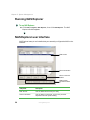
Running NAS Explorer
To run NAS Explorer:
■
Click Start, Programs, NAS Explorer, then click NAS Explorer. The NAS
Explorer window appears.
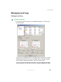
NAS Explorer user interface
NAS Explorer’s easy-to-use interface lets you remotely configure the NAS on the
network.
NAS servers
Server information
Server command
buttons
NAS Explorer
command buttons
58
Component
Description
NAS Servers
Lists the NASs discovered by the utility.
Server information
Lists the NAS’s components, such as the processor
temperature and fan speed reading.
www.gateway.com
NAS Explorer
Component
Description
Server command
buttons
These commands apply to the NAS:
■
■
■
■
NAS Explorer command
buttons
Network — Retrieves a NAS’s IP address and DNS
settings automatically from the NAS’s DHCP, or you can
manually set the NAS’s IP address, Subnet mask,
Gateway IP address, and DNS server address to
connect to the network.
Settings — Lets you remotely configure and manage
your NAS.
Event Log — Displays events logged by the NAS.
Reboot — Reboots the NAS.
These commands apply to the NAS Explorer:
■
■
■
■
Search — Finds a server on the network.
Remove — Deletes a NAS from the NAS Servers list.
Exit — Quits the application.
About — Displays the copyright notice and version
number of the application.
Finding a NAS on the network
To find a NAS on the network:
1
On the NAS Explorer window, click the Search button. When NAS Explorer
completes the search, the following dialog box appears:
2
Click Search to locate another NAS on the network, or click Search Settings
to configure the search range for locating NASs on the network. For more
information on configuring the search range settings, see “Configuring the
search range setting” on page 61.
www.gateway.com
59
Chapter 5: System Management
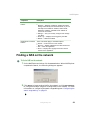
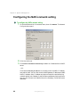
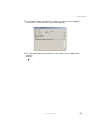
Configuring the NAS’s network setting
To configure the NAS’s network setting:
1
On the NAS Servers list, click a server name, then click Network. The Network
Config window opens.
2
3
Click the LAN host.
Click Obtain an IP address automatically to obtain an IP address from a DHCP
server.
- OR Click Use the following IP address to manually enter the NAS’s IP address
and subnet mask. You can also enter the NAS’s gateway IP address and DNS
NAS’s IP address. Both IP address and subnet mask are required during
network setting, but Gateway IP and DNS server address are optional items.
You can still connect to the NAS without the Gateway IP and DNS server
addresses.
60
www.gateway.com
NAS Explorer
4
5
Click OK. The login dialog box appears.
Enter the NAS’s user name and password, then click OK.
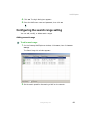
Configuring the search range setting
You can add, modify, or delete search ranges.
Adding a search range
To add a search range:
1
On the Gateway NAS Explorer window, click Search, then click Search
Settings.
The Search Range List window appears.
2
Set the search speed for discovering a NAS on the network.
www.gateway.com
61
Chapter 5: System Management
62
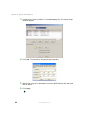
3
Double-click a client interface in the Search Range list. The Search Range
window appears.
4
Click Add. The Add Search Range dialog box appears.
5
Specify the range of IP addresses from which NAS Explorer will start and
end its search.
6
Click Apply.
www.gateway.com
NAS Explorer
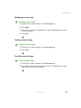
Modifying a search range
To modify a search range:
1
2
3
Double-click a client interface in the Search Range list.
4
Click Apply.
Click Modify.
Enter the new range of IP addresses from which NAS Explorer will start
and end its search.
Deleting a search range
To delete a search range:
1
2
Double-click a client interface in the Search Range list.
Click Delete.
Resetting a search range
To reset a search range:
1
2
Double-click a client interface in the Search Range list.
Click Reset to restore to default search criteria. The default search range
spans the entire network for a NAS.
www.gateway.com
63
Chapter 5: System Management
Archiving a search range
To archive a search range:
1
2
In the Search Range List window, select the search range you want to save.
Click Save As.
- OR Click the Automatically save this range set check box to save the default.sr.
file to your hard drive.
3
Click the Reload automatically on startup check box to load the file during
system startup.
4
5
In the File name box, type a name for the archived log file.
Click Save.
Opening an archived search range
To open an archived search range:
64
1
2
In the Search Range List window, click Open.
3
4
Click Open.
Click the file you want to open, then select the folder that contains the
document.
Click OK.
www.gateway.com
NAS Explorer
Managing event logs
Viewing an event log
To view an event log:
1
On the NAS Explorer window, click the Event Log button. The Event Log
window appears.
The Event Log is displayed with the Windows Event Viewer tool. It starts
automatically when you connect to the NAS. See to the Event Viewer’s
online help for detailed information about the Event Viewer.
The Event Log window displays information about the hardware, software,
system problems, monitor security events, and alerts logged by the NAS.
www.gateway.com
65
Chapter 5: System Management
The Logs pane shows a heirarchical view of the logs recorded by the
Windows Event Viewer.
Log type
Description
Application
Events logged by applications in the NAS.
System
Events logged by Windows system components.
Security
Security events logged by the NAS.
SAK alerts
Events logged by the Windows SAK in the NAS.
The Details pane shows the different event types and details of each event.
2
66
Event type
Description
Error
Indicates a loss of data or loss of functionality.
Warning
Indicates a possible problem may occur in the future.
Information
Indicates a successful operation of a program, driver, or
service in the NAS.
Successful
audits
Indicates a successful attempt to log on to the NAS.
In the Logs pane, select the log you want to view.
www.gateway.com
NAS Explorer
3
In the Details pane, double-click an event to view the event’s detailed
information. The Detail Event Log window appears.
4
To view details about the previous or next event, click the Up and Dn
buttons.
www.gateway.com
67
Chapter 5: System Management
Searching for specific types of events
To search for specific types of events:
1
68
On the NAS Explorer window, click the Event Log button. The Event Log
window appears.
www.gateway.com
NAS Explorer
2
3
4
5
In the System Event Log Search Settings area, select the type of search interval.
The types of search interval include:
Search interval
Description
Retrieve all
Recovers all events in the NAS.
Since last
retrieval
Recovers the last event viewed on the NAS Explorer.
Retrieval interval
Recovers a specific event that occurred in the NAS.
Enter the specific date and time of the event log.
Select an event.
Click Start.
Archiving an event log
To archive an event log:
1
2
3
4
On the NAS Explorer window, click the Event Log button.
Click Save. The Open dialog box appears.
In the File name box, type a name for the archived log file.
Click Save.
www.gateway.com
69
Chapter 5: System Management
70
www.gateway.com
Troubleshooting
6
Read this chapter for instructions on dealing with common
problems. If problems still persist, contact Gateway
Technical Support.
71
Chapter 6: Troubleshooting
Telephone support
Before calling Gateway Technical Support
If you have a technical problem with your NAS, follow these recommendations
before contacting Gateway Technical Support:
72
■
Make sure that your NAS is connected correctly to a grounded AC outlet
that is supplying power.
■
If a peripheral device, such as a keyboard or mouse, does not appear to
work, make sure that all cables are plugged in securely and plugged into
the correct port or jack.
■
If you have recently installed hardware or software, make sure that you
have installed it following the instructions provided with it. If you did not
purchase the hardware or software from Gateway, see the manufacturer’s
documentation and technical support resources.
■
If you have “how to” questions about using a program, see:
■
The program’s online Help
■
The program’s documentation
■
Your operating system’s documentation
■
The software or hardware manufacturer’s Web site
■
Have your client ID, serial number (located on the side or back of your
case), and order number available, along with a detailed description of your
issue, including the exact text of any error messages, and the steps you
have taken.
■
Make sure that your NAS is nearby at the time of your call. The technician
may have you follow appropriate troubleshooting steps.
■
Consider using Gateway’s online technical support. Gateway’s Web site has
FAQs, tips, and other technical help. You can also use the Web site to e-mail
Technical Support. For more information, visit Gateway’s Technical
Support Web site at support.gateway.com.
www.gateway.com
Telephone support
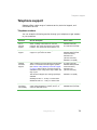
Telephone support
Gateway offers a wide range of customer service, technical support, and
information services.
Telephone numbers
You can access the following services through your telephone to get answers
to your questions:
Resource
Service description
How to reach
Fax on
demand
support
Order a catalog of documents on common
problems, then order documents by document
numbers. The documents will be faxed to you.
800-846-4526 (US)
877-709-2951 (Canada)
Tutorial
support
Learn networking tips from Gateway’s tutorial
support on a per-issue fee basis.
877-485-1464 (US)
800-846-3609 (Canada
and Puerto Rico)
605-232-2191
(all other countries)
800-846-1778 (TDD)
Gateway
Technical
Support
Talk to a Gateway Technical Support representative
about a non-tutorial technical support question.
(See “Before calling Gateway Technical Support”
on page 72 before calling.) Technical support is
available 24 hours a day, seven days a week, 365
days a year.
877-485-1464 (US)
800-846-3609 (Canada
and Puerto Rico)
605-232-2191
(all other countries)
TDD Technical Support (for hearing impaired) is
available:
800-846-1778 (TDD)
Weekdays 6:00 a.m. - 8:00 p.m. Central Time
Weekends 6:00 a.m. - 5:00 p.m. Central Time
Sales,
accounting,
and warranty
Get information about available systems, pricing,
orders, billing statements, warranty service, or
other non-technical issues.
www.gateway.com
800-846-2000 (US)
888-888-2037 (Canada)
73
Chapter 6: Troubleshooting
Safety guidelines
While troubleshooting your NAS, follow these safety guidelines:
■
Never remove the top cover while your NAS is turned on and while the
network cable and the power cords are connected.
■
Make sure that you are grounded correctly before opening the NAS. For
more information about preventing damage from static electricity, see
“Preventing static electricity discharge” on page 34.
■
After you complete any maintenance task where you have to remove the
top cover, make sure that you close the case and reconnect all cables before
you restart your NAS.
Warning
To avoid bodily injury, do not attempt to troubleshoot your
NAS problem if:
■
■
■
■
The power cords or plugs are damaged
Liquid has been spilled into your NAS
Your NAS was dropped
The case was damaged
Instead, unplug your NAS and contact a qualified computer
technician. If your NAS was damaged during shipment
from Gateway, contact Gateway Technical Support. For
more information, see “Telephone support” on page 72.
74
www.gateway.com
Troubleshooting steps
Troubleshooting steps
The NAS does not work.
■
Make sure that the power button on the front panel is turned on.
■
Make sure that the power cable is connected correctly.
■
Turn off the NAS by pressing the power button, then restart the NAS.
During the startup procedure, the NAS checks the file system. The length
of this check varies depending on the amount of data on the NAS (in some
extreme cases, it can take as long as two hours).
The NAS cannot be accessed from a browser.
■
Make sure that the network cable is connected correctly.
■
Make sure that the LINK LED and ACT LED are lit.
■
Make sure that the IP address entered on the browser is correct.
■
Make sure that no other networked device is using the same IP address as
the NAS.
■
Make sure that the network cable is not damaged.
■
Make sure that there is no problem with the connection between the
network hub and the computer, NAS, or hub connectors.
NAS cannot read the CD information.
■
Make sure that you are using the correct type of disc.
■
Make sure the CD is correctly inserted in the drive.
■
Make sure that the CD is clean and is not scratched.
A new peripheral is not working correctly.
■
Make sure that the cables for the new peripheral are firmly connected and
that the pins are not bent.
■
See the documentation that came with the new peripheral to see if any
device drivers need to be installed.
■
Make sure that the network status indicator lights up.
■
Check the cabling and network equipment for the correct connection.
■
Reinstall the network drivers.
www.gateway.com
75
Chapter 6: Troubleshooting
A peripheral device connected to a USB connector does not work.
■
Reduce the number of external devices connected to a USB hub.
■
See the documentation that comes with the device.
Cannot eject CD drive tray
■
76
Insert the tip of a straightened paper clip into the manual eject hole of
the CD drive tray.
www.gateway.com
Glossary
A
10 Base-T
A UTP cable consisting of four pairs of two wires
(8 conductors) each, twisted together into a single
unshielded set (the cable is not enclosed in a metallic mesh
for blocking electromagnetic noise). Also referred to as a
twisted pair cable, it is commonly used for connection in
Ethernet-based local area networks.
A cable of this type is capable of carrying unmodulated
signal data at the rate of 10 megabits per second over
distances of up to 328 feet (100 meters) (with the 10 Mbps
base band system).
77
Appendix A: Glossary
100 Base-TX
A UTP cable consisting of four pairs of two wires (8 conductors) each, twisted
together into a single unshielded set (the cable is not enclosed in a metallic
mesh for blocking electromagnetic noise). This is referred to as a twisted pair
cable. These cables meet the category 5 specifications for such cables.
A cable of this type is capable of carrying unmodulated signal data at the rate
of 100 megabits per second over distances of up to 328 feet (100 meters) (with
the 100 Mbps base band system). It is used for connecting to local area networks
using fast Ethernet, which operate at speeds in excess of 10 Mbps (data transfer
at the rate of 10 megabits per second).
Capacity limit
Limits the amount of drive space that a particular user can use. Also referred
to as a quota or disk quota.
DHCP (Dynamic Host Configuration Protocol)
A protocol for easily assigning dynamic IP addresses to devices on a network.
With DHCP, IP addresses can be traced by the software without requiring an
administrator to manually manage the task.
Event Viewer
An administrative tool that is used to view and manage logs of system, program,
and security events on your NAS. The Event Viewer displays five types of events:
■
Error
An error log describes a significant problem that has occurred, such as a
loss of data or loss of functionality.
■
Warning
A warning log indicates a potential problem in the future.
■
Information
An information log describes operation of an application, driver, or service.
■
Success audit
A success audit event is a user’s successful attempt to log on to the NAS.
■
Failure audit
A failure audit log is a failure to access a network drive.
78
www.gateway.com
Hub
A switching device through which a number of devices (such as computers)
can be connected to a network. Since connected devices are arrayed with the
hub at the center, this type of connection is referred to as a star topology. Most
hubs used with the Internet are equipped with a signal amplifier (repeater) to
support physical extensions.
IP address
An identifier used to indicate the addresses of devices (such as computers) that
are connected to a network. Because this identifier is used to designate a
particular destination during data exchange, each IP address must be unique.
The address consists of four period-delimited fields, each field being a number
from 0 to 255.
LAN (Local Area Network)
A network encompassing a relatively limited area, such as a building, a floor,
an organization, or a company.
LED (Light-Emitting Diode)
A diode that emits light and is used as a status indicator.
Log
A record of events occurring during operation, along with their times of
occurrence, or the file containing such a record. For example, an error log
contains a list of errors occurring in the NAS, while an access log records access
to the NAS.
Mount
To make accessible, either by connecting to the computer itself or by placing
onto the hard drive or other storage medium of a computer on the network.
Network card
A device installed in a computer or router to enable connection to a network.
A network card is equipped with a port (connector) for connection to a
1000 base-T, 100 Base-TX, 10 Base-T, or other network cable. Also referred to
as a LAN card, LAN board, or NIC (network interface card).
Network system
A system for sharing resources such as files and printers.
www.gateway.com
79
Appendix A: Glossary
NFS (Network File System)
A method for sharing files over a network. NFS makes it possible to use files
located on another computer on the network as if they were located on your
own machine. A trademark of Sun Microsystems, it is primarily used with UNIX,
but has also been adapted for use with Microsoft Windows operating systems.
Operating system
Basic software that manages and controls operation of a computer. Microsoft®
Windows® and UNIX are operating systems.
RAID
RAID (redundant array of independent disks) is an array of multiple,
independent hard drives that provide high performance and fault tolerance.
The RAID subsystem controller implements several levels of the Berkeley RAID
technology. An appropriate RAID level is selected when the volume sets are
defined or created. This decision is based on drive capacity, data availability,
(fault tolerance or redundancy), and drive performance.
RAID level
RAID level refers to the level of data performance and protection of a volume
set. RAID arrays can be implemented in several ways, using technologies such
as mirroring, striping, duplexing, and parity. The RAID levels supported in the
RAID subsystem are RAID 0, RAID 1, RAID 10 and RAID 5.
RAID 0
RAID 0, also known as striping, is the simplest RAID level. RAID 0 does not
involve data redundancy, but it does offer the best high-speed data throughput.
RAID 0 breaks up data into smaller blocks, then writes a block to each drive in
the array.
RAID 1
RAID 1, also known as disk mirroring, writes data simultaneously to several
duplicate drives. If one drive fails, the other drive(s) continues to function as
a single drive until the failed drive is replaced.
RAID 5
RAID 5 is also known as striping with parity at byte level. In RAID 5, both data
and parity information are written to all of the drives in the subsystem. If one
drive in the system fails, the parity information can be used to reconstruct the
data from that drive. All drives in the array system can be used for a seek
operation at the same time, thereby increasing the performance of the RAID
system.
80
www.gateway.com
RAID 10
RAID 10 is a combination of RAID 0 and RAID 1, striping and disk mirroring.
RAID Level 10 combines the fast performance of Level 0 with the data
redundancy of Level 1. In this configuration, data is distributed across several
drives, similar to Level 0. Then the data are duplicated to another set of drives
for data protection. RAID 10 provides the highest read/write performance of any
of the hybrid RAID levels.
RAID 0+1
RAID 0+1 is a mirrored array whose segments are RAID 0 arrays. It has the same
fault tolerance as RAID 5, and the same overhead for fault tolerance as mirroring
alone. This RAID has excellent performance, but not maximum reliability.
Rack mount
Ordinarily, a 19-inch rack (cabinet) in which servers or drive units made to fit
such a rack are mounted. A rack mount kit is hardware, such as sliding rails,
for mounting devices in such a rack.
Router
A repeater for connecting multiple networks. A router determines the optimum
path (route) for forwarding received data, and provides control over a higher
level of processing than a device such as a hub. A router is used in constructing
medium- to large-scale networks.
Server
A computer that provides many types of services to computers attached to it.
Examples include file servers, Web servers, and data servers.
Service
A task (sometimes known as a process) or application that resides in the system
and runs in the background. Also referred to as a daemon or driver.
Subnet mask
A number that is used for dividing IP addresses used on a TCP/IP network into
network numbers and host numbers. This method is used to allow different
networks that are connected through a router to recognize that they are
different networks.
www.gateway.com
81
Appendix A: Glossary
TCP/IP protocol
Generally used to refer to the established set of means and procedures by which
devices connected to a TCP/IP network communicate with one another. TCP/IP
is the most widely used of the various protocols, and is also used on the Internet.
Volume set
Volume set is a single logical device. It is organized in a RAID level with one
or more physical drives. A volume set must be created either on an existing
RAID set or on a group of available individual drives.
Web server
A server machine that distributes data for viewing over the Web, or the service
provided by such a machine. Also referred to as a WWW (World Wide Web)
server.
Windows network
A network built from machines that use a Microsoft® operating system. Uses
a protocol called NetBEUI.
Windows Administrative tools
A collection of Windows tools (Component Services, Computer Management,
Data Sources, Event Viewer, Local Security Policy, Performance and Services) for
remotely managing a server from a computer running Windows.
82
www.gateway.com
Safety,
Regulatory, and
Legal Information
B
Important safety
information
Your Gateway system is designed and tested to meet the latest standards
for safety of information technology equipment. However, to ensure safe
use of this product, it is important that the safety instructions marked on
the product and in the documentation are followed.
Warning
Always follow these instructions to help
guard against personal injury and damage
to your Gateway system.
83
Appendix B: Safety, Regulatory, and Legal Information
Setting up your system
84
■
Read and follow all instructions marked on the product and in the documentation before you
operate your system. Retain all safety and operating instructions for future use.
■
Do not use this product near water or a heat source such as a radiator.
■
Set up the system on a stable work surface.
■
The product should be operated only from the type of power source indicated on the rating label.
■
If your computer has a voltage selector switch, make sure that the switch is in the proper position
for your area. The voltage selector switch is set at the factory to the correct voltage.
■
Openings in the computer case are provided for ventilation. Do not block or cover these
openings. Make sure you provide adequate space, at least 6 inches (15 cm), around the system for
ventilation when you set up your work area. Never insert objects of any kind into the computer
ventilation openings.
■
Some products are equipped with a three-wire power cord to make sure that the product is
properly grounded when in use. The plug on this cord will fit only into a grounding-type outlet.
This is a safety feature. If you are unable to insert the plug into an outlet, contact an electrician
to install the appropriate outlet.
■
If you use an extension cord with this system, make sure that the total ampere rating on the
products plugged into the extension cord does not exceed the extension cord ampere rating.
■
If your system is fitted with a TV Tuner, cable, or satellite receiver card, make sure that the
antenna or cable system is electrically grounded to provide some protection against voltage
surges and buildup of static charges.
www.gateway.com
Care during use
■
Do not walk on the power cord or allow anything to rest on it.
■
Do not spill anything on the system. The best way to avoid spills is to avoid eating and drinking
near your system.
■
Some products have a replaceable CMOS battery on the system board. There is a danger of
explosion if the CMOS battery is replaced incorrectly. Replace the battery with the same or
equivalent type recommended by the manufacturer. Dispose of batteries according to the
manufacturer’s instructions.
■
When the computer is turned off, a small amount of electrical current still flows through the
computer. To avoid electrical shock, always unplug all power cables and modem cables from the
wall outlets before cleaning the system.
■
Unplug the system from the wall outlet and refer servicing to qualified personnel if:
■
The power cord or plug is damaged.
■
Liquid has been spilled into the system.
■
The system does not operate properly when the operating instructions are followed.
■
The system was dropped or the cabinet is damaged.
■
The system performance changes.
Replacement parts and accessories
Use only replacement parts and accessories recommended by Gateway.
Important
Warning
Do not use Gateway products in areas classified as
hazardous locations. Such areas include patient care
areas of medical and dental facilities, oxygen-laden
environments, or industrial facilities.
To reduce the risk of fire, use only No. 26 AWG or larger
telecommunications line cord.
www.gateway.com
85
Appendix B: Safety, Regulatory, and Legal Information
Regulatory compliance
statements
United States of America
Federal Communications Commission (FCC)
Unintentional emitter per FCC Part 15
This device has been tested and found to comply with the limits for a Class A digital device,
pursuant to Part 15 of the FCC rules. These limits are designed to provide reasonable protection
against harmful interference in a residential installation. This equipment generates, uses, and can
radiate radio frequency energy and, if not installed and used in accordance with the instructions,
may cause harmful interference to radio or television reception. However, there is no guarantee
that interference will not occur in a particular installation. If this equipment does cause
interference to radio and television reception, which can be determined by turning the equipment
off and on, the user is encouraged to try to correct the interference by one or more of the following
measures:
■
Reorient or relocate the receiving antenna
■
Increase the separation between the equipment and receiver
■
Connect the equipment to an outlet on a different circuit from that to which the receiver is
connected
■
Consult the dealer or an experienced radio/TV technician for help.
Compliance Accessories:
All connections to other computing devices must be made using shielded cables to maintain
compliance with FCC regulations. Only peripherals (input/output devices, terminals, printers, etc.)
certified to comply with the Class B limits may be attached to this equipment. Operation with
noncertified peripherals is likely to result in interference to radio and TV reception.
FCC declaration of conformity
Responsible party:
Gateway Companies, Inc.
610 Gateway Drive, North Sioux City, SD 57049
(605) 232-2000 Fax: (605) 232-2023
Product:
■
Gateway 860 NAS
For unique identification of the product configuration, please submit the 10-digit serial number
found on the product to the responsible party.
This device complies with Part 15 of the FCC Rules. Operation of this product is subject to the
following two conditions: (1) this device may not cause harmful interference, and (2) this device
must accept any interference received, including interference that may cause undesired operation.
86
www.gateway.com
Caution
Changes or modifications not expressly approved by
Gateway could void the FCC compliance and negate your
authority to operate the product.
Telecommunications per Part 68 of the Code of Federal Regulations (CFR 47)
(applicable to products fitted with USA modems)
Your modem complies with Part 68 of the Code of Federal Regulations (CFR 47) rules. On the
computer or modem card is a label that contains the CFR registration number and Ringer
Equivalence Number (REN) for this device. If requested, this information must be provided to the
telephone company.
A telephone line cord with a modular plug is required for use with this device. The modem is
designed to be connected to the telephone network or premises wiring using a compatible modular
jack which is Part 68-compliant. See installation instructions for details.
The Ringer Equivalence Number (REN) is used to determine the number of devices which may be
connected to the telephone line. Excessive RENs on a telephone line may result in the devices not
ringing in response to an incoming call. In most areas, the sum of RENs should not exceed five
(5.0). To be certain of the number of devices that may be connected to a line, as determined by the
total RENs, contact the local telephone company.
If this device causes harm to the telephone network, the telephone company will notify you in
advance that temporary discontinuance of service may be required. The telephone company may
request that you disconnect the equipment until the problem is resolved.
The telephone company may make changes in its facilities, equipment, operations, or procedures
that could affect the operation of this equipment. If this happens, the telephone company will
provide advance notice in order for you to make necessary modifications to maintain
uninterrupted service.
This equipment cannot be used on telephone company-provided coin service. Connection to party
line service is subject to state tariffs. Contact the state public utility commission or public service
commission for information.
When programming or making test calls to emergency numbers:
■
Remain on the line and briefly explain to the dispatcher the reason for the call.
■
Perform such activities in the off-peak hours such as early morning or late evenings.
The United States Telephone Consumer Protection Act of 1991 makes it unlawful for any person to
use a computer or other electronic device to send any message via a telephone fax machine unless
such message clearly contains, in a margin at the top or bottom of each transmitted page or on the
first page of the transmission, the date and time it is sent, an identification of the business, other
entity, or other individual sending the message, and the telephone number of the sending
machine or such business, other entity, or individual. Refer to your fax communication software
documentation for details on how to comply with the fax-branding requirement.
www.gateway.com
87
Appendix B: Safety, Regulatory, and Legal Information
Canada
Industry Canada (IC)
Unintentional emitter per ICES-003
This digital apparatus does not exceed the Class A limits for radio noise emissions from digital
apparatus as set out in the radio interference regulations of Industry Canada.
Le présent appareil numérique n’émet pas de bruits radioélectriques dépassant les limites
applicables aux appareils numériques de Classe A prescrites dans le règlement sur le brouillage
radioélectrique édicté par Industrie Canada.
Telecommunications per Industry Canada CS-03
(for products fitted with an IC-compliant modem)
The Industry Canada label identifies certified equipment. This certification means that the
equipment meets certain telecommunications network protective, operation, and safety
requirements. The Department does not guarantee the equipment will operate to the users’
satisfaction.
Before installing this equipment, users should make sure that it is permissible to be connected to
the facilities of the local telecommunications company. The equipment must also be installed
using an acceptable method of connection. In some cases, the inside wiring associated with a
single-line individual service may be extended by means of a certified connector assembly. The
customer should be aware that compliance with the above conditions may not prevent
degradation of service in some situations.
Repairs to certified equipment should be made by an authorized Canadian maintenance facility
designated by the supplier. Any repairs or alterations made by the user to this equipment, or
equipment malfunctions, may give the telecommunications company cause to request the user to
disconnect the equipment.
Users should make sure, for their own protection, that the electrical ground connections of the
power utility, telephone lines, and internal metallic water pipe system, if present, are connected
together. This precaution may be particularly important in rural areas.
Warning
To avoid electrical shock or equipment malfunction do not
attempt to make electrical ground connections by yourself.
Contact the appropriate inspection authority or an
electrician, as appropriate.
The Ringer Equivalence Number (REN) assigned to each terminal device provides an indication of
the maximum number of terminals allowed to be connected to a telephone interface. The
termination on an interface may consist of any combination of devices subject only to the
requirement that the sum of the Ringer Equivalence Numbers of all the devices does not exceed 5.
88
www.gateway.com
Laser safety statement
All Gateway systems equipped with CD and DVD drives comply with the appropriate safety
standards, including IEC 825. The laser devices in these components are classified as “Class 1 Laser
Products” under a US Department of Health and Human Services (DHHS) Radiation Performance
Standard. Should the unit ever need servicing, contact an authorized service location.
Warning
Use of controls or adjustments or performance of
procedures other than those specified in this manual may
result in hazardous radiation exposure. To prevent
exposure to laser beams, do not try to open the enclosure
of a CD or DVD drive.
California Proposition 65 Warning
Warning
This product contains chemicals, including lead, known to
the State of California to cause cancer, birth defects, or
reproductive harm.
www.gateway.com
89
Appendix B: Safety, Regulatory, and Legal Information
Notices
Copyright © 2003 Gateway, Inc.
All Rights Reserved
14303 Gateway Place
Poway, CA 92064 USA
All Rights Reserved
This publication is protected by copyright and all rights are reserved. No part of it may be reproduced or
transmitted by any means or in any form, without prior consent in writing from Gateway.
The information in this manual has been carefully checked and is believed to be accurate. However, changes are
made periodically. These changes are incorporated in newer publication editions. Gateway may improve and/or
change products described in this publication at any time. Due to continuing system improvements, Gateway is
not responsible for inaccurate information which may appear in this manual. For the latest product updates,
consult the Gateway Web site at www.gateway.com. In no event will Gateway be liable for direct, indirect, special,
exemplary, incidental, or consequential damages resulting from any defect or omission in this manual, even if
advised of the possibility of such damages.
In the interest of continued product development, Gateway reserves the right to make improvements in this
manual and the products it describes at any time, without notices or obligation.
Trademark Acknowledgments
1-800-GATEWAY, ActiveCPR, ALR, AnyKey, black-and-white spot design, CrystalScan, Destination, DestiVu, EZ
Pad, EZ Point, Field Mouse, Gateway 2000, Gateway Country, gateway.net, Gateway stylized logo, Perfect
Scholar, Solo, TelePath, Vivitron, stylized “G” design, and “You’ve got a friend in the business” slogan are
registered trademarks and black-and-white spotted box logo, GATEWAY, Gateway Astro, Gateway@Work,
Gateway Connected touch pad, Gateway Connected music player, Gateway Cyber:)Ware, Gateway
Education:)Ware, Gateway Flex Case, Gateway Gaming:)Ware, Gateway GoBack, Gateway Gold, Gateway
Learning:)Ware, Gateway Magazine, Gateway Micro Server, Gateway Money:)Ware, Gateway Music:)Ware,
Gateway Networking Solutions, Gateway Online Network (O.N.) solution, Gateway Photo:)Ware, Gateway
Professional PCs, Gateway Profile, Gateway Solo, green stylized GATEWAY, green stylized Gateway logo,
Gateway Teacher:)Ware, Gateway Video:)Ware, HelpSpot, InforManager, Just click it!, Learn@Gateway, Kids
BackPack, SERVE-TO-ORDER, Server Watchdog, the Spotted G Gateway Logo and the Spotted G Logo,
SpotShop, Spotshop.com, and Your:)Ware are trademarks of Gateway, Inc. Intel, Intel Inside logo, and Pentium
are registered trademarks and MMX is a trademark of Intel Corporation. Microsoft, MS, MS-DOS, and Windows
are trademarks or registered trademarks of Microsoft Corporation. All other product names mentioned herein are
used for identification purposes only, and may be the trademarks or registered trademarks of their respective
companies.
90
www.gateway.com
A MAN 1U NAS USER GDE R0 12/03