1
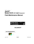
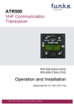
No part of this document may be reproduced in any form or
by any means without the express written consent of Garmin
AT, Inc.
II Morrow, Garmin AT, and Apollo are trademarks of
Garmin AT, Inc.
© 2003 by Garmin AT, Inc. All rights reserved.
Printed in the U.S.A.
Garmin AT, Inc.
2345 Turner Road S.E.
Salem, OR 97302
U.S.A. Toll Free
Canada Toll Free
International
FAX
800.525.6726
800.654.3415
503.391.3411
503.364.2138
Visit our web page at http://www.garminat.com
Send comments about this manual by e-mail to:
[email protected]
Welcome ...
Welcome to a new era of aviation communication. Once
again, Garmin AT, Inc. has set new standards in features
and ease of use for the general aviation public. The
Apollo SL40 is a VHF Communications Transceiver for
use by the aviation pilot. Packaged in a new slim form
factor that helps you get the most out of limited panel
real estate without limiting features and performance.
The Apollo SL40 is unequaled in providing the features,
level of performance, and reliability that aviation users
expect. The Apollo slim line series of avionics sets a
precedent that will be the standard that all other avionics
will be compared to. You can be confident in knowing
that you are the owner of the state-of-the-art in aviation
communication. Our products are built to last and to
allow for upgrading as your needs change in the future.
The SL40 is also packaged in configurations to meet the
needs of customers for base station and mobile
applications. Contact the Garmin AT factory for more
details.
i
History of Revisions
December 1996
March 1997
June 1998
September 2003
Original Release
Rev. -01
Rev. -02
Rev. -02a
Ordering Information
To receive additional copies of the Apollo SL40 User’s Guide,
order part #560-0954-02a. The Apollo SL40 Installation
Guide is part #560-0956-xx.
ii
Table of Contents
Welcome ... · · · · · · · · · · · · · · · · · · · · · · · i
History of Revisions · · · · · · · · · · · · · · · · · · ii
Ordering Information · · · · · · · · · · · · · · · · · ii
Introduction · · · · · · · · · · · · · · · · · · · · · · 1
Display· · · · · · · · · · · · · · · · · · · · · · · 1
Annunciators· · · · · · · · · · · · · · · · · · · · 1
Controls · · · · · · · · · · · · · · · · · · · · · · 2
Buttons· · · · · · · · · · · · · · · · · · · · · · · 2
Basic Operation · · · · · · · · · · · · · · · · · · · · 3
Power On/Off · · · · · · · · · · · · · · · · · · · 3
Volume · · · · · · · · · · · · · · · · · · · · · · 3
Selecting Frequencies · · · · · · · · · · · · · · · 3
Frequency Monitoring · · · · · · · · · · · · · · · 4
Recalling a Frequency · · · · · · · · · · · · · · · 4
Remote (REM) · · · · · · · · · · · · · · · · 4
Auto Stack List (LST)· · · · · · · · · · · · · 5
User Stored Frequencies (MEM) · · · · · · · 5
Weather (WTH) · · · · · · · · · · · · · · · · 6
Aborting a Frequency Recall · · · · · · · · · 6
Removing a Frequency from User Memory · 7
Replacing a Frequency from User Memory· · 7
Assigning an ID to a User Frequency · · · · · 8
iii
Intercom Function · · · · · · · · · · · · · · · · · 9
Stuck Mic · · · · · · · · · · · · · · · · · · · · · 9
System Functions · · · · · · · · · · · · · · · · · · · 10
Software Version · · · · · · · · · · · · · · · · · 10
RF Level · · · · · · · · · · · · · · · · · · · · · 11
Noise Level· · · · · · · · · · · · · · · · · · · · 11
Headphone Level · · · · · · · · · · · · · · · · · 11
Mic Squelch 1 and 2 · · · · · · · · · · · · · · · 12
Transmit Mic · · · · · · · · · · · · · · · · · · · 12
Intercom Level · · · · · · · · · · · · · · · · · · 12
Sidetone Level · · · · · · · · · · · · · · · · · · 13
Display Brightness · · · · · · · · · · · · · · · · 13
SL40 Specifications · · · · · · · · · · · · · · · · · 14
Features· · · · · · · · · · · · · · · · · · · · · · 14
Performance · · · · · · · · · · · · · · · · · · · 14
Physical· · · · · · · · · · · · · · · · · · · · · · 15
iv
Introduction
This guide describes the operation of the Apollo SL40
VHF Communication Transceiver.
Transmit
Annunciator
Active
Frequency
Standby
Symbol
COM
119.80
PULL SQUELCH
Standby
Frequency
Large, Outer
Knob
s121.50
Small, Inner
Knob
A POLLO SL40
TX
VOL
Photocell
EC
MON
RCL
MEM
OFF
Power/Volume/Squelch
Flip/Flop Emergency
Frequency
Channel
Display
Store
Memory
Frequency
Monitor
Recall
Memory
The 1-line by 16-character display is composed of 5x7
dot matrix alphanumeric high intensity LEDs. A
photocell is located in the top left corner of the front
panel display. The photocell automatically controls the
intensity of the display from low brightness at night to
high brightness during daylight operation. Brightness
levels may also be controlled manually.
Annunciators Several annunciators are used to help indicate the
operating modes of your Apollo SL40. The TX
(Transmit) annunciator is lighted whenever you are
transmitting. If the avionics bus drops below 9 VDC, the
SL40 will not transmit. An LED will be lighted above
the MON and RCL buttons when these functions are
selected. An “s” will appear to the left of the Standby
frequency. An “m” will appear to the left of the Standby
frequency when you are using the Monitor function. An
“I” indicates the Intercom function is being used.
TX - Transmit
s - Standby Frequency
m - Monitor Mode
I - Intercom
1
Controls
PULL SQUELCH
VOL
OFF
Power/Volume/Squelch
The knob on the left side of the SL40 controls power
on/off, volume, and squelch test. Rotate the knob
clockwise (CW) past the detent to turn the power on.
Continuing to rotate the knob to the right increases
speaker and headphone amplifier volume level. Rotate
the knob to the left to reduce the volume level. Pull the
knob out to disable automatic squelch. The SL40 may be
installed to have the on/off switch disabled and to have
power controlled from the avionics panel.
Large and Small Knobs
The dual concentric knobs on the right side of the SL40
are used to select frequencies or to view the features
available within a function. Details are provided in the
appropriate section.
Buttons
Five backlighted buttons allow you to access the
functions in your Apollo SL40.
Flip/Flop (Arrows)
Press the Flip/Flop button to switch between the active
(left-most) and standby (right-most) frequency.
Switching between frequencies is disabled while you are
transmitting.
EC
MON
RCL
MEM
2
EC (Emergency Channel)
Press the EC button to load the Emergency Channel
(121.500 MHz) as the standby frequency. The Monitor
function is automatically enabled.
MON (Monitor)
Press the MON button to listen to the standby frequency.
When the active frequency receives a signal, the unit
will switch automatically to the active frequency.
RCL (Recall)
Press the RCL button to retrieve stored frequencies.
MEM (Memory)
Press the MEM button to store the displayed Standby
frequency in memory.
Basic Operation
Basic Operation
This section introduces the basic operating details of the
Apollo SL40 VHF Communications Transceiver.
Power
On/Off
Turn the Power/Volume control clockwise past the OFF
detent. The SL40 may be installed to be powered from
the avionics panel so the on/off control will be disabled.
Volume
Turn the Power/Volume control clockwise to increase
the volume level and counterclockwise to decrease
volume.
Selecting
Frequencies
New frequencies are first selected as a Standby
frequency and then toggled to the Active side when
desired. While viewing the frequency display, use the
Large and Small knobs on the right side of the SL40 to
select the desired frequency.
119.80
1. Turn the Large, outer knob to change
the values in 1 MHz increments. The
MHz selection range is between 118 and
136 in 1 MHz steps.
119.80
2. Turn the Small, inner knob to change
the values in 25 kHz increments. The
kHz selection range is between 000 and
975 kHz in 25 kHz steps. Note that only
two digits are displayed to the right of
the decimal point.
Turn the Large and Small knobs clockwise to increase
and counterclockwise to decrease the frequency values.
Standby frequency selection is not inhibited during
transmit.
119.80
s121.50
121.50
s119.80
Press the Flip/Flop button to toggle the
Standby frequency to the Active
frequency.
3
Basic Operation
Frequency
Monitoring
The Frequency Monitoring function allows you to listen
to the Standby frequency, while monitoring the Active
frequency for activity.
MON
119.10 > m121.50
Recalling a
Frequency
Press the MON button to listen to the
standby frequency. A small “m” is
displayed in front of the Standby
frequency. When the Active frequency
receives a signal, the unit will switch
automatically to the Active frequency
and then switch back when activity
ceases. An arrow (< or >) will point to
the frequency that you are currently
listening to. A slight clicking sound
occurs when the radio is checking the
Active frequency for activity. The
Monitor function is deactivated when
you press MON.
The SL40 can access several areas of stored frequencies.
The SL40 can also receive airport frequencies if
connected to certain Apollo GPS receivers.
RCL
Auto Stack
List
(LST)
Remote
(REM)
User
Memory
(MEM)
Weather
(WTH)
Only available if connected
to Apollo GPS receiver and a list has
been received
Remote (REM)
The Remote function will allow the SL40 to access the
airport frequency database in an Apollo GPS receiver.
RCL
119.10 REM SLE
119.10 ATS124.55
4
Press RCL to view the Remote (REM)
frequencies. Then, turn the Small, inner
knob to display the available
frequencies. The waypoint type and
frequency are displayed.
If not connected to an Apollo GPS, or
the list is not received, the list will not
be available.
Basic Operation
TWR- Tower frequency
GND - Ground frequency
ATS - ATIS frequency
ATF - Air Traffic Frequency
APP - Approach
ARR - Arrival
AWS - Automatic Weather Station
CLR- Clearance/Delivery
CTF- Common Traffic Advisory Frequency
DEP - Departure frequency
FSS - Flight Service Station
RFS - Remote Flight Service Station
UNI - Unicom frequency
MF - Mandatory Frequency
Auto Stack List (LST)
The SL40 keeps track of the last eight Active
frequencies and stores them in a stack. Duplicate
frequencies are not stored.
RCL
119.10 LST121.80
Press RCL and then turn the Large,
outer knob to display the Auto Stack
List (LST).
Then, turn the Small, inner knob to view
the stored frequencies. Frequencies are
shown in the order of use.
User Stored Frequencies (MEM)
When you press the MEM button the Standby frequency
is stored in User memory. The SL40 stores the last eight
frequencies selected by the user. After eight User
frequencies are stored, you will be prompted that the
stack is full (mem full). You may then remove or replace
the frequency, or abort the process. Duplicate
frequencies are not stored.
RCL
119.10 MEM121.80
119.10 MEM124.55
Press RCL and then turn the Large,
outer knob to reach the User
frequencies.
Turn the Small, inner knob to view the
User stored frequencies in numeric
order.
5
Basic Operation
Weather (WTH)
The standard weather channels are stored in the memory
of the SL40. You cannot transmit on a weather channel
frequency. A small “x” to the right of the Active
frequency indicates that transmitting is not permitted.
RCL
119.10 WTH162.40
Press RCL and then turn the Large,
outer knob to display the weather
(WTH) channel memory.
Then, turn the Small, inner knob to view
the available weather channels.
Weather Frequencies
162.400 MHz
162.425 MHz
162.450 MHz
162.475 MHz
162.500 MHz
162.525 MHz
162.550 MHz
Aborting a Frequency Recall
You may abort the recall of a frequency so the current
Standby frequency will remain in place.
1. Press RCL. While viewing one of the
frequency types, press MEM. If you are
viewing a REM, LST, or WTH
frequency type, the display will read
“Abort RCL.” If you are viewing a User
(MEM) frequency type, turn the Large
knob to “Abort RCL.”
2. Press MEM again to abort the recall and
retain the current Standby frequency.
6
Basic Operation
Removing a Frequency from User Memory
You may edit the contents of User memory to remove its
stored frequencies when you want to make a change or
you receive a “MEM Full” message.
1. Press RCL. Turn the Large knob to the
User (MEM) frequencies.
2. Press MEM. Turn Large knob to show
“Remove.”
3. Turn the Small knob to choose the
frequency to Remove.
4. Press MEM to remove the frequency.
Or, turn the Large knob to “Abort” and
press MEM to cancel and leave memory
as it was.
Replacing a Frequency from User Memory
You may edit the contents of User memory to replace its
stored frequencies when you want to make a change or
you receive a “MEM Full” message.
1. Select the desired new frequency with
the Large and Small knobs.
2. Press RCL. Turn the Large knob to the
User (MEM) frequencies.
3. Press MEM. Turn Large knob to show
“Replace.”
4. Turn the Small knob to choose the
frequency to Replace.
5. Press MEM to replace the displayed
stored frequency with the current
Standby frequency. Or, turn the Large
knob to “Abort” and press MEM to
cancel and leave memory as it was.
7
Basic Operation
Assigning an ID to a User Frequency
Frequencies in User (MEM) memory can be given an
alphanumeric identifier for your ease of use.
1. Press RCL. Turn the Large knob to the
User (MEM) frequencies.
2. Press MEM and hold it for about two
seconds. “Assign ID” and the frequency
to be given an ID will be displayed.
3. Turn the Small knob to select the
desired User frequency.
4. Press MEM. Six underscored spaces
will appear and the first one will flash.
5. Turn the Small knob to select
characters. Turn the Large knob to
move to another space. Continue to
select the desired characters.
6. Press MEM to save the displayed ID.
Turn the Large knob to “Done” and
press MEM.
The alphanumeric ID for a frequency is displayed only
when looking at user stored frequencies using the recall
(RCL) feature. The stored frequency is displayed
numerically once selected as the active or standby
frequency.
You can remove the ID for a frequency while retaining
the frequency in User memory by setting all characters
to underscores and pressing MEM.
8
Basic Operation
Intercom
Function
When two headphone and microphone jacks are
connected to the SL40, these headsets can be used as a
voice-activated intercom.
When you select the Intercom function
with the installed selector switch, the
intercom function is enabled. The
Volume control will control the
headphone listening level. The receive
function will automatically become
active when a signal is detected, but the
volume will be reduced during intercom
activity. A small “I” is displayed above
and to the left of the “s” or “m” of the
standby frequency to indicate the
Intercom function is selected.
The Microphone Squelch Sensitivity can
be set in the System Functions.
Stuck Mic
The SL40 helps protect you from a situation where the
microphone may get stuck in the ON or Transmit
position. If the microphone is keyed for longer than 35
seconds, the SL40 will return to the receive mode on the
selected frequency.
A flashing “Stuck Mic” message will display until the
transmit key is released.
121.50 Stuck Mic
Note
In an emergency situation, if the “Stuck Mic”
message remains after you have stopped keying
the mic, turn the power off and then back on.
You will then get another 35 second time-out
period to transmit.
9
System Functions
System Functions
The SL40 includes a number of System Functions that
give you more information about your communication
equipment. Press and hold the MON button for about
three seconds to reach the System Function. Turn the
Large, outer knob to display the available functions.
Adjustments are made with the Small, inner knob.
Press MON for about two sec. Turn LARGE Knob
Software
Version
Noise
Level
Mic1
Squelch
Transmit
Sidetone
Level
Mic1+2
000
High
Display
Level
000
Mic1 Only
00
Mic2 Only
RF
Level
Headphone
Level
127
000
Mic2
Squelch
000
Intercom
Level
255
Low
Display
Level
000
00
255
127
255
50
Software
Version
The Software version is available for reference when
you contact Technical Support.
SW VER
10
x.xx
50
System Functions
RF Level
The RF Level function shows the relative signal strength
of the frequency you are listening to. The range
displayed is between 0 and 255. The value will
constantly change as you are viewing it as signal
conditions change.
RFLVL
Noise Level
The Noise Level function shows the relative received
noise level of the frequency you are listening to. The
range displayed is between 0 and 255. The value will
constantly change as you are viewing it as signal
conditions change.
NOISE
Headphone
Level
123
017
The Headphone Level function allows you to adjust the
headphone audio level. Turn the Small knob to change
the value. Setting the value to 0 slaves the headphone
audio level to the volume control knob. The range is
from 0 to 255.
Hdphon Lvl
11
System Functions
Mic Squelch
1 and 2
The input level required to break squelch by the
microphone is set from this page. Lower numbers
indicate a higher input level necessary to break squelch.
Turn the Small knob to change the value. The range is
from 0 to 127.
Mic1 Sqlch
Transmit Mic The Transmit Microphone page allows you to control
which microphone is permitted to transmit. You may
choose Mic 1, 2, or both. To adjust the Transmit Mic
control:
1. Press and hold the MON button for
about two seconds. This will access the
System Functions mode.
2. Rotate the Large knob to display the
Transmit Mic page.
3. Rotate the Small knob to select MIC1,
MIC2, or MIC1+MIC2.
4. Press any key to exit the Setup
Functions mode.
5. Select an appropriate frequency, key the
transmitter, and talk into the
microphones to check for the intended
operation.
Intercom
Level
This function adjusts the Intercom Audio Level. Turn
the Small knob to change the value. The range is from 0
to 255. Setting the value to 0 slaves the sidetone level to
the volume control knob.
Intcom Lvl
12
System Functions
Sidetone
Level
This function displays and adjusts the sidetone audio
level. Turn the Small knob to change the value. The
range is from 0 to 255. Setting the value to 0 slaves the
sidetone level to the volume control knob.
Sidton Lvl
Display
Brightness
As it arrives from the factory, the SL40 automatically
adjusts its display brightness for the current lighting
conditions. A small sensor at the upper left of the display
is used for this function. There are two adjustments
available for controlling the brightness level of the
display. The first controls the lower brightness level in
the automatic adjustment range (Lo Dsp Lvl). This is the
brightness used when in total darkness. The second
adjusts the upper limit of this range (Hi Dsp Lvl). This is
used when bright light is shining on the display.
The factory settings for these are at the limits of the
range, 0 (Lo Dsp Lvl) and 50 (Hi Dsp Lvl). The range
can be reduced if desired using the inner knob to adjust
the two values.
Some users may wish to disable the automatic dimming
function. This can be accomplished by setting the high
display level to zero. Now the low level adjustment will
set the brightness of the display directly with no
automatic adjustment made based on ambient light.
13
SL40 Specifications
SL40 Specifications
Features
760 Communication Channels
Frequency Range: 118 to 136.975 MHz
Active and Standby Flip/Flop Frequencies
Volume Control
16-Character High-Intensity Alphanumeric LED Display
Automatic Display Intensity Control
Backlit Keypad Controls
Transmit Status Indicator
2x8 Frequency Memory and Recall
Stores/Recalls Eight User-Defined Frequencies
(user-programmable alphanumeric naming of
frequencies)
Stores/Recalls Previous Eight Frequencies
Frequency Monitor Function (listens to standby while
monitoring the active)
Voice Activated Intercom
Dedicated Emergency Channel Selector
Upgradeable to Include GPS Option
Squelch Test Function
Stuck Mic Time-Out - 35 seconds
Performance
Transmit Power: 8 watts Carrier Power (28 watts Input Power)
Input Voltage Range: 10 to 40 VDC
Operating Temperature Range: -20° to +55° C
Certified TSO C37d (transmitting)
Certified TSO C38d (receiving)
Certified TSO C128 (Stuck Mic)
14
SL40 Specifications
Physical
1.3” (H) x 6.25” (W) x 10.5” (D)
Weight: 2 lbs
15
SL40 Specifications
Notes
16
© 2003 by Garmin AT, Inc.
2345 Turner Rd., S.E.
Salem, OR 97302
U.S.A.
Phone 503.581.8101
800.525.6726
In Canada 800.654.3415
FAX 503.364.2138
http://www.garminat.com
Part #560-0954-02 Rev A
September 2003