1
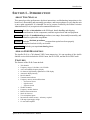
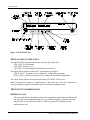
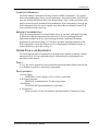
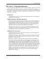
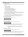
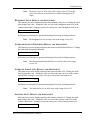
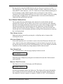
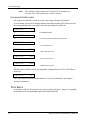
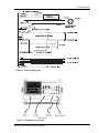
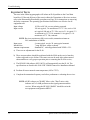
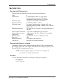
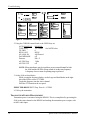
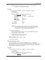
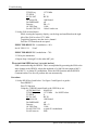
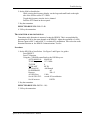
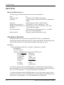
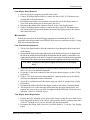
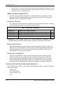
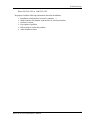
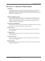
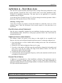
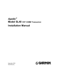
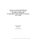
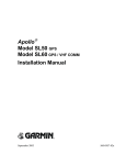
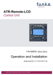
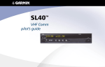
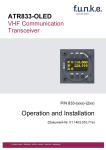
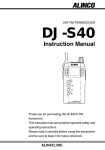
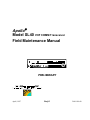
Apollo Model SL40 VHF COMM Transceiver Field Maintenance Manual PRELIMINARY April, 1997 Draft 3 560-1014-00 1997 by II Morrow Inc. All rights reserved. Printed in the USA No part of this document may be transmitted, reproduced, or copied in any form or by any means without the prior written consent of II Morrow Inc. Due to II Morrow’s commitment to constantly improve the quality and performance of our products, information contained in this document is subject to change without notice. II Morrow and Apollo are registered trademarks of II Morrow Inc. II Morrow Inc. PO Box 13549 Salem, OR 97309 Phone (503)581-8101 1-800-525-6726 In Canada 1-800-654-3415 FAX (503)364-2138 2345 Turner Rd. SE Salem, OR 97302 USA HISTORY OF REVISIONS Revision -- Date 4/8/97 Description Draft 3. ORDERING INFORMATION To receive additional copies of this publication, order part # 560-1014, Apollo SL40 VHF COMM Transceiver Field Maintenance Manual. REFERENCE PUBLICATIONS Following are other publications referenced in this guide. IPC 610A Acceptability of Electronic Assemblies 560-0956 Apollo Model SL40 VHF COMM Transceiver Installation Manual NOTES Table of Contents TABLE OF CONTENTS SECTION 1 - INTRODUCTION................................................................................................. 1 ABOUT THIS MANUAL ...................................................................................................................... 1 APOLLO SL40 DESCRIPTION ............................................................................................................. 1 FEATURES ......................................................................................................................................... 1 REGULATORY COMPLIANCE ............................................................................................................. 2 HANDLING CONSIDERATIONS ........................................................................................................... 2 ESD PROTECTION ..................................................................................................................................................... 2 COMPONENT HANDLING............................................................................................................................................ 3 SHIPPING CONSIDERATIONS....................................................................................................................................... 3 OTHER TOOLS AND EQUIPMENT ....................................................................................................... 3 TOOLS ....................................................................................................................................................................... 3 TEST EQUIPMENT ...................................................................................................................................................... 3 SECTION 2 - TROUBLESHOOTING ....................................................................................... 5 OVERVIEW ........................................................................................................................................ 5 ESD SAFE WORK AREA REQUIREMENTS ......................................................................................... 5 PRELIMINARY CHECKOUT................................................................................................................. 5 SYSTEM FUNCTIONS ......................................................................................................................... 6 SOFTWARE VERSION DISPLAY................................................................................................................................... 6 SIGNAL STRENGTH DISPLAY...................................................................................................................................... 6 AUDIO NOISE LEVEL DISPLAY................................................................................................................................... 6 HEADPHONE LEVEL DISPLAY AND ADJUSTMENT ...................................................................................................... 7 INTERCOM SQUELCH THRESHOLD DISPLAY AND ADJUSTMENT................................................................................. 7 INTERCOM AUDIO LEVEL DISPLAY AND ADJUSTMENT .............................................................................................. 7 SIDETONE LEVEL DISPLAY AND ADJUSTMENT .......................................................................................................... 7 BASE STATION LOCKOUT MODE DISPLAY AND ADJUSTMENT ................................................................................... 8 TEST MODE OPERATION ................................................................................................................... 9 TEST MODE ACCESS ................................................................................................................................................. 9 GENERAL OPERATION ............................................................................................................................................... 9 TEST MODE PAGE ..................................................................................................................................................... 9 DISPLAY TEST FUNCTION .......................................................................................................................................... 9 CONTROLS TEST FUNCTION .................................................................................................................................... 10 TEST SETUP .................................................................................................................................... 10 EQUIPMENT TESTS .......................................................................................................................... 12 TRANSMITTER ........................................................................................................................... 13 TRANSMITTER PERFORMANCE ................................................................................................................................ 13 TRANSMITTER FREQUENCY ERROR ......................................................................................................................... 13 TRANSMITTER POWER MEASUREMENT ................................................................................................................... 14 TRANSMITTER MODULATION ................................................................................................................................... 15 TRANSMITTER SNR (SIGNAL TO NOISE RATIO) ........................................................................................................ 16 TRANSMITTER AUDIO DISTORTION........................................................................................................................... 17 RECEIVER.................................................................................................................................... 17 RECEIVER PERFORMANCE ....................................................................................................................................... 18 SPEAKER AUDIO TEST...................................................................................................................................... 18 RECEIVER SENSITIVITY ................................................................................................................................... 19 UNIT DISASSEMBLY / REASSEMBLY ................................................................................................ 20 DISASSEMBLY ......................................................................................................................................................... 20 REASSEMBLY .......................................................................................................................................................... 21 Apollo SL40 Field Maintenance Manual i Table of Contents REPLACEABLE COMPONENTS ......................................................................................................... 22 COMPONENT LISTING............................................................................................................................................... 22 REPLACEMENT POLICY ............................................................................................................................................ 22 PACKAGING FOR SHIPMENT ..................................................................................................................................... 22 CONTACTING THE FACTORY FOR ASSISTANCE................................................................................ 22 SECTION 3 - CHECKOUT PROCEDURES .......................................................................... 25 GENERAL ....................................................................................................................................... 25 SERVICE VERIFICATION .................................................................................................................. 25 FUNCTIONAL CHECKOUT ................................................................................................................ 25 DISPLAY CHECK ...................................................................................................................................................... 25 CONTROLS TEST ...................................................................................................................................................... 25 TRANSMITTER TESTS ............................................................................................................................................... 25 RECEIVER TESTS ..................................................................................................................................................... 25 APPENDIX A - TEST DATA LOG .......................................................................................... 27 POST INSTALLATION CHECKOUT .................................................................................................... 27 SIDETONE LEVEL ADJUSTMENT ...................................................................................................... 27 FLIGHT TEST CHECK ...................................................................................................................... 27 LIST OF TABLES TABLE 1 REPLACEABLE COMPONENTS .......................................................................................... 22 LIST OF ILLUSTRATIONS FIGURE 1 SL40 FRONT PANEL ........................................................................................................ 2 FIGURE 2. TEST SETUP DIAGRAM ................................................................................................... 11 FIGURE 3. EQUIPMENT CONNECTION.............................................................................................. 11 FIGURE 4. TRANSMITTER TEST SETUP ............................................................................................ 14 FIGURE 5. RECEIVER TEST SETUP .................................................................................................. 19 FIGURE 6. COM MAIN BOARD OUTLINE ......................................................................................... 20 ii Apollo SL40 Field Maintenance Manual Introduction SECTION 1 - INTRODUCTION ABOUT THIS MANUAL This manual provides performance checkout instructions, troubleshooting instructions to the board level, disassembly and reassembly procedures, and test procedures to verify that the unit is once again operational. It is intended for use by persons certified by the Federal Aviation Administration (FAA) to repair aircraft communication devices. Section 1 Provides an introduction to the SL40 unit, details handling and shipping considerations for the components, and lists required tools and test equipment. Section 2 Includes all troubleshooting procedures, test setups, disassembly/reassembly, and identifies replaceable components. Section 3 Includes checkout procedures to ensure that repairs have been properly completed and unit is fully serviceable Appendix A Includes post repair test data log sheets. APOLLO SL40 DESCRIPTION The Apollo SL40 is a 760 channel VHF Comm transceiver. It is one member of the Apollo slimline series which includes the SL40 Comm, the SL50 GPS, and the SL60 GPS/Comm. FEATURES The features of the SL40 Comm include: • • • • • • • • • • • • • • • • 760 channels Frequency range of 118.000 to 136.975 MHz Active and standby frequency display 16 character high-intensity alphanumeric LED display Automatic display intensity Back-lit buttons Transmit status indicator Frequency memory and recall functions − from remote source − eight last used − eight user stored Weather channels Frequency monitor function Built-in intercom function Stuck mic time-out Two microphone inputs Internal non-volatile memory - no battery required Full range input supply voltage 12 watt audio amplifier Apollo SL40 Field Maintenance Manual 1 Introduction Figure 1 SL40 Front Panel REGULATORY COMPLIANCE The Apollo SL40 is designed and tested to meet the following TSOs: FAA TSO-C37d for transmit FAA TSO-C38d for receive FAA TSO-C128 for unintentional transmission (stuck mic) The Apollo SL40 complies with the FCC requirements specified in: CFR 47, Part 87, Aviation Services, Subpart D, Technical Requirements CFR 47, Part 15, Radio Frequency Devices, Subpart B, Unintentional Radiators The Apollo SL40 software is designed and tested to RTCA/DO-178B, level C. Note: Unauthorized changes or modifications to the SL40 may void the compliance to required regulatory agencies and authorization for continued equipment usage. HANDLING CONSIDERATIONS ESD PROTECTION The case on the SL40 is designed to protect the components from mechanical damage and also provides protection from damage due to electrostatic discharge. Open the case only when the unit is in an ESD safe work area. Observe proper ESD techniques when working on the unit. 2 Apollo SL40 Field Maintenance Manual Introduction COMPONENT HANDLING The SL40 contains electrostatic discharge sensitive (ESDS) components. Care must be taken when handling these devices to prevent damage. Special precautions for ESD work areas are detailed in ESD Safe Work Area Requirements, Page 5. Both you and the work surface must be properly grounded before handling the SL40 components. If moving the SL40 components from one area to another, they must either be reinstalled in the SL40 case or placed in an anti-static bag. SHIPPING CONSIDERATIONS All SL40 components must be returned to the factory in anti-static packaging equivalent to that used to ship the components from the factory. Save the packaging from the replacement components to use when returning the failed component. Packaging instructions are provided on Page 22. If you have questions regarding shipment of the SL40 components, contact the II Morrow Service Department. Information on how to contact the factory is provided on Page 22. OTHER TOOLS AND EQUIPMENT The following tools and test equipment (or equivalent) are required to properly evaluate and test the SL40. All test equipment must be calibrated before performing the test procedures in this manual. TOOLS A 3/32” hex tool is required to remove the SL40 from the mounting frame in the aircraft. A #2 Phillips screwdriver is required for disassembly TEST EQUIPMENT a. Power Supply: HP6433B DC Power Supply (0-36 V 0-10A) or equivalent b. RF Signal Generator: HP8920 RF Communications Test Set or equivalent c. Multimeter FLUKE 8010A Digital Multimeter or equivalent d. Test interface Refer to Figure 2 for the Test Interface schematic and SL 40 transceiver setup. Apollo SL40 Field Maintenance Manual 3 Introduction NOTES 4 Apollo SL40 Field Maintenance Manual Troubleshooting SECTION 2 - TROUBLESHOOTING This section provides information to assist in isolating problems with the SL40. Where required, detailed drawings of test setups are provided. The specified test equipment is a recommendation based on the equipment used to test the SL40 during manufacture and factory service. Alternate, but equivalent, equipment may be substituted if the recommended equipment is not available. OVERVIEW Field maintenance of the SL40 is limited to replacement of the SP96 Com Display Board and the VHF Com Main board. ESD SAFE WORK AREA REQUIREMENTS The SL40 circuit boards contain electrostatic discharge sensitive (ESDS) components. To prevent damage to the ESDS components, the circuit boards must be removed from the SL40 and handled in an ESD safe work area only. The work area must comply with the requirements of IPC 610A or other equivalent document. At a minimum, observe the following the following precautions when handling SL40 components. Both you and the work surface must be properly grounded before handling the SL40 components. If moving the SL40 components from one area to another, they must either be reinstalled in the SL40 case or placed in an anti-static bag. PRELIMINARY CHECKOUT Perform the following tests before removing the SL40 from the aircraft to determine if the problem is in the SL40 or the aircraft. Transmission and reception range is normally not a problem in aircraft due to the aircraft height above terrain. Poor reception range that can be traced to aircraft noise or antenna performance is usually repairable. The SL40 has a number of “System Functions” to assist in isolating Comm problems. Two of these features assist the operator or service personnel, in evaluating the aircraft communication environment: Signal Strength Display (RFLVL) and Audio Noise Level Display (NOISE). Additionally, there are several adjustments, which if improperly set, can give the appearance of a malfunctioning radio. If the system functions fail to pinpoint or correct a Comm problem remove the SL40 from the aircraft and refer to the Equipment Test procedures on Page 12 for bench testing. A built in Display test function allows isolation of Com Display board malfunctions with the SL40 mounted in the aircraft. If a problem is isolated to the SL40 (Com Display board or Com Main board) refer to the Disassembly procedures on Page 20 for instructions on removing and replacing the malfunctioning component. Apollo SL40 Field Maintenance Manual 5 Troubleshooting SYSTEM FUNCTIONS The following functions are available in the normal operating mode to assist in isolating problems: • • • • • • • • software version display signal strength display audio noise level display headphone level display and adjustment intercom squelch threshold display and adjustment intercom audio level display and adjustment sidetone audio level display and adjustment base station lockout mode display and adjustment The system functions are enabled by pressing the MON button for three seconds. The LED above the MON button will turn off. Rotate the LARGE knob to select the function. The software version page will be the initial display. The front panel buttons will operate normally during display of the system functions. Pressing any button will revert back to the normal mode defined for the button. The receiver will also operate normally during display of the system functions. SOFTWARE VERSION DISPLAY This function displays the COM software version. SW VER 1.0 SIGNAL STRENGTH DISPLAY This function is used to display the signal strength of received signals. RFLVL 087 With a dummy antenna connected, this function will normally be in the range 13 to 16. Full transceiver functions are operational during this function, including transmit. Note: The rf signal strength is an 8-bit value with a range of 0 to 255 from the IF/RF agc voltage as read into the µcontroller through an A/D input. AUDIO NOISE LEVEL DISPLAY This function is used to display the noise level of the received audio. NOISE 005 With a dummy antenna connected, this function will normally be in the range 162 to 170. Full transceiver functions are operational during this function, including transmit. 6 Apollo SL40 Field Maintenance Manual Troubleshooting Note: The noise level is an 8-bit value with a range of 0 to 255 from the noise level detector as read into the µcontroller through an A/D input. HEADPHONE LEVEL DISPLAY AND ADJUSTMENT This function is used to display and adjust the headphone audio level. Turning the small knob changes the value. Setting the value to 0 slaves the headphone audio level to the volume control knob. Setting to a non-zero value gives a fixed headphone audio level. HphLv 000 Full transceiver functions are operational during this function, including transmit. Note: The headphone level is an 8-bit value with a range of 0 to 255. INTERCOM SQUELCH THRESHOLD DISPLAY AND ADJUSTMENT This function is used to display and adjust the intercom squelch threshold level. Turning the small knob changes the threshold. IcmSq 200 Full transceiver functions are operational during this function, including transmit. Note: The intercom squelch threshold level is an 8-bit value with a range of 0 to 255. INTERCOM AUDIO LEVEL DISPLAY AND ADJUSTMENT This function is used to display and adjust the intercom audio level. Turning the small knob changes the value. Setting the value to 0 slaves the intercom level to the volume control knob. Setting to a non-zero value gives a fixed intercom audio level. IcmLv 000 Full transceiver functions are operational during this function, including transmit. Note: The intercom level is an 8-bit value with a range of 0 to 255. SIDETONE LEVEL DISPLAY AND ADJUSTMENT This function is used to display and adjust the sidetone audio level. Turning the small knob changes the value. Setting the value to 0 slaves the sidetone audio level to the volume control knob. Setting to a non-zero value gives a fixed sidetone audio level. SidLv 000 Apollo SL40 Field Maintenance Manual 7 Troubleshooting Full transceiver functions are operational during this function, including transmit. Note: The sidetone level is an 8-bit value with a range of 0 to 255. BASE STATION LOCKOUT MODE DISPLAY AND ADJUSTMENT This function is used to display and adjust the lockout mode. Improperly set, the lockout can disable various Comm functions giving the appearance of a malfunctioning unit. Turning the small knob changes the mode. The modes are summarized as follows. Locks • Mode 0: 000 Normal pilot mode. No disabled functions • Mode 1 & 3: Toggle Lock. Only the Flip-Flop button is disabled. Fixed Primary frequency. Variable Standby frequency. Frequencies cannot be swapped. • Mode 2 & 6: Primary Frequency Protected. Fixed Primary frequency. Variable Standby frequency. Frequencies can be swapped. Primary is not modifiable when it is the standby freq. (displayed as Mode 6) • Mode 4: Fixed Two Channel radio. Both frequencies are fixed. Frequencies CAN be swapped. • Mode 5 & 7: Toggle Lock w/ fixed standby frequency. Both frequencies are fixed. Frequencies CANNOT be swapped. Note that it is possible to put the unit into mode 8, but on re-entry to the system functions, it will be show as mode 0. Full transceiver functions are operational during this function, including transmit. Note: The lockout mode has a range of 000 to 008. While viewing the frequency display, use the large and small knobs on the right side of the SL40 to select an unused local channel. Toggle this frequency to the active channel. Press and hold the MON button for about 3 seconds to reach the System Function. Use 8 Apollo SL40 Field Maintenance Manual Troubleshooting the large knob to select the NOISE function and view the receive noise level of the selected frequency. The value will change constantly, and has a range between 0 and 255 and an RFLVL in the mid teens (14 to 17). On the service bench with the antenna port of the SL40 dummy loaded, NOISE should be between 100 and 125. If the SL40 is connected to the aircraft antenna and there is no carrier on the channel, expect the reading to be the same or slightly lower. To confirm that there is no carrier on the monitored channel pull the squelch knob and listen. TEST MODE OPERATION The test mode allows the SL40 display and controls to be tested with the unit still mounted in the aircraft. The test mode is also used to access certain test and calibration functions used during manufacture and at the service center. Do not change or adjust any functions accessed in the test mode unless specific instructions are provided in this manual. If the SL40 fails either the Display or Controls test, remove the unit from the aircraft and refer to the Disassembly procedures on Page 20 for instructions on removing the Com Display board. TEST MODE ACCESS Enable the built-in test mode by pressing the ⇔ (flip/flop) and RCL buttons while switching the unit on. GENERAL OPERATION In test mode operation, the LARGE knob is used to select the different test functions, the SMALL knob is used to select additional pages for each test function. In general, the only test functions that will be used at the Field Maintenance level are the Display test and the Controls test. Do not modify any setting displayed while in the test mode. TEST MODE PAGE The “Test Mode Page” is the first page displayed in the test mode TEST MODE When this page is displayed, pressing the MEM button will return the COM to normal mode operation. DISPLAY TEST FUNCTION This function is used to test the display and LED indicators. DISPLAY TEST Press the MEM button to execute the display test. The display will sequence through the test by turning on the first four characters, the 2nd four, the 3rd four, and then the last four characters. Once the sequence is complete, “DISPLAY TEST” will be displayed. Apollo SL40 Field Maintenance Manual 9 Troubleshooting Note: This function will not turn on all 35 dots on all 16 characters at the same time. This would cause excessive current. CONTROLS TEST FUNCTION The controls test function is used to test the control inputs from the front panel. As each button is pressed, the display indicates the button and the LED is turned on over the corresponding button. SQ displays when the squelch knob is pulled out. CONTROLS <-> ⇔ button pressed TX CONTROLS SQ <-> ⇔ button pressed and squelch knob pulled out TX CONTROLS EC “EC” button pressed CONTROLS MON “MON” button pressed CONTROLS RCL “RCL” button pressed CONTROLS MEM “MEM” button pressed When the SMALL knob is turned, the magnitude is displayed (000 to 255). All LEDs are turned off. CONTROLS 045 The LARGE knob is not tested in this function. It is tested by default by selecting the various test functions. TEST SETUP A schematic of the SL40 transceiver test setup is shown in Figure 2. Figure 3 is a graphic presentation of the recommended equipment connected for test. 10 Apollo SL40 Field Maintenance Manual Troubleshooting Figure 2. Test Setup Diagram Figure 3. Equipment Connection Apollo SL40 Field Maintenance Manual 11 Troubleshooting EQUIPMENT TESTS The tests in the following paragraphs will isolate an SL40 problem to the Com Main board level. If the unit fails any of the tests in either the Transmitter or Receiver sections, refer to the Disassembly/Reassembly procedures on Page 22 for instructions on removing the faulty component. The operating specifications listed below are effective for all equipment tests. Input voltage Input current 10 Vdc to 40 Vdc, reverse polarity protected 300 mA typical, 2 A maximum at 13.75 V dc, receive 140 mA typical, 900 mA at 27.5 Vdc, receive 2.1 A typical, 3.2 A maximum at 13.75 Vdc, transmit 1.0 A typical, 1.4 A maximum at 27.5 Vdc, transmit NOTE: Receiver maximum at full receive audio, transmit maximum at 90% modulation at 1000Hz. Input power 4 watts typical, receive 28 watts typical transmit. Internal fuse 7 amp fast blow, solder on board. Antenna requirements Standard 50Ω vertically polarized with VSWR <2.5:1. a) There are no adjustments for the SL40. b) These test procedures should be performed with the SL40 on the service bench to isolate suspected service failures. The same tests can be used after replacement of subassemblies to verify proper operation prior to returning the SL40 to service,. c) The HP 8920 AM software (HP 11807A) will automatically test the SL 40. The specifications are listed in the SL40 VHF COMM Transceiver Installation Manual. d) Perform all tests at normal room temperature (68° to 72° F). e) Complete the transmitter frequency test before performance evaluating the receiver. NOTE: All RF voltages are "HARD" Micro volts. "Hard" micro volts indicates use of a 6 dB pad between the signal generator and the receiver. When using the HP 8920 “HARD” should be set in the test equipment configuration MENU. 12 Apollo SL40 Field Maintenance Manual Troubleshooting TRANSMITTER TRANSMITTER PERFORMANCE The following specifications define expected transmitter performance. Class Output Power Frequency range Frequency tolerance Microphone input Modulation capability Audio frequency distortion Audio frequency response Carrier noise Sidetone output Duty cycle Stuck Mic time-out Transmit key 4 8 watts minimum carrier at 12 VDC input. 6 watts minimum carrier at 10 VDC input. The transmit is lock out below 9 VDC input 118.000 to 136.975 MHz, 750 channels ±15 PPM from 20°C to + 70°C Two inputs, standard carbon or dynamic MIC with integrated preamp providing minimum 70 mV rms into 1000Ω load. 85% with 100 mV to 1000 mV rms microphone input at 1000 Hz. <10% at 85% modulation at 350 to 2500 Hz. <4dB variation with 350 to 2500 Hz, 85% modulation. >35dB down up to 280 mW into 100Ω, 120 mW into 500Ω. 100% 35 seconds, reverts to receive. Input pull low to enable transmitter TRANSMITTER FREQUENCY ERROR Transmitter Frequency error is measured using the HP 8920. This is accomplished by presetting the SL40 to the same channel as the HP8920 and reading the frequency error from the HP8920 Communications Test Set. NOTE: Set the DC supply voltage to 13.75 volts ± 0.75 volts prior to performance evaluating the transmitter. Procedure: 1. Set the HP 8920 as listed below. Use Figure 3 and Figure 4 as guides. Press PRESET Press TX function Apollo SL40 Field Maintenance Manual 13 Troubleshooting Figure 4. Transmitter Test Setup 2. Using the CURSOR control knob or the USER keys set: AUTO MANUAL MANUAL TUNE Freq 127.5 MHz See NOTE below TX PWR 0 RF IN/ ANT RF IN AF ANAL IN AM Demod De-EMPHASIS off Detector PK+-/2 AF GEN Freq. 1 kHz AF GEN LVL off NOTE: Where interference may be a problem, use any unused channel for both the SL40 and the HP 8920 as long as both are on the same frequency. A frequency close to center of operating range is preferred. 3. Set the SL40 as listed below. While viewing the frequency display, use the Large and Small knobs on the right side of the SL40 to select 127.5 MHz. Toggle this frequency into the Active channel. Press the PTT button on the test panel. EXPECTED RESULTS TX Freq. Error 0 ± 15 PPM 4. UN-key the transmitter TRANSMITTER POWER MEASUREMENT Transmitter power is measured using the HP8920. This is accomplished by presetting the SL40 to the same channel as the HP8920 and reading the transmitter power output, with no MIC audio input. 14 Apollo SL40 Field Maintenance Manual Troubleshooting NOTE: Set the DC supply voltage to 13.75 volts ± 0.75 volts prior to performance evaluating the transmitter. Procedure: 1. Set the HP 8920 as listed below. Use Figure 3 and Figure 4 as guides. Press PRESET Press TX function Using the CURSOR control knob or the USER keys set: AUTO MANUAL MANUAL TUNE Freq 127.5 MHz See NOTE below TX PWR 0 RF IN/ ANT RF IN AF ANAL IN AM Demod De-EMPHASIS off Detector PK+-/2 AF GEN Freq 1 kHz AF GEN LVL off NOTE: Where interference may be a problem, use any unused channel for both the SL40 and the HP 8920 as long as both are on the same frequency. A frequency close to center of operating range is preferred. 2. Set the SL40 as listed below. While viewing the frequency display, use the large and small knob on the right side of the SL40 to select 127.5 MHz. Toggle this frequency into the Active channel. Press the PTT button on the test panel. EXPECTED RESULTS: TX PWR > 8 watts 3. UN-key the transmitter TRANSMITTER MODULATION Transmitter modulation is measured using the HP8920. This is accomplished by presetting the SL40 to the same channel as the HP8920; inputting a 1000 Hz tone at 50 to 100 mV at MIC 1 and/or MIC 2; and reading the transmitter percentage of modulation from the HP8920 Communications Test Set. Procedure: 1. Set the HP 8920 as listed below. Use Figure 3 and Figure 4 as guides. Press PRESET Press TX function Using the CURSOR control knob or the USER key’s set: AUTO MANUAL MANUAL Apollo SL40 Field Maintenance Manual 15 Troubleshooting TUNE Freq TX PWR RF IN/ ANT AF ANAL IN De-EMPHASIS Detector AF GEN Freq Set AF GEN LVL 127.5 MHz 0 RF IN AM Demod off PK+-/2 1 kHz 100 mV and to on 2. Set the SL40 as listed below: While viewing the frequency display, use the large and small knob on the right side of the SL40 to select 127.5 MHz. Toggle this frequency into the Active channel. Press the PTT button on the test panel. EXPECTED RESULTS % modulation > 90% Set AF GEN. LVL 50 mV EXPECTED RESULTS % modulation > 70% 3. UN key the transmitter. 4. Repeat Steps 1 through 3 for the other MIC jack. TRANSMITTER SNR (SIGNAL TO NOISE RATIO) SNR is measured using the HP8920. This is accomplished by presetting the SL40 to the same channel as the HP8920. Adjust the amplitude of a 1000 Hz tone (input to MIC 1 and/or MIC 2) to obtain 85% modulation. Select the SNR function and the HP8920 Communications Test Set will perform this test automatically. Procedure: 1. Set the HP 8920 as listed below. Use Figure 3 and Figure 4 as guides. Press PRESET Press TX function Using the CURSOR control knob or the USER keys set: AUTO MANUAL MANUAL TUNE Freq 127.5 MHz See NOTE below TX PWR 0 RF IN/ ANT RF IN AF ANAL IN AM Demod De-EMPHASIS off Detector PK+-/2 AF GEN Freq 1 kHz Set AF GEN LVL to read 85% modulation Set AF meter to SNR 16 Apollo SL40 Field Maintenance Manual Troubleshooting 2. Set the SL40 as listed below: While viewing the frequency display, use the large and small knob on the right side of the SL40 to select 127.5 MHz. Toggle this frequency into the Active channel. Press the PTT button on the test panel. 3. Key the transmitter EXPECTED RESULTS SNR ≥35 dB 4. UN key the transmitter TRANSMITTER AUDIO DISTORTION Transmitter audio distortion is measured using the HP8920. This is accomplished by presetting the SL40 to the same channel as the HP8920. Adjust the amplitude of a 1000 Hz tone (input to MIC 1 and/or MIC 2) to obtain 85% modulation. Then select the audio distortion function on the HP8920 Communications Test Set. Procedure: 1. Set the HP 8920 as listed below. Use Figure 3 and Figure 4 as guides. Press PRESET Press TX function Using the CURSOR control knob or the USER keys set: AUTO MANUAL MANUAL TUNE Freq 127.5 MHz TX PWR 0 RF IN/ ANT RF IN AF ANAL IN AM Demod De-EMPHASIS off Detector PK+-/2 AF GEN Freq 1 kHz Set AF GEN LVL to read 85% modulation Set AF meter to DISTN 2. Key the transmitter EXPECTED RESULTS: DISTN < 10% 3. UN key the transmitter Apollo SL40 Field Maintenance Manual 17 Troubleshooting RECEIVER RECEIVER PERFORMANCE The following specifications define expected receiver performance. Class Frequency range Sensitivity D 118.000 to 136.975 MHz, 760 channels. 1µV (2µV hard) for 6dB S+N/N with 30% modulation at 1000Hz Selectivity <6dB variation at ±7kHz > 60dB at 22kHz Speaker audio output level 12 watts into 4Ω load., 8 watts into 8Ω load. Headphone audio output level 280mW into 100Ω load, 120 mW into a 500Ω load. Distortion <5% at rated audio output. AGC characteristics <3dB variation in audio output from 5 µV to 100mV input, 15% to 90% modulation. Squelch control Automatic squelch with manual override SPEAKER AUDIO TEST The speaker audio level is measured using the HP8920. This is accomplished by connecting the speaker audio to the Audio in, (high) of the HP8920. By adjusting volume control to the desired level, (12W) and measuring the audio power in watts. Procedure 1. Set the HP 8920 as listed below. Use Figure 3 and Figure 5 as guides. Press PRESET Press RX function Using the CURSOR control knob or the USER keys set: AUTO MANUAL MANUAL RF GEN Freq 127.50 MHz AF GEN Freq 1 kHz Amplitude 10,000 µ volts RF OUTPUT RF OUTPUT AF Freq 1000 / 85% Ext Load 4 ohms AC LEVEL units to Watts 2. Connect the speaker load to the HP8920 audio in. Turn the SL40 volume control to show an output level of 12 watts on the HP8920. Record the Speaker 1000 Hz Distortion at 12 watts. Value should be < 5%. Set the distortion level to Reference 3. Connect the headset load to the HP8920 audio in. Turn SL40 volume control to show an output level of 280 m watts on the HP8920. Record the Headset 1000 Hz Distortion at 280 m watts. Value should be < 5%. Set the distortion level to Reference 18 Apollo SL40 Field Maintenance Manual Troubleshooting Figure 5. Receiver Test Setup RECEIVER SENSITIVITY The speaker audio level is measured using the HP8920. Procedure 1. Set the HP 8920 as listed below. Use Figure 3 and Figure 5 as guides. Press PRESET Press RX: function Using the CURSOR control knob or the USER keys set: RF GEN Freq 118.00 MHz Amplitude 1,000 µ volts RF OUTPUT RF OUTPUT AF Freq 1,000 / 85% Ext Load 4 ohms AC LEVEL W 2. Connect speaker load to the HP8920 audio in. Set SINAD low level to 4 dB (LO=4). Turn SL40 volume control until AC LEVEL on HP8920 reads 12 watts. 3. The distortion level on the HP8920 should be < 5%. 4. Reduce the AF Freq. modulation level on the HP8920 to 30 The distortion level on the HP8920 should be < 5% and the noise level should be ≥ 25 dB. 5. Disable the squelch by pulling out on the volume knob. Reduce the signal generator amplitude until the HP8920 displays a 6 dB SINAD value (S+N/N). The amplitude level should be <1 volt. Apollo SL40 Field Maintenance Manual 19 Troubleshooting UNIT DISASSEMBLY / REASSEMBLY DISASSEMBLY Perform the procedures in the following paragraphs to disassemble the SL40. All disassembly must be performed in an ESD safe work area (see guidelines on Page 5) using ESD safe working techniques. Com Main Board Removal 1. Place the SL40 on a properly grounded work surface. 2. Using a #2 Phillips head screwdriver, remove the nine 4-40x3/16” flat head screws securing the cover to the chassis. 3. Lift the back end of the cover and slide it towards the rear of the chassis until it is clear of tab on the display bezel, then remove the cover. 4. Disconnect the ribbon cable connector from J603 on the Com Main board. 5. Using a #2 Phillips head screwdriver, remove the ten 4-40x1/4” panhead screws and lockwashers securing the Com Main board to the chassis. 6. Using a #2 Phillips head screwdriver, remove the two 4-40x1/4” flathead screws securing the 15-pin d-sub connector to the back of the chassis. 7. Using a 9/16” deep well socket, remove the jam nut and internally toothed lockwasher securing the BNC connector to the back of the chassis. 8. With the board positioned tightly against the back of the chassis, tilt up the front of the board until it is clear of the bezel then slide the board forward to remove it from the chassis. NOTE: There is a small notch in the upper right corner of the Com Main board (See Figure 6 ) that allows the board to just clear the tab on the display bezel when the board is properly positioned. If more that a very slight forward pressure on the bezel is required to remove the Com Main board, check the position of the board in the chassis and ensure that the notch is aligned with the tab on the bezel. NOTCH COM MAIN BOARD Figure 6. Com Main Board Outline CAUTION: Do not force the board or apply excessive force to the display bezel. 20 Apollo SL40 Field Maintenance Manual Troubleshooting Com Display Board Removal 1. Place the SL40 on a properly grounded work surface. 2. Using a #2 Phillips head screwdriver, remove the nine 4-40x3/16” flat head screws securing the cover to the chassis. 3. Lift the back end of the cover and slide it towards the rear of the chassis until it is clear of tab on the display bezel, then remove the cover. 4. Disconnect the ribbon cable connector from J1 on the Com Display board. 5. Using a #2 Phillips head screwdriver, remove the three 4-40x1/4” flat head screws (one on each side and one on the bottom) that secure the display bezel to the chassis and remove the bezel. REASSEMBLY Perform the procedures in the following paragraphs to reassemble the SL40. All reassembly must be performed in an ESD safe work area (see guidelines on Page 5) using ESD safe working techniques. Com Main Board Replacement 1. Tilt the Com Main board to allow the connectors to go through the holes in the back of the chassis. 2. Ensure that the notch in the upper right corner of the board (see Figure 6) is aligned with the tab on the display bezel and push the board down into the chassis. If more that a very slight forward pressure on the bezel is required to replace the Com Main board, reposition of the board in the chassis and ensure that the notch is aligned with the tab on the bezel. CAUTION: Do not force the board or apply excessive force to the display bezel. 3. Ensure that the holes in the board are aligned with the matching holes in the chassis. Start 1 or 2 screws to maintain alignment. 4. Secure the 15-pin d-sub connector to the rear of the chassis using two 4-40x1/4” flat head screws. 5. Using a 9/16” deep well socket, fasten the BNC connector to the rear of the chassis with a nut and internally toothed lockwasher. 6. Secure the Com Main board to the chassis using ten 4-40x1/4” pan head screws and lockwashers. 7. Reconnect the ribbon cable from the display board to J603 on the Com Main board. 8. Tilt the SL40 cover so the front edge slides under the tab on the display bezel, and position the cover so the screw holes are aligned with the PEM nuts. Secure the cover with nine 4-40x3/16” flat head screws. Com Display Board Replacement 1. Position the bezel assembly on the front of the chassis so that the screw holes in the bezel align with the holes in the chassis, and secure the bezel in position using three 4-40x1/4” flat head screws, one on each side and one on the bottom. 2. Reconnect the ribbon cable from the Com Main board to J1 on the Com Display board. Apollo SL40 Field Maintenance Manual 21 Troubleshooting 3. Tilt the SL40 cover so the front edge slides under the tab on the display bezel, and position the cover so the screw holes are aligned with the PEM nuts. Secure the cover with nine 4-40x3/16” flat head screws. REPLACEABLE COMPONENTS The SL40 field replaceable components are listed by II Morrow part number in Table 1. Replacement policy and information on proper packaging of the SL40 components for shipment is given in subsequent paragraphs. COMPONENT LISTING The components of the SL40 that are considered to be field replaceable and for which test and replacement procedures are provided are listed in Table 1. Table 1 Replaceable Components 430-6040-2xx Part # *415-7000-10 415-7002-00 Apollo SL40 Comm Transceiver Description SP96 Com Display Board 6010 VHF Com Main Board 6011 Qty 1 1 *Although the Com Display board is the actual replaceable component, assembly considerations dictate that the complete Display assembly be returned for replacement. REPLACEMENT POLICY When troubleshooting procedures identify a failed component in the SL40, contact the II Morrow Service Department for a Return Material Authorization (RMA) number and shipping instructions. Do not return the component without an RMA. Instructions for contacting the factory are given on page 22 PACKAGING FOR SHIPMENT The SL40 circuit boards are subject to both mechanical and electrical damage when improperly handled. These components must be packaged for shipment in anti-static bags, to protect against electrostatic damage, and a sturdy protective box, to prevent mechanical damage during shipment. Ideally, the component to be returned should be packaged in the same shipping material that the replacement component is shipped in. CONTACTING THE FACTORY FOR ASSISTANCE If the Apollo SL40 unit fails to operate despite troubleshooting efforts, contact the II Morrow factory for assistance. II Morrow Inc. 2345 Turner Rd. SE Salem, Oregon 97302 USA 22 Apollo SL40 Field Maintenance Manual Troubleshooting Phone (503)581-8101 or 1-800-525-6726 Be prepared with the following information about the installation: • Installation configuration (accessories, antenna, ...) • Model number, part number with mod levels, and serial number • Software versions • Description of problem • Efforts made to isolate the problem • other installed avionics Apollo SL40 Field Maintenance Manual 23 Troubleshooting NOTES 24 Apollo SL40 Field Maintenance Manual Checkout Procedures SECTION 3 - CHECKOUT PROCEDURES GENERAL This Section provides procedures for final verification and checkout of the SL40 prior to returning the unit to service. During the checkout, the Test Data Sheet described in Appendix A is to be filled out. If all items check out properly, the unit may be reinstalled in the aircraft and returned to service. SERVICE VERIFICATION Verify that unit has been repaired properly, all components have been reinstalled and properly secured, and that all functions are set as required. Note the date the repairs were completed, components replaced, technician who performed the repair and any other pertinent details on the Test Data Sheet. FUNCTIONAL CHECKOUT After replacement of the faulty component and before reinstalling the SL40 in the aircraft, retest the unit to ensure that all functions are operating properly. DISPLAY CHECK Perform the display test given on Page 9. Record the test results on the Test Data Log sheet in Appendix A. CONTROLS TEST Perform the controls test given on Page 10. Record the test results on the Test Data Log sheet in Appendix A. TRANSMITTER TESTS Perform the transmitter tests beginning on Page 13. Record the test results on the Test Data Log sheet in Appendix A. RECEIVER TESTS Perform the receiver tests beginning on Page 17. Record the test results on the Test Data Log sheet in Appendix A. Apollo SL40 Field Maintenance Manual 25 Checkout Procedures NOTES 26 Apollo SL40 Field Maintenance Manual Appendix A APPENDIX A - TEST DATA LOG Once the unit is repaired and the checkout procedure on Page 25has been performed to verify proper operation, reinstall the SL40 in the aircraft. Refer to the SL40 Installation Guide, 560-0956 for installation instructions. The steps that are not applicable to a particular installation may be skipped. A test data log sheet is included on page 27 to fill out during the checkout procedure. Make a photocopy of the log sheet for ease of use if desired. Mounting / Wiring Check Verify that all cables are properly secured and shields are connected to the rear of the mounting frame. Check the movement of the aircraft controls to verify that there is no interference. POST INSTALLATION CHECKOUT Once the unit is reinstalled, complete the post installation checkout procedure given in the SL40 Installation Guide, 560-0956 to verify proper operation. Refer to the Users Guide for operating instructions. SIDETONE LEVEL ADJUSTMENT The sidetone volume was preset at the factory to what should be an acceptable level. However, the level can be adjusted using the built-in test mode. To adjust the sidetone level: 1. Press and hold the ⇔ and RCL buttons while switching on the unit. This will enable the built-in test mode. 2. Rotate the LARGE knob to display the SIDETONE LVL page. 3. Press the ⇔ (the number will flash), rotate the small knob to change the level number, and press MEM to save the new setting. The range of the number is 000 to 255, with 128 producing one half of full rated output. 4. Turn the unit off to exit the test mode. 5. Turn on the unit, select an appropriate frequency, and key the transmitter and talk into the microphone to check the level. FLIGHT TEST CHECK A flight test is recommended as a final installation verification. The performance may be verified by contacting a ground station at a range of at least 50nm while maintaining an appropriate altitude and over all normal flight attitudes. Performance should be checked using low, high, and mid band frequencies. APOLLO SL40 POST-REPAIR TEST DATA LOG Apollo SL40 Field Maintenance Manual Date: ___/___/___ 27 Appendix A By: _____________ CONFIGURATION INFORMATION: SL40 VHF COMM 430-6040-2__ Mod ____ DISPLAY AND CONTROLS CHECKOUT OK Display test Controls OK ⇔ Button test OK Squelch knob test OK EC Button test Serial # ___________ Antenna: ___________ OK MON Button test OK RCL Button test OK MEM Button test TRANSMITTER CHECKOUT: Transmitter Frequency Error PPM @ MHz ( < 15 PPM) Transmitter Power Watts @ MHz (> 8 Watts) Transmitter Modulation @ 100 mV MIC 1 %@ MHz (> 90%) Transmitter Modulation @ 50 mV MIC 1 %@ MHz (> 70%) Transmitter Modulation @ 100 mV MIC 2 %@ MHz (> 90%) Transmitter Modulation @ 50 mV MIC 2 %@ MHz (> 70%) Transmitter SNR dB @ MHz (≥ 35dB) Transmitter Audio Distortion %@ MHz (< 10%) RECEIVER CHECKOUT: Speaker Audio Distortion % (< 5%) Receiver Sensitivity: Distortion % (<5%) Headset Audio Distortion % (< 5%) Noise dB (≥ 25dB) Ampl. µvolts (<1µv) COMMENTS: NOTES 28 Apollo SL40 Field Maintenance Manual