1
GPS Field guide
© WHO 2002
09/25/02
GPS_field_guide
8:19 A9/P9
CONTENTS
CHAPTER 1: INTRODUCTION TO GPS
1.1 What is GPS ?…………………………………………………………...2
1.2 How does GPS work ?…………………………………………………..3
1.3 Source of GPS signal errors……………………………………………...7
CHAPTER 2: WHY USING GPS IN THE CONTEXT OF THE WHO WHS ?
CHAPTER 3: PRESENTATION OF THE GARMIN ETREX GPS UNIT
3.1 Overview of the eTrex unit……………………………………………..10
3.2 Utilisation of the eTrex unit…………………………………………….13
3.2.1 Installation of the batteries………………………………………….13
3.2.2 The eTrex operating system………………………………………...13
3.2.3 The eTrex pages……………………………………………………..14
3.2.3.1 The 'NORMAL SKYVIEW SATELLITE' page………………...14
The 'DISPLAY' page………………………………………………..16
The 'ADVANCED SKYVIEW SATELLITE' page………………...17
3.2.3.2 The 'MENU' page………………………………………………..17
The 'MARK WAYPOINT' option page…………………………….19
The 'SETUP' option page……………………………………………19
The 'UNITS' setup page…………………………………………….20
The 'SYSTEM' setup page………………………………………….20
CHAPTER 4: TROUBLESHOOTING
4.1 eTrex doesn't turn on…………………………………………………….21
4.2 The message "READY TO NAVIGATE" doesn't appears on the screen 21
4.3 The message "TROUBLE TRACKING SATELLITES. ARE YOU
INDOOR NOW ?" appears on the screen…………………………..21
4.4 I am not getting an accuracy higher (better) than 20 meters…………….22
4.5 eTrex does not display the desired units when making the accuracy or
coordinates reading………………………………………………….22
4.6 eTrex does not display the local time on the 'SETUP' page…………….23
4.7 The geographic coordinates I get are outside the ranges given in the
protocol form……………………………………………………….23
GLOSSARY………………………………………………………………………….24
BIBLIOGRAPHY / LINKS………………………………………………………….25
2
09/25/02
GPS_field_guide
8:19 A9/P9
CHAPTER 1: INTRODUCTION TO GPS
1.1 What is GPS?
The Global Positioning System (GPS) is a system allowing to precisely identify locations
on the earth's surface.
The GPS system has 3 parts (Figure 1):
·
·
·
The Space segment: a network of 24 satellites placed into orbit (Figure 2). The first
GPS satellite was launched in 1978 and a full constellation of 24 satellites was
achieved in 1994. Each satellite is built to last about 10 years. Replacements are
constantly being built and launched into orbit.
The Control segment which consists of ground stations, located around the world that
make sure the satellites are working properly.
The User segment: the GPS receivers used by the community (eg. ETrex device).
Figure 1 : The 3 GPS segments
This satellite-based system offers highly precise location data for any point on the planet,
in any weather conditions, 24 hours a day. It is mainly used for navigation, positioning
and other research applications.
3
09/25/02
GPS_field_guide
8:19 A9/P9
1.2 How does GPS work?
GPS satellites circle the Earth twice a day in a very precise orbit at an altitude of around
19 000 Kilometres (Figure 2). This constellation allows any user to access between five
and eight satellites from any point on the Earth.
Figure 2: The GPS Satellite network
Each satellite transmits radio signal information which is tracked and used by the GPS
receiver to calculate the user's exact location.
The satellite signal:
This constantly transmitted radio signal passes through clouds, glass and plastic but
not through most solid objects such as buildings and mountains.
A GPS signal contains three kinds of coded information essential for determining a
position:
· An I.D. that identifies each of the 24 satellites of the network
· The almanac data that contains the orbital information for all satellites in the system.
· The ephemeris data, which contains important information about the status of the
satellite (healthy or unhealthy), and the current date and time.
To determinate precise latitude and longitude/position, the receiver measures the
travelling time of the signal between the satellites and itself and transform it into a
distance.
4
09/25/02
GPS_field_guide
8:19 A9/P9
The receiver:
1. Calculates the distance to the first satellite he is able to catch. Let's suppose that the
receiver calculates a distance of 17'000 km between this first satellite and the receiver.
This will mean that the receiver is located somewhere on a sphere that is centred on this
first satellite and that has a radius of 17'000 km (Figure 3).
Figure 3 - Sphere indicating the potential location of the GPS receiver with one
satellite signal
2. Calculates the distance to a second satellite for which it is able to catch a signal
(19'000 km for example). This tells the receiver that it is not only located on the first
sphere (Figure 3) but also on a second sphere centred on the second satellite and that has
a radius of 19'000 km. Or in other words, that the receiver is somewhere on the circle
where these two spheres intersect (Figure 4 point a).
Figure 4 - Circle indicating the potential location of the GPS with two satellite signals
(a)
5
09/25/02
GPS_field_guide
8:19 A9/P9
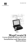
3. Repeats the operation mentioned under point 2 with a third satellite. In our example
the receiver finds out that it is 20,000 km from the third satellite which narrows its
position down even further, to the two points (Figure 5 point b) where the 20,000 km
sphere cuts through the circle reported on Figure 4 (corresponding to the intersection
of the first two spheres).
Figure 5 - Potential locations of the GPS receiver with 3 satellites signals (b)
Most of the time one of these two points is absurd and is rejected by the receiver that
is then able to give the exact location. In some cases, a fourth satellite is necessary to
know which of the two points is the correct one. In any case, a configuration with 4
satellites is better in order to increase the accuracy and/or reduce the sources of error.
6
09/25/02
GPS_field_guide
8:19 A9/P9
1.3 Sources of GPS signal errors
Even if today's GPS receivers are extremely accurate, certain atmospheric factors and
other sources of error can affect the accuracy of GPS receivers.
If most of the sources of error are unavoidable, it is important for the user to be aware of
the ones that he can influence and be prepared to take steps to reduce their impact.
The greatest source of error is connected to the position of the satellite in the sky when
taking the measurement. The spread of the satellites in the sky is called the Positional
Dilution of Precision (PDOP). A good PDOP is obtained when the satellites are located
at wide angles relative to each other (Figure 6 a). In the contrary, a poor PDOP result
from satellites being located in a line or in a tight grouping (Figure 6 b).
b)
a)
Figure 6: a) Good PDOP b) Poor PDOP
The second source of error comes from the infrastructure (buildings, bridges) and
particular landform (mountains) that are located around the receiver. These objects can
block the reception of the signal (Figure 7), causing position errors or possibly no
position reading at all.
a
b
a
b
Figure 7 - Example of good visibility (a)
and bad visibility (b) of satellites due to obstacles
GPS units typically will not work indoors, underwater or underground.
7
09/25/02
GPS_field_guide
8:19 A9/P9
There may also be sources of signal multipath (i.e on Figure 8) occurring when the GPS
signal is reflected off these objects before reaching the receiver. This increases the travel
time of the signal and creates errors of distance estimation between the satellite and the
receiver.
1
·
2
1
2
Figure 6 Examples of signal multipath
Figure 8 - Example of multipath GPS signal connected to buildings or mountains
This underlines the importance for the users to be located in the most open area as
possible before taking the measurement.
There are other sources of error over which the user does not have control, including:
· Atmosphere delays — The satellite signal slows as it passes through the
atmosphere. The GPS system uses a model that calculates an average amount of
delay to correct for this type of error.
· Receiver clock errors — A receiver's built-in clock is not as accurate as the
atomic clocks onboard the GPS satellites. Therefore, it may have very slight
timing errors.
· Orbital errors — Also known as ephemeris errors, these are inaccuracies of the
satellite's reported location.
8
09/25/02
GPS_field_guide
8:19 A9/P9
CHAPTER 2: WHY USING GPS IN THE CONTEXT OF
THE WHO WHS ?
The first reason for using GPS in the WHS context is the added value it gives to the
survey by allowing the geographical dimension to be taken into account without
requiring important investment (many GPS receivers are inexpensive, GPS data is free,
and survey staff can be trained quickly to their use).
By knowing the geographic location of each cluster it will be, for example, easier to go
back to the same place for supplementary data collection.
With the geographic location it is also possible to use the information collected by the
receiver within the Geographic Information Systems (GIS). A GIS can be defined as
being a computer system for capturing, storing, checking, integrating, manipulating,
analysing and displaying data related to a position on a surface (AGI dictionary).
By integrating the location of the WHS clusters into a GIS it will firstly be possible :
- to examine the relationship that may exists between the data collected and the
infrastructure located within or around the clusters. This concerns, for example,
health facilities, roads, market, water pumps and so on. If the location of these is
known, the GIS tool will be used to calculate the distance to the nearest
infrastructure and include this information into the survey analysis.
- to extract figures at the cluster level from other spatially distributed information
such as Digital Elevation Models (altitude), environmental parameters (climates,
landuse,…) and use them in multivariable analysis.
- to aggregate the clusters according to new units of analysis, such as climatic
zones or ethnic regions.
- to extrapolate some of the figures collected by the survey using other
geographically distributed parameters which include modelling capabilities.
With all this information being implemented in the GIS tool it will then be possible to
have a first picture of the distribution of the poor. Knowing where they are located could
then be used to know if this distribution is related to the distribution of other parameter
(health, education,…).
The use of GIS will also help in the creation of thematic maps that will be used in
presentations and/or reports.
Finally, GIS could be used in the future in order to help designing the sampling frames
and the GPS used to find the location of the selected clusters.
9
09/25/02
GPS_field_guide
8:19 A9/P9
CHAPTER 3: THE GARMIN ETREX UNIT
The Garmin eTrex GPS receiver has been chosen for the WHO WHS because it is easy to
use and inexpensive.
Its utilisation in the context of different surveys operated in the field has proven its
suitability for this kind of work. This device is completely waterproof, runs for
approximately 22 hours on two AA alkaline batteries and can operate under dense tree
canopy.
The present section describes the receiver as well as the operating system allowing the user
to measure the geographic co-ordinates. Information about how to use the receiver is
provided in the Quick Reference Guide and in the GPS data collection protocol.
3.1 Overview of the unit
One of the advantage of this receiver is the reduced number of elements and buttons on
the unit (Figure 9 and 10)
Figure 9 - Front view of the Garmin eTrex device
10
09/25/02
GPS_field_guide
8:19 A9/P9
Figure 10 - Back view of the Garmin eTrex device
Table 1 describes the elements reported on the Figures 9 and 10
Inside the waterproof case are located a set of electronic components that allow the receiver
to perform different operations and to display the final result on the LCD screen through
a specific operating system.
The case also contains an internal built-in clock and memory that has the capacity to store
the data received through the satellite signal like the almanac data.
Depending on the GPS provider the POWER, PAGE and ENTER buttons are not identified
with the same symbols as the ones reported on the Figure 9 but as follow:
11
09/25/02
GPS_field_guide
1. Internal GPS Antenna
8:19 A9/P9
This antenna allows the receiver to track
satellites signals.
Thus, when using the GPS, the unit
should be parallel to the ground and
facing upwards.
Apart from the cover of the holster
nothing should be put on this part of the
unit as this may stop satellite signal.
2. LCD Display Screen
Screen where all the information is
displayed.
The LCD Display is one fragile part of
the eTRex it may be injured and it must
be well protected.
3. The "Power" button
Is used to turn the unit on and off as well as
switch on the display backlight.
4. The "Page" button
It allows switch between pages and stop
something that you have started but that
you don not want to continue.
5. The "Up" and "Down" buttons
These buttons are used to select options on
pages and menus and to adjust the display
contrast.
6. The "Enter" button
This button is used to confirm data entry or
menu selection and to display options from
the main pages.
7. The waterproof case
This plastic case protects the electronic part
of the device from water. If the receiver
falls into water make sure that the
battery compartment is dry before using
it again.
8. The battery Compartment
Represents the location of the 2 AA
alkaline batteries used to make the GPS
receiver work.
9. External Power and Data Connector
Allows the connection to an external
source of power and to a computer for data
download (will not be used in the context
of the WHS). It should stay closed all the
time in order to protect the connections.
Table 1 - Description of the different eTrex components shown on Figure 9 and 10
12
09/25/02
GPS_field_guide
8:19 A9/P9
3.2 Utilisation of the eTrex unit
This section presents the major elements that will be used in the context of the WHO WHS.
It introduces you to the basic features of the eTrex as well as some basic definitions of
terms in a more detailed way than presented on the Quick Reference guide.
3.2.1 Installation of the batteries
To install the batteries, remove the battery cover (Figure 10) by turning the D-ring at the
back of the receiver 1/4 turn counter-clockwise. Insert the batteries into position observing
proper polarity. Attach the battery cover by turning the D-ring 1/4 turn clockwise.
Important Battery Installation Information:
Warning : Improper installation may cause damage and/or battery leakage.
Be sure to observe the proper polarity when inserting the batteries:
It is very important to install the TWO batteries with the proper polarity, positive (+) and
negative (-) orientation as indicated in the unit's battery compartment and in the Quick
Reference Guide.
Remove the batteries from your eTrex if you don't expect to use it for several months.
3.2.2 The eTrex operating system
In order for the user to read information and setup the unit, the
eTrex receiver contains an operating system. To access this system,
hold the unit so the built-in antenna (the flat area above the display)
is parallel to the ground, the screen facing upwards. Press and hold
the POWER Button firmly to turn on the unit.
The 'WELCOME' page (Figure 11) is then displayed on the screen
while the unit conducts a self test.
Once testing is complete this page will be replaced by the
'NORMAL SKYVIEW SATELLITE' which represents the first
element of the operating system.
Figure 11 The Welcome page
13
09/25/02
GPS_field_guide
8:19 A9/P9
3.2.3 The Garmin eTrex Pages
The eTrex operating system is composed of different pages organised in a hierarchical way
starting from 4 main pages (Figure 12). The 'NORMAL SKYVIEW SATELLITE' page is
one of them.
To Switch from one of these main page to the other you have to use the 'PAGE' button. In
the context of the WHS we will only need to use two of them:
- The 'NORMAL SKYVIEW SATELLITE' page
- The 'MENU' page.
Figure 12 - The 4 Main pages of the Garmin eTrex GPS receiver
Following is the description of these two pages.
3.2.3.1 The 'NORMAL SKYVIEW SATELLITE' page
As mentioned earlier this main page is the first one appearing after the 'WELCOME' page.
The 'NORMAL SKYVIEW SATELLITE' page displays different information on the
acquisition of satellites signals (Figure 13)
Figure 13 - The ''NORMAL SKYVIEW SATELLITE' page elements
14
09/25/02
GPS_field_guide
8:19 A9/P9
This information concerns:
- The Status of the device. Two type of messages can appear:
a) "WAIT…LOCATING SATELLITES" indicating that the receiver is tracking
satellite signals.
b) "READY TO NAVIGATE" indicating that the receiver has found satellite signals
strong enough to know its location and that you can start to use it.
- The location accuracy message that is displayed when the device is ready to be used
("ACCURACY"). The value given is an indication of the precision that the device is able
to offer regarding its position, based on the satellite's localisations.
- The number of satellite signals that the receiver is tracking indicated by the drawing in
the middle of the screen. Each line between the character and a satellite indicates a
connection. On the Figure 13 for example the device is actually receiving the signal from
3 satellites.
- The satellite Signal strength bar which indicates the intensity of the satellite signal
received. When the bar is full (black) the signal is generally strong enough to allow the
use of the device.
From this main page it is possible to have access to two sub-pages as indicated on Figure
14.
Figure 14 - Scheme to access the 'DISPLAY' and 'ADVANCED SKY VIEW' pages
from the 'NORMAL SKYVIEW SATELLITE' page
15
09/25/02
GPS_field_guide
8:19 A9/P9
You can access to these two pages by pressing the ENTER button from the 'NORMAL
SKYVIEW SATELLITE' page in order to open the 'OPTIONS' window. From there you
can use the UP and DOWN buttons to highlight the page you want to access and press the
ENTER button.
Once you have finished working on one of these pages you can come back to the
'NORMAL SKYVIEW SATELLITE' page, pressing the PAGE button again (Figure 14).
The 'DISPLAY' page
This page allows you to setup the back-light time out and the display contrast. The first
element may be useful for night reading and it is important to setup the contrast correctly
in order to insure a good reading of the information on the LCD screen.
When you arrive on this page the 'LIGHT TIMEOUT' field is highlighted and you can
make the scrolling menu by pressing the ENTER button (Figure 15 a). Once you have
selected the desired time press the ENTER button to save the option. It is recommended
to choose 30 seconds as this option uses a lot of battery power.
You can then pass to the contrast option pressing the DOWN button. Once the contrast bar
is highlighted (Figure 15 b) press the ENTER button. You can then use the UP or DOWN
button to modify the contrast until you get an appropriate reading on the screen. Then press
the ENTER button to save the setting.
a)
b)
Figure 15 - 'DISPLAY' page with the 'LIGHT TIMEOUT' menu (a) and the contrast
bar highlighted (b)
16
09/25/02
GPS_field_guide
8:19 A9/P9
The 'ADVANCED SKYVIEW SATELLITE' page
This page contains the same elements as the 'NORMAL SKYVIEW SATELLITE' page but
presented in a different graphical way (Figure 16).
This display gives more information about the location of the satellites in the sky
(represented as a numbered square) around your location (the point at the centre of the
screen).
In the Figure 16, the GPS device is surrounded by 9 satellites, 7 of them have a signal
strong enough to be received (square in black) one (in grey) having a signal not strong
enough and the last one not being read by the device (the n°20).
This display is very helpful to check the Positional Dilution of Precision (PDOP) (see
section 1.3). In case you have difficulty finding satellites, because it also can help you
to identify obstacles that might block the signal (such as buildings, mountains…). For
that you may use the North indication on the screen to orient the unit.
Figure 16 - 'ADVANCED SKYVIEW' page
3.2.3.2 The 'MENU' page
The 'MENU' page (Figure 17) presents a list of options as well as the indication of the
Time/Date and Battery strength. This last element can help the user to identify when to
replace the batteries.
17
09/25/02
GPS_field_guide
8:19 A9/P9
Figure 17 - The 'MENU' page
There are two options of interest for the WHS on the 'MENU' page: the 'MARK' and
'SETUP' ones. The Figure 18 allows you to visualise how to access to the structure of
these two options.
Figure 18 - Scheme to access the 'MARK' and 'SETUP' option pages
To access to the selected option you have to highlight it in the menu using the 'UP' or
'DOWN' button (on Figure 16 the 'MARK' option is highlighted ) and press the ENTER
button.
Once you have finished working on one of these pages you can come back to the 'MENU'
page by pressing the 'PAGE' button.
18
09/25/02
GPS_field_guide
8:19 A9/P9
The 'MARK WAYPOINT' option page
Once the GPS receiver has been set-up and that the user has found an open area for the
reading, this page will allow the user to visualise his location (Figure 19). The other
information or options reported on this page will not be used in the context of the WHS.
Figure 19 - the 'MARK WAYPOINT' option page
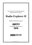
The 'SETUP' option page
The 'SETUP' option page (Figure 20) allows the user to customize the eTrex. This page
contains a list setup pages. In the context of the WHS survey we only need to deal with two
of them: the 'UNITS' and 'SYSTEM' ones (the 'DISPLAY' page corresponds to the same
page as the one described under section 3.2.3.1).
To access the desired setup you have to highlight its name in the list using the 'UP' or
'DOWN' buttons and press the 'ENTER' button.
Figure 20 - The 'SETUP' option page
19
09/25/02
GPS_field_guide
8:19 A9/P9
The 'UNITS' setup page
This page (Figure 21) allows the user to setup the units of the different parameters. It is
important to make sure that this page contains the setting specific to the WHS as
indicated in the Figure 21 a) and in the Quick Reference Guide.
b)
a)
Figure 21 - The 'UNITS' page (a) with the scroll down list (b)
To change the value or format in a specific field you have to first highlight it using the UP
or DOWN button (e.g. the position format field on the Figure 21). Press the ENTER
button to make the corresponding scroll down list appear from which you will select the
desired format or value (Figure 21). Press the ENTER button again in order to save the
change. The variance field cannot be change, this value is given by the GPS unit and
connected with the Earth's magnetic field variation.
Ones all the units have been setup it is possible to keep them as default be highlighting
the 'DEFAULTS' option and pressing the ENTER button
The 'SYSTEM' setup page
This page (Figure 22) allows the user to fix the operation mode (Normal, Battery Save,
Demonstration). It is recommended to put the device in the 'BATTERY SAVE' mode in
order to extend their life. It is also possible to set the receiver language. We recommend
using the receiver in English in order to follow the instruction reported on the different
documents provided. It may however be useful in certain case to change the language in
order to improve understanding of some options.
Changes can be done as in the other pages by highlightning the concerned field, pressing
the 'ENTER' button to make the scroll down list appear, selecting the desired language and
pressing the 'ENTER' button again to save the change.
Figure 22 - The 'SYTEM' page
20
09/25/02
GPS_field_guide
8:19 A9/P9
CHAPTER 4: TROUBLESHOOTING
4. 1 eTrex does not turn on:
1.
2.
3.
Check to see if the batteries are installed correctly and if the battery terminals are
clean.
If the eTrex does not turn on after point 1: place a fresh set of AA batteries in the
unit (refer to Quick Reference Guide point n°3 ' Installing the Batteries' and use
Alkalyne batteries as they have a longer life).
If eTrex still does not turn on, the problem requires the help of a technician (please
contact your supervisor).
4.2. The message "READY TO NAVIGATE"(Prêt à naviguer) does not
appear on the screen:
1. There may be large obstacles around you that stops the satellite signals; move to a
new location: a large, open area with a clear view of the sky.
2. Another window with a message may appear (see section 4.3 for the list of these
messages and their explanations).
4.3. The message "TROUBLE TRACKING SATELLITES. ARE YOU
INDOOR NOW?" appears on the screen.
1. You are indoor:
- Press the DOWN Button,
- Highlight 'YES', and press ENTER
- Go outdoor for the receiver to catch satellites signal (as the GPS unit
cannot receive the satellite signals when you are
indoors.)
2. You are not indoors and you are close to the open place where you turned the GPS
on (less than 800 km):
- Press the UP/DOWN buttons,
- Highlight 'NO'
- Press ENTER.
eTrex then asks:'HAVE YOU MOVED HUNDREDS OF
MILES/KM SINCE LAST USE?"
- Press UP/ DOWN buttons
- Highlight 'NO'.
- Press ENTER.
21
09/25/02
GPS_field_guide
8:19 A9/P9
- eTrex then asks: 'IS TODAY dd-mmm-yy?'. Two possibilities:
a) The date indicated matches the current date :
· Press UP/ DOWN buttons
· Highlight 'YES' and press the ENTER button, the
eTRex will continue tracking satellites and switch to
the Satellite page.
b) The date is incorrect:
· Press UP/ DOWN buttons
· Highlight 'NO' and press the ENTER button, the eTRex will do
an 'AUTOLOCATE' and switch to the Satellite page. (An
'AUTOLOCATE' forces the eTrex to search for any available
satellite to determine its location.)
3. You are not indoors but you are far from the place where you turned the eTrex on
(more than 800 km):
-Press the UP/DOWN buttons
- Highlight 'NO'.
- Press ENTER.
- eTrex then asks:'HAVE YOU MOVED HUNDREDS OF MILES/KM SINCE LAST
USE'?
- Press UP/DOWN buttons
- Highlight 'YES'.
- Press ENTER.
- eTrex will do an 'AUTOLOCATE' and switch to the Satellite Page.
4.4 I am not getting an accuracy higher (better) than 20 meters:
1. Wait 5 minutes on the same location
2. If the situation does not change after 5 minutes:
Move to a new location with a clear view of the sky. The best location would be
(in order of preference):
· The front door of the building/house (for building: try to see if it
is not possible to go on the roof)
· The side of the building/house
· A parking lot or a park close to the building/house
4.5 eTrex does not display the desired units when making the accuracy
or co-ordinates reading :
Check to make sure the eTrex is configured to use the Position Format, Datum and Units
desired. (Refer to the point 7 of the Quick Reference Guide: 'Units Setting')
22
09/25/02
GPS_field_guide
8:19 A9/P9
4.6 eTrex does not display the local time in the 'SETUP' page
The eTrex operates on universal time (or GMT, Greenwich Mean Time ).
It is not necessary to have your local time displayed. Do not worry about a wrong
displayed time.
4.7. The geographic coordinates I get are outside the range indicated in
the 'Country information' document :
1. Make sure the eTrex is configured as indicated in point 7 of the Quick Reference
Guide and redo the reading correctly.
2. If the eTrex is well configured, check that you have a clear view of the sky.
3. If this still does not work, move to a better place and take a new reading.
4. If the coordinates are still outside the range: change the batteries.
5. If all of that does not lead to a better result, contact your supervisor.
23
09/25/02
GPS_field_guide
8:19 A9/P9
GLOSSARY
Accuracy : How close to the real value a measurement is.
Backlight: Selectable on/off illumination that lights the display for enhanced screen at
night and in low light.
Contrast: The difference between the lightest and darkest areas on a display screen.
Coordinates : The unique description of a geographic position using numeric
characters.
Dilution of Precision (DOP): The dilution of precision (DOP) is an indication of the
quality of the results that can be expected from a GPS point position. It is a
measure based solely on the geometry of the satellites in the sky.
Ephemeris: The predictions of current satellite position that are transmitted to the
user in the data message.
Initialization: Refers to the procedure of telling a GPS receiver where it is, when it is
turned on for the first time. Information required for initialization includes
approximate present position in latitude/longitude coordinates, the current local
time and date (information obtained through the satellite signal when using the
eTrex unit).
Map Datums: Since the Earth is not flat a model needs to be used in order for the
GPS receiver to give the coordinates. These models are calls Datums.
Multipath: Mutipath is the phenomena by which the GPS signal is reflected by some
object or surface before being detected by the receptor antenna creating
multipath for a same signal that results in a calculation error when estimating
the distance between the satellite and the receiver
Position: A geographic location on the earth, commonly measured in latitude and
longitude.
Satellite constellation: The arrangement in space of a set of satellites.
Segment: One of several parts or pieces that fit with others to constitute a whole
object.
GPS Control segment: A Master Control Station and a number of monitoring
stations around the world that ensure the accuracy of satellite positions and their
clocks.
GPS Space segment: The network of 24 GPS satellites.
GPS User segment: The receivers of GPS signals such as your eTrex Unit.
24
09/25/02
GPS_field_guide
8:19 A9/P9
Variance: In this context correspond to the errors in magnetic compass readings
caused by variance in the earth's magnetic field at different locations on the
planet.
Waypoint: Current location on the face of the Earth, in terms of the specific
latitude/longitude coordinates.
BIBLIOGRAPHY / LINKS
This document has been created using information coming from the following
publications or Web Sites:
Garmin International, Inc. (2000): Garmin eTrex personal navigator, owner's manual.
MEASURE Evaluation (2001): Incorporing Geographic Information Into MEASURE
Surveys: A field Guide to GPS Data Collection.
Garmin Website: http://www.garmin.com
Garmin GPS Guide for beginners : http://www.garmin.com/manuals/gps4beg.pdf
Eagle GPS Tutorial: http://www.eaglegps.com/tutorial/gps/default.htm
Lowrance Electronics GPS Tutorial :
http://www.lowrance.com/Tutorials/GPS/gps_tutorial_01.asp
Mercator GPS Systems, The GPS Tutor: http://www.mercat.com/QUEST/gpstutor.htm
The Aerospace Corporation: http://www.aero.org/publications/GPSPRIMER/
Trimble GPS Tutorial and Glossary: http://www.trimble.com/gps/work.html
University of Colorado: http://www.colorado.edu/geography/gcraft/notes/gps/gps_f.html
Smithsonian National Air and Space Museum, Washington, GPS: A New Constellation
http://www.nasm.si.edu/galleries/gps/
25