1
TR-1
Autopilots
G L A D I ATO R
Owner’s Manual
1
906-2500-01
Rev H 1007
2
Safety
You are responsible for the safe and prudent operation
of your vessel. Your TR-1 Autopilot is a tool that will
enhance your capability to operate your boat and catch
fish. It does not relieve you from the responsibility for
safe operation of your vessel. You must avoid hazards to
navigation and never leave the helm unattended.
Before starting the hydraulic installation, please verify the type of hydraulic steering
in the boat. If it does not match the hydraulic layouts in this manual, please contact
technical support for specific installation procedures. Examples: Capilano,
Hynautic, Latham
NOTE:
Before proceeding with the installation and operation of the autopilot, read these instructions
thoroughly. TR-1 Autopilots cannot accept responsibility for installations where instructions
have not been followed, where substitute parts have been used, or where modifications have
been made to our products. For technical support please call, 1-866-559-0229.
1
Table of Contents
Chapter I User Guide
Introduction to operation and adjustments................................................................. 4
System functions and features ................................................................................... 4
Operating the system.................................................................................................. 5
Power On/Off (Deckmount Switch)........................................................................... 6
Illuminate keypad of the remote (Backlight)............................................................. 6
Engaging the autopilot in heading hold...................................................................... 6
Change heading with rudder function......................................................................... 6
Making a turn while in Autopilot............................................................................... 7
Shadow Drive............................................................................................................. 8
Warning Horn............................................................................................................. 8
Go to stored heading................................................................................................... 8
Reverse....................................................................................................................... 8
Selecting patterns....................................................................................................... 9
Change heading using Man Overboard.................................................................... 10
Change heading using Zigzags................................................................................. 11
Change heading using Step Turns............................................................................ 12
Change heading with circles.................................................................................... 13
Change heading with U-Turns................................................................................. 14
GPS Steering patterns............................................................................................. 15
Course over ground.................................................................................................. 16
Steer to waypoints.................................................................................................... 16
Orbit a waypoint....................................................................................................... 16
Cloverleaf pattern..................................................................................................... 17
Search pattern........................................................................................................... 18
How to change settings using the table of setup codes............................................ 19
Table of setup codes and the values of the parameters....................................... 20- 22
Chapter II Autopilot Setup
Dockside setup and sea trial setup of autopilot..................................................... 24-25
Compass calibration............................................................................................. 26-27
Autotune............................................................................................................... 27-29
Set North..................................................................................................................... 29
Trouble shooting guide............................................................................................. 30
Electrical layout........................................................................................................ 31
NMEA 0183 connections......................................................................................... 32
Non-compliant NMEA 0183 devices....................................................................... 33
Warranty Statement ................................................................................................ 34
2
Chapter I
........................
User Guide
3
Introduction to Operation and Adjustments
This section of this manual provides you with information of the TR-1 Gladiator autopilots’ capabilities.
We have made every effort to minimize the pain in getting you up to speed as a user of the TR-1, however,
programmable devices such as your TR-1, are often difficult to learn to use and to program. We recommend
that you do not take your fishing tackle on your first trip with your new autopilot. Take a few hours on a nice
day to get your system setup and familiarize yourself with its operation, then your first fishing trip with the unit
will really have you smiling.
This manual is laid out in sections that are, as best we can make them, self contained. We start with the features
and functions available and fundamentals of how the system works, then how to operate the basic functions, and
finally how to get into the fine adjustments.
System Functions and Features
The TR-1 is a heading hold autopilot. It steers to maintain a constant magnetic heading. The autopilot
measures magnetic heading with a fluxgate compass and receives rate of turn information from an angular rate
sensor (gyroscope). The autopilot computer forms a rudder rate command from a combination of the compass,
gyro, and engine tachometer signals. This rudder rate command is calculated and sent to the pump controller in
the electrohydraulic unit electronics 20 times each second. The pump controller servos the pumping speed and
direction to match the rudder rate command from the autopilot.
Beyond the basic heading hold function, the autopilot provides for several other modes of automatic and
manually controlled steering functions. These are listed below.
1. Rudder. Rudder steering is used for electrically steering without feedback from the gyro or compass. The
rudder moves while a turn button is held down, and stays in place when the button is let up. (Steering the boat
with the handheld without heading hold.)
2. Rudder command / Attitude hold (RCAH). (Steering the boat with the Handheld while in Autopilot)
RCAH is the primary means for changing the boats’ heading with the remote.
3. Man Overboard. See page10. The autopilot will execute a turn to the reciprocal course and pass near the
maneuver initiation point.
4. Zigzags. See page 11. The autopilot will steer a zigzag course with preset amplitude and period. Factory
Default is set an amplitude (turn) of 30 degrees, and the period (length) set at 1.5 minutes.
5. Step turns. See page 12. The autopilot will execute predetermined fixed angle turns in this mode. (Factory
Default is 15 degree turns)
6. Circles. See page 13. The autopilot will turn in continuous circles of preset lap time. (Factory Default is set
at a 5 minute circle.)
7. U-Turns. See page 14. The autopilot will execute a U-Turn by using the right or left chevron buttons on the
handheld
4
7. GPS steering.
7a. The autopilot will steer to a waypoint or series of waypoints.
7b. The autopilot will orbit a waypoint.
7c. The autopilot will steer a Cloverleaf pattern over a waypoint.
7d. The autopilot will steer a spiral search pattern around a waypoint.
7e. The autopilot will steer to constant course over ground.
8. Shadow Drive. The autopilot relinquishes control of the autopilot when the helm is turned and then
automatically takes over and steers when the boat is on a constant heading and there is no helm motion.
9. Reverse. The autopilot will attempt to execute many of the above steering functions while the boat is
backing.
10. Return to Selected Heading. The autopilot will drive the boat to a previously stored heading.
11. U-Turn. The autopilot will execute a U-Turn; to port or starboard, depending on which button is pressed.
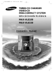
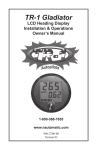
OPERATING THE SYSTEM
The autopilot is controlled with the handheld/remote, the helm and the deckmount switch. To make
things easy to talk about we will name the buttons as shown in the picture of the remote below.
Auto/Stby Button
Right Arrow Button
Left Arrow Button
Up Arrow Button
GPS Button
Down Arrow Button
Plus Button
Left Chevron Button
Right Chevron Button
Setup Button
Most of the buttons in the system have multiple functions, and many functions are executed by button push
sequences or by pushing more than one button at a time.
5
Power On/Off (Deckmount Switch)
Turn power on by pressing and releasing the [Deckmount] switch. Turn the power off by pressing and holding
the switch down until the [Deckmount] switch light has extinguished (about three seconds).
Power on is indicated by illumination of the [Deckmount] switch button and one or more
LED’s lit on the Hand Held.
Both the [Deckmount] button light and remote [STBY] LED will blink for about 30 seconds
after turning power on. During this 30-second time, the pilot computers are running self
test and starting up the compass and gyroscope. Autopilot steering is not available during this start up period.
While the system is in standby mode, the STBY LED will light solid on and the deckmount light will briefly
turn off once a second (occulting at 1 Hz).
Illuminate Keypad on Remote
To illuminate keypad on the remote for nighttime operation:
Press and hold [Setup] and press and release the [Up Arrow].
Repeat to turn the back light off. The down arrow will toggle the
brightness of the orange LED’s between bright and dim when the setup is held down.
Engaging the Autopilot In Heading Hold
The [Auto/Stby] button engages and disengages autopilot steering. The
[Deckmount] button performs the same function after the pilot is powered up.
When the button is pressed and released to go into Auto mode, the pilot captures the compass heading and
subsequently moves the rudder to hold that heading. The LED next to “Auto” will illuminate and the deckmount
light will be lit solid on. You should be steering your boat on a constant heading at the time you press the [Auto/
Stby] button.
Change Heading with Rudder Function
The rudder (steering) is directly controlled by [Right Arrow] and [Left Arrow] buttons
when the Rudder LED is illuminated. When you program the [Plus (+)] button for
Rudder, the system will toggle between Rudder mode and heading hold mode when you
press and release the [Plus (+)] button. (Autopilot or heading hold are not available
while you are in Rudder function.)
6
Making A Turn While In Autopilot
RCAH (Rudder Command Attitude Hold)
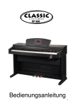
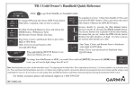
Change Heading with RCAH
You can steer to a new heading with the [Right Arrow] and [Left Arrow] buttons. See Fig. 1 .The pilot will
alter the heading by one degree per momentary press of either of these buttons. For example, pressing the
You can steer to a new heading with the Straight Right Arrow and Straight Left Arrow
[Left Arrow] button five times
will cause the heading to be changed by 5 degrees to the port. Holding either of
buttons. Momentary presses of either of these buttons will cause the pilot to alter the heading by
these buttons down causes the
to per
turnpress.
the rudder
so as topressing
make athe
port
or starboard
turn. button
The rudder
turns
onepilot
degree
For example,
Straight
Left Arrow
five times
will
as long as the button is heldcause
downtheorheading
until theto rudder
reaches
end of
its travel
range oreither
the boat
is turning
be changed
by 5the
degrees
to the
port. Holding
of these
buttons down
causes
therelease
pilot tothe
turnbutton,
the rudder
as to make
port orthe
starboard
Thethe
rudder
at it’s acceleration limit. When
you
the so
autopilot
willa move
rudderturn.
to stop
boatturns
fromas
long as the
is held
down orthe
until
the rudder
reaches
thethen
end moves
of its travel
range. When
turning. When the turn is stopped,
thebutton
autopilot
captures
compass
heading
and
the rudder
so as you
the button,
the autopilot
will move
thefirudder
stop the boat from turning. When the
to maintain this heading. Anrelease
example
of RCAH
turn is shown
in the
gure 2tobelow.
turn is stopped, the autopilot captures the compass heading and then moves the rudder so as to
maintain this heading. An example RCAH turn is shown in the figure below.
Heading when starboard
RCAH button released
Initial heading
Final heading
[Left Arrow]
[Right Arrow]
Starboard RCAH button released
Starboard RCAH button pressed
Boat path
Fig.2
Fig.1
7
22
Shadow Drive ™
When the Shadow Drive feature of the autopilot is enabled, the helm acts as an autopilot dis-engage switch. If
the autopilot is steering the boat, it will surrender control to the helm when the helm is moved. The autopilot
will automatically re-engage when the boat is on a constant heading and there is no helm movement.
Warning Horn
The System sounds a warning horn on the following events:
1. When the rudder is hard against a stop (Double Beep).
2. When the compass is suspect. This may happen when the boat rate of turn exceeds the gyroscope’s
measurement range. It is most likely to happen when the boat is making high speed turns in rough water. The
autopilot will not hold heading for several minutes after such an event (1 solid 3 second beep).
3. When the GPS sends a warning to the autopilot that the navigation data is not reliable. Press any key on the
remote to silence the horn (Continuous beep).
4. When GPS Navigation is terminated by Shadow Drive (1 Single Short Beep).
Go to Stored Heading
If you press and release the Down Arrow button while the autopilot is in heading hold
mode, the heading at the instant the button is pressed becomes the stored heading.
Subsequently, while you are in heading hold (at any heading), pressing and releasing
the Up Arrow button will cause the autopilot to steer to the stored heading.
Reverse
The autopilot will attempt to perform any of its steering functions when the boat
is backing in reverse gear. To engage the system in reverse:
1) Start from [Standby]
2) Press and hold the GPS [Rev] button
3) Press and release the [Auto/Standby] button
4) Release the GPS [Rev] button
8
buttons.
When you select special functions, by the methods described below, you are simply choosing
which function is to be executed by the pilot when you push one of the three special function
The Plus button is programmable to provide either MOB, ZigZags, or Rudder. The Left
buttons.
Chevron button is programmable to provide either Steps, Circles, or U Turns. The Right
Selecting
Patterns
Chevron
Orbiting,
Clover
Leaf, or The
Search
The Plusbutton
buttonisisprogrammable
programmabletotoprovide
provideWaypoint
either MOB,
ZigZags,
or Rudder.
Leftsteering
in
conjunction
with
your
GPS.
When
you
select
special
functions,
by
the
methods
described
below,
you
are
simply
choosing
Chevron button is programmable to provide either Steps, Circles, or U Turns. The Right which
function
is to
be executed
by the pilottowhen
youWaypoint
push one of
the threeClover
specialLeaf,
function
buttons
below.
Chevron
button
is programmable
provide
Orbiting,
or Search
steering
To
the functions
these programmable buttons, follow the directions below.
in change
conjunction
with yourofGPS.
The [Plus (+) ] button is programmable to provide either MOB, Zig Zags, or Rudder. The [Left
1.
must
in Heading
or Standby
Mode
process
can
start.Chevron]
Chevron]
isbe
programmable
to
provide
eitherbuttons,
Steps, before
Circles,
or U-Turns.
The
[Right
ToAutopilot
changebutton
the
functions
of theseHold
programmable
followselection
the
directions
below.
(AUTO
solid on orto STBY
solid on.
No other
LED's
button
is LED
programmable
provideLED
Waypoint
Orbiting,
Clover
Leaf,on.)
or Search Steering in conjunction
with
your GPS.must be in Heading Hold or Standby Mode before selection process can start.
1. Autopilot
theonSetup
button.
Three
next
to the
numbers
2.(AUTO
Press and
hold
LED
solid
or STBY
LED
solidLED's
on. No
other
LED's
on.) 1 through 9 will
To change the
functionswhich
of these
buttons,
follow the directions
below.
illuminate,
indicating
(3) programmable
special functions
are programmed
to operate.
For example, if
LED's
1, 4,and
andhold
7 illuminate,
system
is LED's
programmed
1) MOB1 when
the9 Plus
2. Press
the Setup your
button.
Three
next totothedo:numbers
through
will button is
1.illuminate,
Autopilot
mustTurns
be in to
Heading
Hold
or Left
Standby
Mode
before selection
process
start.
pressed.
2) Step
port (3)
when
the
Chevron
button
is pressed.
3) Stepcan
Turns
to(AutoifLED
indicating
which
special
functions
are programmed
to operate.
For
example,
solid
on 1,
orwhen
solid
on.your
No system
other
on.) 4) Orbit
starboard
Right
Chevron
buttonLED’s
pressed.
clockwise
when
the is
LED's
4,STBY
andthe
7LED
illuminate,
is programmed
to do:a waypoint
1) MOB when
the Plus
button
Right
Chevron
andthe
theLeft
system
is tracking
signal.3)5)Step
Orbit
a waypoint
pressed.
2) Stepbutton
Turns istopressed
port when
Chevron
buttona GPS
is pressed.
Turns
to
2.starboard
Press andwhen
holdthe
the
[Setup]
button.
Three
next
to
numbers
1 through
9 will when
illuminate,
counterclockwise
when
theChevron
Left
Chevron
button
is pressed
anda the
system
is tracking
a GPS
Right
buttonLED’s
is pressed.
4)the
Orbit
waypoint
clockwise
the
indicating
which (3)
special
functions
programmed
to do, thea GPS
factory
defaults
are: 1)aMOB
when
Right Chevron
button
is pressed
andarethe
system is tracking
signal.
5) Orbit
waypoint
signal.
the
[Plus (+)] buttonwhen
is pressed.
2) Step
Turnsbutton
to portiswhen
the and
[Leftthe
Chevron]
is pressed.
counterclockwise
the Left
Chevron
pressed
system isbutton
tracking
a GPS 3)
Step
Turnsthe
to Special
starboardFunction
when theyou
[Right
is pressed.
4) Orbit
waypoint
signal.
3.
Select
wantChevron]
to use by button
pressing
and releasing
theaPlus
and/orclockwise
when
the
[Right
Chevron]
button
is
pressed
and
the
system
is
tracking
a
GPS
signal.
Orbit a
Chevron buttons until the appropriate LED's are lit. See Special Function Indicators5)LED
waypoint
counterclockwise
when
the
[Left
Chevron]
button
is
pressed
and
the
system
is
tracking a
3.
Select
the
Special
Function
you
want
to
use
by
pressing
and
releasing
the
Plus
and/or
Numbers tables below.
GPS
signal.buttons until the appropriate LED's are lit. See Special Function Indicators LED
Chevron
below.
4.Numbers
Releasetables
the Setup
Button.
3. Select the Special Function you want to use by pressing and releasing the [Plus (+)] and/or Chevron
If you press and release the Down Arrow button while the autopilot is in heading hold mode,
buttons
until the
the appropriate
LED’s are lit. See Special Function Indicators LED Numbers tables
4. heading
Release
Button.
the
at theSetup
instant
the button is pressed becomes the stored heading. Subsequently, while
below.
If you
and release
theany
Down
Arrowpressing
button while
the autopilot
is in
heading
holdwill
mode,
you
are press
in heading
hold (at
heading),
and releasing
the Up
Arrow
button
cause
theautopilot
heading to
at the
button
is pressed becomes the stored heading. Subsequently, while
the
steerinstant
to thethe
stored
heading.
4.you
Release
[Setup]
button.
are inthe
heading
hold
(at any heading), pressing and releasing the Up Arrow button will cause
the
autopilot
to
steer
to
the
storedFunctions
heading. into start up defaults: Press and release the Setup
5. To make the selected Special
5. To make the selected Functions into startup defaults (save the changes into permanent memory):
the GPS
(Select
Load)
button, verify
button
(therelease
setup LED
should be
lit), then
press andLED
holdshould
Press
and
the [Setup]
button
(the [Setup]
be lit),
andand
thenrelease
press and
hold
5. To
make
the
selected
Special
Functions
into start
upDM
defaults:
Press
the Setup
that
the
Load
LED
is
lit,
and
then
press
and
release
the
button,
then
release
therelease
GPS
the
[Select
Load]
button.
Whilebeholding
down
the
[Select
Load]
the
the
GPSbutton,
(Selectpress
Load)and
button,
verify
button
(the
setup
LED
should
lit),
then
press
and
hold
(Select
Load)button button quickly, then release the GPS [Select Load] button.
[Deckmount]
that the LoadOn/Off
LED is lit, and then press and release the DM button, then release the GPS
(Select Load)button
SPECIAL FUNCTION
INDICATOR
NUMBERS
Pattern Indicator
LEDLED
Numbers
Following the directions
above,
you will be
able to access
all NUMBERS
of the Special Pattern Functions
SPECIAL
FUNCTION
INDICATOR
LED
listed below on your handheld.
Orbit
1
MOB
4
Steps
77
Orbits
21
MOB
ZigZag
54
Steps
Circles
7
88
3 LeafOrbit
Clover
Clover
Leaf
32
ZigZag
Rudder
65
UCircles
Turn
3 Leaf
Clover
Search
3
Rudder
6
U Turn
8
99
9
9
Search
Search
If you program the Bent Right Arrow and Bent Left Arrow buttons for Circles, pressing the
Bent Right Arrow button will cause your boat to be driven in a clockwise (from above) circle
with a lap time between 1 and 90 minutes (programmable). The Bent Left Arrow button will
cause counterclockwise turns. You can exit the circle and run straight anytime by pressing either
the Straight Right Arrow or Straight Left Arrow button.
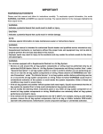
Change Heading Using Man Overboard
Step Turns
The Man Overboard (MOB) function causes the boat to turn to port until the reciprocal
course is established, with the goal of running alongside the point where the Plus button
If you program the Bent Right Arrow and Bent Left Arrow buttons for Steps, when one
was pushed, The boat path will be as shown in the figure below. The pilot will return to
of these buttons is pushed, the pilot will execute a port or starboard turn. The turn will
if either of
theangle
Right
Arrow, Left
or Plus
buttons are pressed.
terminateheading
when thehold
programmed
step
is reached.
TheArrow,
step angles
are programmable
from 1 to 90 degrees. Multiple pushes of these buttons will result in a turn through an angle
equal to the
sum14:
of The
the angles
per push. maneuver
For example,
have
the object
pilot for
Code
Man overboard
can ifbeyou
tuned
to programmed
run close to the
or 10
point
degree steps, five pushes of the Bent Right Arrow button will turn you 50 degrees to starboard.
at
any
given
speed,
but
may
miss
at
another
speed.
You
should
probably
adjust
the maneuver at a speed that is
180 degrees is the maximum turn sum.
below planing speed. If the object or point passes on your starboard reduce code 14.
You are responsible
as the captain
of your boat
to useMOB
the MOB feature in a manner as to not cause harm to any
Changing
Heading
With
person or property. Be aware of any objects in the water before pressing the MOB button. The MOB feature is
not set by GPS. Due to wind, waves and current your boat may not return to the exact reciprocal course when
The Man Overboard (MOB) function causes the boat to turn to starboard for a while then turn to
thereciprocal
MOB button
is pressed.
port until the
course
is established, with the goal of running alongside the point where
the MOB button was pushed. The boat path will be as shown in the figure below.
To change the settings for Man
Overboard:
1. Press and release the [Setup]
Button. The [Setup] LED will
illuminate to indicate the system
is ready to take setup commands
(button pushes).
3. Select and enter code 14 by
pressing and releasing the buttons
labeled 1 & 4 (14) until the
appropriate LED’s are lit. (See the
26
Code and Setup Choice on the table below.
4. Increase an adjustable parameter one step by each press of the [UP Arrow] button. When the parameter
is adjusted to its maximum value, the [Up Arrow] LED will light. The parameter is adjusted and is in use by
the autopilot immediately.
5. Decrease an adjustable parameter one step by each press of the [Down Arrow] button. When the
parameter is adjusted to its minimum value, the [Down Arrow] LED will light. The parameter is adjusted
and is in use by the autopilot immediately.
6. To save the changes into permanent memory and make the selected function into a startup
default: Press and release the [Setup] button (the [Setup] LED should be lit), and then
press and hold the [Select Load] button. While holding down the [Select Load] button,
press and release the [Deckmount] On/Off button quickly, then release the GPS [Select
Load] button.
Description
MOB Overshoot
Code
Range of Settings
Code 1 most overshoot command, 40 most under shoot command
14
Factory Setting
10
Code 14: The Man overboard maneuver can be tuned to run over or close to the object or point at any given
speed, but may miss at another speed. You should probably adjust the maneuver at a speed that is below
planing speed. If the object or point passes on your starboard reduce code 14.
10
is accomplished by pressing the Idle/Resume button. If the throttle is set
esume function will take the engine to idle. If the throttle is sitting in the
me function will return the throttle to the last "above idle" position. The
be programmed to perform Idle/Resume and not MOB or Zigzags.
Change Heading Using Zigzags
Change Heading with Zigzags
If you program the [Plus (+)] button for Zigzags (Fig 3) ,and you then press
the [Plus(+)] button the pilot will begin to zigzag about the heading you
Resume button for Zigzags (other), then when
youonpress
Idle/Resume
were
whentheyou
pressed the button. The zigzag angle and period are both
n to zigzag about the heading you were on when
you pressed An
the example
button. The
programmable.
zigzag path is shown in the figure below. When the
is doinginzigzags,
it will
return to heading hold if either the [Left Arrow],
re both programmable. An example zigzag system
path is shown
the figure
below.
Fig 3
[Right Arrow] or [Plus(+)] buttons are pressed.
Heading Hold
To engage Zigzags:
1) Press and hold the [Setup] button.
2) Press and light up the [number 2, Zigzag] LED on the handheld.
3) Release the [Setup] Button.
Boat Path
To start the zigzags, press and release the [Zigzag/Plus (+)] button on the
handheld, the autopilot will start the zig-zags.
Factory default sets the zig-zags at 30 degrees per zig-zag and the cycle
time is 3 minutes. If you wish to change those settings refer to the setup
codes below and refer to [Code 8] for the Amplitude (Degree of turn) 10
choices; 5 to 50 degrees by 5’s. [Code 9] The Zig-zag period (Length/Time)
has 20 choices from 1/2 to 10 minutes by 1/2’s.
To change the setup options for zigzags:
You must be in [Auto] or [STBY] mode before selection process can start
1. Press and release the [Setup] Button. The [Setup] LED will illuminate to
indicate the system is ready to take setup commands (button pushes).
2. Select the Setup Code you want to use by pressing and releasing the button labeled 8 or 9 until the
appropriate LED is lit. (See the Codes and Setup Choices on the table below.
27
3. Increase an adjustable parameter one step by each press of the [UP Arrow] button. When the parameter is
adjusted to its maximum value, the [Up Arrow] LED will light. The parameter is adjusted and is in use by the
autopilot immediately.
4. Decrease an adjustable parameter one step by each press of the [Down Arrow] button. When the
parameter is adjusted to its minimum value, the [Down Arrow] LED will light. The parameter is adjusted and
is in use by the autopilot immediately.
5. To save the changes into permanent memory and make the selected function into a
startup default: Press and release the [Setup] button (the [Setup] LED should be lit),
and then press and hold the [Select Load] button. While holding down the [Select Load]
button, press and release the [Deckmount] On/Off button quickly, then release the GPS
[Select Load] button.
Description
Zigzag Amplitude (Degree of turn)
Zigzag Period (Length)
Code
Setup Options (Parameters)
8 10 choices/ 5 to 50 Degrees by 5’s
9
20 choices 1/2 to 10 minutes by 1/2’s
11
Factory Settings
30 degrees
1.5 minutes
Change Heading Using Step Turns
If you program the [Right Chevron] and [Left Chevron[ buttons for Step turns, when one of these buttons is
pushed, the pilot will execute a port or starboard turn. The turn will terminate when the programmed step angle
is reached. The step angles are programmable from 1 to 90 degrees. Multiple pushes of these buttons will
result in a turn through an angle equal to the sum of the angles per push. For example, if you have programmed
the pilot for 10 degree steps, five pushes of the [Right Chevron] button will turn you 50 degrees to starboard.
180 degrees is the maximum turn sum.
To use Step Turns:
1) Press and hold the [Setup] button.
2) Select and light up [number 4] [Step] LED on the handheld.
3) Release the [Setup] button.
4) When you are ready to initiate Step Turns, do so by pressing either the
[Right Chevron] or [Left Chevron] Button. Factory default has these set
for a 15 degree turn.
To change the setup options for Step Turns:
You must be in [Auto] or [STBY] mode before selection process can start
1. Press and release the [Setup] Button. The [Setup] LED will illuminate to indicate the system is ready to
take setup commands (button pushes).
2. Select the Setup Code you want to use by pressing and releasing the button labeled 6 until the appropriate
LED is lit. (See the Codes and Setup Choices on the table below).
3. Increase an adjustable parameter one step by each press of the [UP Arrow] button. When the parameter
is adjusted to its maximum value, the [Up Arrow] LED will light. The parameter is adjusted and is in use by
the autopilot immediately.
4. Decrease an adjustable parameter one step by each press of the [Down Arrow] button. When the
parameter is adjusted to its minimum value, the [Down Arrow] LED will light. The parameter is adjusted
and is in use by the autopilot immediately.
5. To save the changes into permanent memory and make the selected function into a startup
default: Press and release the [Setup] button (the [Setup] LED should be lit), and then
press and hold the [Select Load] button. While holding down the [Select Load] button,
press and release the [Deckmount] On/Off button quickly, then release the GPS [Select
Load] button.
Description
Code
Step Turns (Degrees per Step)
6
Setup Options (Parameters)
10 choices/ 1, 2, 3, 4, 5, 10, 15, 30, 45, or 90
Degrees
12
Factory Setting
15 degree
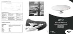
Change Heading with Circles
If you program the [Right Chevron] and [Left Chevron] buttons for Circles, pressing the [Right Chevron] button
will cause your boat to be driven in a clockwise (see figure below) circle with a lap time between 1 and 90 minutes
(programmable). The [Left Chevron] button will cause counterclockwise turns. You can exit the circle and return
to heading hold anytime by pressing either the [Right Arrow] or [Left Arrow] button.
Circles: 1) Press and hold the [Setup] button. 2) Select and light up [number
5] [Circle] on the handheld. 3) Release [Setup] button. 4) When you are
ready to start your circles press the [Chevron arrow buttons] in the direction
you would like to start your turn. Example: To start your turns in a clockwise
rotation, press the [Right Chevron Arrow] button. Factory default has the
circles set at a 5 minute circle time. If you would like to change those settings, refer to [Code 7] in the table of
setup codes (Below).
Right Chevron
Button Pressed Here
Left Chevron
Button
Pressed
Here
Clockwise Rotation
Counterclockwise Rotation
To change the setup options for Circles:
You must be in [Auto] or [STBY] mode before selection process can start
1. Press and release the [Setup] Button. The [Setup] LED will illuminate to indicate the system is ready to take
setup commands (button pushes).
2. Select the Setup Code you want to use by pressing and releasing the button labeled 7 until the appropriate
LED is lit. (See the Code and Setup Choices on the table below).
3. Increase an adjustable parameter one step by each press of the [UP Arrow] button. When the parameter is
adjusted to its maximum value, the [Up Arrow] LED will light. The parameter is adjusted and is in use by the
autopilot immediately.
4. Decrease an adjustable parameter one step by each press of the [Down Arrow] button. When the parameter
is adjusted to its minimum value, the [Down Arrow] LED will light. The parameter is adjusted and is in use by
the autopilot immediately.
5. To save the changes into permanent memory and make the selected function into a startup
default: Press and release the [Setup] button (the [Setup] LED should be lit), and then
press and hold the [Select Load] button. While holding down the [Select Load] button,
press and release the [Deckmount] On/Off button quickly, then release the GPS [Select
Load] button.
Description
Circle Time
Code
7
Setup Choices (Parameters)
Factory
Setting
10 choices/ 1, 2, 3, 4, 5, 10, 15, 30, 45, or 90 Minutes
5
13
Change Heading with U-Turn
If you program the [Right Chevron] and [Left Chevron] buttons for U-Turns, pressing the [Right Chevron]
button will cause the boat to make a U Turn to the starboard, and the [Left
Chevron] button will cause the boat to make a U Turn to port. You can exit
the U-Turn and return to heading hold anytime by pressing either the [Right
Arrow] or [Left Arrow] button.
To Program a U-Turn:
You must be in [Auto] or [STBY] mode before selection process can start
1. Press and hold [Setup] button.
2. While holding down the [Setup] button, select and light up [number 6 LED] [U-Turn] on the handheld.
(press and release button until the 6 LED is lit.)
3. Release the [Setup] button.
4. When you are ready to initiate a U-turn press the right or left Chevron buttons, depending on the direction
you want to make the U-turn. Example: To make a U-turn to starboard, press and release the [Right Chevron
button]. If you want this button to be a startup default, you will need to download the settings into permanent
memory, otherwise it will go back to factory defaults when the system is turned off and restarted.
5. To save the changes into permanent memory and make the selected function into a startup
default: Press and release the [Setup] button (the [Setup] LED should be lit), and then
press and hold the [Select Load] button. While holding down the [Select Load] button,
press and release the [Deckmount] On/Off button quickly, then release the GPS [Select
Load] button.
Press the
Left
Chevron Button
to U-Turn to Port
Press the Right
Chevron Button
to U-Turn to
Starboard
14
GPS Steering Patterns
The GPS steering functions are not guaranteed to work with all GPS systems. Each
manufacturer of GPS equipment puts his own spin on how to assemble the data on the
NMEA data bus. Sometimes the data on the bus will not conform to the needs of the
autopilot. The autopilot expects to see, at least, the NMEA data sentences $GPRMB and
$GPRMC at 4800 baud. These sentences are the minimum recommended data to be
transmitted when there is an active way point. Some GPS systems do not conform to this
NMEA specification.
Almost all GPS systems truncate the crosstrack error data to 0.01 NM resolution, this
means that the autopilot cannot be expected to stay on track any closer than 60 to 120 feet
from the course line.
There is a large discrepancy between manufacturers in how they warn the user when the
navigation fix is compromised. Some systems alert the NMEA bus listener immediately
upon position fix loss but wait 30 seconds to a minute to warn the operator on the GPS
display. This is disconcerting to the user because his autopilot drops out (The autopilot
stops using the GPS steering command immediately upon receiving a warning from the
navigator.) of GPS steering and there is often no indication on the GPS display that
anything is wrong with the GPS. Some manufacturers wait a 30 seconds to alert the user
via the display and the devices on the NMEA data bus when the position fix is broken.
The worst performance in all the GPS units we have tested occurs when a satellite is
occluded by the horizon; we have seen steering errors on the order of several hundred
feet in these situations.
The autopilot cannot fix steering errors that are GPS generated. Keep an eye on where
you are going when you couple the GPS to the autopilot.
When the autopilot is taking steering commands from the GPS, the GPS LED will be lit
solid. If the autopilot detects a GPS problem it will blink this LED and sound the
warning horn. Press any button to extinguish the blinking LED, and cancel the warning
horn.
North must be set in order for any of the GPS fishing patterns to work correctly. It also needs to be done
if any GPS steering or radar overlay functions are going to be used.
Verify NMEA Connections: Verify that the NMEA connections for the GPS are functioning. Turn on the GPS. With
the Autopilot in [Standby], press and release [Setup] button on the handheld. Press and light up the number 4 and the
number 8 LED’s [Code 48]. If the [up arrow] LED lights when you hold down the [GPS]/ [Select Load] button, the
autopilot does not acknowledge the validity of the GPS data.
To set North:
To run a GPS course requires that the autopilot compass is in agreement with the GPS’s magnetic map. You need to set
North with the pilot in standby mode.
If you have a GPS connected to the autopilot and $GPRMC is valid and correctly formatted > Set North by running in
STBY with code 48 selected, run your boat at planning speed, at any constant heading - press and hold the GPS [Select
Load] button, and then press and release the [Deckmount]. Your pilot will power down after North is set.
15
Course Over Ground
If you press and release the GPS button when the autopilot is in heading hold and the
GPS does not have an active route, the pilot will maintain the GPS course over ground
instead of the magnetic heading. Be aware that the course over ground calculated by
the GPS is erratic at low speeds.
All the special function and turn buttons will continue to behave as if you are in normal
heading hold. If you use any of the normal turning buttons, course over ground hold is
terminated.
Steer to Waypoint(s)
If you press and release the [GPS button] when the autopilot is in heading hold and
the GPS has an active route, the pilot will steer to the selected waypoint.
If you are more than 1,000 ft off the course line, the pilot will steer directly at the
waypoint and not try to remove crosstrack error.
Cancel GPS navigation and return to heading hold by pressing the [Right Arrow] or
[Left Arrow] button
Orbit a Waypoint
The autopilot will orbit
the waypoint you have
active in your GPS, with
the waypoint to your
starboard side if you
press the [Right Chevron] button when the GPS LED is
Lit and the special function Orbit has been enabled. The
waypoint will be on your port side if you use the [Left
Chevron] button.
To enable Orbits: Press and hold [Setup] button on
handheld, press and select [Orbits] (number 7 LED on
handheld).
The orbital radius is approximately the distance from
the waypoint at the time you press one of the Chevron
buttons.
Return to heading hold by pressing the [Right Arrow] or
[Left Arrow] button.
16
Distance from waypoint at the time
you press the Chevron buttons.
[Right Chevron]
Button Pressed
Waypoint in GPS
[Left Chevron]
Button Pressed
Clover Leaf Pattern
The clover leaf pattern is intended for use when you wish to repeatedly
pass over a point where you think fish may be holding.
Waypoint
Selected on GPS
You will need to setup
the special nav function
buttons (above) for
search patterns.
1. Press and hold [Setup] button on handheld.
2. While holding down the [Setup] button, select and light
up [number 8] LED [Clover] on the handheld. (You will
press the button twice.) Release the Setup button.
Right Chevron
Button Pressed
Left Chevron
Button Pressed
3. You must mark the location of the clover leaf stem
with a waypoint in your GPS. Once the waypoint is saved,
select “go to” this waypoint on your GPS.
4. From heading hold, press and release the [GPS button]
on the handheld. The pilot will start maneuvering toward
the waypoint.
Figure 4
If you have selected Clover Leaf pattern as the special function for the Chevron buttons, pressing either
Chevron button will start the boat on the clover leaf pattern. If you used the Right Chevron button the clover
leaf will be traversed by always turning to starboard, the Left Chevron button will cause the pattern to be
traversed while always turning to port. (See Figure 4) The length of one of the clover leaves is programmed
with setup code 28. It is adjustable in length from 500 ft to 6,000 feet in 100 ft. increments. See table below.
To change the setup options for Clover Leaf:
You must be in [Auto] or [STBY] mode before selection process can start
1. Press and release the [Setup] Button. The [Setup] LED will illuminate to indicate the system is ready to
take setup commands (button pushes).
2. Select the Setup Code you want to use by pressing and releasing the button labeled 2 & 8 until the
appropriate LED is lit. (See the Code and Setup Choices on the table below).
3. Increase an adjustable parameter one step by each press of the [UP Arrow] button. When the parameter is
adjusted to its maximum value, the [Up Arrow] LED will light. The parameter is adjusted and is in use by the
autopilot immediately.
4. Decrease an adjustable parameter one step by each press of the [Down Arrow] button. When the
parameter is adjusted to its minimum value, the [Down Arrow] LED will light. The parameter is adjusted and
is in use by the autopilot immediately.
5. To save the changes into permanent memory and make the selected function into a
startup default: Press and release the [Setup] button (the [Setup] LED should be lit),
and then press and hold the [Select Load] button. While holding down the [Select Load]
button, press and release the [Deckmount] On/Off button quickly, then release the GPS
[Select Load] button.
Description
Clover Leaf Length
Code
28
Setup Options (Parameters)
500 to 6,000 ft by 100ft. Increments
17
Factory Setting
1,000
To do an outward spiraling search from a waypoint, setup the special function buttons for sear
patterns. (See page 28 Selecting Special Functions) When you are near the waypoint you wan
to search from, select go to this waypoint on your GPS. With the pilot in heading hold, pres
and release the GPS (Select Load) button and then press and release one of the Bent Arrow
buttons. If you pressed the Bent Right Arrow button, the waypoint will remain on your
starboard side as the spiral search unwinds. The spacing between the spiral laps is set with set
code 249.
Search Pattern
Return to heading hold by pressing one of the straight arrow buttons. An example of the sea
pattern is shown in the figure below.
To do an outward spiraling search from the waypoint, setup the
special nav function
buttons for search
patterns.
1. Press and hold the [Setup] button on the handheld.
2. Press and light up the [number 9] LED on the handheld.
Release the [Setup] Button.
3. When you are near the waypoint you want to search
from, select “go to” this waypoint on your GPS.
4. With the pilot in heading hold, press and release the [GPS
button] on the handheld, and then press and release one of
the Chevron Buttons. If you pressed the [Right Chevron]
button, the waypoint will remain on your starboard side as
the spiral search unwinds.
To change the setup options for Search Pattern:
You must be in [Auto] or [STBY] mode before selection process can start
1. Press and release the [Setup] Button. The [Setup] LED will illuminate to indicate the system is
ready to take setup commands (button pushes).
2. Select the Setup Code you want to use by pressing and releasing the buttons labeled 2 &5 until the
appropriate LEDs are lit. (See the Code and Setup Choices on the table below)
3. Increase an adjustable parameter one step by each press of the [UP Arrow] button. When the
parameter is adjusted to its maximum value, the [Up Arrow] LED will light. The parameter is
adjusted and is in use by the autopilot immediately.
4. Decrease an adjustable parameter one step by each press of the [Down Arrow] button. When the
parameter is adjusted to its minimum value, the [Down Arrow] LED will light. The parameter is
adjusted and is in use by the autopilot immediately.
5. To save the changes into permanent memory and make the selected function into a
startup default: Press and release the [Setup] button (the [Setup] LED should be lit),
and then press and hold the [Select Load] button. While holding down the [Select Load]
button, press and release the [Deckmount] On/Off button quickly, then release the GPS
[Select Load] button.
Description
Search Spacing
Code
25
Setup Options (Parameters)
50 to 1,000 ft, by 50 ft. increments
18
Factory Setting
50
How to Change Settings Using The Table of Setup Codes
1. Autopilot must be in heading hold [Auto],[Standby], or [ GPS Track] mode before selection
process can start. ( [Auto] LED solid on or [STBY] LED on solid or [GPS Track] LED solid
on.)
2. Press and release the [Setup] Button. The [Setup] LED will illuminate to indicate the
system is ready to take setup commands (button pushes).
3. Select the Setup Function you want to use by pressing and releasing the buttons labeled 1
through 9 until the appropriate LED’s are lit. (See the Table of Setup Codes and values changes
on the following pages)
4. Increase an adjustable parameter one step by each press of the [UP Arrow] button. When
the parameter is adjusted to its maximum value, the [Up Arrow] LED will light. The parameter
is adjusted and is in use by the autopilot immediately.
5. Decrease an adjustable parameter one step by each press of the [Down Arrow] button.
When the parameter is adjusted to its minimum value, the [Down Arrow] LED will light. The
parameter is adjusted and is in use by the autopilot immediately.
6. You can stay in [Setup] and adjust more than one parameter.
7. Compass Calibration, and autotune are setup conditions that take the system over. You
can get out of compass calibration by turning the power off and can back out of autotune by
pressing any button on the remote. Setting compass North will cause the autopilot to turn off
after the compass realigns. The button sequences for their operation are given in the table of
Setup Codes on the following pages.
8. To view the operating value of an adjustable parameter, enter its code per the Table of Setup
Codes, then press and hold the [Select Load] GPS button. The LED on the [Up Arrow] button
will blink the number of tens the parameter is set to and the LED on the [Down Arrow] button
will blink the number of ones the parameter is set to. For example, if the parameter is set to
a current value of 15, the [Up Arrow] LED will blink once and the [Down Arrow] LED will
blink 5 times to indicate the parameter is set to 1 (blink) X 10 + 5 (blinks) X 1. Of course,
when a parameter is adjusted to its minimum or maximum value, the appropriate LED stays on
solid per steps 4. and 5. above. Note: The number of blinks, like 15 in the example, tells you
how many steps up from the minimum setting.
9. For temporary use of the adjusted parameters: Press and release the [Setup] button to exit
the setup mode.
10. To make the selected Functions into startup defaults (save the changes into permanent
memory): Press and release the [Setup] button (the [Setup] LED should be lit), and then
press and hold the [Select Load] button. While holding down the [Select Load] button,
press and release the [Deckmount] On/Off button quickly, then release the GPS [Select
Load] button.
19
Table of Setup Codes and Values of the Parameters
SPECIAL FUNCTIONS SETUP CODES
Description
Code
Values of the Parameters
Step Turns (Degrees per Step)
6
Circle Time
Zig-Zag Amplitude (Degree of turn)
7
8
10 choices/ 1, 2, 3, 4, 5, 10, 15, 30, 45, or 90
Degrees
10 choices/ 1, 2, 3, 4, 5, 10, 15, 30, 45, or 90 Minutes
10 choices/ 5 to 50 Degrees by 5’s
Zig-Zag Period (Length)
MOB Overshoot
9
14
20 choices 1/2 to 10 minutes by 1/2’s
1 most overshoot command, 40 most under shoot command
Factory
Defaults
15
5
30
1.5
10
Code 14: The Man overboard maneuver can be tuned to run over or close to the object or point at any given speed, but may miss
at another speed. You should probably adjust the maneuver at a speed that is below planing speed. If the object or point passes on
your starboard reduce code 28. See page 15.
Clover Leaf Length
28
500 to 6,000 ft by 100ft. Increments
1,000
NAVIGATION FUNCTION CODES
Description
Code
Values of the Parameters
Factory
Defaults
Navigation Gain
15
1 lowest gain, 73 highest gain
50
Navigation Trim Gain
16
1 lowest gain, 73 highest gain
49
Code 15 & 16: Most GPS systems only send cross track error across the NMEA 0183 data bus with .01 mile (60 feet) resolution.
Unfortunately, they display cross track error to the nearest foot. What this means is, don’t expect the autopilot to zero the cross
track error because the information it has is-that any crosstrack error less than 60 ft (as seen on the GPS display) is zero feet. Adjust
parameter 15 up until the boat oscillates back and forth near the course line, then back it down a few clicks. Increase parameter 16
until you can see that standoff from the course line decreases over time.
Use Magnetic North
Set North
17
48
[Up Arrow] for Mag [Down Arrow] for True Heading
MAG
In [Standby] Press and hold GPS [Select Load]- if Up Arrow
LED lights, point boat north-then press and release DM
Use Synthetic XTE
167 [Up Arrow] for on, [Down Arrow] for off
On
Code 167: On some GPS’ this code may result in tighter tracking near waypoints.
Use NMEA Checksum
347 [Up Arrow] for on, [Down Arrow] for off
On
Code 347: If your GPS calculates checksums wrong, you may still be able to use it with this code turned off. Data
integrity is compromised in this condition.
Use Reversed XTE
18
[Up Arrow] for on, [Down Arrow] for off
Off
Code 18: Some GPS’ send the wrong direction to steer with the crosstrack error signal. Use this code to fix this
problem.
Use GPS 1 GPS 2
34
[Up Arrow] for 2, [Down Arrow] for 1
1
Code 34: This code switches between the two sources of NMEA navigation data used by the autopilot to steer with.
Update rate for HDG out
49
0 (off) to 10 HZ Update Rate
10 HZ
Code 49: With this code at the bottom of its range (Down Arrow LED on) the autopilot does not transmit $APHDG. With
any settings other than off, the data is transmitted at a rate equal to (1-code 49 setting) HZ. up to a maximum rate of 10 Hz.
Fine Heading Adjust
168 [Up Arrow] increase heading out .1 deg. [Down Arrow] decreases heading
out .1 deg. Note: Very Slow response to buttons.
20
Table of Setup Codes
FINE TUNING CODES
Description
Code
Values of the Parameters
Factory
Defaults
39
Acceleration Limiter
5
1 lowest accel, 100 Highest accel
Code 5: This parameter limits the aggressiveness of the autopilot controlled turns. Turn it up to allow higher rate turns
and down to limit the turn rate.
Seastate Filtering
1
1 least responsive steering, 4 most responsive
steering
4
Code 1: Seastate adjustments, toward least responsive, slow the heading response down and reduce rudder activity. Most of the
time you will want to run with this parameter all the way at the top of its range. In choppy or trailing seas at low speeds, reducing
this parameter will save wear and tear on your system.
Low Speed Rudder Gain
27 1 lowest gain 97 highest gain
39
Low Speed Counter Rudder Gain
37 1 lowest gain, 97 highest gain
72
High Speed Rudder Gain
29 1 lowest gain 97 highest
39
High Speed Counter Rudder Gain
39 1 lowest gain, 97 highest gain
72
Following Seas Switch
159 [Up Arrow] on, [Down Arrow] off
off
Code 159: Turning this parameter on may increase stability in severe trailing seas.
Turn Stop Adjust
268 1 least adjustment, 40 most adjustment
1
Code 268: At planing speed and for large turn angles; if your boat tends to turn further than you programmed for, (like
50 degrees when you programmed 45 degrees) and then slowly recovers to the turn angle you expected, turning this
parameter up may solve the problem.
AUTOMATED SETUP CODES
Description
Calibrate Compass
Autotune
Code
47 Hold Down [Select Load] Button, Press and Release Deckmount Button
to Start Calibration Process
58 Hold Down [Select Load] Button, Press and Release Deckmount Button
to Start Tuning Process.
Code 57: Code 57 lets you select an alternate autotune. You may want to try this
if the normal tune didn’t work. After selecting the alternate by selecting code 57 and
pressing the Down Arrow button (so that the Down Arrow LED is lit), go back to code
58 to initiate the autotuner.
Load Factory Compass
247
Load Factory Pilot
248
Show Software Version
369
Hold down [Select Load] button, Press and Release Deckmount Button
to Reload Factory Pilot Settings
Hold Down [Select Load] Button, press and release Deckmount Button
to Reload Factory Pilot Settings
Hold Down [Select Load] Button, version=blink code/100
21
Table of Setup Codes
TACHOMETER CODES
Description
Code
RPM Source Configuration
Values of the Parameters
259
1, none/ 2, Port/ 3, Starboard/ 4, Both
267
1 to 255 by 1’s
Factory
Defaults
2
Code 259: For single engine installations, set this code to 2 (1 blink) (and hook the blue and black wires up to your
engine tach leads).
Pulses per Revolution
6
Code 267: The number of tach pulses per engine revolution is an engine specific parameter. The following settings are
a good starting point, however you need to verify them on operation. V8 engines 4 ppr (3 blinks) Most outboards 6ppr
Show Port RPM
35
Hold Down [Select Load] button: 1000’s blink on
Up Arrow 100’s blink on Down Arrow
Show Starboard RPM
36
Same As Above
Transition RPM
348
100 to 6000 by 100’s
3000
Code 348: Set this code to the RPM’s that your boat runs when almost on plane.
Low RPM Limit
357
100 to 6000 by 100’s
500
Code 357: If your autopilot runs well at all RPMs but is a little too active at idle, you can increase this low
limit RPM to a setting that is higher than your idle RPM to reduce autopilot rudder activity at idle.
High RPM Limit
359
100 to 6000 by 100’s
6000
Code 359: If your autopilot runs well at all RPM’s but you would like a little stiffer heading hold at the top end,
reducing this setting to an RPM lower than your actual peak RPM will help
HYDRAULIC CODES
Description
Code
Values of the Parameters
Helm Displacement
269
.1 to 6 by .1’s
Pump Displacement
169
[Up Arrow] for 4 liter, [Down Arrow] for 2 liter
Turns Lock to Lock
26
.1 to 10 by .1’s
Sloppy Linkage Compensation
257
8 settings, 8 for most sloppy
Factory
Defaults
1.7
2 liter
4.5
1
Code 257: In case of sloppy and loose steering linkages, increasing this parameter may help to reduce heading
oscillations due to the linkage. Use with caution.
Shadow Drive Desensitize
368
1 most sensitive, 40 least sensitive
20
Code 368: If the shadow drive is being false tripped, i.e., autopilot is disconnected when the helm is held
still, increasing this parameter may help. False tripping is usually due to leakage of fluid past the helm pump
lock valve. You may need to repair the helm valves if you cannot eliminate false trips.
Shadow Drive Enable
367 [Up Arrow] for On, [Down Arrow] for Off
on
Reversed Hoses
249
[Up Arrow] for Reversed, [Down Arrow] for Normal
Norm
Code 249: In case of hoses installed backwards, use this code to electronically reverse the steering direction.
22
Chapter II
................
Autopilot Setup
23
Dockside Setup and Sea Trial Setup of Autopilot
Your autopilot needs to be setup and tuned to your boat dynamics and motor configuration.
It is important to get the autopilot operating the best in can. The Dockside Setup and the
Sea Trial Setup are steps that must be followed to achieve the best performance from the
TR-1 Gladiator Autopilot. Have patience and try to do the Sea Trial Setup on a nice calm
day. Follow the directions below. These steps are in a sequence to help keep you from
making any errors. If you have any questions, please call us at 1-866-559-0229.
1. Turn autopilot system on. Press the deckmount (on/off switch) on, the deckmount will
blink slowly for 30 seconds during startup. The system will automatically go into standby
mode, and the deckmount will then blink rapidly. No functions are available during
startup. You will be using the handheld and deckmount switch to enter codes, change, and
save the values of the parameters. Parameters and their values are on the Table of Setup
Codes, (Pages 25-27)
2. Lock to Lock times. Count the number of turns it takes your helm to go from lock to
lock and adjust the parameter of code 26 to match. (Factory default is set at 4.5) The value
of code 26 can be seen in the blink code flashed on the up and down arrow buttons on the
handheld. Press and light up the [Setup] LED , press and light up numbers 2 & 6, [Code
26]. Press and hold the [Select Load] (GPS) button. The number of turns is 1/10th of the
blinked code + 1. Example: if the blinked code is 44 (The up arrow will blink 4 and the
down arrow will blink 4) the number of turns is (44 + 1)/10 = 4.5 turns lock to lock.
3. Helm displacement. The value of [Code 269] should be set to reflect the helm
displacement. (Factory Default is set at 1.7). Press and release [Setup] button. Press and
light up [Code 269] on the handheld. By pressing and holding down the [Select Load]
(GPS) button on the handheld, the up and down arrows will blink to reflect the helm
displacement code. The helm displacement is usually written on the body of the helm
pump. Example: The blinked code for a 1.7 cu in/rev helm would be 16, (the up arrow
blinks once and the down arrow blinks 6) since (16 +1)/10 = 1.7.
4. Verify the direction of steering is correct. Turn the autopilot on and switch from
standby to autopilot. When the right straight arrow turn button is pressed on the handheld
remote, the motor should turn the boat to the right. When the left straight arrow turn
button is pressed on the handheld/remote, the motor should turn the boat to the left. If this
is incorrect use [Code 249] for reversed hoses. Press and release, and light up the [Setup]
LED, press and light up [Code 249] on handheld, if the down arrow is lit, press the up
arrow to reverse hoses. If you change this setting, download changes into permanent
memory by following step 8.
24
Dockside Setup: Steps 1-9 can be done at the dock before heading for open water.
5. RPM Source Configuration. The default setting on the autopilot is set for a Single
Engine. If you have twin engines or more, you will need to change [Code 259] to match
your motor configuration. Twin engines; Press, release and light up the [Setup] LED on
the handheld, press and enter [Code 259] on the handheld. Press the [Up Arrow] TWO
(2) times which is setting the parameter to [(4) Both]. See page 22 code 259 for more
information.
6. Verify the autopilot tachometer (Tach Sensor Cable) is functioning properly. With
the engine(s) running. Press, release and light up the [Setup] LED on the handheld, and
press and light up [code 35]. Press and hold the [Select Load] GPS button and you
should see the [Up Arrow] and [Down Arrow] LED’s blink your port engine’s RPM. For
example, when the [Up Arrow] LED blinks 2 times and the [Down Arrow] LED blinks
5 times your engine is running at 2500 RPM. [Code 36] works the same way as code 35
for the starboard engine instead of the port engine. The autopilot tachometer system has a
lower limit setting of 200 RPM. If needed, adjusting [Code 267] (pulses per rev) to make
your autopilot tachometer match the tach on your dashboard.
7. Transition RPM. This is the RPM at which your boat transitions from displacement
to planing speed. [Code 348] is set to a factory default of 3000 (2 blinks of the [Up
Arrow] LED and 9 blinks of the [Down Arrow] LED +1). You should set it to your
boat’s transition RPM. (Example: Say that your planing speed is at 2500 RPM’s; With
the [Setup] LED lit, press and light [code 348], since the factory default is 3000 which is
2 blinks of the up arrow and 9 blinks of the down arrow (The value can be seen with the
[Setup] LED lit, press and hold the [Select Load] GPS , release the select load button, then
click the down arrow 5 times; that will set your transition RPM’s at 2500.) If you don’t
know what the transition RPM is, you will need to do this as part of your Sea Trial Setup.
8. Download to permanent memory the parameters you have adjusted so far. (This
must be done) With the [Setup] LED lit, press and hold the GPS [Select Load] button
- the [load] LED should illuminate on the handheld, while still holding down the [Select
Load] button, press and release the [Deckmount], on/off button quickly, then release the
[Select Load] GPS button.
9. Verify NMEA Connections: Verify that the NMEA connections for the GPS are
functioning. Turn on the GPS. With the Autopilot in [Standby], press and release
[Setup] button on the handheld. Press and light up the number 4 and the number 8
LED’s[ Code 48]. If the [up arrow] LED lights when you hold down the [Select Load]
(GPS) button, the autopilot does not acknowledge the validity of the GPS data.
25
Sea Trial Setup: Steps 10-15 will need to be performed on open water, free of obstacles.
10. Calibrate your compass. The autopilot compass is made with a fluxgate. Like all compass
installations, fluxgate installations are susceptible to local magnetic disturbances that will cause
erroneous heading outputs. The autopilot computer can detect and correct deviations caused by
magnets and iron materials around the fluxgate- if the earths’ magnetic field near the compass isn’t
too distorted. Even though the compass corrects iron induced errors, don’t expect the correction
to solve all ills associated with iron near the compass, placement of the compass in an iron free
area is critical. You should only calibrate the compass on calm water. Stay away from large steel
structures. Calibration will not work right if you try to do calibration with your boat on the trailer
because the trailer is made with iron. Find some smooth water where you can drive in circles
without running into anything.
1. Turn System On. Autopilot will be in Standby [STBY Mode]
A. Press and Release
Deckmount Switch to turn
autopilot on. Deckmount will
begin to flash.
B. [STBY] LED
will blink for 30
seconds.
C. When the Autopilot is done
loading the [STBY] LED will
light solid.
2. Press, release and light up the [Setup] LED on the Handheld, and enter code 47 on
the handheld.
C. Press and release [Right
B. Press and release [Left
A. Press and release
Chevron] button once to
Chevron] button once to
[Setup] button once to
illuminate the #7 LED.
illuminate [SETUP] LED. illuminate the #4 LED.
3. To start Compass calibration.
A. Start driving the
B. Press and HOLD the
boat in a straight line. [Select Load] GPS button.
26
G. While holding down the
[Select Load] button. Press
and Release the [Deckmount]
button once quickly.
Continued On Next Page
D. Release [Select
Load] button
G. When the
up arrow starts
blinking, begin
turning the boat
to starboard.
E. The [UP] arrow LED
will light solid. (Continue
driving in a straight line.)
F. Continue to drive in a
straight line and watch for
the [UP ARROW] LED to
start blinking.
H. Turn at a rate that makes a full 360
degree turn in about 30 seconds. You will
need to make at least 3 or more full turns.
Keep turning until the [UP ARROW] &
[DOWN ARROW] LED’s both light up.
They will stay lit for about 5 seconds and
the system will completely power down.
Your compass is now calibrated.
• If Up and Down Arrows both blink continuously, compass calibration
has failed - you must turn the system off by holding the Deckmount
On/Off button down in order to try calibration again. Make sure the
compass is mounted at least 24” away from any magnetic material, i.e.
radios, speakers etc. Make sure it is orientated in the bracket correctly.
Autotune
11. Restart the autopilot by pressing and releasing the Deckmount On/Off
switch.
12. Autotune. The autopilot’s autotune function can really simplify the problem
of adjusting the feedback gains. The autotuner will adjust the gains well enough
that you may not need to do any additional adjustments at all. You can adjust the
autotune results after autotuning if needed.
In order to use the autotuner (or to tune the autopilot yourself), you must be in
calm water with very little wind. You will let the autotuner drive your boat for
several minutes, so you need to have as much as one half to 1 full mile of clear
water in front of you when you start autotune. The autotuner will drive in a zigzag
pattern and may not maintain the course you initially started on. You can abort
autotuning at any time by pressing any button on the remote or by pressing the
deckmount switch, or by steering from the helm.
27
You will do autotuning at a fixed RPM, don’t change throttle settings once the
autotuner has been started. (If autotune fails try it again at a slower speed).
Make sure the engine is trimmed all the way down and trim planes are fully
retracted, and make sure the boat isn’t listing. Don’t move around in the boat
while autotune is underway. If your boat has a vee bottom and tends to roll a lot
when the rudder moves, you will get better autotuning results by doing autotune
at lower RPMs than indicated above.
Step 1. The autopilot
must be in standby.
[STBY] LED is
illuminated.
Step 2. Press, release,
and light up the [Setup] button (left) LED
will light.
Step 3. Press and release
the [Left Chevron] button
two times, and light up #5
LED.
Step 5. Bring the
engine(s) up to
Step 4. Press and release speed (lower RPM
the [Right Chevron]
not planing) and
button two times, and
steer the boat on a
light up #8 LED.
constant heading.
Step 6. To engage
autotune:
Press and HOLD the GPS
[Select Load] button. While
holding down the [Select
Load] button, Press and
release the [Deckmount]
button once quickly. Release
the [Select load] button.
Step 7. The Autotuner will zigzag the boat for 15 cycles. If you run out of room, abort the tuner and
try it again in a spot where you have more room to maneuver. You would like to see the time for one
complete zigzag cycle to be between 3 and 6 seconds. Adjust RPM up to reduce cycle time and adjust
the RPM down to increase the cycle time. The zigzagging will stop when the autotuner is done. Be
prepared to regain control of the boat.
• If the tune was good, both the [Up Arrow] LED and the [Down Arrow] LED will turn on
solid for 5 seconds
• If boat goes into circles, verify steering direction in step 4, page 28. (hoses could be
reversed)
• If the tune failed, both the [Up Arrow] LED and the [Down Arrow] LED will blink for 5
seconds.
• If tuning conditions are real bad, the unit will simply go directly back to standby or shut
down with no arrow LED indications at all.
• If the quality of the tune is suspect, the [Down Arrow] LED (only) will blink for 5
seconds; this may not be a bad tune - so try it in autopilot mode first before tuning again.
When autotune is done, check out the steering performance at low and high speeds. If low
speed performance isn’t too good, try autotuning again. If, after several attempts at autotuning,
the performance isn’t good you will need to resort to the fine tuning procedure in step 15.
28
Continued on Next Page
13. If the tune was good or suspect download to permanent memory the parameters
you have adjusted so far (autotune). With the [Setup] LED lit, press and hold the GPS
[Select Load] button-the load LED should illuminate, press and release the [Deckmount]
button, then release the GPS [Select load] button.
Note: Press and release the [Setup] button to exit setup mode.
Set North
14. Set North. This needs to be done if any GPS or radar overlay functions are going to be used.
To run a GPS course requires that the autopilot compass is in agreement with the GPS’s magnetic map. You
need to set North with the pilot in standby mode. Setting North may require a significant amount of clear sea
space in front of your boat (at least 1/2 to 3/4 of a mile).
Verify that the NMEA connections for the GPS are functioning. Turn on the GPS. With the Autopilot in [Standby],
press and release [Setup] button on the handheld. Press and light up the number 4 and the number 8 LED’s [Code
48]. If the [up arrow] LED lights when you hold down the [Select Load] (GPS) button, the autopilot does not
acknowledge the validity of the GPS data.
With The GPS Connected to Autopilot:
2. Press and release [Setup]
button once to illuminate
(left) LED
1. With the system in [STBY]
(You have
now selected
code 48)
4. Press and release the
[Right Chevron] button
TWO times to illuminate
the #8 LED.
6. Press and HOLD
the GPS [Select Load]
button. The Load LED
will illuminate on the
[Setup] Button
3. Press and release [left
chevron] button one time
to illuminate the #4 LED.
5. Run your boat at planing speed at a constant heading. You will need at least 1/2 mile
of hazard free water in front of you.
7. While holding down
the [Select Load] button.
Press and Release the
[Deckmount] button quickly.
29
8. Release the [Select Load]
button, after [Load] LED
diminishes. The system will
power down after North is set.
Trouble Shooting Guide
Autopilot does not hold heading.
1. Did you calibrate the compass?
a. Calibration must be done for the autopilot to work correctly.
2. Has some kind of magnetic interference been introduced within 24” of the Compass?
3. Is Compass Ball and Bracket firmly mounted?
4. Are the wires pointing down out of the Compass Ball?
Compass Calibration fails. (If the up and down arrows both blink and the warning horn sounds, compass calibration has
failed-you must turn the system off by holding the Deckmount on/off button down in order to try calibration again.)
1. Check for magnetic disturbances
a. Be at least 24” from speakers, iron, radios, etc.
b. Do not calibrate compass on the boat trailer.
c. Be sure you are on smooth water.
d. Be sure that you continue turning starboard and do not turn back to the port.
Shadow Drive is being “false tripped” (autopilot disconnects when the helm is held steady)
1. May be due to air in the steering system.
a. Check for air, and re-bleed if necessary.
2. May be due to leakage of fluid past the helm pump lock valve.
a. Repair Helm valves.
3. Check location of Shadow Drive.
a. Must be located near the lowest helm, or last helm in line before the pump unit.
b. Must have short length of hose between helm and Shadow Drive.
c. Must be mounted horizontally and as level as possible.
d. Single helms must not have a Tee fitting before Shadow Drive Valve.
Autotune fails. (Both the Up Arrow LED and Down Arrow LED will blink for 5 seconds)
1. Repeat the Autotune several times. If it fails each time, check the following.
a. Try finding smoother water if conditions are rough or windy.
b. Do not change throttle settings once the autotuner has been started.
c. Engine speed is too slow or too fast. (Set the engine speed such that the boat is running the
fastest speed it can before it starts to climb up on the bow wave.)
Autotune seems to be OK; then the next time you start autopilot it behaves as if it has not been tuned.
1. Did you download into permanent memory the autotune?
a. You must download the autotune before turning the autopilot off.
When starting Autotune the autopilot immediately turns in circles.
1. Hydraulic Hoses are backwards.
a. Use code 249 to reverse hydraulic hoses.
When in navigation mode the Autopilot heading does not match GPS heading.
1. Was North set on the Autopilot? To run a GPS Course requires that the autopilot compass is in agreement with
the GPS’s magnetic map.
a. See page 29
2. Are the GPS outputs turned on and correctly formatted? NMEA 0183.
a. Sentences needed are RMB and RMC only. Un-needed sentences that are turned on may cause
autopilot to drop out of navigation mode.
30
Electrical Layout
Wire Connectors
Red ( +)
Black (- )
{
Yellow ( + )
White ( - )
(+)
GPS #1
( - ) NMEA out*
Blue ( + )
( + ) GPS #2
( - ) NMEA
NMEA In # 1
Compass
Ball
{
NMEA In # 2
Shadow Drive
Warning
Horn
Red
Brown
Black
Green
Black( - )
(+)
(-)
{
NMEA Out
Chart Plotter
Overlay
}NMEA
IN*
}
}
Brown ( - )
Green (GND)
*Refer to your specific
electronics manual for
color codes or refer to
GPS connections in the
installation manual
Blue (- )
#4
Red ( + ) Orange ( + )
Remote/
Handheld
#3
Blue ( + )
Hydraulic Pump & Motor
Brown ( - )
#5
Port
Engine Tach
**
STBD
White ( + ) Engine Tach
Orange and Black Twisted Wire
Red and Black Twisted Wire
Battery
#1
Deckmount
On/Off Switch
Red
Black
-
Black ( - )
#2
Tach Sensor
Do not extend
or splice these
wires
out*
Not normally Used
** Note: For diesel engine
installation, use the
engine(s) alternator(s)
tachometry output(s) as
input(s) to the autopilot
+
ECU
(Electronic Control Unit)
31
NMEA 0183 Connections
The Autopilot does not need to connect to a GPS for the autopilot to work, but if you want to use
waypoint steering you must connect to a GPS and set North see page 30. The Autopilot will accept
NMEA input from two GPS units and transmit NMEA to one receiving device. Only one of the GPS
inputs is used for steering control at a time. Selection of the controlling GPS is made through the
NMEA source selection [code 34] (see pages 19-22 for explanation of setup codes). The NMEA
output port transmits the NMEA sentence $APHDG at 4800 baud. The output refresh rate is selectable
via [code 49] from 0 to 10 Hz. The Autopilot requires the data sentences RMC and RMB to be on.
The NMEA conductors are in the cable stub at the base of the Compass Ball. (See Labels on Wires
for Identification) The wire color codes and signal names are shown in the wiring diagram below.
You must calibrate the compass ball and set North during Sea Trial of autopilot for it to work
correctly.
Note: If you are using Radar Overlay, you may need to adjust code 168 in order for your overlay to
line up correctly.
See pages 38-41 in the installation manual or go to www.tr-1autopilots.com (Manuals)for updates
of specific brands of GPS wiring configurations. Not all GPS brands and models are available.
TR-1 updates these regularly. The chart is a guide only and is to help you with your GPS connections
and should not be used as factual
( + ) Chart Plotter
Red ( +)
information. Please check your GPS
Radar
Overlay
NMEA Out { Black (- )
(-) }
NMEA IN*
manual for verification of NMEA 0183
(+)
Yellow ( + )
GPS #1
NMEA In # 1{
connections on your application. This
( - ) } NMEA out*
Compass
White ( - )
Ball
is not a compatibility chart, but most all
Blue ( + )
( + ) GPS #2
NMEA In # 2{
( - ) }NMEA
Brown ( - )
GPS units are compatible with the
out*
Green (GND) Not normally
TR-1 Gladiator.
e
ir v n
Wire Connectors
onnector
U #4 C
To EC
D or
ow g H
ad in rs
Sh arn ecto
To d W nn
o
an C
Used
Note: For non-compliant NMEA
0183 devices, please read page 33
Blue Connectors (for connecting wires from the Shadow Drive, Warning Horn and GPS)
Fig. 20
Fig. 21
Fig. 22
Twist wires together. (Fig 20) Slide the blue connectors over the wires (Fig 21) and
crimp using pliers as in Fig 22. Be careful not to smash the connectors too hard, it
will cut the wires.
32
Non-Compliant NMEA 0183 Devices
The TR-1 Autopilot is designed in conformance with the NMEA 0183 standard. The
TR-1 will communicate reliably and safely when connected to other devices that meet this
standard with the normal wire connections.. Any device that requires a signal connection
to ships ground is not in compliance with the standard. The installer needs to confirm that
connections to non-compliant devices are wired in a fashion to ensure a safe and effective
connection. In these cases the following procedure shall be followed.
An indication that a device may be a non-compliant device is that the GPS signal is accepted by
the TR-1, but the RADAR shows no heading data, or has an intermittent heading input signal.
When connecting the NMEA heading output to a non-compliant NMEA device, the NMEA
positive signal from the TR-1 shall be connected to the receiver NMEA positive signal. The
connection should then be tested to see if communications have been established, that is to say,
does the intended receiver indicate that valid heading data is being received from the TR-1. If
so then no other connections need to be made.
If the data is not being received by the receiving device, try to connect the receiving device
power ground to the same power ground as the TR-1.
If this cannot be done, a last resort is to connect the power ground of the receiver to the green
wire ground connection of the TR-1 NMEA interface wires through a 125mA inline fuse. It is
VERY important that the grounds never be connected without the fuse as this can create
a fire hazard in the boat. Please contact TR-1 Autopilot technical support for assistance.
When connecting the TR-1 NMEA input to a non-compliant device there should be no problem
as the NMEA standard allows this connection to be made safely, although in this case ground
noise may show up on the signal and cause intermittent problems. If these problems are
experienced, a possible solution is to be certain that the “signal ground” and the power ground
are connected at the same point.
33
Limited Warranty
Limited Warranty
This TR-1 product is warranted to be free from defects in materials or workmanship for one year from the
date of purchase. Within this period, TR-1 will, at its sole option, repair or replace any components that fail in
normal use. Such repairs or replacement will be made at no charge to the customer for parts or labor, provided
that the customer shall be responsible for any transportation cost. This warranty does not cover failures due to
abuse, misuse, accident, or unauthorized alteration or repairs.
THE WARRANTIES AND REMEDIES CONTAINED HEREIN ARE EXCLUSIVE AND IN LIEU OF
ALL OTHER WARRANTIES EXPRESS, IMPLIED, OR STATUTORY, INCLUDING ANY LIABILITY
ARISING UNDER ANY WARRANTY OF MERCHANTABILITY OR FITNESS FOR A PARTICULAR
PURPOSE, STATUTORY OR OTHERWISE. THIS WARRANTY GIVES YOU SPECIFIC LEGAL
RIGHTS, WHICH MAY VARY FROM STATE TO STATE.
IN NO EVENT SHALL TR-1 BE LIABLE FOR ANY INCIDENTAL, SPECIAL, INDIRECT, OR
CONSEQUENTIAL DAMAGES, WHETHER RESULTING FROM THE USE, MISUSE, OR INABILITY
TO USE THIS PRODUCT OR FROM DEFECTS IN THE PRODUCT. SOME STATES DO NOT
ALLOW THE EXCLUSION OF INCIDENTAL OR CONSEQUENTIAL DAMAGES, SO THE ABOVE
LIMITATIONS MAY NOT APPLY TO YOU.
TR-1 retains the exclusive right to repair or replace the unit or offer a full refund of the purchase price at its
sole discretion. SUCH REMEDY SHALL BE YOUR SOLE AND EXCLUSIVE REMEDY FOR ANY
BREACH OF WARRANTY.
Online Auction Purchases: Products sold through online auctions are not eligible for rebates or other special
offers from TR-1. Online auction confirmations are not accepted for warranty verification. To obtain warranty
service, an original or copy of the sales receipt from the original retailer is required. TR-1 will not replace
missing components from any package purchased through an online auction.
International Purchases: A separate warranty is provided by international distributors for units purchased
outside the United States. This warranty is provided by the local in-country distributor and this distributor
provides local service for your unit. Units purchased outside the United States or Canada must be returned to
a TR-1 authorized dealer in the United States for service.
To obtain warranty support, call or email TR-1 Technical Support Specialists to describe the problem you are
experiencing and request a Return Material Authorization (RMA) tracking number. You will need to provide
the unit’s serial number (if applicable), your return shipping address, and a daytime telephone number.
Phone:
e-mail:
1-866-559-0229
[email protected]
After you receive the RMA number, securely package the unit and ship it (insured) to the following address:
Garmin International, Inc.
1200 E. 151st Street
RMA number (insert your RMA number here)
Dock Door #1
Olathe, KS 66062
34