1
TECHNICAL MANU
AL
MANUAL
TM
ACVC9/AMVC95
GCVC9/GMVC95
90%-95% Gas Furnace Units
• Refer to Service Manual RS6200004 for installation, operation, and troubleshooting information.
• All safety information must be followed as provided in the Service Manual.
• Refer to the appropriate Parts Catalog for part number information.
• Models listed on page 3.
®
C
US
This manual is to be used by qualified, professionally trained HVAC technicians only. Goodman does
not assume any responsibility for property damage or personal injury due to improper service
procedures performed by an unqualified person.
Copyright ©2009-2010 Goodman Manufacturing Company, L.P.
RT6612021 Rev. 3
August 2010
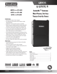
PRODUCT IDENTIFICATION
The model and manufacturing number are used for positive identification of component parts used in manufacturing.
Please use these numbers when requesting service or parts information.
G
C
V
C
PRODUCT
TYPE:
G: Goodman®
A: Amana®
Brand Gas
9
070
4
C
A
ADDITIONAL
FEATURES:
N: Natural Gas
X: Low NOx
AFUE
9: 90%
95: 95%
SUPPLY TYPE:
C: Counterflow/
Horizontal
M: Upflow/
Horizontal
X
COMMUNICATION
FEATURE:
C: 4-wire
Communication
Ready
CABINET
WIDTH:
B: 17-1/2"
C: 21"
D: 24-1/2"
A
MINOR
REVISION
LEVEL
A: Initial Release
MAJOR
REVISION
LEVEL
A: Initial Release
AIRFLOW
CAPABILITY:
3: 1200
4: 1600
5: 2000
FURNACE TYPE:
V: Variable Speed
NOMINAL INPUT:
045: 45,000 Btuh
070: 70,000 Btuh
071: 70,000 Btuh
090: 90,000 Btuh
091: 90,000 Btuh
115: 115,000 Btuh
WARNING
HIGH VOLTAGE!
Disconnect ALL power before servicing or installing this unit. Multiple power
sources may be present. Failure to do so may cause property damage, personal
injury or death.
Goodman will not be responsible
for any injury or property damage
arising from improper service or service procedures. If
you install or perform service on this unit, you assume
responsibility for any personal injury or property damage
which may result. Many jurisdictions require a license to
install or service heating and air conditioning equipment.
WARNING
2
Installation and repair of this unit
should be performed ONLY by individuals meeting the requirements of an "entry level technician", at a minimum, as specified by the Air-Conditioning,
Heating, and Refrigeration Institute (AHRI). Attempting to
install or repair this unit without such background may
result in product damage, personal injury or death.
WARNING
PRODUCT IDENTIFICATION
The model and manufacturing number are used for positive identification of component parts used in manufacturing. Please
use these numbers when requesting service or parts information.
GMVC950453BXAA
GMVC950704CXAA
GMVC950905CXAA
GMVC950905DXAA
GMVC951155DXAA
AMVC950453BXAA
AMVC950704CXAA
AMVC950905CXAA
AMVC950905DXAA
AMVC951155DXAA
GCVC90704CXAA
GCVC90905DXAA
GCVC91155DXAA
ACVC90704CXAA
ACVC90905DXAA
GMVC950453BXAB
GMVC950704CXAB
GMVC950905DXAB
GMVC951155DXAB
GCVC90704CXAB
GCVC90905DXAB
GCVC91155DXAB
AMVC950453BXAB
AMVC950704CXAB
AMVC950905DXAB
AMVC951155DXAB
ACVC90704CXAB
ACVC90905DXAB
ACVC950714CXAA
ACVC950915DXAA
GCVC950714CXAA
GCVC950915DXAA
WARNING
The United States Environmental Protection Agency (“EPA”) has issued various regulations regarding the introduction and disposal of refrigerants introduced into this unit. Failure to follow
these regulations may harm the environment and can lead to the imposition of substantial fines.
These regulations may vary by jurisdiction. Should questions arise, contact your local EPA office.
Do not connect or use any device
that is not design certified by
Goodman for use with this unit.
Serious property damage, personal injury, reduced unit
performance and/or hazardous conditions may result
from the use of such non-approved devices.
WARNING
To prevent the risk of property
damage, personal injury, or death,
do not store combustible materials or use gasoline or
other flammable liquids or vapors in the vicinity of this
appliance.
WARNING
3
PRODUCT DESIGN
The GCVC9, GCVC95, GMVC95, AMVC95, ACVC9 and
ACVC95 furnaces are equipped with an electronic ignition
device to light the burners and an induced draft blower to
exhaust combustion products.
An interlock switch prevents furnace operation if the blower
door is not in place. Keep the blower access doors in place
except for inspection and maintenance.
These furnaces are also equipped with a self-diagnosing electronic control module. In the event a furnace component is
not operating properly, the control module's dual 7-segment
LED's will display an alpha-numeric code, depending upon
the problem encountered. These LED's may be viewed
through the observation window in the blower access door.
Refer to the Troubleshooting Chart for further explanation of
the LED codes and Abnormal Operation - Integrated Ignition Control section in the Service Instructions for an explanation of the possible problem.
The rated heating capacity of the furnace should be greater
than or equal to the total heat loss of the area to be heated.
The total heat loss should be calculated by an approved
method or in accordance with “ASHRAE Guide” or “Manual
J-Load Calculations” published by the Air Conditioning Contractors of America.
*Obtain from: American National Standards Institute 1430
Broadway New York, NY 10018
Location Considerations
The furnace should be as centralized as is practical
with respect to the air distribution system.
•
Do not install the furnace directly on carpeting, tile, or
combustible material other than wood flooring.
•
When suspending the furnace from rafters or joists,
use 3/8" threaded rod and 2” x 2” x 1/8” angle as
shown in the Installation and Service Instructions. The
length of the rod will depend on the application and
clearance necessary.
•
When installed in a residential garage, the furnace
must be positioned so the burners and ignition source
are located not less than 18 inches (457 mm) above
the floor and protected from physical damage by vehicles.
Notes:
1. Installer must supply one or two PVC pipes: one for combustion air (optional) and one for the flue outlet (required).
Vent pipe must be either 2” or 3” in diameter, depending
upon furnace input, number of elbows, length of run and
4
2. Line voltage wiring can enter through the right or left side
of the furnace. Low voltage wiring can enter through the
right or left side of furnace.
3. Conversion kits for propane gas and high altitude natural
and propane gas operation are available. See High Altitude Derate chart for details.
4. Installer must supply the following gas line fittings, depending on which entrance is used:
Left -- Two 90° Elbows, one close nipple, straight pipe
Right -- Straight pipe to reach gas valve.
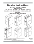
Accessibility Clearances (Minimum)
*MVC95* MINIMUM CLEARANCES TO COMBUSTIBLE MATERIALS
(INCHES)
POSITION* FRONT
SIDES
REAR
TOP
FLUE
FLOOR
Upflow
3
0
0
1
0
C
Horizontal
Alcove
6
0
4
0
C
*=
All positioning is determined as installed unit is viewed from the front.
C= If placed on combustible floor, floor MUST be wood only.
NC= For instalaltion on non-combustible floors only. A combustible
subbase must be used for installations on combustible flooring.
*CVC9 MINIMUM CLEARANCES TO COMBUSTIBLE MATERIALS
(INCHES)
POSITION* FRONT
SIDES
REAR
TOP
FLUE
FLOOR
Upflow
1
0
0
1
0
NC
Horizontal
Alcove
6
0
4
0
C
*=
All positioning is determined as installed unit is viewed from the front.
C= If placed on combustible floor, floor MUST be wood only.
NC= For instalaltion on non-combustible floors only. A combustible
subbase must be used for installations on combustible flooring.
Alcove Illustration
REAR
SIDE
•
installation (1 or 2 pipes). The optional Combustion Air
Pipe is dependent on installation/code requirements and
must be 2” or 3” diameter PVC.
SIDE
General Operation
Models covered by this manual come with a new 4-wire communicating PCB. When paired with a compatible communicating indoor unit and a CTK01AA communicating thermostat, these models can support 4-wire communication protocol and provide more troubleshooting information. These
models are also backward compatible with the legacy thermostat wiring.
ALCOVE
24" at front is required for servicing or cleaning.
Note: In all cases accessibility clearance shall take
precedence over clearances from the enclosure where
accessibility clearances are greater. All dimensions are
given in inches.
High Altitude Derate
When this furnace is installed at high altitude, the appropriate High Altitude orifice kit must be installed. This is re-
PRODUCT DESIGN
quired due to the natural reduction in the density of both the
gas fuel and combustion air as altitude increases. The kit
will provide the proper design certified input rate within the
specified altitude range.
High altitude kits are purchased according to the installation altitude and usage of either natural or propane gas. Refer
to the chart above for a tabular listing of appropriate altitude
ranges and corresponding manufacturer’s high altitude Natural Gas and Propane Gas kits. For a tabular listing of appropriate altitude ranges and corresponding manufacturer's High
Altitude Pressure Switch kits, refer to either the Pressure
Switch Trip Points & Usage Chart in this manual or the Accessory Charts in Service Instructions.
of time before stepping up to high stage to satisfy the
thermostat’s call for heat. The delay period prior to stepping
up can be set at either a fixed 5 minute time delay or a load
based variable time between 1 and 12 minutes (AUTO mode).
If the AUTOmode is selected, the control averages the cycle
times of the previous three cycles and uses the average to
determine the time to transition from low stage to high stage.
To use a single-stage thermostat, turn off power to the furnace, move the thermostat selection DIP switch to the OFF
position. Set the desired transition time by setting the transition delay DIP switch to the desired ON/OFF position. Turn
power back on. Refer to the following figure.
ON
OFF
Move to the ON position
to select two-stage
thermostat or OFF to
select single stage
thermostat
Heat OFF Delay
DIP Switches
Single Stage Thermostat
A single-stage thermostat with only one heating stage may
be used to control this furnace. The application of a singlestage thermostat does not offer “true” thermostat-driven twostage operation, but provides a timed transition from low to
high fire. The furnace will run on low stage for a fixed period
3
Thermostat
4
Stage Delay
Move to the ON position
to select Auto transition
delay or OFF for 5 minute
transition delay
S1
"S TANDARD" and "HIGH ALTITUDE " K ITS
LP M-05 *(1)
LP M-06 *(2)
# 55 Orifice
No
Chan ge
GM VC 9509 05C X*
A MV C95 0905 CX*
No
Ch ange
LP M-05 *(1)
LP M-06 *(2)
# 55 Orifice
No
Chan ge
GM VC 9509 05D X*
GM VC 9511 55D X*
A MV C95 0905 DX*
A MV C95 1155 DX*
No
Ch ange
GCV C90 704 CX*
GCV C90 905 DX*
GCV C91 155 DX*
A CVC 9070 4CX *
A CVC 9090 5DX *
No
Ch ange
GCV C95 0714 CX*
GCV C95 0915 DX*
A CVC9 507 14CX *
A CVC9 509 15DX *
No
Ch ange
2
LP M-05 *(1)
HANG13 HA LP11
#56
# 44
Orifice
Orifice
N /A
N/A
ID Bl wr
P res sure
Switch
HAP S 28
N/A
9 ,001 - 11,0 00 Fe et
Ga s Orific es
Propane
Propane
No
Ch ange
Ga s Ori fices
Propane
Natural
GMV C95 0453 BX *
GM VC 9507 04C X*
AM VC9 5045 3B X*
A MV C95 0704 CX*
Furnace
1
ID B lwr
P re ssure
S witch
Natural
Gas Orifice s
7,00 1 - 9,0 00 Fe et
Natural
0 - 7,00 0 Fee t
(Standard Altitude)
ID Blw r
P res sure
Sw itc h
HA NG14 HA LP1 1
#56
HAP S2 8
# 45
Orifice
Orif ice
N/ A
N /A
N/A
No
Chan ge
HANG13 HA LP11
#56
# 44
Orifice
Orifice
HAP S 29
HA NG14 HA LP1 1
#56
HAP S2 9
# 45
Orifice
Orif ice
(2)
No
Chan ge
HANG13 HA LP11
#56
# 44
Orifice
Orifice
HAP S 29
HA NG14 HA LP1 1
#56
HAP S3 1
# 45
Orifice
Orif ice
LP M-05 *(1)
LP M-06 *(2)
# 55 Orifice
No
Chan ge
LP M-06 *(2)
# 55 Orifice
LP M-05 *(1)
LP M-06 *
# 55 Orifice
N /A
N/A
N/A
N/ A
N /A
N/A
LPM-05* supports White-Rodgers 2-stage valves only
LPM-06* supports Honeywell and White-Rodgers 2-stage valves
5
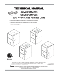
COMPONENT IDENTIFICATION
9
7
5
10
10
32
4
11
3
12
3
*
2
11
25
24
*
*
28
13
15
*
*
1
*
*
14
16 17
18
31
18
19
19
20
3
3
17
15
31
21
16
30
18
18
19
28
14
29
20
20
19
20
13
12
2 21
23
26
27
25
Upflow/Horizontal
9
7
8
7
6 4
1
Counterflow /Horizontal
1 Two-Stage Gas Valve
18 Coil Front Cover Pressure Tap
2 Gas Line Entrance (Alternate)
19 Coil Front Cover Drain Port
3 Pressure Switch(es)
20 Drain Line Penetrations
4 Gas Manifold
21 Drain Trap
5 Combustion Air Intake Connection
22 Blower Door Interlock Switch
6 Hot Surface Igniter
23 Inductor (Not All Models)
7 Rollout Limit
24 Two-Stage Integrated Control Module
8 Burners
9 Flame Sensor
(with fuse and diagnostic LED)
25 24 Volt Thermostat Connections
10 Flue Pipe Connection
26 Transformer (40 VA)
11 Flue Pipe
27 ECM Variable Speed Circulator Blower
12 Primary Limit
28 Auxiliary Limit
13 Gas Line Entrance
29 Junction Box
14 Flue Pipe Connection (Alternate)
30 Electrical Connection Inlets
15 Rubber Elbow
31 Coil Front Cover
16 Two-Speed Induced Draft Blower
32 Combustion Air Inlet Pipe (*CVC9/95 only)
17 Electrical Connection Inlets (Alternate)
6
23
26
27
BLOWER COMPARTMENT
8
7
*
BLOWER COMPARTMENT
6
*
BURNER COMPARTMENT
5
LEFT SIDE
VIEW
23 9/16
BOTTOM KNOCK-OUT
1 3/4
2 5/8
11 3/4
17 1/2
21
24 1/2
UNITS
0453BX*
0704CX*
0905CX*
0905DX*
1155DX*
SMALL
MEDIUM
LARGE
A
BOTTOM KNOCK-OUT
C
CABINET
SIZE
30 1/4
19 3/16
DRAIN
TRAP
AIR INTAKE
PIPE
2" PVC
B
(DISCHARGE AIR)
A
20 3/8
16 3/8
12 3/8
C
32 13/16
18 5/8
14 5/8
12 5/8
D
19 3/16
4 1/8
All dimensions are in inches.
23
19
15
B
2
CONDENSATE
DRAIN TRAP
w/ 3/4" PVC
DISCHARGE
(RIGHT OR
LEFT SIDE)
2 11/16
VENT/FLUE PIPE
2" PVC
1 3/4
RIGHT SIDE
DRAIN LINE
HOLES
STANDARD GAS
SUPPLY HOLE
AIR
DISCHARGE
RIGHT SIDE
VIEW
SIDE CUT-OUT
HIGH VOLTAGE
ELECTRICAL HOLE
LOW VOLTAGE
ELECTRICAL HOLE
DRAIN
TRAP
NOTE: Airflow area will be reduced by approximately 18% if duct flanges are not unfolded. This could cause performance issues and noise issues.
1 1/2
1 5/8
SIDE CUT-OUT
HIGH VOLTAGE
ELECTRICAL HOLE
LOW VOLTAGE
ELECTRICAL HOLE
LEFT SIDE
DRAIN LINE
HOLES
19 3/4
AIR
DISCHARGE
PRODUCT DIMENSIONS
GMVC95/AMVC95___X*
7
8
A
21
24 1/2
UNITS
0704CX*
0714CX*
0905DX*
0915DX*
1155DX*
CABINET
SIZE
MEDIUM
LARGE
9 13/16
11 1/2
15 1/2
28 5/16
23
19
B
18 5/8
14 5/8
D
All dimensions are in inches.
20 3/8
16 3/8
C
DISCHARGE AIR
E
FOLDED FLANGES
UNFOLDED FLANGES
2
20 7/8
14
18 13/16
17 1/2
E
28 5/16
CONDENSATE
DRAIN TRAP
w/ 3/4" PVC
DISCHARGE
(RIGHT OR
LEFT SIDE)
2 11/16
1 3/4
VENT/FLUE PIPE
2" PVC
7 3/8
RIGHT SIDE
DRAIN LINE
HOLES
AIR
DISCHARGE
ALTERNATE GAS
SUPPLY HOLE
DRAIN
TRAP
HIGH VOLTAGE
ELECTRICAL HOLE
LOW VOLTAGE
ELECTRICAL HOLE
NOTE: Airflow area will be reduced by approximately 18% if duct flanges are not unfolded. This could cause performance issues and noise issues.
AIR
DISCHARGE
20 5/32
FOLDED FLANGES
18 5/8
UNFOLDED FLANGES
STANDARD GAS
SUPPLY HOLE
LEFT SIDE
DRAIN LINE
HOLES
DRAIN
TRAP 2 5/8
HIGH VOLTAGE
ELECTRICAL HOLE
LOW VOLTAGE
ELECTRICAL HOLE
1 3/4
AIR INTAKE
PIPE
2" PVC
A
B
(RETURN AIR)
C
PRODUCT DIMENSIONS
GCVC9/ACVC9_____X*
PRODUCT DESIGN
PRESSURE SWITCH TRIP POINTS AND USAGE CHART
MODEL
NEGATIVE PRESSURE
ID BLOWER
WITH FLUE
NOT FIRING
TYPICAL SEA LEVEL
NEGATIVE PRESSURE
ID BLOWER
WITH FLUE
FIRING
TYPICAL SEA LEVEL
NEGATIVE PRESSURE
COIL COVER
WITH FLUE
NOT FIRING
TYPICAL SEA LEVEL
NEGATIVE PRESSURE
COIL COVER
WITH FLUE
FIRING
TYPICAL SEA LEVEL
DATA(1)
DATA(2)
DATA(1)
DATA(2)
LOW FIRE
HIGH FIRE
LOW FIRE
HIGH FIRE
LOW FIRE
HIGH FIRE
LOW FIRE
HIGH FIRE
GMVC950453BX*
GMVC950704CX*
AMVC950453BX*
AMVC950704CX*
-0.45
-0.90
-0.50
-0.95
-0.25
-0.25
-0.25
-0.25
GMVC950905CX*
AMVC950905CX*
-0.75
-1.85
-.060
-1.70
-0.10
-0.10
-0.10
-0.10
GMVC950905DX*
GMVC951155DX*
AMVC950905DX*
AMVC951155DX*
-0.65
-1.20
-0.70
-1.25
-0.25
-0.25
-0.25
-0.25
GCVC90704CX*
ACVC90704CX*
-0.35
-0.70
-0.20
-0.55
-0.52
-0.52
-0.37
-0.37
GCVC950714CX*
ACVC950714CX*
-0.95
-1.75
-1.00
-1.80
-0.10
-0.10
-0.10
-0.10
GCVC90905DX*
ACVC90905DX*
-0.35
-0.70
-0.20
-0.55
-0.52
-0.52
-0.37
-0.37
GCVC950915DX*
ACVC950915DX*
-0.95
-1.75
-1.00
-1.80
-0.10
-0.10
-0.10
-0.10
GCVC91155DX*
-0.35
-0.70
-0.20
-0.55
-0.52
-0.52
-0.37
-0.37
(1) Data given is least negative pressure required for pressure switch to close.
(2) Data given is least negative pressure required for pressure switch to remain closed.
Note: The typical sea level negative pressure data represents the minimum pressures expected. Shorter length of flue pipe or single pipe systems compared to
dual pipe systems should show higher (greater negative) pressures.
9
10
-0.10
-0.10
-0.37
-0.10
-0.37
-0.10
-0.37
GMVC 950905CX*
AMVC950905CX*
GMVC 950905DX*
GMVC 951155DX*
AMVC950905DX*
AMVC951155DX*
GCVC90704C X*
ACVC90704CX*
GCVC950714CX*
ACVC950714CX*
GCVC90905D X*
ACVC90905DX*
GCVC950915DX*
ACVC950915DX*
GCVC91155D X*
-0.37
-0.10
-0.37
-0.10
-0.37
-0.10
-0.10
-0.10
20197313
0130F00070
20197313
0130F00070
20197313
20197308
0130F00070
20197308
COIL COVER
PRESSU RE
SWITCH
PART #
-0.20
-0.80
-0.20
-0.80
-0.20
-0.50
-0.60
-0.30
-0.55
-1.60
-0.55
-1.60
-0.55
-1.10
-1.70
-0.75
LOW FIR E HIGH FIRE
TRIP POINT
ID BLOWER
PRESSURE SWITCH
11177118
0130F00100
11177118
0130F00100
11177118
11177114
0130F00111
11177113
ID BLOWER
PRESSURE
SWITCH
PART #
TRIP POINT
ID BLOWER
PRESSURE SWITCH
-0.37
N/A
-0.37
N/A
-0.37
-0.10
N/A
-0.10
-0.37
N/A
-0.37
N/A
-0.37
-0.10
N/A
-0.10
-0.15
N/A
-0.15
N/A
-0.15
-0.38
N/A
-0.22
-0.30
N/A
-0.30
N/A
-0.30
-0.82
N/A
-0.55
LOW FIRE HIGH FIRE LOW FIR E HIGH FIRE
TRIP POINT
COIL COVER
PRESSU RE SWITCH
7,001 ft. to 11,000 ft.
Note: All negative pressure readings are in inches of water column (" w.c.).
Note: Replacement pressure switch number is listed below high altitude kit number.
Note: All installations above 7,000 ft. require a pressure switch change. For installations in Canada the *MVC95 & *CVC 9/95 furnaces are certified only to 4500 ft.
-0.10
LOW FIRE HIGH FIRE
GMVC 950453BX*
GMVC 950704CX*
AMVC950453BX*
AMVC950704CX*
MODEL
TRIP POINT
COIL COVER
PRESSURE SWITCH
0 to 7,000 ft.
PRESSURE SWITCH TRIP POINTS AND USAGE CHART
HAPS31
N/A
HAPS31
N/A
HAPS31
HAPS29
11177116
N/A
HAPS28
11177115
HIGH
ALTITUDE
KIT
PRODUCT DESIGN
PRODUCT DESIGN
PRIMARY LIMIT
Part Number
20162903
20162904
20162905
20162907
20162908
0130F00105
Open Setting (°F)
160
150
145
155
170
130
GMVC950453BX*
AMVC950453BX*
---
---
1
---
---
---
GMVC950704CX*
AMVC950704CX*
---
---
---
1
---
---
GMVC950905CX*
AMVC950905CX*
---
---
---
---
---
1
GMVC950905DX*
AMVC950905DX*
---
---
1
---
---
---
GMVC951155DX*
AMVC951155DX*
---
1
---
---
---
---
GCVC90704CX*
ACVC90704CX*
1
---
---
---
---
---
GCVC950714CX*
ACVC950714C X*
---
1
---
---
---
---
GCVC90905DX*
ACVC90905DX*
---
---
---
---
1
---
GCVC950915DX*
ACVC950915D X*
---
---
---
---
---
1
GCVC91155DX*
----
----
1
----
----
---
R OLLOUT LIMIT SWITCHES
Part N um ber
10123512
10123517
10123518
10123533
10123534
10123537
Open Setting (°F)
325
210
170
200
220
190
GMVC950453BX*
AMVC950453B X*
---
---
1
---
---
---
GMVC950704CX*
AMVC950704C X*
---
---
---
2
---
---
GMVC950905CX*
AMVC950905C X*
---
---
---
2
---
---
GMVC950905DX*
AMVC950905D X*
---
---
---
---
---
2
GMVC951155DX*
AMVC951155D X*
---
---
---
2
---
---
GCVC90704CX*
AC VC90704CX*
----
---
---
---
2
---
GCVC 950714C X*
ACVC950714CX*
----
2
----
----
----
----
GCVC90905DX*
AC VC90905DX*
---
2
---
---
---
---
GCVC 950915D X*
ACVC950915DX*
---
2
---
---
---
---
GCVC91155DX*
----
2
----
----
----
---
11
PRODUCT DESIGN
AUXILIARY LIMIT SWITCHES
12
Part Number
10123534
10123535
10123537
10123536
10123533
0130F00038
Open Setting (°F)
220
150
190
180
200
120
GMVC950453BX*
AMVC950453BX*
---
2
---
---
---
---
GMVC950704CX*
AMVC950704CX*
---
---
2
---
---
---
GMVC950905CX*
AMVC950905CX*
---
---
---
---
---
2
GMVC950905DX*
AMVC950905DX*
---
---
---
2
---
---
GMVC951155DX*
AMVC951155DX*
---
---
---
---
2
---
GCVC90704CX*
ACVC90704CX*
2
---
---
---
---
---
GCVC 950714CX*
ACVC950714CX*
---
---
---
---
---
2
GCVC90905DX*
ACVC90905DX*
---
---
---
2
---
---
GCVC 950915DX*
ACVC950915DX*
---
---
---
---
---
2
GCVC 911555DX*
---
---
---
2
---
---
PRODUCT DESIGN
Coil Matches:
A large array of Amana® brand coils are available for use with the GCVC9 and ACVC9 furnaces, in either counterflow or
horizontal applications & with GMVC95 and AMVC95 furnaces, in either upflow or horizontal applications. These coils are
available in both cased and uncased models (with the option of a field installed TXV expansion device). These 92%+ and
95%+ furnaces match up with the existing Amana® brand coils as shown in the chart below.
Coil Matches (for Goodman® and Amana® Brand units using R22 and R-410A):
C
A
P
F
1824
A
6
EXPANSION
DEVICE:
F: Flowrater
PRODUCT
TYPE:
C: Indoor Coil
CABINET FINISH:
U: Unpainted
P: Painted
N: Unpainted Case
APPLICATION
A: Upflow/Downflow Coil
H: Horizontal A Coil
S: Horizontal Slab Coil
A
REVISION
A: Revision
REFRIGERANT
CHARGE:
6: R-410A or R-22
2: R-22
4: R-410a
NOMINAL WIDTH FOR GAS FURNACE
A: Fits 14" Furnace Cabinet
B: Fits 17 1/2" Furnace Cabinet
C: Fits 21" Furnace Cabinet
D: Fits 24 1/2" Furnace Cabinet
N: Does Not Apply (Horizontal Slab Coils)
NOMINAL CAPACITY RANGE
@ 13 SEER
1824: 1 1/2 to 2 Tons
3030: 2 1/2 Tons
3636: 3 Tons
3642: 3 to 3 1/2 Tons
3743: 3 to 3 1/2 Tons
4860: 4 & 5 Tons
4961: 4 & 5 Tons
• All CAPF coils in B, C, & D widths have insulated blank off plates for use with one size smaller furnaces.
• All CAPF coils have a CAUF equivalent.
• All CHPF coils in B, C & D heights have an insulated Z bracket for use with one size smaller furnace.
• All proper coil combinations are subject to being ARI rated with a matched outdoor unit.
13
PRODUCT DESIGN
Thermostats:
ComfortNet™ CTK01A* Thermostat Kit
Filters:
Filters are required with this furnace and must be provided by the installer. The filters used must comply with UL900 or
CAN/ULCS111 standards. Installing this furnace without filters will void the unit warranty
Upflow Filters
Return air filters may be installated at the furnace side and/or bottom return openings. The furnace bottom return opening
and side openings will accommodate the following filter sizes depending on cabinet size:
Side Re turn Ope ning(s)
Bottom Re turn Ope ning
Cabinet
W idth
(in.)
Nominal
Filter Size
(in.)
Approx.
Flow Area
(in2 )
Cabinet
W idth
(in.)
Nominal
Filter Size
(in.)
Approx.
Flow Area
(in2 )
All
16 x 25 x 1
400
17-1/2
14 x 25 x 1
350
21
16 x 25 x 1
400
24-1/2
20 x 25 x 1
500
Refer to Minimum Filter Area tables to determine filter area requirement. NOTE: Filters can also be installed elsewhere in
the duct system such as a central return.
Input__Airflow
U PFLOW
COOLING A IRFLOW REQU IREMEN T (CFM)
600
800
1000
1200
1400
1600
1800
2000
04 53__X*
415*
415*
48 0
576
---
---
---
---
07 04__X*
---
---
636*
636*
672
768
---
---
09 05__X*
---
---
---
826*
826*
826*
864
960
11 55__X*
---
---
---
875*
875*
875*
875*
960
Input
Airflow
COUNTER FLOW
COOLING A IRFLOW REQU IREMEN T (CFM)
600
800
1000
1200
1400
1600
1800
2000
0704 __X*
0714 __X*
---
---
634*
634*
672
768
---
---
0905 __X*
0915 __X*
---
---
---
819*
819*
819*
864
960
11 55__X*
---
---
---
860*
860*
860*
864
960
*Minimum filter area dictated by heating airflow requirement.
Disposable Minimum Filter Area (in2)
[Based on a 300 ft/min filter face velocity]
14
PRODUCT DESIGN
Input__Airflow
U PFLOW
COOLING A IRFLOW REQU IREMEN T (CFM)
600
800
1000
1200
1400
1600
1800
2000
04 53__X*
207*
207*
24 0
288
---
---
---
---
07 04__X*
---
---
318*
318*
336
384
---
---
09 05__X*
---
---
---
413*
413*
413*
432
480
11 55__X*
---
---
---
437*
437*
437*
432
480
Input
Airflow
COUNTER FLOW
COOLING A IRFLOW REQU IREMEN T (CFM)
600
800
1000
1200
1400
1600
1800
2000
0704 __X*
0714 __X*
---
---
316*
316*
336
384
---
---
0905 __X*
0915 __X*
---
---
---
409*
409*
409*
432
480
11 55__X*
---
---
---
430*
430*
430*
432
480
*Minimum filter area dictated by heating airflow requirement.
Disposable Minimum Filter Area (in2)
[Based on a 600 ft/min filter face velocity]
Counterflow Filters
Return air filters may be installated at the at the counterflow top return. A field supplied center filter support must be provided
by the installer in order to use the top return. The furnace will accommodate the following counterflow top return filter sizes
depending on cabinet size:
Counterflow Top Return
Return Air
Cabinet Width
Filter Area
2
Qty
(in )
Optional
Access
Door
Filter Size Dimension "A"
(in)
(in)
17 1/2
"A"
Min
21
14.2
600
2
15 X 20 X 1
13.0
24 1/2
11.3
17 1/2
19.7
21
800
2
20 X 20 X 1
24 1/2
17.7
17 1/2
21
24 1/2
18.8
25.0
1000
2
25 X 20 X 1
24.3
23.4
Refer to Minimum Filter Area tables to determine filter area requirement. NOTE: Filters can also be installed elsewhere
in the duct system such as a central return.
15
FURNACE SPECIFICATIONS
MODEL
GMVC95
GMVC950453BX* GMVC950704CX* GMVC950905CX* GMVC950905DX* GMVC951155DX*
Btuh Input (US) High Fire
46,000
69,000
92,000
92,000
115,000
Output (US) High Fire
44,300
66,900
88,800
88,800
111,100
Btuh Input (US) Low Fire
32,000
48,000
64,000
64,000
80,000
Output (US) Low Fire
30,800
46,400
61,700
61,700
77,400
95%
95%
95%
95%
95%
.10 - .50
.10 - .50
.10 - .50
.10 - .50
.10 - .50
30 - 60
30 - 60
30 - 60
30 - 60
35 - 65
High Stage Pressure Switch Trip Point (" w.c.)
-0.75
-0.75
-1.70
-1.10
-1.10
Low Stage Pressure Switch Trip Point (" w.c.)
-0.30
-0.30
-0.60
-0.50
-0.50
Front Cover Pressure Switch Trip Point (" w.c)
-0.10
-0.10
-0.10
-0.10
-0.10
Blower Wheel (D" x W")
10 x 8
10 x 10
11 x 10
11 x 10
11 x 10
1/2
3/4
1
1
1
A.F.U.E.
Rated External Static (" w.c.)
Temperature Rise (°F)
Blower Horsepower
Blower Speeds
Refer to airflow charts in this manual.
Max CFM @ 0.5 E.S.P.
Power Supply
Minimum Circuit Ampacity (MCA)
Maximum Overcurrent Device
115-60-1
115-60-1
115-60-1
115-60-1
115-60-1
11.3
14.1
14.4
14.4
14.4
15
15
15
15
15
Transformer (VA)
40
40
40
40
40
Heat Anticipator (Amps)
0.7
0.7
0.7
0.7
0.7
Primary Limit Setting (°F)
145
155
130
145
150
Auxiliary Limit Setting (°F)
150
190
120
180
200
Rollout Limit Setting (°F)
170
200
200
190
200
30 secs.
30 secs.
30 secs.
30 secs.
30 secs.
150 secs.
150 secs.
150 secs.
150 secs.
150 secs.
5 secs.
5 secs.
5 secs.
5 secs.
5 secs.
Off Cooling
45 secs.
45 secs.
45 secs.
45 secs.
45 secs.
Fan Delay On - Fan Only
5 secs.
5 secs.
5 secs.
5 secs.
5 secs.
7 / 11
7 / 11
7 / 11
7 / 11
7 / 11
Manifold Pressure (Natural/Propane) High Stage (" w.c.)
3.5 / 10
3.5 / 10
3.5 /10
3.5 /10
3.5 /10
Manifold Pressure (Natural/Propane) Low Stage ("w.c.)
1.9 / 6.0
1.9 / 6.0
1.9 / 6.0
1.9 / 6.0
1.9 / 6.0
Orifice Size (Natural/Propane)
#43 / #55
#43 / #55
#43 / #55
#43 / #55
#43 / #55
Number of Burners
2
3
4
4
5
Vent Connector Diameter (inches)
2
2
2
2
2
Combustion Air Connector Diameter (inches)
2
2
2
2
2
133
157
172
172
184
Fan Delay On Heating
Off Heating *
Fan Delay On Cooling
Gas Supply Pressure (Natural/Propane) (" w.c.)
Shipping Weight (lbs.)
* Off Heating - This fan delay timing is adjustable (90, 120, 150 or 180 seconds), 150 seconds as shipped.
1.
These furnaces are manufactured for natural gas operation. Optional Kits are available for conversion to propane gas operation.
2.
For elevations above 2000 ft. the rating should be reduced by 4% for each 1000 ft. above sea level. The furnace must not be derated, orifice
changes should only be made if necessary for altitude.
3.
The total heat loss from the structure as expressed in TOTAL BTU/HR must be calculated by the manufactures method in accordance with the
"A.S.H.R.A.E. GUIDE" or "MANUAL J-LOAD CALCULATIONS" published by the AIR CONDITIONING CONTRACTORS OF AMERICA. The total
heat loss calculated should be equal to or less than the heating capacity. Output based on D.O.E. test procedures, steady state efficiency times
output.
4.
Minimum Circuit Ampacity calculated as: (1.25 x Circulator Blower Amps) + I.D. Blower Amps.
16
FURNACE SPECIFICATIONS
MODEL
AMVC95
AMVC950453BX* AMVC950704CX* AMVC950905CX* AMVC950905DX* AMVC951155DX*
Btuh Input (US) High Fire
46,000
69,000
92,000
92,000
115,000
Output (US) High Fire
44,300
66,900
88,800
88,800
111,100
Btuh Input (US) Low Fire
32,000
48,000
64,000
64,000
80,000
Output (US) Low Fire
30,800
46,400
61,700
61,700
77,400
99%
95.5%
95.7%
95.7%
95.8%
.10 - .50
.10 - .50
.10 - .50
.10 - .50
.10 - .50
30 - 60
30 - 60
30 - 60
30 - 60
35 - 65
High Stage Pressure Switch Trip Point (" w.c.)
-0.75
-0.75
-1.70
-1.10
-1.10
Low Stage Pressure Switch Trip Point (" w.c.)
-0.30
-0.30
-0.60
-0.50
-0.50
Front Cover Pressure Switch Trip Point (" w.c)
-0.10
-0.10
-0.10
-0.10
-0.10
Blower Wheel (D" x W")
10 x 8
10 x 10
11 x 10
11 x 10
11 x 10
1/2
3/4
1
1
1
A.F.U.E.
Rated External Static (" w.c.)
Temperature Rise (°F)
Blower Horsepower
Blower Speeds
Refer to airflow charts in this manual.
Max CFM @ 0.5 E.S.P.
Power Supply
115-60-1
115-60-1
115-60-1
115-60-1
115-60-1
11.3
14.1
14.4
14.4
14.4
15
15
15
15
15
Transformer (VA)
40
40
40
40
40
Heat Anticipator (Amps)
0.7
0.7
0.7
0.7
0.7
Primary Limit Setting (°F)
145
155
130
145
150
Auxiliary Limit Setting (°F)
150
190
120
180
200
Rollout Limit Setting (°F)
170
200
200
190
200
30 secs.
30 secs.
30 secs.
30 secs.
30 secs.
150 secs.
150 secs.
150 secs.
150 secs.
150 secs.
5 secs.
5 secs.
5 secs.
5 secs.
5 secs.
Off Cooling
45 secs.
45 secs.
45 secs.
45 secs.
45 secs.
Fan Delay On - Fan Only
5 secs.
5 secs.
5 secs.
5 secs.
5 secs.
7 / 11
7 / 11
7 / 11
7 / 11
7 / 11
Manifold Pressure (Natural/Propane) High Stage (" w.c.)
3.5 / 10
3.5 / 10
3.5 /10
3.5 /10
3.5 /10
Manifold Pressure (Natural/Propane) Low Stage ("w.c.)
1.9 / 6.0
1.9 / 6.0
1.9 / 6.0
1.9 / 6.0
1.9 / 6.0
Orifice Size (Natural/Propane)
#43 / #55
#43 / #55
#43 / #55
#43 / #55
#43 / #55
Number of Burners
2
3
4
4
5
Vent Connector Diameter (inches)
2
2
2
2
2
Minimum Circuit Ampacity (MCA)
Maximum Overcurrent Device
Fan Delay On Heating
Off Heating *
Fan Delay On Cooling
Gas Supply Pressure (Natural/Propane) (" w.c.)
Combustion Air Connector Diameter (inches)
Shipping Weight (lbs.)
2
2
2
2
2
133
157
172
172
184
* Off Heating - This fan delay timing is adjustable (90, 120, 150 or 180 seconds), 150 seconds as shipped.
1.
These furnaces are manufactured for natural gas operation. Optional Kits are available for conversion to propane gas operation.
2.
For elevations above 2000 ft. the rating should be reduced by 4% for each 1000 ft. above sea level. The furnace must not be derated, orifice
changes should only be made if necessary for altitude.
3.
The total heat loss from the structure as expressed in TOTAL BTU/HR must be calculated by the manufactures method in accordance with the
"A.S.H.R.A.E. GUIDE" or "MANUAL J-LOAD CALCULATIONS" published by the AIR CONDITIONING CONTRACTORS OF AMERICA. The total
heat loss calculated should be equal to or less than the heating capacity. Output based on D.O.E. test procedures, steady state efficiency times
output.
4.
Minimum Circuit Ampacity calculated as: (1.25 x Circulator Blower Amps) + I.D. Blower Amps.
17
FURNACE SPECIFICATIONS
MODEL
Btuh Input (US) High Fire
GCVC9
GCVC90704CX*
GCVC90905DX*
GCVC91155DX*
69,000
92,000
115,000
Output (US) High Fire
65,300
86,500
109,000
Btuh Input (US) Low Fire
48,000
64,000
80,000
Output (US) Low Fire
45,000
60,100
77,400
A.F.U.E.
93.0%
92.0%
93%
.10 - .50
.10 - .50
.10 - .50
30 - 60
30 - 60
40 - 70
High Stage Pressure Switch Trip Point (" w.c.)
-0.55
-0.55
-0.55
Low Stage Pressure Switch Trip Point (" w.c.)
-0.20
-0.20
-0.20
Front Cover Pressure Switch Trip Point (" w.c)
-0.37
-0.37
-0.37
10 x 10
11 x 10
11 x 10
3/4
1
1
Rated External Static (" w.c.)
Temperature Rise (°F)
Blower W heel (D" x W ")
Blower Horsepower
Blower Speeds
Refer to airflow charts in this manual.
Max CFM @ 0.5 E.S.P.
Power Supply
Minimum Circuit Ampacity (MCA)
Maximum Overcurrent Device
115-60-1
115-60-1
115-60-1
14.1
14.4
14.4
15
15
15
Transformer (VA)
40
40
40
Heat Anticipator (Amps)
0.7
0.7
0.7
Primary Limit Setting (°F)
160
170
145
Auxiliary Limit Setting (°F)
220
180
180
Rollout Limit Setting (°F)
220
210
210
30 secs.
30 secs.
30 secs.
150 secs.
150 secs.
150 secs.
5 secs.
5 secs.
5 secs.
Off Cooling
45 secs.
45 secs.
45 secs.
Fan Delay On - Fan Only
5 secs.
5 secs.
5 secs.
7 / 11
7 / 11
7 / 11
Manifold Pressure (Natural/Propane) High Stage (" w.c.)
3.5 / 10
3.5 /10
3.5 /10
Manifold Pressure (Natural/Propane) Low Stage ("w.c.)
1.9 / 6.0
1.9 / 6.0
1.9 / 6.0
Orifice Size (Natural/Propane)
#43 / #55
#43 / #55
#43 / #55
3
4
5
Fan Delay On Heating
Off Heating *
Fan Delay On Cooling
Gas Supply Pressure (Natural/Propane) (" w.c.)
Number of Burners
Vent Connector Diameter (inches)
2
2
2
Combustion Air Connector Diameter (inches)
2
2
2
157
172
175
Shipping W eight (lbs.)
* Off Heating - This fan delay tim ing is adjus table (90, 120, 150 or 180 s econds ), 150 s econds as s hipped.
1.
These furnaces are manufactured for natural gas operation. Optional Kits are available for conversion to propane gas operation.
2.
For elevations above 2000 ft. the rating should be reduced by 4% for each 1000 ft. above sea level. The furnace must not be derated, orifice
changes should only be made if necessary for altitude.
3.
The total heat loss from the structure as expressed in TOTAL BTU/HR must be calculated by the manufactures method in accordance with the
"A.S.H.R.A.E. GUIDE" or "MANUAL J-LOAD CALCULATIONS" published by the AIR CONDITIONING CONTRACTORS OF AMERICA. The total
heat loss calculated should be equal to or less than the heating capacity. Output based on D.O.E. test procedures, steady state efficiency times
output.
4.
Minimum Circuit Ampacity calculated as: (1.25 x Circulator Blower Amps) + I.D. Blower Amps.
18
FURNACE SPECIFICATIONS
MO DEL
GCVC95
G C V C 95 0 71 4 CX *
G C V C9 5 09 1 5D X *
B tu h In p ut (US ) Hig h Fire
69 ,0 0 0
9 2 ,0 00
O u tp ut (US ) Hig h Fire
65 ,3 0 0
8 6 ,5 00
B tu h In p ut (US ) Lo w Fire
48 ,0 0 0
6 4 ,0 00
O u tp ut (US ) Lo w Fire
45 ,0 0 0
6 0 ,1 00
A .F. U.E .
9 5. 0%
95 .0 %
R at ed E x te rn al S t at ic (" w .c .)
.1 0 - . 50
.1 0 - .5 0
Te m p era tu re R is e (° F )
25 - 55
25 - 55
H ig h S ta ge P re s s u re S witc h Trip P o in t (" w .c .)
-1 .6 0
-1 .6 0
L ow S ta g e P res s u re S witc h T rip P o int (" w.c . )
-0 .8 0
-0 .8 0
Fro n t C o v er Pre s s u re S witc h T rip P o in t (" w .c )
-0 .1 0
-0 .1 0
10 x 10
11 x 10
3 /4
1
B low er W h ee l (D " x W ")
B low er Ho rs e po w er
B low er S pe e ds
R e fe r to a irflow c h a rts in th is m an u al.
M a x CF M @ 0. 5 E. S .P .
P o we r S u pp ly
1 15 -6 0-1
11 5 -60 -1
1 1 .2
1 5. 0
15
15
Tra n s fo rm er (V A)
40
40
H ea t An tic ipa to r (A m p s )
0. 7
0 .7
P rim ary Lim it S e ttin g (°F )
1 50
13 0
A u xilia ry L im it S e ttin g (°F )
1 20
12 0
R ollou t L im it S e ttin g (°F )
2 10
21 0
30 s e c s .
3 0 se cs.
1 5 0 s ec s .
1 50 s e c s .
5 se cs.
5 s ec s .
O ff Co o lin g
45 s e c s .
4 5 se cs.
Fa n D ela y O n - F an O nly
5 se cs.
5 s ec s .
7 / 11
7 / 11
M a nifo ld Pre s s u re (Na tu ra l/ P rop a ne ) H igh S t ag e (" w .c . )
3 .5 / 10
3 .5 / 10
M a nifo ld Pre s s u re (Na tu ra l/ P rop a ne ) L o w St ag e ("w .c . )
1 .9 / 6 .0
1 .9 / 6. 0
# 43 / # 55
#4 3 / #5 5
N um b e r o f B u rne rs
3
4
V e nt C on n ec t or Dia m et er (in c h es )
2
2
C om b u s tio n A ir C on n ec t or Dia m et er (in c h es )
2
2
1 57
17 2
M in im um C irc uit A m pa c ity (M C A )
M ax im um O v e rc urre n t D e v ic e
Fa n D ela y O n H ea tin g
O ff He a ting *
Fa n D ela y O n C oo lin g
G a s S u pp ly P re s s ure (N a tu ral/P ro p an e ) (" w .c . )
O rific e S iz e (N a tu ral/P ro p an e )
S h ip pin g W e ig h t (lb s .)
* O ff H ea tin g - T hi s fa n d el a y tim in g is a dju st a b le ( 9 0, 12 0 , 15 0 o r 1 8 0 s ec o nd s) , 1 50 se co n ds as s h i pp e d .
1.
These furnaces are manufactured for natural gas operation. Optional Kits are available for conversion to propane gas operation.
2.
For elevations above 2000 ft. the rating should be reduced by 4% for each 1000 ft. above sea level. The furnace must not be derated, orifice
changes should only be made if necessary for altitude.
3.
The total heat loss from the structure as expressed in TOTAL BTU/HR must be calculated by the manufactures method in accordance with the
"A.S.H.R.A.E. GUIDE" or "MANUAL J-LOAD CALCULATIONS" published by the AIR CONDITIONING CONTRACTORS OF AMERICA. The total
heat loss calculated should be equal to or less than the heating capacity. Output based on D.O.E. test procedures, steady state efficiency times
output.
4.
Minimum Circuit Ampacity calculated as: (1.25 x Circulator Blower Amps) + I.D. Blower Amps.
19
FURNACE SPECIFICATIONS
MOD EL
ACVC9
A C V C 90704C X *
A C V C 90905D X *
B tu h In p u t (U S ) H ig h F ire
6 9 ,0 0 0
92,000
O u t p u t (U S ) H ig h F ire
6 5 ,3 00
86,500
B tu h In p u t (U S ) L o w F ire
4 8 ,0 0 0
64,000
O u t p u t (U S ) L o w F ire
45,000
60,100
A . F .U .E .
93.3%
92.7%
.1 0 - .5 0
.1 0 - .5 0
30 - 60
30 - 60
H ig h S ta g e P re s s u re S w it c h Trip P o in t (" w .c . )
-0 . 5 5
-0 . 5 5
L o w S ta g e P re s s u re S w itc h Trip P o in t (" w . c .)
-0 . 2 0
-0 . 2 0
F ro n t C o ve r P re s s u re S w itc h Trip P o in t (" w .c )
-0 . 3 7
-0 .37
10 x 10
11 x 10
3 /4
1
R a t e d E x te rn al S ta tic (" w .c .)
Te m p e ra tu re R is e (°F )
B lo w e r W h e e l (D " x W " )
B lo w e r H o rs e p o w e r
B lo w e r S p e e d s
R e fe r to airflo w c h a rts in th is m a n u a l.
M a x C F M @ 0 .5 E .S .P .
P o w e r S u p p ly
1 1 5 -6 0 -1
1 1 5 -6 0 -1
1 4 .1
1 4 .4
15
15
Tra n s fo rm e r (V A )
40
40
H e a t A n t ic ip a t o r (A m p s )
0.7
0.7
P rim a ry L im it S e tt in g (°F )
160
170
A u x ilia ry L im it S e t tin g (°F )
220
180
R o llo u t L im it S e t t in g (°F )
220
210
30 s ec s .
30 s ec s .
150 s ec s .
150 s ec s .
5 s ec s .
5 s ec s .
45 s e c s .
45 s ec s .
5 s ec s .
5 s ec s .
7 / 11
7 / 11
M a n ifo ld P re s s u re (N a tu ra l/P ro p a n e ) H ig h S ta g e (" w . c . )
3 .5 / 1 0
3 .5 /1 0
M a n ifo ld P re s s u re (N a t u ra l/ P ro p a n e ) L o w S ta g e (" w .c .)
1 . 9 / 6 .0
1 . 9 / 6 .0
O rific e S iz e (N a tu ra l/ P ro p a n e )
#43 / #55
#43 / #55
N u m b e r o f B u rn e rs
3
4
V e n t C o n n e c t o r D ia m e te r (in c h e s )
2
2
C o m b u s t io n A ir C o n n e c t o r D ia m e te r (in c h e s )
2
2
157
172
M in im u m C irc u it A m p a c it y (M C A )
M a x im u m O ve rc u rre n t D e vic e
F a n D e la y O n H e a tin g
O ff H e at in g *
F a n D e la y O n C o o lin g
O ff C o olin g
F a n D e la y O n - F a n O n ly
G a s S u p p ly P re s s u re (N a tu ra l/ P ro p a n e ) (" w .c .)
S h ip p in g W e ig h t (lb s . )
* O ff H e a tin g - T h is fa n d e la y tim i n g is a d ju s ta b le (9 0 , 1 2 0 , 1 5 0 o r 1 8 0 s e c o n d s ), 1 5 0 s e c o n d s a s s h ip p e d .
1.
These furnaces are manufactured for natural gas operation. Optional Kits are available for conversion to propane gas operation.
2.
For elevations above 2000 ft. the rating should be reduced by 4% for each 1000 ft. above sea level. The furnace must not be derated, orifice
changes should only be made if necessary for altitude.
3.
The total heat loss from the structure as expressed in TOTAL BTU/HR must be calculated by the manufactures method in accordance with the
"A.S.H.R.A.E. GUIDE" or "MANUAL J-LOAD CALCULATIONS" published by the AIR CONDITIONING CONTRACTORS OF AMERICA. The total
heat loss calculated should be equal to or less than the heating capacity. Output based on D.O.E. test procedures, steady state efficiency times
output.
4.
Minimum Circuit Ampacity calculated as: (1.25 x Circulator Blower Amps) + I.D. Blower Amps.
20
FURNACE SPECIFICATIONS
MO DEL
ACVC95
A C V C9 5 07 1 4C X *
A C V C9 50 9 15 D X *
B tu h In p ut (U S ) H ig h F ire
69 ,0 0 0
92 ,0 0 0
O u tp ut (U S ) Hig h F ire
65 ,3 0 0
86 ,5 0 0
B tu h In p ut (U S ) Lo w F ire
48 ,0 0 0
64 ,0 0 0
O u tp ut (U S ) Lo w F ire
45 ,0 0 0
60 ,1 0 0
A .F . U.E .
9 5. 0%
9 5. 0%
R at ed E x te rn al S t at ic (" w .c .)
.1 0 - . 50
.1 0 - .5 0
T e m p era tu re R is e (° F )
25 - 55
25 - 55
H ig h S ta ge P re s s u re S witc h T rip P o in t (" w .c .)
-1 .6 0
-1 .6 0
L ow S ta g e P res s u re S w itc h T rip P o int (" w .c . )
-0 .8 0
-0 .8 0
F ro n t C o v er Pre s s u re S w itc h T rip P o in t (" w .c )
-0 .1 0
-0 .1 0
10 x 10
11 x 10
3 /4
1
B low er W h ee l (D " x W ")
B low er H o rs e po w er
B low er S pe e ds
R e fe r to a irflow c h a rts in th is m an u al.
M a x C F M @ 0. 5 E. S .P .
P o w e r S u pp ly
1 15 -6 0-1
1 15 -6 0-1
1 1 .2
1 5 .0
15
15
T ra n s fo rm er (V A)
40
40
H ea t An tic ipa to r (A m p s )
0. 7
0. 7
P rim ary Lim it S e ttin g (°F )
1 50
1 30
A u xilia ry L im it S e ttin g (°F )
1 20
1 20
R ollou t L im it S e ttin g (°F )
2 10
2 10
30 s e c s .
30 s e c s .
1 5 0 s ec s .
1 5 0 s ec s .
5 se cs.
5 s e cs .
O ff C o o lin g
45 s e c s .
45 s e c s .
F a n D ela y O n - F an O nly
5 se cs.
5 s e cs .
7 / 11
7 / 11
M a nifo ld Pre s s u re (N a tu ra l/ P rop a ne ) H igh S t ag e (" w .c . )
3 .5 / 10
3. 5 /1 0
M a nifo ld Pre s s u re (N a tu ra l/ P rop a ne ) L o w St ag e ("w .c . )
1 .9 / 6 .0
1 .9 / 6 .0
M in im um C irc uit A m pa c ity (M C A )
M ax im um O v e rc urre n t D e v ic e
F a n D ela y O n H ea tin g
O ff H e a ting *
F a n D ela y O n C oo lin g
G a s S u pp ly P re s s ure (N a tu ral/P ro p an e ) (" w .c . )
O rific e S iz e (N a tu ral/P ro p an e )
# 43 / # 55
# 43 / # 55
N um b e r o f B u rne rs
3
4
V e nt C on n ec t or D ia m et er (in c h es )
2
2
C om b u s tio n A ir C on n ec t or D ia m et er (in c h es )
2
2
1 57
1 72
S h ip pin g W e ig h t (lb s .)
* O ff H e a tin g - T h i s fa n d e l a y tim in g is a d ju st a b l e ( 9 0 , 1 2 0 , 1 5 0 o r 1 8 0 s e c o n d s) , 1 5 0 se co n d s a s s h i p p e d .
1.
These furnaces are manufactured for natural gas operation. Optional Kits are available for conversion to propane gas operation.
2.
For elevations above 2000 ft. the rating should be reduced by 4% for each 1000 ft. above sea level. The furnace must not be derated, orifice
changes should only be made if necessary for altitude.
3.
The total heat loss from the structure as expressed in TOTAL BTU/HR must be calculated by the manufactures method in accordance with the
"A.S.H.R.A.E. GUIDE" or "MANUAL J-LOAD CALCULATIONS" published by the AIR CONDITIONING CONTRACTORS OF AMERICA. The total
heat loss calculated should be equal to or less than the heating capacity. Output based on D.O.E. test procedures, steady state efficiency times
output.
4.
Minimum Circuit Ampacity calculated as: (1.25 x Circulator Blower Amps) + I.D. Blower Amps.
21
BLOWER PERFORMANCE SPECIFICATIONS
GMVC95/AMVC95 Heating Speed Charts
GMVC950453BX*
AMVC950453BX*
(Ris e Range: 30 - 60°F)
Heating
Speed
Tap
A
B
C
D
GMVC950704CX*
AMVC950704CX*
(Ris e Range: 30 - 60°F)
Minus (-)
Norm al
Low Stage
CFM
at .1" - .5" w.c.
ESP
495
550
High Stage
CFM
at .1" - .5" w.c.
ESP
713
792
Plus (+)
Minus (-)
Norm al
Plus (+)
Minus (-)
Norm al
Plus (+)
605
540
600
660
585
650
715
871
778
864
950
842
936
1030
46
52
47
43
48
43
39
Minus (-)
Norm al
Plus (+)
630
700
770
907
1008
1109
45
40
36
Adjus t
Tap
Ris e
(°F)
57
41
Minus (-)
Norm al
Low Stage
CFM
at .1" - .5" w.c.
ESP
756
840
High Stage
CFM
at .1" - .5" w.c.
ESP
1089
1210
Plus (+)
Minus (-)
Norm al
Plus (+)
Minus (-)
Norm al
Plus (+)
924
828
920
1012
900
1000
1100
1331
1192
1325
1457
1296
1440
1584
46
51
46
42
47
42
38
Minus (-)
Norm al
Plus (+)
972
1080
1188
1400
1555
1711
43
39
35
Heating
Speed
Tap
A
B
C
D
Adjus t
Tap
Ris e
(°F)
56
50
GMVC950905CX*
AMVC950905CX*
(Ris e Range: 30 - 60°F)
Heating
Speed
Tap
A
B
C
D
Minus (-)
Low Stage
CFM
at .1" - .5" w.c.
ESP
945
High Stage
CFM
at .1" - .5" w.c.
ESP
1341
Norm al
Plus (+)
Minus (-)
Norm al
Plus (+)
Minus (-)
Norm al
1050
1155
1008
1120
1232
1080
1200
1490
1639
1413
1570
1727
1521
1690
54
49
57
51
47
53
48
Plus (+)
Minus (-)
Norm al
Plus (+)
1320
1125
1250
1375
1859
1602
1780
1958
43
50
45
41
Adjus t
Tap
Ris e
(°F)
60
1. Units are shipped without filter(s). CFM in chart is without filter(s).
2. All furnaces shipped with heating speed set at "B" and cooling speed set at "D". Installer should adjust blower speed
as needed. The first task is to determine the proper aiflow for the cooling system.
3. For most cooling applications, about 400 CFM per ton is desirable.
4. The chart is for information only. For satisfactory operation, external static pressure not to exceed value shown on
rating plate.
5. Do not operate above 0.5" w.c. ESP in heating mode. Operating between 0.5" w.c. and 0.8" w.c. is tabulated for cooling
purposes only.
6. * Motor CFM minimum.
22
BLOWER PERFORMANCE SPECIFICATIONS
GMVC95/AMVC95 Heating Speed Charts
GMVC950905DX*
AMVC950905DX*
(Rise Range: 30 - 60°F)
Heating
Speed
Tap
A
B
C
D
GMVC951155DX*
AMVC951155DX*
(Rise Range: 35 - 65°F)
Adjust
Tap
Low Stage
CFM
at .1" - .5" w.c.
ESP
High Stage
CFM
at .1" - .5" w.c.
ESP
Rise
(°F)
Minus(-)
Normal
Plus (+)
Minus(-)
Normal
Plus (+)
Minus(-)
Normal
Plus (+)
Minus(-)
Normal
Plus (+)
1013
1125
1238
1076
1195
1315
1139
1265
1392
1202
1335
1469
1458
1620
1782
1549
1721
1893
1639
1822
2004
1730
1922
2115
56
50
45
52
47
43
49
44
40
47
42
38
Heating
Speed
Tap
A
B
C
D
Adjust
Tap
Low Stage
CFM
at .1" - .5" w.c.
ESP
High Stage
CFM
at .1" - .5" w.c.
ESP
Rise
(°F)
Minus(-)
Normal
Plus (+)
Minus(-)
Normal
Plus (+)
Minus(-)
Normal
Plus (+)
Minus(-)
Normal
Plus (+)
1107
1230
1353
1139
1265
1392
1170
1300
1430
1202
1335
1469
1594
1771
1948
1639
1822
2004
1685
1872
2059
1730
1922
2115
63
57
52
62
56
50
60
54
49
58
53
48
1. Units are shipped without filter(s). CFM in chart is without filter(s).
2. All furnaces shipped with heating speed set at "B" and cooling speed set at "D". Installer should adjust blower speed
as needed. The first task is to determine the proper aiflow for the cooling system.
3. For most cooling applications, about 400 CFM per ton is desirable.
4. The chart is for information only. For satisfactory operation, external static pressure not to exceed value shown on
rating plate.
5. Do not operate above 0.5" w.c. ESP in heating mode. Operating between 0.5" w.c. and 0.8" w.c. is tabulated for cooling
purposes only.
6. * Motor CFM minimum.
23
BLOWER PERFORMANCE SPECIFICATIONS
GMVC95/AMVC95 High (Single) Stage Cooling Speed Charts
GMVC950453BX*
AMVC950453BX*
Cooling
Speed
Tap
A
B
C
D
Adjus t
Tap
CFM at Cooling
.1" - .8"
Speed
w.c. ESP
Tap
Minus (-)
Norm al
Plus (+)
Minus (-)
Norm al
Plus (+)
Minus (-)
Norm al
540
600
660
720
800
880
900
1000
Plus (+)
Minus (-)
Norm al
Plus (+)
1100
1080
1200
1320
GMVC950905DX*
AMVC950905DX*
Cooling
Speed
Tap
A
B
C
D
Adjus t
Tap
Minus (-)
Norm al
Plus (+)
Minus (-)
Norm al
Plus (+)
Minus (-)
Norm al
Plus (+)
Minus (-)
Norm al
Plus (+)
GMVC950704CX*
AMVC950704CX*
A
B
C
D
Adjus t
Tap
CFM at
.1" - .8"
w.c. ESP
Minus (-)
Norm al
Plus (+)
Minus (-)
Norm al
Plus (+)
Minus (-)
Norm al
540
600
660
720
800
880
990
1100
Plus (+)
Minus (-)
Norm al
Plus (+)
1210
1286
1429
1572
GMVC950905CX*
AMVC950905CX*
Cooling
Speed
Tap
A
B
C
D
Adjus t
Tap
CFM at
.1" - .8"
w.c. ESP
Minus (-)
Norm al
Plus (+)
Minus (-)
Norm al
Plus (+)
Minus (-)
Norm al
729
810
891
990
1100
1210
1323
1470
Plus (+)
Minus (-)
Norm al
Plus (+)
1617
1629
1810
1991
GMVC951155DX*
AMVC951155DX*
CFM at Cooling
Adjus t
.1" - .8"
Speed
Tap
w.c. ESP
Tap
720
Minus (-)
800
Norm al
A
880
Plus (+)
990
Minus (-)
1100
B
Norm al
1210
Plus (+)
1260
Minus (-)
1400
C
Norm al
1540
Plus (+)
1620
Minus (-)
D
1800
Norm al
1980
Plus (+)
CFM at
.1" - .8"
w.c. ESP
720
800
880
990
1100
1210
1260
1400
1540
1620
1800
1980
1. Units are shipped without filter(s). CFM in chart is without filter(s).
2. All furnaces shipped with heating speed set at "B" and cooling speed set at "D". Installer should adjust blower speed
as needed. The first task is to determine the proper aiflow for the cooling system.
3. For most cooling applications, about 400 CFM per ton is desirable.
4. The chart is for information only. For satisfactory operation, external static pressure not to exceed value shown on
rating plate.
5. Do not operate above 0.5" w.c. ESP in heating mode. Operating between 0.5" w.c. and 0.8" w.c. is tabulated for cooling
purposes only.
6. * Motor CFM minimum.
24
BLOWER PERFORMANCE SPECIFICATIONS
GMVC95/AMVC95 Low Stage Cooling Speed Charts
GMVC950453BX*
AMVC950453BX*
Cooling
Speed
Tap
A
B
C
D
Adjus t
Tap
CFM at Cooling
.1" - .8"
Speed
w.c. ESP
Tap
Minus (-)
Norm al
351
390
Plus (+)
Minus (-)
Norm al
Plus (+)
Minus (-)
Norm al
Plus (+)
Minus (-)
Norm al
Plus (+)
429
468
520
572
585
650
715
702
780
858
GMVC950905DX*
AMVC950905DX*
Cooling
Speed
Tap
A
B
C
D
Adjus t
Tap
Minus (-)
Norm al
Plus (+)
Minus (-)
Norm al
Plus (+)
Minus (-)
Norm al
Plus (+)
Minus (-)
Norm al
Plus (+)
GMVC950704CX*
AMVC950704CX*
A
B
C
D
Adjus t
Tap
GMVC950905CX*
AMVC950905CX*
CFM at Cooling
.1" - .8"
Speed
w.c. ESP
Tap
Minus (-)
Norm al
351
390
Plus (+)
Minus (-)
Norm al
Plus (+)
Minus (-)
Norm al
Plus (+)
Minus (-)
Norm al
Plus (+)
429
468
520
572
644
715
787
836
929
1022
A
B
C
D
Adjus t
Tap
CFM at
.1" - .8"
w.c. ESP
Minus (-)
Norm al
495
550
Plus (+)
Minus (-)
Norm al
Plus (+)
Minus (-)
Norm al
Plus (+)
Minus (-)
Norm al
Plus (+)
605
693
770
847
900
1000
1100
1125
1250
1375
GMVC951155DX*
AMVC951155DX*
CFM at Cooling
Adjus t
.1" - .8"
Speed
Tap
w.c. ESP
Tap
468
Minus (-)
520
Norm al
A
572
Plus (+)
644
Minus (-)
715
Norm al
B
787
Plus (+)
819
Minus (-)
910
Norm al
C
1001
Plus (+)
1053
Minus (-)
1170
D
Norm al
1287
Plus (+)
CFM at
.1" - .8"
w.c. ESP
468
520
572
644
715
787
819
910
1001
1053
1170
1287
1. Units are shipped without filter(s). CFM in chart is without filter(s).
2. All furnaces shipped with heating speed set at "B" and cooling speed set at "D". Installer should adjust blower speed
as needed. The first task is to determine the proper aiflow for the cooling system.
3. For most cooling applications, about 400 CFM per ton is desirable.
4. The chart is for information only. For satisfactory operation, external static pressure not to exceed value shown on
rating plate.
5. Do not operate above 0.5" w.c. ESP in heating mode. Operating between 0.5" w.c. and 0.8" w.c. is tabulated for cooling
purposes only.
6. * Motor CFM minimum.
25
BLOWER PERFORMANCE SPECIFICATIONS
GMVC95/AMVC95 Continuous Fan Speed Chart
Furnace Maxim um
CFM
Continuous Fan
Speed 1,2
1400
420
1760
530
2200
660
GMVC950905DX*
AMVC950905DX*
2200
660
GMVC951155DX*
AMVC951155DX*
2200
660
Model
GMVC950453BX*
AMVC950453BX*
GMVC950704CX*
AMVC950704CX*
GMVC950905CX*
AMVC950905CX*
1
Continuous fan s peed is 30% of furnace m axim um CFM
Three continuous fan s peeds are pos s ible with the CTK01AA
therm os tat: 30% , 50% , and 70% of furnace m axim um CFM
2
GCVC9/ACVC9 Continuous Fan Speed Chart
1
Model
Furnace Maximum
CFM
Continuous Fan
GCVC90704CX*
ACVC90704CX*
1760
530
GCVC90905DX*
ACVC90905DX*
2200
660
GCVC91155DX*
2350
705
1,2
Speed
Continuous fan speed is 30% of furnace maximum CFM
2
Three continuous fan speeds are possible with the CTK01AA
thermostat: 30%, 50%, and 70% of furnace maximum CFM.
GCVC95/ACVC95 Continuous Fan Speed Chart
1
Model
Furnace Maximum
CFM
Continuous Fan
Speed1,2
GCVC 950714CX*
ACVC950714CX*
1760
530
GCVC 950915DX*
ACVC950915DX*
2200
660
Continuous fan speed is 30% of furnace maximum CFM
2
Three continuous fan speeds are possible with the CTK01AA
thermostat: 30%, 50%, and 70% of furnace maximum CFM.
1. Units are shipped without filter(s). CFM in chart is without filter(s).
2. All furnaces shipped with heating speed set at "B" and cooling speed set at "D". Installer should adjust blower speed
as needed. The first task is to determine the proper aiflow for the cooling system.
3. For most cooling applications, about 400 CFM per ton is desirable.
4. The chart is for information only. For satisfactory operation, external static pressure not to exceed value shown on
rating plate.
5. Do not operate above 0.5" w.c. ESP in heating mode. Operating between 0.5" w.c. and 0.8" w.c. is tabulated for cooling
purposes only.
6. * Motor CFM minimum.
26
BLOWER PERFORMANCE SPECIFICATIONS
GCVC9/ACVC9 Heating Speed Charts
GCVC90704CX*
ACVC90704CX*
(Rise Range: 30 - 60°F)
Heating
Speed
Tap
A
B
C
D
Adjust
Tap
GCVC90905DX*
ACVC90905DX*
(Rise Range: 30 - 60°F)
High Stage
Low Stage
CFM
Rise
CFM
at .1" - .5" w.c. at .1" - .5" w.c. (°F)
ESP
ESP
Minus(-)
Normal
Heating
Speed
Tap
Adjust
Tap
747
830
1,076
1,195
56
50
Plus (+)
913
1,315
46
Plus (+)
1,221
1,758
46
Minus(-)
Normal
824
915
1,186
1,318
51
46
Minus(-)
Normal
1,067
1,185
1,536
1,706
52
47
Plus (+)
1,007
1,449
42
Plus (+)
1,303
1,876
43
Minus(-)
Normal
900
1,000
1,296
1,440
47
42
Minus(-)
Normal
1,134
1,260
1,633
1,814
49
44
Plus (+)
1,100
1,584
38
Plus (+)
1,386
1,996
40
Minus(-)
Normal
978
1,085
1,408
1,562
43
39
Minus(-)
Normal
1,202
1,335
1,730
1,922
46
42
Plus (+)
1,194
1,719
35
Plus (+)
1,469
2,115
38
A
B
C
D
Minus(-)
Normal
High Stage
Low Stage
CFM
Rise
CFM
at .1" - .5" w.c. at .1" - .5" w.c. (°F)
ESP
ESP
999
1,110
1,439
1,598
56
50
GCVC91155DX*
(Rise Range: 40 - 70°F)
Heating
Speed
Tap
A
B
C
D
Adjust
Tap
Low Stage
High Stage
CFM
CFM
Rise
at .1" - .5" w.c. at .1" - .5" w.c. (°F)
ESP
ESP
Minus(-)
1,093
1,583
63
Normal
1,214
1,759
56
Plus (+)
1,335
1,935
51
Minus(-)
1,106
1,612
61
Normal
1,229
1,791
55
Plus (+)
1,352
1,970
50
Minus(-)
1,166
1,654
60
Normal
1,296
1,838
54
Plus (+)
1,426
2,022
49
Minus(-)
1,172
1,690
59
Normal
1,302
1,878
53
Plus (+)
1,432
2,066
48
1. Units are shipped without filter(s). CFM in chart is without filter(s).
2. All furnaces shipped with heating speed set at "B" and cooling speed set at "D". Installer should adjust blower speed
as needed. The first task is to determine the proper aiflow for the cooling system.
3. For most cooling applications, about 400 CFM per ton is desirable.
4. The chart is for information only. For satisfactory operation, external static pressure not to exceed value shown on
rating plate.
5. Do not operate above 0.5" w.c. ESP in heating mode. Operating between 0.5" w.c. and 0.8" w.c. is tabulated for cooling
purposes only.
6. * Motor CFM minimum.
27
BLOWER PERFORMANCE SPECIFICATIONS
GCVC95/ACVC95 Heating Speed Charts
GCVC950714CX*
ACVC950714CX*
(Rise Range: 25 - 55°F)
Heating
Adjust
Speed
Tap
Tap
A
B
C
D
Minus(-)
Normal
Plus (+)
Minus(-)
Normal
Plus (+)
Minus(-)
Normal
Plus (+)
Minus(-)
Normal
Plus (+)
GCVC950915DX*
ACVC950915DX*
(Rise Range: 25 - 55°F)
High Stage
Low Stage
CFM
Rise
CFM
at .1" - .5" w.c. at .1" - .5" w.c. (°F)
ESP
ESP
783
870
957
855
950
1045
936
1040
1144
1017
1130
1243
1107
1230
1353
1215
1350
1485
1323
1470
1617
1440
1600
1760
55
49
45
50
45
41
46
41
37
42
38
34
Heating
Speed
Tap
A
B
C
D
Adjust
Tap
Minus(-)
Normal
Plus (+)
Minus(-)
Normal
Plus (+)
Minus(-)
Normal
Plus (+)
Minus(-)
Normal
Plus (+)
High Stage
Low Stage
CFM
Rise
CFM
at .1" - .5" w.c. at .1" - .5" w.c. (°F)
ESP
ESP
1008
1120
1232
1098
1220
1342
1152
1280
1408
1206
1340
1474
1458
1620
1782
1575
1750
1925
1674
1860
2046
1773
1970
2167
55
50
45
51
46
42
48
43
39
45
41
37
1. Units are shipped without filter(s). CFM in chart is without filter(s).
2. All furnaces shipped with heating speed set at "B" and cooling speed set at "D". Installer should adjust blower speed
as needed. The first task is to determine the proper aiflow for the cooling system.
3. For most cooling applications, about 400 CFM per ton is desirable.
4. The chart is for information only. For satisfactory operation, external static pressure not to exceed value shown on
rating plate.
5. Do not operate above 0.5" w.c. ESP in heating mode. Operating between 0.5" w.c. and 0.8" w.c. is tabulated for cooling
purposes only.
6. * Motor CFM minimum.
28
BLOWER PERFORMANCE SPECIFICATIONS
GCVC9/ACVC9 High (Single) Stage Cooling Speed Charts
GCVC90905DX*
ACVC90905DX*
GCVC90704CX*
ACVC90704CX*
Cooling
Speed
Tap
A
B
C
D
Adjust
Tap
CFM at
.1" - .8"
w.c. ESP
Minus(-)
Normal
540
600
Plus (+)
Cooling
Speed
Tap
Adjust
Tap
CFM at
.1" - .8"
w.c. ESP
Minus(-)
Normal
705
783
Plus (+)
861
Minus(-)
Normal
982
1091
Plus (+)
1200
Minus(-)
Normal
1265
1406
Adjust
Tap
CFM at
.1" - .8"
w.c. ESP
Minus(-)
Normal
720
800
660
Plus (+)
880
Minus(-)
Normal
720
800
Minus(-)
Normal
990
1100
Plus (+)
880
Plus (+)
1210
Minus(-)
Normal
990
1100
Minus(-)
Normal
1260
1400
Plus (+)
1210
Plus (+)
1540
Plus (+)
1547
Minus(-)
Normal
1620
1800
Minus(-)
Normal
1628
1809
Plus (+)
1980
Plus (+)
1990
Minus(-)
Normal
1286
1429
Plus (+)
1572
Cooling
Speed
Tap
GCVC91155DX*
A
B
C
D
A
B
C
D
GCVC9/ACVC9 Low Stage Cooling Speed Charts
GCVC90704CX*
ACVC90704CX*
Cooling
Speed
Tap
A
B
C
D
Adjust
Tap
Minus(-)
Normal
GCVC90905DX*
ACVC90905DX*
Adjust
Tap
CFM at
.1" - .8"
w.c. ESP
Cooling
Speed
Tap
A
Minus(-)
Normal
468
520
A
B
CFM at Cooling
.1" - .8" Speed
w.c. ESP
Tap
351
390
GCVC91155DX*
Adjust
Tap
CFM at
.1" - .8"
w.c. ESP
Minus(-)
Normal
457
508
Plus (+)
429
Plus (+)
572
Plus (+)
559
Minus(-)
Normal
468
520
Minus(-)
Normal
644
715
Minus(-)
Normal
621
690
Plus (+)
572
Plus (+)
787
Plus (+)
759
Minus(-)
Normal
644
715
Minus(-)
Normal
819
910
Minus(-)
Normal
815
906
Plus (+)
787
Plus (+)
1001
Plus (+)
997
Minus(-)
Normal
836
929
Minus(-)
Normal
1053
1170
Minus(-)
Normal
1049
1165
Plus (+)
1022
Plus (+)
1287
Plus (+)
1282
C
D
B
C
D
1. Units are shipped without filter(s). CFM in chart is without filter(s).
2. All furnaces shipped with heating speed set at "B" and cooling speed set at "D". Installer should adjust blower speed
as needed. The first task is to determine the proper aiflow for the cooling system.
3. For most cooling applications, about 400 CFM per ton is desirable.
4. The chart is for information only. For satisfactory operation, external static pressure not to exceed value shown on
rating plate.
5. Do not operate above 0.5" w.c. ESP in heating mode. Operating between 0.5" w.c. and 0.8" w.c. is tabulated for cooling
purposes only.
6. * Motor CFM minimum.
29
BLOWER PERFORMANCE SPECIFICATIONS
GCVC95/ACVC95 High (Single) Stage Cooling Speed Charts
GCVC950714CX*
ACVC950714CX*
Cooling
Adjust
Speed
Tap
Tap
A
B
C
D
Minus(-)
Normal
Plus (+)
Minus(-)
Normal
Plus (+)
Minus(-)
Normal
Plus (+)
Minus(-)
Normal
Plus (+)
GCVC950915DX*
ACVC950915DX*
CFM at Cooling
Adjust
.1" - .8" Speed
Tap
w.c. ESP Tap
594
660
726
747
830
913
1017
1130
1243
1314
1460
1606
CFM at
.1" - .8"
w.c. ESP
Minus(-)
Normal
Plus (+)
Minus(-)
Normal
Plus (+)
Minus(-)
Normal
Plus (+)
Minus(-)
Normal
Plus (+)
A
B
C
D
729
810
891
999
1110
1221
1287
1430
1573
1674
1860
2046
GCVC95/ACVC95 Low Stage Cooling Speed Charts
GCVC950714CX*
ACVC950714CX*
Cooling
Adjust
Speed
Tap
Tap
A
B
C
D
Minus(-)
Normal
Plus (+)
Minus(-)
Normal
Plus (+)
Minus(-)
Normal
Plus (+)
Minus(-)
Normal
Plus (+)
GCVC950915DX*
ACVC950915DX*
CFM at Cooling
Adjust
.1" - .8" Speed
Tap
w.c. ESP Tap
378
420
462
531
590
649
702
780
858
864
960
1056
A
B
C
D
Minus(-)
Normal
Plus (+)
Minus(-)
Normal
Plus (+)
Minus(-)
Normal
Plus (+)
Minus(-)
Normal
Plus (+)
CFM at
.1" - .8"
w.c. ESP
504
560
616
666
740
814
828
920
1012
1071
1190
1309
1. Units are shipped without filter(s). CFM in chart is without filter(s).
2. All furnaces shipped with heating speed set at "B" and cooling speed set at "D". Installer should adjust blower speed
as needed. The first task is to determine the proper aiflow for the cooling system.
3. For most cooling applications, about 400 CFM per ton is desirable.
4. The chart is for information only. For satisfactory operation, external static pressure not to exceed value shown on
rating plate.
5. Do not operate above 0.5" w.c. ESP in heating mode. Operating between 0.5" w.c. and 0.8" w.c. is tabulated for cooling
purposes only.
6. * Motor CFM minimum.
30
BLOWER PERFORMANCE SPECIFICATIONS
Circulator Blower Speed Adjustment Switches
Cooling Speed
Taps
DIP Sw itch No.
A
Note: There are dual 7-segment LED's adjacent
to the selection dipswitches. The airflow rounded
to the nearest 100 CFM, is displayed on the dual
7-segment LED's. The CFM display alternates
with the operating mode.
Sw itch Bank : S3
Sw itch Bank : S3
DIP Sw itch No.
A djust Taps
3
4
1
2
OFF
OFF
Normal*
OFF
OFF
ON
OFF
OFF
ON
B
ON
OFF
10%
C
OFF
ON
-10%
D*
ON
ON
(*Indicates f actory setting)
Example:
If the airlfow demand is 1230 CFM, the LED's will
display 12. If the airflow demand is 1275 CFM,
the LED's will display 13.
Normal
ON
ON
(*Indicates f actory setting)
Sw itch Bank : S4
Heating Speed
Taps
Note: Continuous fan speed will be 30% of the
furnace's maximum airflow capability. If the furnace maximum CFM capaibility is 1760 CFM, the
continuous fan speed will be 0.30 X 1760 CFM =
530 CFM.
DIP Sw itch No.
7
8
A
OFF
OFF
B*
ON
OFF
C
OFF
ON
Example: If the furnace maximum CFM capaibility
is 1760 CFM, the continuous fan speed will be
0.30 X 1760 CFM = 530 CFM.
D
ON
ON
(*Indicates f actory setting)
Dehumidification Enable Switch
ON
OFF
9
DEHUM
10
Unused
S5
Move to the ON position
to enable dehumidification
Note: The optional usage of a dehumidistat allows
the furnace’s circulator blower to operate at a slightly
lower speed (85% of desired speed) during a combined
thermostat call for cooling and dehumidistat call for
dehumidification. This can be done through an
independent dehumidistat or through a thermostat’s
DEHUM terminal (if available). This lower blower speed
enhances dehumidification of the conditioned air as it
passes through the AC coil. For proper function, a
dehumidistat applied to this furnace must operate on
24 VAC and utilize a switch which opens on humidity
rise.
1. Units are shipped without filter(s). CFM in chart is without filter(s).
2. All furnaces shipped with heating speed set at "B" and cooling speed set at "D". Installer should adjust blower speed
as needed. The first task is to determine the proper aiflow for the cooling system.
3. For most cooling applications, about 400 CFM per ton is desirable.
4. The chart is for information only. For satisfactory operation, external static pressure not to exceed value shown on
rating plate.
5. Do not operate above 0.5" w.c. ESP in heating mode. Operating between 0.5" w.c. and 0.8" w.c. is tabulated for cooling
purposes only.
6. * Motor CFM minimum.
31
BLOWER PERFORMANCE SPECIFICATIONS
Ramping Profile
Note: The multi-speed circulator blower also offers several custom ON/OFF ramping profiles. These profiles may be used
to enhance cooling performance and increase comfort level. The ramping profiles are selected using DIP switches 5 and
6. Refer to the following figure for switch positions and their corresponding taps. Refer to the bullet points below for a
description of each ramping profile. Verify CFM by noting the number displayed on the dual 7-segment LED display.
Switch Bank: S4
Ramping
Profiles
DIP Switch No.
5
6
A*
B
OFF
ON
OFF
OFF
C
OFF
ON
100% CFM
100% CFM
OFF
OFF
1 min
Profile A: provides only an OFF delay of one (1) minute at
100% of the cooling demand airflow.
D
ON
ON
(*Indic ates factory setting)
100% CFM
100% CFM
50% CFM
OFF
OFF
1/2 min
1 min
Profile B: ramps up to full cooling demand airflow by first
stepping up to 50% of the full demand for 30 seconds. The
motor then ramps to 100% of the required airflow. A one (1)
minute OFF delay at 100% of the cooling airflow is provided.
100% CFM
OFF
OFF
Profile C: ramps up to 82% of the full cooling demand airflow
and operates there for approximately 7 1/2 minutes. The motor
then steps up to the full demand airflow. Profile C also has a
one (1) minute 100% OFF delay.
OFF
OFF
Profile D: ramps up to 50% of the demand for 1/2 minute,
then ramps to 82% of the full cooling demand airflow and
operates there for approximately 7 1/2 minutes. The motor
then steps up to the full demand airflow. Profile D has a 1/2
minute at 50% airflow OFF delay.
1. Units are shipped without filter(s). CFM in chart is without filter(s).
2. All furnaces shipped with heating speed set at "B" and cooling speed set at "D". Installer should adjust blower speed
as needed. The first task is to determine the proper aiflow for the cooling system.
3. For most cooling applications, about 400 CFM per ton is desirable.
4. The chart is for information only. For satisfactory operation, external static pressure not to exceed value shown on
rating plate.
5. Do not operate above 0.5" w.c. ESP in heating mode. Operating between 0.5" w.c. and 0.8" w.c. is tabulated for cooling
purposes only.
6. * Motor CFM minimum.
32
TEMPERATURE RISE
10
20
30
40
50
60
70
30
80
90
100
40
50
60
700
600 CFM
90
100
2000
2200
2400 CFM
1800
1600
1400
OUTPUT BTU/HR x 1000
80
1200
1100
1000
900
70
800
FORMULAS
110
120
130
140
BTU OUTPUT = CFM x 1.08 x RISE
BTU OUTPUT
RISE =
÷ CFM
1.08
BTU OUTPUT vs TEMPERATURE RISE CHART
150
PERFORMANCE
33
WIRING DIAGRAMS
*CVC9/*MVC95_AA
HIGH VOLTAGE!
DISCONNECT ALL POWER BEFORE SERVICING OR INSTALLING THIS
UNIT. MULTIPLE POWER SOURCES MAY BE PRESENT. FAILURE TO
DO SO MAY CAUSE PROPERTY DAMAGE, PERSONAL INJURY OR DEATH.
TO
115 VAC/ 1 Ø /60 HZ
POWER SUPPLY WITH
OVERCURRENT
PROTECTION DEVICE
GND
24V HUM.
C
C
NO
L
BK
DISCONNECT
YL
RD
TO 115VAC / 1 Ø /60 HZ POW ER SUPPLY W ITH
OVERCURRENT PROTECTION DEVICE
PU
3
C
WH
BR
2
N
R
GY
GY
NO
GND
L
FLAME
SENSOR
C
1
PM
N
WH
NO
OR
HI
TWO STAGE
GAS VALVE
HIGH FIRE
PRESSURE
SWITC
OR
HOT
LOW FIRE
SURFACE PRESSURE
IGNITER
SWITCH
2 CIRCUIT
2 1 CONNECTOR
JUNCTION BOX
ID BLOWER TWO-STAGE PRESSURE
SWITCH ASSEMBLY
FRONT COVER
PRESSURE SWITCH
DISCONNECT
PK
OR
BR
BL
BL
AUTO RESET PRIMARY
LIMIT CONTROL
INDOOR
AIR
CIRCULATOR
BLWR
YL
YL
24 V
3A
1
R
C
2
G
W1
Y1
Y2
W2
RD
DEHUM
O
WH
BR
FUSE
BK
WH
1
5
4
9
8
7
OR
12
11
10
PK
15
14
13
RD
DIP S W ITCHE S
HEAT
NEUTRAL
HOT SURFACE
IGNITER
FLAME SENSOR
FUSE 3 A
R
GY
BR
24V THERMOSTAT CONNECTIONS
4
CO OL
LIN E
1
115 VAC
NEUTRAL
40 VA
TRANSFORMER
TH (4)
24 VAC
TO +VDC
GY
BK
2
NEUTRAL
HUMIDIFIER
IGN
LINE
ADJ UST
BL
IND LO
HUM
OR
PU
YL
DELAY
2
NEUTRAL
ID
BLWR
FS
2
6
UNUSE D
3
IND HI
OR
3
2ND S TG DLY
DEHUM
NEUTRAL
ELECTRONIC
AIR CLEANER
BR
SE E
NOTE 5
HEAT O FF
DELAY
GY
PK
24 V THERMOSTAT CONNE CTIONS
1
EAC
INTEGRATED CONTROL MODULE
G
PU
MANUAL RESET
AUXILIARY
LIMIT CONTROL
NEUTRAL
LINE
INTEGRATED CONTROL MODULE
BLOWER COMPARTMENT
DIAGNO STIC
LED'S
GN
GND
BURNER COMPARTMENT
1
JUNCTION BOX
INDUCTOR COIL
70kBTU,90kBTU,
115kBTU M ODELS
ONLY
PU
1
DOOR
SWITCH
GN
INDUCED
DRAFT
BLOWER
WH
RD
BK
2
OR
3
PU
CHASSIS GROUND
MANUAL RESET ROLLOUT LIMIT
CONTROLS (SINGLE CONTROL ON
45 kBTU)
FS
HLO (10)
Y1
PSO (7)
W1
LOW FIRE PRES S.
SW ITCH
24V HUM.
PS1 (2)
C
NO
W2
PS2 (12) NO
TO
M ICRO
Y2
HIGH FIRE
PRE SS. S W TICH
G
EAC
WH
4
HLI (1)
O
NEUTRAL
WH
DEHUM
MVL (13)
NO
C
24V HUM.
RD
ECM MTR
HARNESS
BL
WH
4
GY
3
BK
5
4
3
2
1
1
2
BK
GR
PK
C
C
GAS
VA LVE
GND (5)
G ND
TR (11)
TO
R
WH
PM
HI
MVC (8)
BK
BK
GND (4)
+ VDC (1)
GND
CIRCULATOR
BLOW ER
NOTES:
1. SET HEAT ANTICIPATOR ON ROOM THERMOSTAT AT 0.7 AMPS.
2. MANUFACTURER'S SPECIFIED REPLACEMENT PAR TS MUST BE
USED W HEN SERVICING.
3. IF ANY OF THE O RIGINAL WIRE AS SUPPLIED WITH THE
FURNACE MUST BE REPLACED, IT MUST BE REPLACED WITH
WIRING MATER IAL HAVING A TEMPERATURE RATING OF AT
LEAST 105°C. USE COPPER CONDUCTORS ONLY.
4. UNIT MUST BE PERMANENTLY GROUNDED AND CONFORM TO
N.E.C. AND LOCAL CODES.
5. TO RECALL THE LAST 6 FAULT S, MOST RECENT TO LEAST
RECENT, DE PRESS SWITCH FOR MORE THAN 2 SECONDS WHILE
IN STA NDBY (NO THERMOSTAT INPUTS)
0140F00530
WH
BK
FRONT CO VE R
PRE SS. S W ITCH
MVH (14)
INDUCTOR COIL
70kBTU,90kBTU,
115kBTU M ODELS
ONLY
COLOR CODES:
PK PINK
BR BROW N
W H W HITE
BL BLUE
GY GRAY
RD RED
YL YELLOW
OR ORANGE
PU PURPLE
GN GREEN
BK BLACK
BLOWER
COMPARTMENT
DOOR SWITCH
(OPEN WHEN
DOOR OPEN)
RX (2)
TO
MICRO
TX (3)
INDOOR
AIR
CIRCULATOR
BLWR
IN TEG RATED CONTR O L MO DULE
HUMIDIFIER
LOW VOLTAGE (24V)
LOW VOLTAGE FIELD
HI VOLTAGE ( 115V)
HI VOLTAGE FIELD
JUNCTION
TERMINAL
INTERNAL TO
INTEGRATED C ONTROL
PLUG CONNECTION
EQUIPMENT GND
FIELD GND
FIELD SPLICE
SWITCH (TEMP.)
IGNITER
SW ITCH (PRESS.)
OVERCURRENT
PROT. DEVICE
REV. B
Wiring is subject to change. Always refer to the wiring diagram on the unit for the most up-to-date wiring.
34
WIRING DIAGRAMS
*CVC9/*MVC95_AB
HIGH VOLTAGE!
DISCONNECT ALL POWER BEFORE SERVICING OR INSTALLING THIS
UNIT. MULTIPLE POWER SOURCES MAY BE PRESENT. FAILURE TO
DO SO MAY CAUSE PROPERTY DAMAGE, PERSONAL INJURY OR DEATH.
TO
115 VAC/1 Ø /60HZ
POWER SUPPLYWITH
OVERCURRENT
PROTECTION DEVICE
GND
24V HUM.
HIGH FIRE
PRESSURE
SWITCH
OR
HOT
LOW FIRE
SURFACE
PRESSUR
IGNITER ESWITCH
2 CIRCUIT
2 1 CONNECTOR
C
C
NO
JUNCTIONBOX
IDBLOWERTWO-STAGE PRESSURE
SWITCHASSEMBLY
L
N
WH
DISCONNECT
NO
YL
TO 115VAC/1 Ø/60 HZPOWER SUPPLYWITH
OVERCURRENTPROTECTION DEVICE
OR
RD
HI
WH
TWO STAGE
GASVALVE
(HONEYWELL)
2
C
PU
BR
3
PM
FLAME
SENSOR
C
GY
1
FRONTCOVER
PRESSURE SWITCH
OR
PK
BR
BL
BL
AUTO RESETPRIMARY
LIMITCONTROL
2
YL
GY
PK
24V
3A
1
C
2
R
G
Y1
W2
W1
Y2
RD
DEHUM
O
WH
BR
FUSE
BK
RD
2NDSTGDLY
T-STAT
HEATOFF
DELAY
2
1
6
5
4
9
8
7
OR
NEUTRAL
12
11
10
PK
15
14
13
FLAMESENSOR
DEHUM
FUSE3A
GY
R
BR
HEAT
PU
YL
DELAY
115VAC
LINE
TO+VDC
OR
GY
ADJUST
24
VAC
COOL
LINE
40 VA
TRANSFORMER
BK
TH(4)
24VAC
AUTORESETPRIMARY
MANUALRESETAUXILIARYLIMIT
LIMITCONTROL
CONTROLS
Y1
PSO(7)
W1
NO
W2
PS2(12)
TO
MICRO
Y2
NO
C
HIGHFIRE
PRESS. SWTICH
MANUALRESETROLLOUT
LIMITCONTROLS
HLI(1)
O
MVL(13)
NO
C
24VHUM.
BL
WH
4
3
BK
1
2
5
4
3
2
1
C
GR
PK
NOTES:
1.SETHEATANTICIPATORONROOMTHERMOSTATAT0.7AMPS.
2.MANUFACTURER'SSPECIFIEDREPLACEMENTPARTSMUSTBE
USEDWHENSERVICING.
3.IFANYOFTHEORIGINALWIREASSUPPLIEDWITHTHE
FURNACEMUSTBEREPLACED,ITMUSTBEREPLACEDWITH
WIRINGMATERIALHAVINGATEMPERATURERATINGOFAT
LEAST105°C.USECOPPERCONDUCTORSONLY.
4.UNITMUSTBEPERMANENTLYGROUNDEDANDCONFORMTO
N.E.C.ANDLOCALCODES.
5.TORECALLTHELAST6FAULTS,MOSTRECENTTOLEAST
RECENT,DEPRESSSWITCHFORMORETHAN2SECONDSWHILE
INSTANDBY(NOTHERMOSTATINPUTS)
HI
C
GAS
VALVE
GND(5)
GND
TR(11)
TO
R
WH
PM
MVC(8)
BK
BK
CIRCULATOR
BLOWER
0140F00661
BK
FRONTCOVER
PRESS. SWITCH
MVH(14)
WH
GY
BK
C
DEHUM
RD
ECMMTR
HARNESS
LOWFIREPRESS.
SWITCH
24V HUM.
PS1(2)
G
NEUTRAL
NEUTRAL
40VA
TRANSFORMER
HLO(10)
FS
HUM
5
NEUTRAL
HUMIDIFIER
IGN
OR
EAC
4
HUM
UNUSED
5CIRCUITCONNECTOR
WH
WH
NEUTRAL
ID
BLWR
INDLO
OR
3
24VTHERMOSTATCONNECTIONS
4CIRCUITMOTOR
CONNECTOR
DIPSWITCHES
TWO-STAGE
INTEGRATED
CONTROL
MODULE
WH
3
INDHI
FS
BL
2
NEUTRAL
ELECTRONIC
AIRCLEANER
HOTSURFACE
IGNITER
115
VAC
1
EAC
BR
SEE
NOTE 5
DIAGNOSTIC
LED'S
NEUTRAL
INTEGRATEDCONTROLMODULE
YL
24 VTHERMOSTATCONNECTIONS
4
GND
PU
MANUALRESET
AUXILIARY
LIMITCONTROL
3
INDOOR
AIR
CIRCULATOR
BLWR
LINE
INTEGRATEDCONTROLMODULE
BLOWER COMPARTMENT
2
JUNCTIONBOX
INDUCTORCOIL
70kBTU,90kBTU,
115kBTUMODELS
ONLY
GND
BURNER COMPARTMENT
1
DOOR
SWITCH
PU
1
N
DISCONNECT
GN
INDUCED
DRAFT
BLOWER
WH
RD
BK
3
OR
PU
CHASSIS GROUND
MANUALRESETROLLOUTLIMIT
CONTROLS (SINGLE CONTROLON
45 kBTU)
GND
L
WARNING:
DISCONNECTPOWER
BEFORESERVICING.
WIRINGTO UNIT
MUSTBEPROPERLY
POLARIZEDAND
GROUNDED.
GY
NO
WARNING:DISCONNECT
POWER BEFORE
SERVICING. WIRING
TOUNITMUSTBE
PROPERLYPOLARIZED
ANDGROUNDED.
BK
GND(4)
+VDC(1)
GND
INDUCTORCOIL
70kBTU,90kBTU,
115kBTUMODELS
ONLY
COLOR CODES:
PKPINK
BR BROWN
WHWHITE
BLBLUE
GYGRAY
RD RED
YLYELLOW
ORORANGE
PU PURPLE
GNGREEN
BKBLACK
BLOWER
COMPARTMENT
DOORSWITCH
(OPENWHEN
DOOROPEN)
RX(2)
TO
MICRO
TX(3)
INDOOR
AIR
CIRCULATOR
BLWR
INTEGRATEDCONTROLMODULE
HUMIDIFIER
LOWVOLTAGE (24V)
LOW VOLTAGEFIELD
HIVOLTAGE (115V)
HIVOLTAGE FIELD
JUNCTION
TERMINAL
INTERNALTO
INTEGRATED CONTROL
PLUG CONNECTION
EQUIPMENTGND
FIELDGND
FIELDSPLICE
SWITCH(TEMP.)
IGNITER
SWITCH(PRESS.)
OVERCURRENT
PROT.DEVICE
REV.B
Wiring is subject to change. Always refer to the wiring diagram on the unit for the most up-to-date wiring.
35
SCHEMATICS
BK
GROUND TO
SCROLL HOUSING
GND
RD
RX
TX
12V
ST4
BK
BK
LOAD
TRANSFORMER
BK
2 R C G W 1 W 2 Y1 Y2 O DEHUM
DE
HUM
INDUCTOR COIL
(MEDIUM AND LARGE CABINET MODELS ONLY)
ANSI Z21.20 AUTOMATIC IGNITION SYSTEM 24VAC 60Hz 0.8 A. MAX.
R
WH
59-4715 REV. F
7
ST5
BK
3
1 2 R C G W1 W 2 Y1 Y2 O
Y2
Y1
W2
W1
G
C
R
2
6
4
1
15
9
12
13
10
1
EAC
1
O
DEHUM
WH
FS
LINE
WH
IND-N
IGN-N
IND-LO
IGN
IND-HI
HUM
INTEGRATED CONTROL MODULE
GY
BL
TAB TERMINAL
END
MANUAL
RESET
LIMIT
BK
PK
WH
YL
GN
PIN 5
PIN 4
PIN 3
PIN 2
PIN 1
TO ECM
BLWR MOTOR
PK
RD
BK
GY
BL
ECM BLOWER MOTOR
MANUAL
RESET
LIMIT
PU
TAB TERMINAL
END
HIGH VOLTAGE!
DISCONNECT ALL POWER BEFORE SERVICING OR INSTALLING THIS
UNIT. MULTIPLE POWER SOURCES MAY BE PRESENT. FAILURE TO
DO SO MAY CAUSE PROPERTY DAMAGE, PERSONAL INJURY OR DEATH.
BLOWER ASSEMBLY SCHEMATIC
ACVC9/AMVC95/GCVC9/GMVC95_____X* MODEL FURNACES
This schematic is for reference only. Not all wiring is as shown above,
refer to the appropriate wiring diagram for the unit being serviced.
Wiring is subject to change. Always refer to the wiring diagram on the unit for the most up-to-date wiring.
36
5-11
8
1
GAS V ALVE
DRAIN
SWITCH
13
LO
HUM
14
HI
EAC
1
HL
4
HI
2
RLS
DUAL LED
DISPLAYS
LO
3
INDUCER
AUX
10
N/C
3 9
1
15
4
7
COMM
STATUS LED
VARIABLE SPEED
CIRCULATOR
3
PS1
PS2
RS485
COMM
μP
TX/RX
3
RJ11
DIPSWX
2
12
CNTL
μP
8
N/C
6
W1 W2 O
1
2
Y1
R
C
4
XFMR
DEHUM
G
Y2
TYPICAL SCHEMATIC
ACVC9/AMV95/GCVC9/GMVC95_____X* MODEL FURNACES
WR 50C51-289 INTEGRATED IGNITION CONTROL
This schematic is for reference only. Not all wiring is as shown above. Refer to the appropriate wiring diagram for the unit being serviced.
WIRING SCHEMATIC
GROUND
Z
5
IGN
SCHEMATICS
HIGH VOLTAGE!
DISCONNECT ALL POWER BEFORE SERVICING OR INSTALLING THIS
UNIT. MULTIPLE POWER SOURCES MAY BE PRESENT. FAILURE TO
DO SO MAY CAUSE PROPERTY DAMAGE, PERSONAL INJURY OR DEATH.
Wiring is subject to change. Always refer to the wiring diagram on the unit for the most up-to-date wiring.
37