1
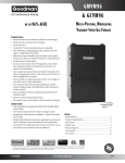
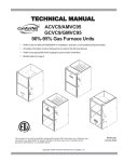
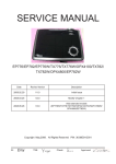
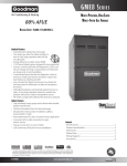
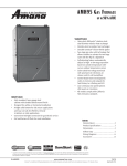
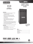
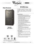
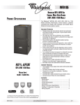
GMVC95 & GCVC95/9 GMVC95: up to 95% AFUE GCVC95: up to 95% AFUE GCVC9: up to 93% AFUE ComfortNet™-Compatible Multi-Position, Two-Stage Variable-Speed Gas Furnace Standard Features • Dual-diameter tubular heat exchanger • Two-stage gas valve operates with two-stage or single- stage thermostats • ComfortNet™ Communications System compatible • Efficient and quiet variable-speed ECM circulator motor gently ramps up or down according to heating or cooling demand • 120V Silicon Nitride igniter designed for long igniter life • Furnace control board with self-diagnostics, color-coded low-voltage terminals, and provisions for electronic air cleaner and 120-volt or 24-volt humidifiers • Low constant fan allows homeowner to activate very low speed to efficiently circulate air throughout the home. This setting costs as little as a 100-watt light bulb to operate. • Dual-certified for sealed combustion direct vent (2-pipe) or non-direct vent (1-pipe) applications • Quiet two-speed induced draft blower • All models comply with California NOx emissions standards Cabinet Features • Fully insulated, heavy-gauge steel cabinet with durable baked-enamel finish • Foil-faced insulation lines the heat exchanger • Easy-to-install top venting is standard; alternate flue/vent connections on some models • Designed for multi-position installation – GMVC95: upflow, horizontal left or right; GCVC95/9: downflow, horizontal left or right • Airtight solid bottom for side return applications and easy-cut tabs for effortless removal in bottom air inlet applications • Convenient left or right connection for gas/electric service • Coil and furnace fit flush for most installations Contents Nomenclature..................................................................... 2 Product Specifications........................................................ 3 Dimensions......................................................................... 4 Airflow Data........................................................................ 6 Wiring Diagrams............................................................... 10 Thermostats ..................................................................... 12 Accessories........................................................................12 * Complete warranty details available from your local dealer or at www.goodmanmfg.com. To receive the Lifetime Heat Exchanger Limited Warranty (good for as long as you own your home), 10-Year Unit Replacement Limited Warranty and 10-Year Parts Limited Warranty, online registration must be completed within 60 days of installation. Online registration is not required in California or Québec. SS-GMVC95 www.goodmanmfg.com 5/11 Supersedes 11/10 Product Specifications Nomenclature G M V C 95 070 4 C X A A 1 2 3 4 5,6 7,8,9 10 11 12 13 14 Brand G Goodman® Brand Revisions Major and minor revisions Airflow Direc5on C Downflow/Horizontal D Dedicated Downflow H High Airflow K Dedicated Upflow M Upflow/Horizontal NOx N X Cabinet Width A 14” B 17½” C 21” D 24½” Descrip5on/Motor V Two-‐Stage/Variable-‐speed H Two-‐Stage/MulR-‐speed S Single-‐Stage/MulR-‐speed E Two-‐Stage/High-‐Efficiency SystemType C ComfortNet™ CommunicaRng System Natural Gas Low NOx 3 1200 4 1600 Maximum CFM @ 0.5” ESP 5 2000 MBTU/h AFUE 95 95% 9 90%+ 8 80% 045: 45,000 070: 70,000 090: 90,000 115: 115,000 140: 140,000 Important EnergyStar Notice: EnergyStar ratings are dependent upon conditions beyond equipment installation. Proper sizing and installation of equipment is critical to achieve optimal performance. Split system air conditioners and heat pumps must be matched with appropriate coil components to meet EnergyStar criteria. Ask your contractor for details or visit www.energystar.gov. 2www.goodmanmfg.com SS-GMVC95 Product Specifications Specifications GMVC95 0453BX GMVC95 0704CX GMVC95 0905CX GMVC95 0905DX GMVC95 1155DX GCVC95 0714CX GCVC95 0915DX GCVC9 1155DX High Fire Input¹ 46,000 69,000 92,000 92,000 115,000 69,000 92,000 115,000 High Fire Output¹ 45,000 67,000 90,000 90,000 109,000 65,000 87,000 109,000 Low Fire Input¹ 32,000 48,000 64,000 64,000 80,000 48,000 64,000 80,000 Low Fire Output¹ 30,800 46,400 61,700 61,700 77,400 45,000 60,100 77,400 95 95 95 95 95 95 95 93 Tons AC @ 0.5” ESP 1.5 - 3.0 1.5 - 4.0 2.0 - 5.0 2.0 - 5.0 2.0 - 5.0 1.5 - 4.0 2.0 - 5.0 2.0 - 5.0 Temperature Rise Range (°F) 30 - 60 30 - 60 30 - 60 30 - 60 30 - 60 25-55 25-55 40-70 10” x 8” 10” x 10” 11” x 10” 11” x 10” 11” x 10” 10” x 10” 11” x 10” 11” x 10” ½ ¾ 1 1 1 ¾ 1 1 Heating Capacity AFUE² Circulator Blower Size (D x W) Horespower @ 1050 RPM Speed Variable Variable Vent Diameter³ 2” 2” 3” 3” 3” 2” 3” 3” No. of Burners 2 3 4 4 5 3 4 5 288 384 480 480 486 384 480 486 Min. Circuit Ampacity (amps)4 11.3 14.1 14.4 14.4 14.4 11.2 15.0 14.4 Max. Overcurrent Protection 15 amps 15 amps 15 amps 15 amps 15 amps 15 amps 15 amps 15 amps 121 145 160 160 170 139 165 160 Disposable Filter (in²) Electrical Data 5 Ship Weight (lbs) ¹ ² ³ 4 Natural Gas BTU/h DOE AFUE based upon Isolated Combustion System (ICS) Installer must supply one or two PVC pipes: one for combustion air (optional) and one for the flue outlet (required). Vent pipe must be either 2” or 3” in diameter, depending upon furnace input, number of elbows, length of run and installation (1 or 2 pipes). The optional Combustion Air Pipe is dependent on installation/code requirements and must be 2” or 3” diameter PVC. Minimum Circuit Ampacity = (1.25 x Circulator Blower Amps) + ID Blower amps. Wire size should be determined in accordance with National Electrical Codes. Extensive wire runs will require larger wire sizes. 5 Maximum Overcurrent Protection Device refers to maximum recommended fuse or circuit breaker size. May use fuses or HACR-type circuit breakers of the same size as noted. Notes • All furnaces are manufactured for use on 115 VAC, 60 Hz, single-phase electrical supply. • Gas Service Connection ½” FPT • Important: Size fuses and wires properly and make electrical connections in accordance with the National Electrical Code and/or all existing local codes. SS-GMVC95 www.goodmanmfg.com 3 Product Specifications GMVC95 Dimensions 28¾ ¾ ¾ ¾ 2½ 19⅞ 2¹/₁₆ 2¹¹/₁₆ 7⅜ 4⅛ 1¾ 30¼ 6⅛ 24⁹/₁₆ 27⅛ 1½ 2⅝ 21¼ 30¼ 2⅝ 19³/₁₆ 19³/₁₆ 1¾ 1⅝ 11¾ 16⅝ 11¾ 22 ¹/₁₆ FOLDED FLANGES FOLDED FLANGES 23 ⁹/₁₆ UNFOLDED FLANGES UNFOLDED FLANGES 1¾ D E FRONT VIEW LEFT SIDE VIEW Model 32¹³/₁₆ A B RIGHT SIDE VIEW C D E GMVC950453BX 17½” 16” 13⅛” 12⅛” 13⅝” GMVC950704CX 21” 19½” 16⅛” 16 17½” GMVC950905CX 21” 19½” 16⅛” 16 17½” GMVC950905DX 24½” 23” 20⅝” 19⅜” 20⅞” GMVC951155DX 24½” 23” 20⅝” 19⅜” 20⅞” Notes: • Installer must supply one or two PVC pipes: one for combustion air (optional) and one for the flue outlet (required). Vent pipe must be either 2” or 3” in diameter, depending upon furnace input, number of elbows, length of run and installation (1 or 2 pipes). The optional Combustion Air Pipe is dependent on installation/code requirements and must be 2” or 3” diameter PVC. • Line voltage wiring can enter through the right or left side of the furnace. Low-voltage wiring can enter through the right or left side of furnace. • Conversion kits for high-altitude natural gas operation are available. Contact your Goodman distributor or dealer for details. • Installer must supply following gas line fittings, according to which entrance is used: Left—Two 90º elbows, one close nipple, straight pipe Right—Straight pipe to reach gas valve • For bottom return: Failure to unfold flanges may reduce airflow by up to 18%. This could result in performance and noise issues. Minimum Clearances to Combustible Materials Position Sides Rear Front Bottom Flue Top Upflow 0” 0” 3” C 0” 1” Horizontal 6” 0” 3” C 0” 6” C = If placed on combustible floor, the floor MUST be wood ONLY. Notes • For servicing or cleaning, a 24” front clearance is required. • Unit connections (electrical, flue and drain) may necessitate greater clearances than the minimum clearances listed above. • In all cases, accessibility clearance must take precedence over clearances from the enclosure where accessibility clearances are greater. 4www.goodmanmfg.com SS-GMVC95 Product Specifications GCVC95/9 Dimensions FOLDED FLANGES FOLDED FLANGES UNFOLDED FLANGES UNFOLDED FLANGES Model A B C D E GCVC950714CX 21” 19½” 16⅛” 18” 19½” GCVC950915DX 24½” 23” 20⅝” 21½” 23” GCVC91155DX 24½” 23” 20⅝” 21½” 23” Notes: • Installer must supply one or two PVC pipes: one for combustion air (optional) and one for the flue outlet (required). Vent pipe must be either 2” or 3” in diameter, depending upon furnace input, number of elbows, length of run, and installation (1 or 2 pipes). The optional Combustion Air Pipe is dependent on installation/code requirements and must be 2” or 3” diameter PVC. • Line voltage wiring can enter through the right or left side of the furnace. Low-voltage wiring can enter through the right or left side of furnace. • Conversion kits for high-altitude natural gas operation are available. Contact your Goodman distributor or dealer for details. • Installer must supply following gas line fittings, according to which entrance is used: Left—Two 90º elbows, one close nipple, straight pipe Right—Straight pipe to reach gas valve • For bottom return: Failure to unfold flanges may reduce airflow by up to 18%. This could result in performance and noise issues. Minimum Clearances to Combustible Materials Position Sides Rear Front Bottom Flue Top Downflow 0” 0” 3” NC 0” 1” Horizontal 6” 0” 3” C 0” 6” C = If placed on combustible floor, the floor MUST be wood ONLY. NC = For installation on non-combustible floors only. A combustible floor sub-base must be used for installations on combustible flooring. Notes • For servicing or cleaning, a 24” front clearance is required. • Unit connections (electrical, flue and drain) may necessitate greater clearances than the minimum clearances listed above. • In all cases, accessibility clearance must take precedence over clearances from the enclosure where accessibility clearances are greater. SS-GMVC95 www.goodmanmfg.com 5 Product Specifications GMVC95 Airflow Data Cooling Speeds GMVC950453BX Tap A B C D High Stage Adjust CFM* Minus(-) Normal Plus (+) Minus(-) Normal Plus (+) Minus(-) Normal Plus (+) Minus(-) Normal Plus (+) 540 600 660 720 800 880 900 1000 1100 1080 1200 1320 Tap A B C D GMVC950704CX Low Stage Adjust CFM* Minus(-) Normal Plus (+) Minus(-) Normal Plus (+) Minus(-) Normal Plus (+) Minus(-) Normal Plus (+) 351 390 429 468 520 572 585 650 715 702 780 858 Tap A B C D High Stage Adjust CFM* Minus(-) Normal Plus (+) Minus(-) Normal Plus (+) Minus(-) Normal Plus (+) Minus(-) Normal Plus (+) 540 600 660 720 800 880 990 1100 1210 1286 1429 1572 GMVC950905CX Tap A B C D High Stage Adjust CFM* Minus(-) Normal Plus (+) Minus(-) Normal Plus (+) Minus(-) Normal Plus (+) Minus(-) Normal Plus (+) 729 810 891 990 1100 1210 1323 1470 1617 1629 1810 1991 Tap A B C D Tap A B C D Low Stage Adjust CFM* Minus(-) Normal Plus (+) Minus(-) Normal Plus (+) Minus(-) Normal Plus (+) Minus(-) Normal Plus (+) 351 390 429 468 520 572 644 715 787 836 929 1022 Low Stage Adjust CFM* Minus(-) Normal Plus (+) Minus(-) Normal Plus (+) Minus(-) Normal Plus (+) Minus(-) Normal Plus (+) 468 520 572 644 715 787 819 910 1001 1053 1170 1287 GMVC950905DX Low Stage Adjust CFM* Minus(-) Normal Plus (+) Minus(-) Normal Plus (+) Minus(-) Normal Plus (+) Minus(-) Normal Plus (+) 495 550 605 693 770 847 900 1000 1100 1125 1250 1375 Low Stage Adjust CFM* Minus(-) Normal Plus (+) Minus(-) Normal Plus (+) Minus(-) Normal Plus (+) Minus(-) Normal Plus (+) 468 520 572 644 715 787 819 910 1001 1053 1170 1287 Tap A B C D High Stage Adjust CFM* Minus(-) Normal Plus (+) Minus(-) Normal Plus (+) Minus(-) Normal Plus (+) Minus(-) Normal Plus (+) 720 800 880 900 1000 1100 1260 1400 1540 1620 1800 1980 Tap A B C D GMVC951155DX Tap A B C D High Stage Adjust CFM* Minus(-) Normal Plus (+) Minus(-) Normal Plus (+) Minus(-) Normal Plus (+) Minus(-) Normal Plus (+) 720 800 880 990 1100 1210 1260 1400 1540 1620 1800 1980 Tap A B C D * @ .1" - .8" w.c. ESP Notes: • All furnaces ship as high speed for cooling. Installer must adjust blower speed as needed. • For most jobs, about 400 CFM per ton when cooling is desirable. • Do not operate above .5” w.c. ESP in heating mode. Operating CFM between .5” and .8” w.c. is tabulated for cooling purposes only. 6www.goodmanmfg.com SS-GMVC95 Product Specifications GMVC95 Airflow Data (cont.) Heating Speeds GMVC950453BX (Rise Range: 30 - 60°F) Tap A B C D GMVC950704CX Rise Range: 30 - 60°F) Adjust Low-Stage CFM * High-Stage CFM * Rise (°F) Minus(-) Normal Plus (+) Minus(-) Normal Plus (+) Minus(-) Normal Plus (+) Minus(-) Normal Plus (+) 495 550 605 540 600 660 585 650 715 630 700 770 713 792 871 778 864 950 842 936 1,030 907 1,008 1,109 57 41 46 52 47 43 48 43 39 45 40 36 Tap A B C D Adjust Low-Stage CFM * High-Stage CFM * Rise (°F) Minus(-) Normal Plus (+) Minus(-) Normal Plus (+) Minus(-) Normal Plus (+) Minus(-) Normal Plus (+) 756 840 924 828 920 1,012 900 1,000 1,100 972 1,080 1,188 1,089 1,210 1,331 1,192 1,325 1,457 1,296 1,440 1,584 1,400 1,555 1,711 56 50 46 51 46 42 47 42 38 43 39 35 GMVC950905CX (Rise Range: 30 - 60°F) Tap A B C D GMVC950905DX (Rise Range: 30 - 60°F) Adjust Low-Stage CFM * High-Stage CFM * Rise (°F) Minus(-) Normal Plus (+) Minus(-) Normal Plus (+) Minus(-) Normal Plus (+) Minus(-) Normal Plus (+) 945 1,050 1,155 1,008 1,120 1,232 1,080 1,200 1,320 1,125 1,250 1,375 1,341 1,490 1,639 1,413 1,570 1,727 1,521 1,690 1,859 1,602 1,780 1,958 60 54 49 57 51 47 53 48 43 50 45 41 Tap A B C D Adjust Low-Stage CFM * High-Stage CFM * Rise (°F) Minus(-) Normal Plus (+) Minus(-) Normal Plus (+) Minus(-) Normal Plus (+) Minus(-) Normal Plus (+) 1,013 1,125 1,238 1,076 1,195 1,315 1,139 1,265 1,392 1,202 1,335 1,469 1,458 1,620 1,782 1,549 1,721 1,893 1,640 1,822 2,004 1,730 1,922 2,114 55 50 45 52 47 43 49 44 40 47 42 38 GMVC951155DX (Rise Range: 35 - 65°F) Tap A B C D Adjust Low-Stage CFM * High-Stage CFM * Rise (°F) Minus(-) Normal Plus (+) Minus(-) Normal Plus (+) Minus(-) Normal Plus (+) Minus(-) Normal Plus (+) 1,107 1,230 1,353 1,139 1,265 1,392 1,170 1,300 1,430 1,202 1,335 1,469 1,594 1,771 1,948 1,639 1,822 2,004 1,685 1,872 2,059 1,730 1,922 2,115 63 57 52 62 56 50 60 54 49 58 53 48 * @ .1" - .5" w.c. ESP Notes • All furnaces ship as high speed for cooling. Installer must adjust blower speed as needed. • For most jobs, about 400 CFM per ton when cooling is desirable. • Do not operate above .5” w.c. ESP in heating mode. Operating CFM between .5” and .8” w.c. is tabulated for cooling purposes only. SS-GMVC95 www.goodmanmfg.com 7 Product Specifications GCVC95 Airflow Data GCVC950714CX Cooling Speeds High Stage Tap Adjust Minus A Normal B C D GCVC950714CX Heating Speeds (Rise Range: 25 - 55°F) Low Stage CFM* Tap Adjust 594 Minus 660 A Normal High Stage CFM* Tap Adjust CFM* 324 Minus 1107 360 A Normal 1230 Low Stage Rise Tap Adjust CFM* Rise 55 Minus 783 77 49 A Normal 870 69 Plus 726 Plus 396 Plus 1353 45 Plus 957 63 Minus 747 Minus 468 Minus 1215 50 Minus 855 71 Normal 830 Normal 520 Normal 1350 45 Normal 950 64 Plus 913 Plus 572 Plus 1485 41 Plus 1045 58 Minus 1017 Minus 702 Minus 1323 46 Minus 936 65 Normal 1130 Normal 780 Normal 1470 41 Normal 1040 58 Plus 1243 Plus 858 Plus 1617 37 Plus 1144 53 Minus 1314 Minus 864 Minus 1440 42 Minus 1017 59 Normal 1460 Normal 1600 38 Normal 1130 53 Plus 1606 Plus 1760 34 Plus 1243 49 B C D Normal 960 Plus 1056 B C D B C D * @ .1" - .5" w.c. ESP GCVC950915DX Cooling Speeds High Stage Tap A B C D GCVC950915DX Heating Speeds (Rise Range: 25 - 55°F) Low Stage Adjust CFM* Minus 729 Normal 810 Plus 891 Minus 999 Normal 1110 Plus 1221 Minus 1287 Normal 1430 Plus 1573 Minus 1674 Normal 1860 Plus 2046 Tap A B C D High Stage Adjust CFM* Minus 504 Normal 560 Plus 616 Minus 666 Normal 740 Plus 814 Minus 828 Normal 920 Plus 1012 Minus 1071 Normal 1190 Plus 1309 Tap A B C D Low Stage Adjust CFM* Rise Minus 1458 55 Normal 1620 50 Plus 1782 45 Minus 1575 51 Normal 1750 46 Plus 1925 42 Minus 1674 48 Normal 1860 43 Plus 2046 39 Minus 1773 45 Normal 1970 41 Plus 2167 37 Tap A B C D Adjust CFM* Rise Minus 1008 80 Normal 1120 72 Plus 1232 65 73 Minus 1098 Normal 1220 66 Plus 1342 60 Minus 1152 70 Normal 1280 63 Plus 1408 57 Minus 1206 67 Normal 1340 60 Plus 1474 55 * @ .1" - .5" w.c. ESP Notes • All furnaces ship as high speed for cooling. Installer must adjust blower speed as needed. • For most jobs, about 400 CFM per ton when cooling is desirable. • Do not operate above .5” w.c. ESP in heating mode. Operating CFM between .5” and .8” w.c. is tabulated for cooling purposes only. 8www.goodmanmfg.com SS-GMVC95 Product Specifications GCVC9 Airflow Data GCVC91155DX Cooling Speeds High Stage Tap A B C D Adjust GCVC91155DX Heating Speeds (Rise Range: 40 - 70°F) Low Stage CFM* Minus(-) 705 Normal 783 Plus (+) 861 Minus(-) 982 Normal 1091 Tap Adjust High Stage CFM* Minus(-) 457 Normal 508 Plus (+) 559 A Minus(-) 621 Normal 690 B Tap A B Adjust CFM* Low Stage Rise Minus(-) 1583 63 Normal 1759 56 Plus (+) 1935 51 Minus(-) 1612 61 Normal 1791 55 Tap A B Adjust CFM* Rise Minus(-) 1093 63 Normal 1214 56 Plus (+) 1335 51 Minus(-) 1106 61 Normal 1229 55 Plus (+) 1200 Plus (+) 759 Plus (+) 1970 50 Plus (+) 1352 50 Minus(-) 1265 Minus(-) 815 Minus(-) 1654 60 Minus(-) 1166 60 Normal 1406 Normal 906 Normal 1838 54 Normal 1296 54 C C C Plus (+) 1547 Plus (+) 997 Plus (+) 2022 49 Plus (+) 1426 49 Minus(-) 1628 Minus(-) 1049 Minus(-) 1690 59 Minus(-) 1172 59 Normal 1809 Normal 1165 Normal 1878 53 Normal 1302 53 Plus (+) 1990 Plus (+) 1282 Plus (+) 2066 48 Plus (+) 1432 48 D D D * @ .1" - .5" w.c. ESP Notes • All furnaces ship as high speed for cooling. Installer must adjust blower speed as needed. • For most jobs, about 400 CFM per ton when cooling is desirable. • Do not operate above .5” w.c. ESP in heating mode. Operating CFM between .5” and .8” w.c. is tabulated for cooling purposes only. Continuous Fan Speeds Maximum CFM Continuous Fan Speed¹ GMVC950453BX 1400 420 GMVC950704CX 1760 530 GMVC950905CX 2200 660 GMVC950905DX 2200 660 GMVC951155DX 2200 660 GCVC950704CX 1760 530 GCVC950905DX 2200 660 GCVC91155DX 2200 660 Model ¹ Continuous fan speed is 30% of furnace maximum CFM Standard Altitude Installations Kit Orifice Manifold Pressure High Stage Low Stage Pressure Switch Change Gas Altitude Natural 0-7000 Changeover None #43 3.5” W.C. 1.9” W.C. None Propane 0-7000 LPM-03B & LPM-05 #55 10.0: W.C. 6.0” W.C. None • For installation in Canada, gas furnaces are certified only to 4,500 ft. • For GCVA installations above 7,000 ft., please refer to your Amana distributor for required kit(s). SS-GMVC95 www.goodmanmfg.com 9 Wiring is subject to change. Always refer to the wiring diagram or the unit for the most up-to-date wiring. ⚠ Warning High Voltage: Disconnect all power before servicing or installing this unit. Multiple power sources may be present. Failure to do so may cause property damage, personal injury, or death. ⚡ Product Specifications GMVC95/GCVC95/9 Wiring Diagram with Honeywell Valve 10www.goodmanmfg.com SS-GMVC95 Product Specifications GMVC95/GCVC9 Wiring Diagram with White-Rodgers Valve TO 115 VAC/ 1 Ø /60 HZ POW ER SUPPLY W ITH OVERCURRENT PROTECTION DEVICE GND NO GY FRONT COVER PRESSURE SWITCH PK OR BR AUTO RESET PRIMARY LIM IT CONTROL INDUCED DRAFT BLOW ER GND BR BR 2 1 6 5 4 9 8 7 OR 12 11 10 PK UNUSED DEHUM 15 14 13 HEAT PU YL DELAY 3 FUSE 3 A GY BR R OR 24 VAC COOL 5 LINE 40 VA TRANSFORMER BK FS NEUTRAL 24V HUM. BL WH GY BK 4 3 5 4 3 2 1 1 2 BK BK GR PK GND NOTES: TH (4) 24 VAC MANUAL RESET AUXILIARY LIMIT CONTROLS INDUCTOR COIL 70kBTU,90kBTU, 115kBTU MODELS ONLY COLOR CODES: PK PINK BR BROWN WH WHITE BL BLUE GY GRAY RD RED YL YELLOW OR ORANGE PU PURPLE GN GREEN BK BLACK ⚡ AUTO RESET PRIMARY LIMIT CONTROL LOW FIRE PRESS. SWITCH 24V HUM. PS1 (2) C NO W2 Y2 TO MICRO PS 2 ( 12) NO C HIGH FIRE PRESS. SWTICH MANUAL RESET ROLLOUT LIMIT CONTROLS G HLI (1) MVL (13) MVH (14) C NO C FRONT COVER PRESS. SWITCH MVC (8) GND TR (11) GND (4) + VDC (1) RX (2) TO MICRO TX (3) INDOOR AIR CIRCULATOR BLWR INTEGRATED CONTROL MODULE HUMIDIFIER LOW VOLTAGE (24V) EQUIPMENT GND LOW VOLTAGE FIELD HI VOLTAGE (115V) HI VOLTAGE FIELD JUNCTION TERMINAL INTERNAL TO INTEGRATED CONTROL PLUG CONNECTION PM HI C GND (5) BK BLOWER COMPARTMENT DOOR SWITCH (OPEN WHEN DOOR OPEN) NEUTRAL 40 VA TRANSFORMER PSO (7) W1 TO R 1. SET HEAT ANTICIPATOR ON ROOM THERMOSTAT AT 0.7 AMPS. 2. MANUFACTURER'S SPECIFIED REPLACEMENT PARTS MUST BE USED WHEN SERVICING. 3. IF ANY OF THE ORIGINAL WIRE AS SUPPLIED WITH THE FURNACE MUST BE REPLACED, IT MUST BE REPLACED WITH WIRING MATERIAL HAVING A TEMPERATURE RATING OF AT LEAST 105°C. USE COPPER CONDUCTORS ONLY. 4. UNIT MUST BE PERMANENTLY GROUNDED AND CONFORM TO N.E.C. AND LOCAL CODES. 5. TO RECALL THE LAST 6 FAULTS, MOST RECENT TO LEAST RECENT, DEPRESS SWITCH FOR MORE THAN 2 SECONDS WHILE IN STANDBY (NO THERMOSTAT INPUTS) SS-GMVC95 WH BK WH CIRCULATOR BLOWER 0140F00530 Y1 DEHUM RD ECM MTR HARNESS 115 VAC HLO (10) O HUM WH NEUTRAL HOT SURFACE IGNITER TO +VDC EAC WH 4 NEUTRAL HUMIDIFIER IGN FLAME SENSOR GY 5 CIRCUIT CONNECTOR 2 HUM LINE 115 VAC 1 NEUTRAL ID BLWR IND LO FS ADJUST BL NEUTRAL ELECTRONIC AIR CLEANER IND HI OR 24V THERMOSTAT CONNECTIONS 4 CIRCUIT MOTOR CONNECTOR DIP SWITCHES TWO-STAGE INTEGRATED CONTROL MODULE RD HEAT OFF DELAY EAC OR 3 2ND STG DLY T-STAT NEUTRAL INTEGRATED CONTROL MODULE YL 2 24 V 3A 1 G C BK WH 4 R Y1 W2 W1 Y2 RD DEHUM O WH 2 3 FUSE GY PK 24 V THERMOSTAT CONNECTIONS 1 GND YL MANUAL RESET AUXILIARY LIMIT CONTROL SEE NOTE 5 INDOOR AIR CIRCULATOR BLWR LINE PU DIAGNOSTIC LED'S JUNCTION BOX INDUCTOR COIL 70kBTU,90kBTU, 115kBTU MODELS ONLY INTEGRATED CONTROL MODULE BLOW ER COMPARTM ENT DOOR SWITCH PU 1 BURNER COMPARTM ENT N DISCONNECT GN 2 OR PU WH RD BK 3 BL BL CHASSIS GROUND M ANUAL RESET ROLLOUT LIMIT CONTROLS (SINGLE CONTROL ON 45 kBTU) GND L WARNING: DISCONNECT POWER BEFORE SERVICING. WIRING TO UNIT MUST BE PROPERLY POLARIZED AND GROUNDED. GAS VALVE High Voltage: Disconnect all power before servicing or installing this unit. Multiple power sources may be present. Failure to do so may cause property damage, personal injury, or death. FLAME SENSOR C GY 1 TO 115VAC/ 1 Ø /60 HZ POWER SUPPLY WITH OVERCURRENT PROTECTION DEVICE ⚠ Warning WH PM WH DISCONNECT BR 2 WARNING:DISCONNECT POWER BEFORE SERVICING. WIRING TO UNIT MUST BE PROPERLY POLARIZED AND GROUNDED. N NO OR PU 3 C C NO YL RD HI C HIGH FIRE PRESSURE SW ITCH L BK Wiring is subject to change. Always refer to the wiring diagram or the unit for the most up-to-date wiring. OR HOT LOW FIRE SURFACE PRESSUR IGNITER E SWITCH 2 CIRCUIT 2 1 CONNECTOR TW O STAGE GAS VALVE 24V HUM. JUNCTION BOX ID BLOW ER TW O-STAGE PRESSURE SW ITCH ASSEMBLY FIELD GND FIELD SPLICE SWITCH (TEMP.) IGNITER SWITCH (PRESS.) OVERCURRENT PROT. DEVICE REV. B www.goodmanmfg.com 11 Product Specifications Thermostats GTS1175-2 GTS3275-2 GTS 4275-2 Touch-Screen Digital Thermostats (See Amana Thermostat specification sheets for details.) G2111-2 G3272-2 G3273-2 Touch-Screen Digital Thermostats (See Amana Thermostat specification sheets for details.) G1100-2 G2100-2 G1152-2 G2152-2 Programmable and Non-programmable Digital Thermostats (See Amana Thermostat specification sheets for details.) Accessories GMVC95 0453BX GMVC95 0704CX GMVC95 0905C/DX GMVC95 1155DX GCVC95 0704CX GCVC95 0905DX GCVC9 1155DX LP Conversion Kit * (Springs & Orifice) 1 1 1 1 1 1 1 1 Model LPM-05 Description LPM-06 LP Conversion Kit ** (Springs & Orifice) 1 1 1 1 1 1 GSAS Electronic Air Cleaners (-10, -11, -12 or -18) √ √ √ √ √ √ √ GMU Media Air Cleaners (1620, 2020, 1625 or 2025) √ √ √ √ √ √ √ DEHUM1 Dehumidistat √ √ √ √ √ √ √ HAPS28 High-Altitude Pressure Switch Kit 2 2 --- --- --- --- ----- HAPS29 High-Altitude Pressure Switch Kit --- --- --- 2 --- --- HAPS 31 High-Altitude Pressure Switch Kit --- --- --- --- --- --- 2 HALP11 High-Altitude Propane Gas Kit 2 2 2 --- --- --- --- --- --- 2 3 --- --- --- HALP 13 High-Altitude Propane Gas Kit --- --- HANG 13 High-Altitude Natural Gas Kit 3 3 HANG 14 High-Altitude Natural Gas Kit 4 4 4 --- --- --- HANG 16 High-Altitude Natural Gas Kit --- --- --- --- --- --- 2 EFR01 External Filter Rack √ √ √ √ √ √ √ --- --- DCVK-20 Horizontal/Vertical Concentric Vent Kit (2”) √ √ √ --- √ --- DCVK-30 Horizontal/Vertical Concentric Vent Kit (3”) √ √ √ √ √ √ √ CFB21 Downflow Floor Base --- --- --- --- √ --- --- CFB24 Downflow Floor Base --- --- --- --- --- √ √ 017K00000S Flush-mount vent kit √ √ √ √ √ √ √ * White-Rodgers gas valve ** Honeywell or White-Rodgers gas valve 2 7,001’ to 11,000’ 1 All Models up to 7,000’ 3 7,001’ to 9,000’ 4 9,001’ to 11,000’ Note: All installations above 7,000’ require a pressure switch change. For installation in Canada, gas furnaces are certified only to 4,500’. Goodman Manufacturing Company, L.P., reserves the right to discontinue, or change at any time, specifications or designs without notice or without incurring obligations. © 2011 • Goodman Manufacturing Company, L.P. • Houston, Texas • Printed in the USA. 12www.goodmanmfg.com SS-GMVC95