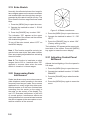
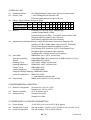
1
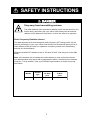
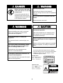
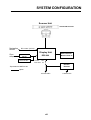
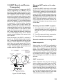
C
Yo u r L o c a l A g e n t/D e a le r
9-52, A shihara-cho,
N ishinom iya, Japan
Te l e p h o n e :
Te l e f a x :
0 7 9 8 -6 5 -2 111
0798-65-4200
A ll rig h ts re s e rv e d .
Printed in Japan
PUB. No. OM E-34810
(YO SH )
M O DEL 1761 M ARK-3
FIRST
EDITIO N
D
:
:
AUG. 1998
JUL. 10, 2001
SAFETY INSTRUCTIONS
DANGER
Stay away from transmitting antenna.
The radar antenna emits microwave radiation which can be harmful to the
human body, particularly the eyes. Never look directly into the antenna
radiator from a distance of less than 1 m when the radar is in operation.
Radio Frequency Radiation Hazard
The radar antenna emits electromagnetic radio frequency (RF) energy which can be
harmful, particularly to your eyes. Never look directly into the antenna aperture from a
close distance while the radar is in operation or expose yourself to the transmitting
antenna at a close distance.
Distances at which RF radiation levels of 100 and 10 W/m2 exist are given in the table
below.
Note: If the antenna unit is installed at a close distance in front of the wheel house,
your administration may require halt of transmission within a certain sector of antenna
revolution. This is possible—Ask your FURUNO representative or dealer to provide
this feature.
MODEL
Radiator
type
Distance to
100 W/m2
point
Distance to
10 W/m2
point
1761 MK-3
XN10A
0.2 m
Worst case 3.0 m
i
DANGER
WARNING
Use the proper fuse.
Before turning on the radar
make sure no one is near the
scanner unit.
Fuse rating is shown in the chapter 5.
Use of a wrong fuse can result in equipment
damage
Prevent the potential risk of
someone begin struck by the
rotating antenna and exposure
to RF radiation hazard.
Do not operate the equipment with wet
hands.
Electrical shock can result.
WARNING
CAUTION
Do not open the equipment.
Do not use the equipment for other than
its intended purpose.
Improper handling can result in electrical
shock. Only qualified personnel shold
work inside the equipment.
Use of the equipment as a stepping stool,
for example, can result in personal injury
or equipment damage.
Do not disassemble or modify the
equipment.
No one navigation device should ever be
solely replied upon for the navigation of
a vessel.
Fire electrical shock or serious injury can
result.
Always confirm position against all available
aids to navigation, for safety of vessel and
crew.
Turn off the power immediately if water
leaks into the equipment or the equipment is emitting smoke or fire.
Continued use of the equipment can
cause fire or electrical shock.
Two warning labels are attached to the display
unit and scanner unit. Do not remove these labels.
If labels are peeling off or are illegible, contact
a FURUNO agent or dealer.
Do not place liquid-filled containers on
the top of the equipment.
<Display Unit>
Fire or electrical shock can result if a liquid
spills into the equipment.
Name: Warning Label (1)
Type: 86-003-1011-0
Code no.: 100-236-230
<Scanner Unit>
Name: Radiation Warning
Label
Type: 03-142-3201-0
Code no.: 100-266-890
ii
WARNING
To avoid electrical shock, do not
remove cover. No user-serviceable
parts inside.
WARNING
Radiation hazard. Only qualified
personnel should work inside scanner.
Confirm that TX has stopped before
opening scanner.
FOREWORD
Features
Congratulations on your choice of the
FURUNO MODEL 1761 MARK-3 Marine Radar. We are confident you will see why the
FURUNO name has become synonymous
with quality and reliability.
Your radar has a large variety of functions,
all contained in a remarkably small cabinet.
The main features of the MODEL 1761
MARK-3 are:
For over 50 years FURUNO Electric Company has enjoyed an enviable reputation for
innovative and dependable marine electronics equipment. This dedication to excellence
is furthered by our extensive global network
of agents and dealers.
¡ Traditional FURUNO reliability and quality in a compact, lightweight and low-cost
radar.
¡ Durable brushless antenna motor.
¡ On-screen alphanumeric readout of all operational information.
Your radar is designed and constructed to
meet the rigorous demands of the marine environment. However, no machine can perform its intended function unless properly
installed and maintained. Please carefully
read and follow the recommended procedures for installation, operation and maintenance.
¡ Standard features include EBL (Electronic
Bearing Line), VRM (Variable Range
Marker), Guard Alarm, Display Off Center, and Echo Trail.
¡ Watchman feature periodically transmits
the radar to check for radar targets which
may be entering the alarm zone.
While this unit can be installed by the purchaser, any purchaser who has doubts about
his or her technical abilities may wish to have
the unit installed by a FURUNO representative or other qualified technician. The importance of a through installation can not be
overemphasized.
¡ Ship’s position in latitude and longitude,
range and bearing to a waypoint, and
ship’s speed/heading/course can be
shown in the bottom text area. (Requires
a navigation aid which can output such
data in IEC 61162 format.)
¡ Zoom feature provided.
We would appreciate hearing from you, the
end-user, about whether we are achieving
our purposes.
Thank you for considering and purchasing
FURUNO equipment.
iii
TABLE OF CONTENTS
2.21 Adjusting Control Panel Brilliance ......
..................................................... 2-8
2.22 Selecting Ranges ......................... 2-9
2.23 EBL/Cursor Bearing Reference ... 2-9
2.24 Guard Alarm ................................. 2-9
2.25 Watchman .................................. 2-10
2.26 Plotting ........................................ 2-11
2.27 Navigation Data Display .............. 2-11
FOREWORD .............................. iii
MENU TREE ............................... v
TABLE OF CONTENTS BY
INDICATION, MARKER ............. vi
SYSTEM CONFIGURATION..... vii
3. FALSE ECHOES
1. PRINCIPLE OF OPERATION
3.1 Multiple Echoes ..............................
3.2 Side-lobe Echoes ...........................
3.3 Indirect Echoes ..............................
3.4 Blind and Shadow Sectors .............
3.5 SART (Search and Rescue
Transponder) .................................
1.1 What is Radar? .............................. 1-1
1.2 How Ships Determined Position Before
Radar ............................................. 1-1
1.3 How Radar Determines Range ...... 1-1
1.4 How Radar Determines Bearing .... 1-1
1.5 Radar Wave Speed and Antenna
Rotation Speed .............................. 1-1
1.6 The Radar Display ......................... 1-1
3-1
3-1
3-2
3-2
3-3
4. MAINTENANCE & TROUBLESHOOTING
4.1 Preventive Maintenance ................
4.2 Replacing the Fuse ........................
4.3 Troubleshooting ..............................
4.4 Life Expectancy of Magnetron .......
2. OPERATION
2.1 Control Description ......................... 2-1
2.2 Turning the Radar On/Off ............... 2-2
2.3 Transmitting .................................... 2-2
2.4 Stand-by ......................................... 2-2
2.5 Selecting the Range ....................... 2-2
2.6 Adjusting Picture Brilliance ............. 2-2
2.7 Adjusting Receiver Sensitivity ........ 2-2
2.8 Adjusting the A/C SEA Control
(reducing sea clutter) ..................... 2-3
2.9 Adjusting the A/C RAIN Control
(reducing rain clutter) ..................... 2-4
2.10 Adjusting FTC ............................... 2-4
2.11 Turning the Radar Receiver ......... 2-4
2.12 Erasing the Heading Marker ........ 2-4
2.13 Select the Cursor Data Display .... 2-5
2.14 Turning the Range Ring On/Off ... 2-5
2.15 Measuring the Range ................... 2-5
2.16 Measuring the Bearing ................. 2-5
2.17 Shifting and Zooming the Display ......
..................................................... 2-6
2.18 Menu Operation ........................... 2-7
2.19 Echo Stretch ................................. 2-8
2.20 Suppressing Radar Interference .. 2-8
4-1
4-1
4-2
4-3
SPECIFICATIONS ................ SP-1
INDEX .....................................IN-1
iv
MENU TREE
MENU KEY
1. ECHO STRETCH (ON, OFF)
2. I. REJECT (OFF, ON)
3. PANEL DIMMER (0, 1, 2, 3, 4)
4. PLOT INTVL (CONT, 30S, 1M, 3M, 6M)
5. PLOT BRILL (LOW, @HIGH)
6. RANGE (NM) set with (RING)
(1/4, 1/2, 3/4, 1, 1.5, 2, 3, 4, 6, 8, 12, 16, 24, 48)
7. WATCHMAN (OFF, 5M, 10M, 20M)
8. NAV DATA (ON, OFF)
9. EBL/+CURSOR (TRUE, REL)
v
TABLE OF CONTENTS BY
INDICATION, MARKER
Elapsed time (P.2-11)
Plotting interval (P.2-11)
Plotting (P.2-11)
Tuning indicator (P.2-11)
MAG (or GYRO) BEARING (option)
Echo stretch (P.2-8)
Guard alarm (P.3-4)
Heading marker (P.2-4)
Range (P.2-2)
Range ring interval (P.2-2)
Shift (or Zoom) (P.2-6)
12 NM
3.0 NM
SHIFT
MAG 115.0 ¡
PLOT
WATCHMAN
3M
18:25 ES
*GUARD
FTC
IR
FTC (P.2-4)
Interference rejector (P.2-8)
Watchman (P.2-10)
EBL (P.2-6)
Guard zone (P.2-9)
Cursor (P.2-5, 6)
EBL1 bearing (P.2-6)
Range ring (P.2-3, 2-5)
EBL
45.6 ¡ R
315.1¡ R
9.05 NM
Cursor data(P.2-5)
Bearing /Range or
Latitude/Longitude
vi
VRM
2.62 NM
VRM range (P.2-5)
SYSTEM CONFIGURATION
Scanner Unit
XN10A-RSB-0070-065
Navigation
device
IEC 61162* (In/Out)
Display Unit
Gyrocompass
Gyro Converter
AD-100
Intergrated Heading
Sensor PG-1000
RDP-099
External Alarm
Buzzer OP03-21
12 VDC: 10A
24/32 VDC: 5A
Rectifier
RU-3423
*Equivalent to NMEA 0183
Option
12/24/32 VDC
vii
115/230 VAC
1. PRINCIPLE OF OPERATION
1.1 What is Radar?
The term “RADAR” is an acronym meaning
RAdio Detection And Ranging. Although the
basic principles of radar were developed during World War II, echoes as an aid to navigation is not a new development.
1.2 How Ships Determined
Position Before Radar
Before the invention of radar, when running
in fog near a rugged shoreline, ships would
sound a short blast on their whistles, fire a
shot, or strike a bell. The time between the
origination of the sound and the returning of
the echo indicated how far the ship was from
the cliffs or the shore. The direction from
which the echo was heard indicated the relative bearing of the shore.
1.3 How Radar Determines
Range
Radar determines the distance to the target
by calculating the time difference between the
transmission of a radar signal and the reception of the reflected echo. It is a known fact
that radar waves travel at a nearly constant
speed of 162,000 nautical miles per second.
Therefore the time required for a transmitted
signal to travel to the target and return as an
echo to the source is a measure of the distance to the target. Note that the echo makes
a complete round trip, but only half the time
of travel is needed to determine the one-way
distance to the target. This radar automatically takes this into account in making the
range calculation.
1.4 How Radar Determines
Bearing
The bearing to a target found by the radar is
determined by the direction in which the radar scanner antenna is pointing when it emits
an electronic pulse and then receives a returning echo. Each time the scanner rotates
pulses are transmitted in the full 360 degree
circle, each pulse at a slightly different bearing from the previous one. Therefore, if one
knows the direction in which the signal is sent
out, one knows the direction from which the
echo must return.
1.5 Radar Wave Speed and
Scanner Rotation Speed
Note that the speed of the radar waves out
to the target and back again as echoes is
extremely fast compared to the speed of rotation of the scanner. By the time radar echoes have returned to the scanner, the amount
of scanner rotation after initial transmission
of the radar pulse is extremely small.
1.6 The Radar Display
The range and bearing of a target is displayed
on what is called a Plan Position Indicator
(PPI). This display is essentially a polar diagram, with the transmitting ship’s position at
the center. Images of target echoes are received and displayed at their relative bearings, and at their distance from the PPI center.
With a continuous display of the images of
targets, the motion of the transmitting ship is
also displayed.
1-1
Heading marker
Targets
A
D
B
A
D
B
C
C
Own ship
in center
Own ship
(radar)
(A) Bird's eye view of situation
(B) Radar picture of (A)
Figure 1-1 How radar works
1-2
Range and bearing
of a target, relative
to own ship, are
readable on the PPI.
2. OPERATION
2.1 Control Description
Turns power on.
Press together with [STBY/TX] key
to turn power off.
GAIN
Alternates between stand-by and
transmit.
Lights (in green) to show the
radar is in the "echonomy
(stand-by)" mode.
POWER
PUSH/HM OFF
OFF
A/C SEA
STBY
TX
ECONOMY
Adjusts the brightness of the screen.
Selects radar range.
The "+" and "-" touchpads select a
higher and lower range, respectively.
Selets items during the menu display.
Shifts the display; turns the zoom
function on, and restores normal
picture, in that order.
Turns the Electronic Bearing
Line (EBL) on and off.
PUSH/PLOT
A/C RAIN
BRILL
(Control) Adjusts sensitivity of radar
receiver.
(Switch) 1. Temporarily erases heading
marker.
2. Change + cursor data from
R/B to L/L and vice versa.
(Control) Reduces sea clutter caused
by waves.
(Switch) Turns on/off the radar
target plotting
PUSH/FTC
RANGE
(Control) Reduces rain clutters.
(Switch) Suppresses heavy
precipitation.
SHIFT
ZOOM
RING
Turns the fixed range rings on and off.
EBL
VRM
Turns the Variable Range Marker
(VRM) on and off.
GUARD
MENU
Turns the menu display on and off.
Turns on and off the guard zone alarm.
Trackball
(1) Shifts cursor, EBL and VRM.
(2) Sets guard zone.
(3) Selects items and options on
menu.
(4) Shifts origin of EBL and VRM.
Figure 2-1 Control panel
2-1
2.2 Turning the Radar On/Off
2.5
After confirming there are no crew near the
scanner unit, press the [POWER] key to turn
on the power.
The range selected automatically determines
the fixed range ring interval, the number of
fixed range rings, pulselength, and pulse repetition rate, for optimal detection in short to
long ranges. The range and ring interval appear at the top left corner of the display.
The front panel will light up. The magnetron
takes about two minutes and thirty seconds
to warm up before the radar can be operated. The time remaining for warm up of the
magnetron appears at the center of the display, counting down from 2:29 to 0:01.
To turn off the radar, press the [POWER] and
[TX] key together.
Selecting the Range
Selecting the range
Press the [- RANGE +] key. The range and
range ring interval appear at the top left corner on the display.
Tips for selecting the range
2.3 Transmitting
After the power is turned on and the magnetron has warmed up, the message “ST-BY”
(Stand-By) appears at the center of the display, showing the radar is ready to transmit.
However, no targets will appear on the screen
until the radar is transmitting by pressing the
[TX] key (TX is short for “transmit). In standby the radar is available for use at anytime but no radar waves are being transmit.
2.4
Stand-by
When you won’t be using the radar for an
extended period, but you want to keep it in a
state of readiness, place it in stand-by by
pressing the [TX] key. The display shows
“STBY,” (default setting) or goes into the
economy mode. (You can select stand-by
condition on the menu. )
Economy mode
The CRT can be set to automatically turn itself off when in stand-by, to reduce power
consumption. This feature is called the
“economy mode”. When the economy mode
is on, the “ECONOMY” indication under the
[TX] key lights.
2-2
•
When navigating in or around crowded
harbors, select a short range to watch for
possible collision situation.
•
If you select a lower range while on open
water, increase the range occasionally to
watch for vessels that may be heading
your way.
2.6
Adjusting Picture
Brilliance
The [BRILL] key adjusts the brilliance of the
radar picture in eight levels.
Press the [BRILL] key to set the brilliance
level.
2.7
Adjusting Receiver
Sensitivity
The [GAIN] control adjusts the sensitivity of
the receiver. It works in precisely the same
manner as the volume control of a broadcast
receiver, amplifying the signals received.
The proper setting is such that the background noise is just visible on the screen. If
you set up noise is just visible on the screen.
If you set up for too little sensitivity, weak
echoes may be missed. On the other hand
excessive sensitivity yields too much background noise; strong targets may be missed
because of the poor contrast between desired
echoes and the background noise on the display.
To adjust receiver sensitivity, transmit on long
range, and adjust the [GAIN] control so background noise is just visible on the screen.
Tips on adjusting GAIN
•
•
•
•
In certain circumstances it may be useful
to reduce the gain slightly to improve
range resolution, clear up the picture, or
reduce clutter caused by rain or snow.
Range resolution is a measure of the capability of a radar to display as separate
pips the echoes received from two targets
which are on the same bearing, and are
close together radially. With reduction in
the gain setting, the echoes may be made
to appear as separate pips on the display.
When sailing or cruising in crowded regions a slight reduction in gain often helps
to clear up the picture. This should be
done carefully, otherwise weak targets
may be missed.
Echoes from ships inside a squall or storm
may be obscured if the gain is at its normal setting, since the clutter may have
masked, but not completely, echoes from
the targets.
How the A/C SEA control works
The [A/C SEA] control reduces the amplification of echoes at short ranges (where clutter is the greatest) and progressively
increases amplification as the range increases, so amplification will be normal at
those ranges where there is no sea clutter.
Adjusting the A/C SEA control
The proper setting of the A/C SEA should be
such that the clutter is broken up into small
dots, and small targets become distinguishable.
If the control is set too low, targets will be
hidden in the clutter, while if it is set too high,
both sea clutter and targets will disappear
from the display. In most cases adjust the
control until clutter has disappeared to leeward, but a little is still visible windward.
1. Confirm that the sensitivity is properly adjusted, and then transmit on short range.
2. Adjust the [A/C SEA] control so small targets are distinguishable but some clutter
remains on the display.
Note: In all cases, return the gain to its original position after any temporary reduction is
no longer required.
2.8
Adjusting the A/C SEA
Control
(reducing sea clutter)
Echoes from waves can be troublesome, covering the central part of the display with random signals known as “sea clutter”. The
higher the waves, and the higher the antenna
above the water, the further the clutter will
extend. Sea clutter appears on the display
as many small echoes which might affect
radar performance. (See the left-hand figure
in Figure 2-2.) When sea clutter masks the
picture, adjust the A/C SEA control to reduce
the clutter.
Sea clutter at
display center
A/C SEA control adjusted;
sea clutter suppressed.
Figure 2-2 How to adjust the A/C SEA
control
Tip for adjusting the A/C SEA
A common mistake is to over-adjust the circuit so all the removed. As an example set
up for maximum A/C SEA. You will see how
the center of the display becomes dark. This
dark zone can be dangerous (targets may
be missed), especially if the sensitivity is not
properly adjusted. Always leave a little clutter visible on the display to be sure weak
echoes will not be suppressed. If there is no
clutter visible on the display, turn off the circuit.
2-3
2.9 Adjusting the A/C RAIN
Control
(reducing rain clutter)
The vertical beamwidth of the antenna is designed to see surface targets even when the
ship is rolling. However, by this design the
unit will also detect rain clutter (rain, snow,
hail, etc.) in the same manner as normal targets. Figure 2-3 shows the appearance of rain
clutter on the display.
Adjusting A/C RAIN
When rain clutter masks echoes, adjust the
[A/C RAIN] control. This control splits up
these unwanted echoes into a speckled pattern, marking recognition of solid targets
easier.
Note: In addition to reducing clutter, the FTC
can be used in fine weather to clarify the picture when navigating in confined waters.
However, with the circuit activated the receiver is less sensitive. Therefore, turn off the
circuit when its function is not required.
2.11 Tuning the Radar Receiver
The radar receiver is tuned automatically
each time you turn on the power, thus there
is no front panel control for adjustment of the
receiver. To show the automatic tuning circuit is working, a tuning bar displays tuning
condition.
2.12 Erasing the Heading
Marker
The heading marker may occasionally mask
a target. To view the target, you can temporarily erase the heading marker by pressing
and holding down the [GAIN (HM OFF)] control. Release the control to re-display the
markers.
Appearance of
rain clutter
A/C RAIN control adjusted;
rain clutter suppressed.
Figure 2-3 Effect of A/C RAIN
Note: In addition to reducing clutter, the [A/C
RAIN] control can be used in fine weather to
clarify the picture when navigating in confined
waters. However, with the circuit activated the
receiver is less sensitive. Therefore, turn off
the circuit when its function is not required.
Heading
marker
Figure 2-4 Heading marker
2.10 Adjusting FTC
To suppress rain clutter from heavy storms
or scattered rain clutter, press the [A/C RAIN]
control ([FTC] switch). The FTC circuit splits
up these unwanted echoes into a speckled
pattern, marking recognition of solid targets
easier. “FTC” appears at the top right-hand
corner of the display when the circuit is turned
on.
2-4
2.13 Select the Cursor Data
Display
When connecting with NAV (IEC61162 format) and gyro converter (IEC61162 or AD10 format), this radar can show the cursor
position by Latitude/longitude at bottom of
screen.
Each time pressing [HM OFF] key, the data
will change from Range/Bearing to Latitude/
longitude and vice versa.
When the cursor position is displayed by Latitude/Longitude, pressing the [HM OFF] key
outputs L/L data of the cursor position (TLL)
to the plotter. Then Range/Bearing are displayed instead of L/L.
Measuring by VRM
1. Press the [VRM] key to display a VRM.
(The VRM is the dotted ring.)
2. Place the VRM on the inside edge of the
target by operating the trackball.
3. Press the [VRM] key again to fix the VRM
to the position.
4. Check the range readout to find the range
to the target. To erase the VRM, press
and hold down the [VRM] key for about
three seconds.
Range
Range ring
interval
6.0 NM
2.0
Target
VRM
Cursor
2.14 Turning the Range Ring
On/Off
When range rings obscures a target, you can
erase them by pressing the [RING] key.
315.1°R
VRM
4.0 NM 4.0 NM
Cursor range
2.15 Measuring the Range
You can measure the range to a target three
ways: by the range rings, by the cursor, and
by the VRM (Variable Range Marker).
Measuring range by range rings
Count the number of rings between the center of the display and the target. Check the
range ring interval and judge the distance of
the echo from the inner edge of the nearest
ring.
To turn the rings on or off, press the [RING]
key.
VRM
range
Figure 2-5 Measuring Range by the Cursor
and the VRM
Unit of range measurement
You can display the range readouts of the
VRM and the cursor in nautical miles or kilometers. This is done at installation.
2.16 Measuring the Bearing
There are two ways to measure the bearing
to a target: by the cursor, and by the EBL
(Electronic Bearing Range).
Measuring bearing by cursor
Measuring range by cursor
Operator the trackball to place the cursor intersection on the inside edge of the target
echo. The range to the target, as well as the
bearing, appears at the bottom of the display.
Operate the trackball to bisect the target with
the cursor intersection. The bearing to the
target appears at the bottom of the display.
Measuring by EBL
1. Press the [EBL] key to display an EBL.
(The EBL is the dotted line.)
2-5
2. Position the EBL so it bisects the target
by operating the trackball.
3. Press the [EBL] key again to fix the EBL
to the position.
4. Check the bearing readout to find the
bearing of the target. To erase the EBL,
press and hold down the [EBL] key for
about three seconds.
MAG (or GYRO) BEARING*
6.0 NM
2.0
MAG115.0°
Target
•
Bearings of stationary or slower moving
targets are more accurate than bearings
of faster moving targets.
•
To minimize bearing errors keep echoes
in the outer half of the picture by changing the range scale; angular difference
becomes difficult to resolve as a target
approaches the center of the display.
2.17 Shifting and Zooming the
Display
Cursor
EBL
EBL
40.0° R
41.5°R
4.0 NM
Cursor Bearing
R: Relative Bearing
T: True Bearing*
The [SHIFT/ZOOM] key has two functions:
display shifting and display zoom. Each time
the key is pressed the function changes in
the following sequence.
Normal
Shift
Zoom
Figure 2-7 SHIFT/ZOOM key sequence
EBL1 bearing
R: Relative Bearing
T: True Bearing*
*: Heading sensor
(or gyrocompass)
connection required
Figure 2-6 Measuring Bearing by the EBL
and Cursor
The bearing measured by the cursor or the
EBL can be displayed in relative or true bearings (heading sensor or gyrocompass connection required). Relative bearings are
relative to the bow of the vessel, and true
bearings are relative to the True North. The
indication “MAG” (or GYRO”) and the heading sensor (or gyrocompass) bearing (your
ship’s bearing) appear at the top of the
screen.
Note that the bearing to the cursor always
varies with trackball operation. The EBL and
its indication, however, are automatically fixed
when the [EBL] key is pressed or 10 seconds
elapses without trackball operation.
Tips on measuring bearing
•
Bearing measurements of smaller targets
pips are more accurate; the center of
larger target pips is not as easily identified.
2-6
Shift
The own ship’s position can be shifted to any
position within the current range. The primary
advantage of the shifted display is that for
any range setting, the view ahead of your own
ship can be extended without changing the
range.
Place the cursor on area you wish to shift to
the screen center and then press the [SHIFT/
ZOOM] key. The indication “SHIFT” appears.
To restore normal operation press the key
twice.
Note: If the cursor is not within the current
range when the key is pressed, an audible
beep sounds and the outermost range ring
blinks twice , even if the range rings are
off.
Zoom
The zoom feature allows you to double the
area between own ship and an arbitrary location, to take a closer look at an area of interest without changing the range.
1. Operate the trackball to place the cursor
on the target you want or area you want
to zoom.
2. Press the [SHIFT/ZOOM] key. The indication “ZOOM” appears and brinks.
2.18 Menu Operation
3. To turn off the zoom, press the [SHIFT/
ZOOM] key again, or change the range.
The menu, consisting of 9 items, mostly contains less-often used functions which once
preset do not require regular adjustment. To
open or close the menu, press the [MENU]
key. You can select menus by using the
trackball, then select item with the [RANGE]
key.
(Normal display)
Place cursor
where desired.
Note: Current selections shown in reverse
video.
Cursor
Press the
[SHIFT/ZOOM] key.
Press the
[SHIFT/ZOOM] key.
SHIFT
ZOOM
Press the
[SHIFT/ZOOM]
key.
Display magnifies.
Display shifts.
Figure 2-8 Shifting and zooming the display
MENU
¡
2
3
4
5
6
ECHO STRETCH
I. REJECT
PANEL DIMMER
PLOT INTVL
PLOT BRILL
RANGE (NM)
SET WITH
(RING)
7 WATCHMAN
8 NAV DATA
9 EBL/+CURSOR
SEL MENU BY TRKBALL:
ITEMS WITH RANGE KEY
OFF
ON
ON
OFF
0 1 2 3 4
CONT 30S 1M 3M 6M
LOW
HIGH
1/4 1/2 3/4 1 1.5 2 3
4 6 8 12 16 24 36 48
OFF
5M
ON
TRUE
10M
OFF
20M
REL
Figure 2-9 MENU Display
Table 2-1 Menu Description
No.
Menu
Function
Factory setting
1
ECHO STRETCH
Activates and releases the echo stretch function, which stretches
echoes lengthwise for better distance.
2
INTERFERENCE
REJECTION
Reduces or eliminates radar interference.
3
PANEL DIMMER
Adjusts the backlighting of the front panel in five steps.
4
PLOT INTERVAL
Changes the plotting interval in five steps; 30sec., 1min., 3min., 6min.
and continuous.
CONT
5
PLOT BRILLIANCE
Adjusts the brightness of the plotted echoes.
LOW
Presets the ranges you want to use. The preset ranges are in reverse
video.
6
RANGE
1. With the [RANGE] key, place the underline under the range you
want to select or deselect.
Press the [RING] key to select or deselect. Maximum number of
ranges is all ranges.
2. Minimum number of range is two.
OFF
ON
3
1/4
1/2
1
2
4
8
16
48
Turns on and selects the watchman interval.
1. Select interval (5min., 10min. or 20min.) with the [RANGE] key.
2. Press the [MENU] key to activate the watchman mode. The
"ECONOMY" indication lights after the radar transmits for about 30
seconds.
7
WATCHMAN
8
NAV DATA
Turns the navigation data display (navigation input required) on and off.
OFF
EBL/+CURSOR BEARING
Selects the bearing measured by the EBL or cursor in true (magnetic
compass or gyrocompass connection required) or relative bearing.
"TRUE": relative to the True North
"REL": relative to the bow of the vessel
REL
9
OFF
2-7
2.19 Echo Stretch
Normally, the reflected echoes from long distance targets appear on the screen as weaker
and smaller blips even through they are compensated by the radar’s internal circuitry. The
Echo Stretch function magnifies these small
blips.
1. Press the [MENU] key to open the menu.
2. Operate the trackball to select “1. ECHO
STRETCH”.
3. Press the [RANGE] key to select “ON”.
The indication “ES” appears at the upper
right-hand side of the screen and the echoes
are doubled lengthwise.
To turn off the echo stretch, select “OFF” on
the MENU display.
Note 1: This function magnifies not only targets but also sea clutter and radar interference are properly adjusted before activating
the echo stretch.
Note 2: This function is inactivate on short
ranges, that is 0.25 to 1 nautical miles. “ES”
appears in reverse video when the echo
stretch is turned on in those ranges.
Figure 2-10 Radar interference
1. Press the [MENU] key to open the menu.
2. Operate the trackball to select “2. I. REJECT”.
3. Press the [RANGE] key to select “ON”.
(Factory setting is ON.)
The indication “IR” appears at the upper righthand side of the screen. Press the [MENU]
key again to erase the menu display.
2.21 Adjusting Control Panel
Brilliance
Adjusts the backlighting of the front panel in
five steps.
1. Press the [MENU] key to open the menu.
2.20 Suppressing Radar
Interference
Radar interference may occur when near another shipborne radar operating in the same
frequency band as your radar. Its on-screen
appearance is many bright dots either scattered at random or in the form of dotted lines
extending from the center (or the edge) to
the edge (or the center) of the display. Figure 2-11 illustrates interference in the form
of curved spokes, Interference effects are
distinguishable from normal echoes because
they do not appear in the same place on successive rotations of the scanner.
2-8
2. Operate the trackball to select “3. PANEL
DIMMER”.
3. Press the [RANGE] key to select level desired.
4. Press the [MENU] key again to erase the
menu.
2.22 Selecting Ranges
This radar has 14 ranges, some which you
may not require. You can select or deselect
ranges as follows.
1. Press the [MENU] key to open the menu.
2. Operate the trackball to select “6.
RANGE”.
3. Press the [RANGE] key to place the underline under the range you want to select or deselect.
4. Press the [RING] key to select or deselect.
5. Repeat step 4 and 5.
Maximum number of ranges is all ranges.
Minimum number of ranges is two.
2.23 EBL/Cursor Bearing
Reference
EBL and cursor bearing can be displayed
relative to own ship’s heading (Relative) or
with reference to North (True).
Note: Magnetic compass or gyrocompass
connection required for true bearing.
1. Press the [MENU] key to open the menu.
2. Operate the trackball to select “9. EBL/
+CURSOR”
3. Press the [RANGE] key to select “TRUE”
or “REL (Relative)”.
2.24 Guard Alarm
The alarm allows the operator to set the desired range (0 to maximum range) and bearing (0 to 360 degrees) for a guard zone, called
Auto In/Out alarm. When ships, islands, landmasses, etc. go into (or go out of) the guard
zone an audible alarm sounds to call the
operator’s attention.
Before setting the alarm, be sure the [GAIN]
control is properly adjusted, because the audible alarm sounds when the fifth or more
level quantization echoes go into or go out of
the guard zone.
1. Mentally create the guard zone you want
to display on-screen. See Figure 2-12.
2. Set upper (lower) left edge of the guard
zone with the cursor, and press the
[GUARD] key.
The indication “*GUARD” (asterisk blinking) appears at the upper right-hand side
of the screen. See Figure 2-12 (2). The
asterisk indicates the guard zone is partially set, but the alarm function has not
been actuated. It disappears once the
guard zone is set completely.
3. Moving the trackball clockwise, set the
lower (upper) right edge of the guard
zone. The guard zone now appears on
the display and alarm function has been
actuated, See Figure 2-12 (3).
Note: To create a 360 degree guard zone,
rotate the cursor counterclockwise instead of
clockwise.
4. Press the [GUARD] key again. The asterisk disappears and the alarm function
is actuated after three to five antenna
scannings, and then, the indication
“GUARD” is replaced by “G(IN)” or
“G(OUT)”.
5. Any ships, landmasses, etc. coming into
or going out of the guard zone will trigger
the audible alarm. If the audible alarm
sounds you can silence it by pressing the
[GUARD] key. When this is done the indication “GUARD” appears in reverse video.
6. Press the [GUARD] key again to restore
the audible alarm. “GUARD” lights in normal video.
7. To cancel both the guard zone and the
audible alarm, press and hold down the
[GUARD] key for three seconds.
Note 1: When the range is less than the half
of the guard zone range, the guard zone disappears from the screen and “UP RANGE”
indication appears. If this happens, select a
range which will again display the guard zone
on the screen.
2-9
Note 2: A target echo does not always mean
a landmass, reef, ships or surface objects but
can imply returns from sea surface or precipitation. As the level of these returns varies
with environment, the operator should (properly) adjust the A/C SEA, A/C RAIN, FTC and
GAIN to be sure target echoes within the
guard zone are not overlooked by the alarm
system.
Note: The audible alarm does not sound for
the target originally existing the zone.
Case 2: When no targets exist inside the
zone, the alarm zone is automatically set to
“Auto In Alarm” mode and the indication
“GUARD” is replaced by “G (IN)”. The audible alarm sounds only on targets which go
into the zone. See Figure 2-13 (2).
Asterisk blinking
Guard zone
to set
D
C
A
B
* G (IN)
A
Dashed line:
no alarm
Guard
zone
Drag cursor
here.
IN ALARM
(1) Mentally create
the guard zone to set.
(2) Drag cursor to
top left corner of
zone and press
[GUARD].
Figure 2-12 Auto In/Out Alarm
2.25
G (IN)
G (IN)
Guard
zone
C
Drag cursor
here.
(4) Guard zone
completed.
(3) Drag cursor to
bottom right corner
of zone and press
[GUARD].
Figure 2-11 Setting Guard Zone
OUT ALARM
Watchman
The watchman function turns on the radar
and transmits its for about 30 seconds at a
predetermined interval to check for targets
in a guard zone. This feature is useful when
you do not need the radar’s function continuously but want to be alerted to radar targets
in an area.
When the watchman feature is on, an internal timer turns on the radar every 5, 10 or 20
minutes and the radar transmits for 30 seconds to check for the existence of radar targets in a guard zone.
Auto In/Out Alarm
When the guard zone is set completely, the
radar starts searching for targets inside the
guard zone for 8 to 12 seconds. The indication “GUARD” appears during this period.
Case 1: When there are targets inside the
zone, the alarm zone is automatically set to
“Auto Out Alarm” mode and the indication
“GUARD” is replaced by “G (OUT)”. The audible alarm sounds only on targets which go
out of the zone or disappear. See Figure 213 (1).
2-10
Tx
St-by
Tx
1 min
5, 10 or
20 min
1 min
St-by
5, 10 or
20 min
Watchman
starts.
Figure 2-13How watchman works
1. Determine the guard zone (usually 360
degrees) with the guard alarm function.
val (except for 15 seconds) appears to the
right of the indication PLOT.
2. Press the [MENU] key to open the menu.
If the range is changed during plotting, plotting begins anew with the newly selected
range. To cancel plotting, press the [PLOT]
key.
3. Operate the trackball to select “7.
WATCHMAN” .
4. Press the [RANGE] key to select a transmission interval.
5. Press the [MENU] key to actuate the
watchman mode. The indication “WATCHMAN” appears and the radar transmits for
one minute and then turns to stand-by,
and “ECHONOMY” lights.
Note: The antenna radiator does not rotate
in the “ECHONOMY” (stand-by) mode. However, the radiator rotates continuously during the watchman mode.
Plotting Interval
(30 sec., 1min.,3min., 6min.)
PLOT 3M
PLOT
18:25
0:25
Timer
Figure 2-14 Plotting Indications
Plot Brilliance
6. The radar automatically starts transmitting after the time selected at step 4 has
passed. It transmits for one minute approximately and examines the guard zone
for change.
(a) If the condition is unchanged, the radar automatically returns to stand-by
again and continues operating in the
watchman mode.
(b) If the condition differs from the previous one, the radar sounds an audible
alarm, cancels the watchman mode
and transmits continuously.
7. To cancel the watchman mode manually,
press any key.
2.26 Plotting
This function plots the movement of other
ships relative to your own ship.
Press the [PLOT (A/C RAIN)] control to start
plotting. The indication “PLOT” and a timer
appear at the top right-hand corner of the
screen and movement of all targets is plotted. The timer counts up from 0:01 to 99:59,
whereupon the timer indication freezes but
plotting continues. Targets initially are updated every 15 seconds. However, you can
select intervals of 30 seconds, 1 minute, 3
minutes or 6 minutes through the MENU display (Refer to Chapter 3). The plotting inter-
The brilliance of plotted echoes is selectable
through the MENU display. Press the [MENU]
key and select “5. PLOT BRILLIANCE”.
2.27 Navigation Data Display
Navigation data can be displayed on the
screen if your radar receives navigation input form a Loran-C, NNSS (satellite navigator) or GPS navigator whose output formats
is IEC 61162 or FURUNO CIF. Data
displayable include own ship’s position in latitude and longitude (or Loran-C time differences (TDs)), bearing and range to a
waypoint selected on the nav aid, own ship’s
speed, heading and course, In addition, if a
heading sensor or gyrocompass is also connected, a line connects a waypoint (selected
on navaid), denoted by a dashed ring, with
the own ship’s position.
To return the navigation data display on or
off, press the [MENU] key and select “8. NAV
DATA”.
To display TDs instead of L/L, press the
[GAIN] control. Press the control again to
restore L/L.
2-11
If the output format is FURUNO CIF a jumper
wire must be connected to “JUP1” on the SPU
Board in the display unit. Note that for CIF
format the bearing measurement method
(Magnetic or True) does not appear for bearing to waypoint data.
12NM
MAG 115.0°
GUARD
IR
3.0NM
Waypoint
Range to Waypoint
Bearing to Waypoint
M:Magnetic
T:True
(M or T appear in CIF format.)
Own ships position
(latitude and longitude)
Ship's heading
LL
WP
SPD
34°38.99S
6.0 NM
4.3 KT
135°19.22E
171.6° M
HD 115.0°
CRS 118.0°
EBL
48.1°R
315.1° R
9.05 NM
VRM
2.62 NM
Figure 2-15 Navigation Data on the Screen
2-12
Ship's speed
Ship's course
3. FALSE ECHOES
Occasionally false echoes appear on the
screen at positions where there is no target.
In some cases the effects can be reduced or
eliminated. The operator should familiarize
himself or herself with the appearance and
effects of these false echoes, so as not to
confuse them with echoes from legitimate
contacts.
3.1 Multiple Echoes
Multiple echoes occur when a short range,
strong echo is received from a ship, bridge,
or breakwater. A second, a third or more echoes may be observed on the display at
double, triple or other multiples of the actual
range of the target as shown in Figure 4-1.
Multiple reflection echoes can be reduced
and often removed by decreasing the sensitivity or properly adjusting the A/C SEA.
3.2 Side-lobe Echoes
Every time the scanner rotates, some radiation escapes on each side of the beam—
called “side-lobes.” If a target exists where it
can be detected by the side-lobes as well as
the main-lobe, the side-lobe echoes may be
represented on both sides of the true echo
at the same range, as shown in Figure 4-2.
Side-lobes show usually only at short ranges
and from strong targets. They can be reduced
through careful reduction of the sensitivity or
proper adjustment of the A/C SEA.
True echo
Main-lobe
Side-lobe
Sprious
target
Antenna
True
echo
Figure 3-2 Side-lobe echoes
Own ship
Multiple
echo
Figure 3-1 Multiple echoes
3-1
3.3 Indirect Echoes
3.4 Blind and Shadow Sectors
Indirect echoes may be returned from either
a passing ship or returned from a reflecting
surface on your own ship, for example, a
stack. In both cases, the echo will return from
a legitimate contact to the scanner by the
same indirect path. The echo will appear on
the same bearing of the reflected surface, but
at the same range as the direct echo. Figure
4-3 illustrates the effect of an indirect echo.
Indirect echoes may be recognized as follows:
Funnels, stacks, masts, or derricks in the path
of antenna may reduce the intensity of the
radar beam. If the angle subtended at the
antenna is more than a few degrees a blind
sector may be produced. Within the blind
sector small targets at close range may not
be detected while larger targets at much
greater ranges may be detected. See Figure
4-4.
• they usually occur in a shadow sector
• they appear on the bearing of the obstruction but at the range of the legitimate contact
• when plotted, their movements are usually abnormal, and
• their shapes may indicate they are not direct echoes.
Direct
path
Target
Heading
marker
Figure 3-4 Blind and shadow sectors
Indirect
path
Obstruction
Scanner (mast, funnel.
etc.)
Target
Indirect
path
Direct
path
Indirect
echo
True
echo
Heading
marker
Own
ship
True
echo
Bridge
Indirect
echo
Indirect
echo
Figure 3-3 Indirect echoes
3-2
3.5 SART (Search and Rescue
Transponder)
A Search and Rescue Transponder (SART)
may be triggered by any X-Band (3 cm) radar within a range of approximately 8 n.miles.
Each radar pulse received causes it to transmit a response which is swept repetitively
across the complete radar frequency band.
When interrogated, it first sweeps rapidly (0.4
µs) through the band before beginning a relatively slow sweep (7.5 µs) through the band
back to the starting frequency. This process
is repeated for a total of twelve complete
cycles. At some point in each sweep, the
SART frequency will match that of the interrogating radar and be within the pass band
of the radar receiver. If the SART is within
range, the frequency match during each of
the 12 slow sweeps will produce a response
on the radar display, thus a line of 12 dots
equally spaced by about 0.64 nautical miles
will be shown.
When the range to the SART is reduced to
about 1 nm, the radar display may show also
the 12 responses generated during the fast
sweeps. These additional dot responses,
which also are equally spaced by 0.64 nm,
will be interspersed with the original line of
12 dots. They will appear slightly weaker and
smaller than the original dots.
Screen B: When SART
is close
Screen A: When SART
is distant
Echo of SART
Lines of 12 dots
are displayed in
concentric arcs.
Radar antenna
beamwidth
24 NM
Echo of
SART
1.5 NM
Position of
SART
Showing SART marks on the radar
display
To show the SART marks only on the radar
display, detune the radar receiver manually.
This erases or weakens all normal radar echoes, but, the SART marks are not erased because the SART response signal scans over
all frequencies in the 9 GHz band. When the
radar approaches the SART in operation, the
SART marks will enlarge to large arcs, blurring a large part of the screen. Reduce the
sensitivity and adjust the sea clutter control
of the radar.
Summary to detect SART response
1. Use range scale of 6 or 12 nm as the
spacing between the SART responses is
about 0.6 nm (1125 m) to distinguish the
SART.
2. Turn off the automatic clutter suppression.
3. Turn off the Interference Rejector.
General remarks on receiving SART
Radar range scale
When looking for a SART it is preferable to
use either the 6 or 12 nautical mile range
scale. This is because the total displayed
length of the SART response of 12 (or 24)
dots may extend approximately 9.5 nautical
miles beyond the position of the SART and it
is necessary to see a number of response
dots to distinguish the SART from other responses.
SART range errors
Own ship's
position
9500 MHz
9200 MHz
Own ship's
position
SART mark
length
7.5 µs
Sweep time
Radar receiver
bandwidth
95 µs
Low speed sweep signal
Sweep start
High speed sweep signal
Figure 3-5 SART display
Position of
SART
When responses from only the 12 low frequency sweeps are visible (when the SART
is at a range greater than about 1 nm), the
position at which the first dot is displayed may
be as mush as 0.64 nm beyond the true position of the SART. When the range closes
so that the fast sweep responses are seen
also, the first of these will be no more than
150 meters beyond the true position.
3-3
4. MAINTENANCE & TROUBLESHOOTING
This chapter tells you how to keep your radar in good working order. Before reviewing
this chapter please read the safety information which follows.
DANGER
Turn off the power before
performing any maintenance or
troubleshooting procedure.
Hazardous voltages can shock, burn or cause death.
Only qualified personnel totally famillier with electrical
circuits should work inside the units.
4.1 Preventive Maintenance
Regular maintenance is important for good
performance. Always keep the equipment as
free as possible from dirt, dust, and water
splashes. Make sure all screws securing the
components are properly tightened.
A maintenance program should be established and should at least include the items
listed in Table 4-1.
4.2 Replacing the Fuse
RF RADIATION HAZARD
The radar scanner emits high frequency
radio radiation which can be harmful,
particularly to your eyes.
Never look directly into the scanner from a distance of
less than two feet when the radar is in operation as
you could injure the cornea of your eyes. Always
make sure the radar is set to stand-by or is turned off
before starting work on the scanner unit.
The fuse on the rear panel of the display protects the equipment against reverse polarity
of ship's mains, overcurrent, and equipment
fault. If the fuse blows, find the cause before
replacing it. Never use an incorrect fuse serious damage to the equipment may result and void the warranty.
12V: 10A fuse
24/32V: 5A fuse
CAUTION
Use the proper fuse.
Use of a wrong fuse can result in
equipment damage.
Table 4-1 Recommended maintenance program
Period
Item
Check point
Remarks
3 to 6
months
Exposed
nuts and
bolts on
scanner unit
Check for corroded or loosened
nuts and bolts. If necessary,
clean and repaint them thickly.
Replace them if heavily
corroded.
Sealing compound may be used
instead of paint. Apply a small
amount of grease between nuts
and bolts for easy removal in
future.
scanner
radiator
Check for dirt and cracks on
radiator surface. Thick dirt should
be wiped off with soft cloth
dampened with fresh water. If a
crack is found, apply a slight
amount of sealing compound or
adhesive as a temporary
remedy, then call for repair.
Do not use plastic solvent
(acetone) for cleaning. If you
need to remove ice from antenna
unit, use a wooden hammer or
plastic head hammer. Crack on
the unit may cause water
ingress, causing serious
damages to internal circuits.
Display unit
connectors
Check for tight connection and
corrosion.
If corroded, contact your dealer
for replacement.
6 months
to 1 year
4-1
4.3 Troubleshooting
Table 4-2 contains simple troubleshooting
procedures which you can follow to try to restore normal operation. If you cannot restore
normal operation, do not attempt to check
inside any unit of the radar system. Any repair work is best left to a qualified technician.
Table 4-2 Troubleshooting table
If...
But...
Then...
you pressed the
the control panel does • try adjusting the control panel back[POWER] key to turn not light
lighting on the OTHERS menu.
on the radar
• battery may have discharged.
• check fuse in power cable.
the radar has
warmed up and you
pressed the
[TX] key to transmit
you have adjusted
the gain with A/C
RAIN and A/C SEA
off
nothing appears on
the display or display
contrast is poor
• try adjusting the brilliance.
characters are
distorted
• request service.
the scanner does not
rotate
• the problem may be in scanner unit.
Request service.
characters and
indications are
abnormal
• have a qualified technician check the
set.
neither noise nor
targets appear
(indications and
markers do)
• check signal cable for damage.
neither indications nor • check signal cable for damage.
markers appear (noise
and targets do)
a key is pressed
4-2
the sweep (radial line
sweeping around the
display) is not
synchronized with
scanner rotation
• the problem may be in the scanner
unit. Request service.
there is no change in
sensitivity
• request service.
nothing happens
• key may be faulty. Request service.
4.4 Life Expectancy of
Magnetron
The following table shows the life expectancy
of the magnetrons.
Table 4-3 Life expectancy of magnetrons
Magnetron Type
Code No.
MG5248
000-116-121
E3571
000-137-529
Life expectancy
2,000 - 3,000 hours
(Including stand-by)
4-3
SPECIFICATIONS OF MARINE RADAR
MODEL 1761 MARK-3
1. GENERAL
1.1. Indication System
PPI Daylight display, raster scan, 8 tones in monochrome
1.2. Range, Pulselength (PL) & Pulse Repetition Rate (PRR)
Range (nautical miles)
PL
PRR
0.125 0.25
SP 2100 Hz
1.3.
1.4.
1.5.
1.6.
1.7.
0.75 1.5
2
3
4
6
8 12 16 24 36 48
0.08 µs
MP 1200 Hz
LP
0.5
0.3 µs
0.8 µs
600 Hz
Range Resolution
Bearing Discrimination
Minimum Range
Bearing Accuracy
Range Ring Accuracy
41 m
2.9º
39 m (0.25 NM range)
Within 1º
0.9 % of range or 8 m, whichever is the greater
2. ANTENNA UNIT
2.1.
2.2.
2.3.
2.4.
2.5.
2.6.
2.7.
Radiator
Slotted waveguide array
Polarization
Horizontal
Antenna Rotation Speed 24 rpm or 48 rpm nominal
Radiator Length
100 cm (XN-10A)
Horizontal Beamwidth
2.4°
Vertical Beamwidth
27°
Sidelobe Attenuation
Within ±20° of main-lobe: less than -24 dB
Outside ±20° of main-lobe: less than -30 dB
3. TRANSCEIVER MODULE
3.1.
3.2.
3.3.
3.4.
3.5.
3.6.
3.7.
3.8.
Frequency
Modulation
Peak Output Power
Modulator
Intermediate Frequency
Tuning
Receiver Front End
Bandwidth
3.9. Duplexer
9410 MHz ±30MHz (X band)
P0N
4 kW nominal
FET Switching Method
60 MHz
Automatic
MIC (Microwave IC)
Tx pulselength 0.08 µs and 0.3 µs: 7 MHz
Tx pulselength 0.8 µs: 3 MHz
Circulator with diode limiter
SP - 1
E3481S01B
4. DISPLAY UNIT
4.1. Indication System
4.2. Picture Tube
PPI Daylight display, raster scan, 8 tones in monochrome
7 inch rectangular monochrome CRT
Effective display area more than 100 mm
4.3. Range, Range Interval, Number of Rings
Range (NM)
0.25
0.5
0.75
1
1.5
2
3 4 6 8 12 16 24 48
Ring Interval (NM) 0.125 0.125 0.25 0.25 0.5 0.5 1 1 2 2 3 4 6 12
Number of Rings
2
4
3
4
3
4
3 4 3 4 4 4 4 4
4.1. Markers
Heading Line, Bearing Scale, Range Rings,
Variable Range Marker (VRM),
Electric Bearing Line (EBL), Tuning Bar, Cursor, Alarm Zone,
Waypoint Mark (navigation input required),
North Mark (heading sensor input required)
4.2. Alphanumeric Indications Range, Range Ring Interval, Interference Rejection (IR),
Stand-by (ST-BY), Radar Alarm (G(IN), G(OUT), G(ACKN)),
Range, Bearing and Latitude/Longitude of Cursor,
Echo Stretch (ES), Echo Plot (PLOT), Plot Elapsed Time,
Navigation Data (navigation input required),
Heading (HDC, heading sensor input required)
4.3. Input Data
NMEA0183 (Ver.1.5/2.0), current loop
Own ship’s position:
GGA>RMA>RMC>GLL (accept GLL in NMEA Version1.5 only)
Speed:
RMA>RMC>VTG>VHW
Heading (True):
HDT>HDG*1>HDM*1>VHW>VHW *1
Heading (Magnetic):
HDM>HDG*1>HDT*1>VHW>VHW *1
Course (True):
RMA>RMC>VTG
Course (Magnetic):
VTG>RMC>RMA
Waypoint (Range, Bearing): RMB>BWC>BWR
Loran time difference:
RMA>GLC>GTD
*1: calculated by magnetic drift.
4.4. Output Data
NMEA 0183 (Version 1.5/2.0), RS-422
5. ENVIRONMENTAL CONDITION
5.1. Ambient Temperature
5.2. Relative Humidity
5.3. Waterproofing
Antenna Unit: -25°C to +70°C
Display Unit: -15°C to +55°C
95 % or less at +40°C
Antenna Unit: IPX6
Display Unit: IPX4
6. POWER SUPPLY & POWER CONSUMPTION
6.1. Power Supply
6.2. Voltage and Current
6.3. Power Consumption
12-32 VDC (10.2 to 40.0 VDC), 58 W approx.
XN-10A (24rpm): 12 VDC: 4.5 A, 24 VDC: 2.0 A, 32 VDC: 2.0 A
XN-10A (24rpm): 70 W to 90 W (100 kt)
SP - 2
E3481S01B
7. COATING COLOR
7.1. Display Unit
7.2. Antenna Unit
Panel: N3.0, Chassis: 2.5GY5/1.5
N9.5
8. COMPASS SAFE DISTANCE
8.1. Display Unit
8.2. Antenna Unit
Standard: 0.50 m
Standard: 1.00 m
SP - 3
Steering: 0.40 m
Steering: 0.75 m
E3481S01B
Index
A
S
A/C RAIN control .................................... 2-4
A/C SEA control .................................... 2-3
SART ....................................................... 3-2
Sensitivity ................................................ 2-2
Shadow Sectors ...................................... 3-2
Side-lobe Echoes .................................. 3-1
Stand-by .................................................. 2-2
ST BY/TX key .......................................... 2-2
System configuration ................................. vii
B
Bearing measurement ............................. 2-5
Blind sectors ............................................ 3-2
Brilliance ........................................... 2-2, 2-8
BRILL key ................................................ 2-2
E
EBL ........................................................ 2-5
Echo stretch ............................................ 2-8
Economy mode ....................................... 2-2
Transmitting ............................................ 2-2
Troubleshooting .................................... 4-2
V
VRM ........................................................ 2-5
F
Fuse ........................................................ 4-1
W
Watchman ............................................. 2-10
G
Gain control .............................................
Guard alarm ..........................................
Guard key ................................................
Guard zone .............................................
T
2-2
2-9
2-9
2-9
Z
Zoom ....................................................... 2-6
H
Heading marker ....................................... 2-4
I
Indirect echoes ........................................ 3-2
Interference ........................................... 2-8
M
Magnetron .............................................. 4-3
Maintenance ............................................ 4-1
Multiple Echoes ....................................... 3-1
Menu tree .................................................. v
N
Navigation data .................................... 2-11
Noise ....................................................... 3-8
North marker ........................................... 2-4
P
Plotting interval ....................................... 2-11
Plotting timer .......................................... 2-11
POWER key ............................................ 2-2
Power on/off ............................................ 2-2
R
Range key ............................................... 2-2
Range measurement ............................... 2-5
Range rings ............................................. 2-5
IN-1