1
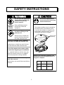
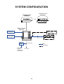
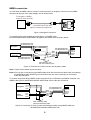
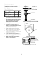
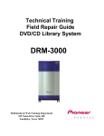
Back
Installation Manual
MARINE RADAR MODEL 1712
SAFETY INSTRUCTIONS .......................................................................... i
EQUIPMENT LISTS................................................................................... ii
SYSTEM CONFIGURATION .................................................................... iv
1. INSTALLATION..................................................................................... 1
1.1 Antenna Unit Installation..................................................................................................... 1
1.2 Display Unit Installation ...................................................................................................... 5
2. WIRING.................................................................................................. 7
2.1 Connections ....................................................................................................................... 7
3. ADJUSTMENTS .................................................................................. 10
3.1 Installation Check ............................................................................................................. 10
3.2 Exchanging Display Unit of Previous Model ..................................................................... 10
3.3 Adjustments...................................................................................................................... 10
3.4 Adjustments for Technicians ............................................................................................. 13
3.5 I/O Data Confirmation....................................................................................................... 14
3.6 Restoring Default Settings................................................................................................ 14
OUTLINE DRAWING..............................................................................D-1
SCHEMATIC DIAGRAM.........................................................................S-1
C
Your Local Agent/Dealer
9-52, Ashihara -cho,
Nishinomiya, Japan
Telephone:
Telefax:
0 7 9 8 - 6 5 - 2111
0798-65-4200
All rights reserved.
Printed in Japan
P U B . N o . I M E -3 4 8 9 0 -E 2
(HIMA)
MODEL1712
FIRST
EDITION
E2
:
:
M A Y. 2 0 0 0
D E C. 11 , 2 0 0 2
SAFETY INSTRUCTIONS
CAUTION
WARNING
Do not open the equipment
unless totally familiar with
electrical circuits and
service manual.
Ground the equipment to
prevent electrical shock and
mutual interference.
Lift the radome cover slowly.
ELECTRICAL Only qualified personnel
should work inside the
SHOCK
equipment.
HAZARD
The antenna radiator may be caught by
the screw holes in the radome cover.
If you feel the radiator is caught by the
screw holes, lower the cover, turn it a
few degree and then lift it again.
Wear a safety belt and hard
hat when working on the
antenna unit.
Screw holes
(4 places)
Serious injury or death can
result if someone falls from
the radar antenna mast.
Construct a suitable service platform
from which to install the antenna unit.
Serious injury or death can result if someone falls from the radar antenna mast.
Turn off the power at the mains switchboard before beginning the installation.
Fire, electrical shock or serious injury can
result if the power is left on or is applied
while the equipment is being installed.
Observe the following compass safe
distances to prevent interference to a
magnetic compass:
Hang the redome cover on the snap
assy. after removal.
Standard
compass
Steering
compass
Display
unit
0.90 m
0.60 m
Antenna
unit
1.25 m
0.85 m
Serious injury can result if the cover falls on
someone.
i
EQUIPMENT LISTS
Standard Supply
NAME
TYPE
CODE NO.
QTY
REMARKS
Antenna Unit
RSB-0087-068
−
1
Display Unit
RDP-134-S
−
1
Installation Materials
CP03-20380
000-087-812
CP03-21700
000-088-012
5 m signal cable
CP03-21710
000-088-016
10 m signal cable
CP03-20360
000-087-468
15 m signal cable
CP03-20370
000-087-469
20 m signal cable
CP03-20350
000-087-766
Only Installation
materials for display
unit
SP03-09800
000-085-441
Spare Parts
1 set
1 set
No signal cable
Fuse for display unit
Installation Materials
NAME
TYPE
CODE NO.
QTY
REMARKS
Signal Cable (5 m)
MJ-A10SPF0009-050 000-144-562
Signal Cable (10 m)
MJ-A10SPF0009-100 000-144-563
Signal Cable (15 m)
MJ-A10SPF0009-150 000-144-564
Signal Cable (20 m)
MJ-A10SPF0009-200 000-144-565
Power Cable Assy.
MJ-A3SPF0019-035
000-144-258
1
Connector, fuse, 3.5 m
Hex. Bolt
M10X25
000-862-308
4
For antenna unit
Dummy Film
03-118-1103-0
100-185-380
1 set
For display unit
Tapping Screw
5X20
000-802-081
4
For display unit
EMI Core
RFC-10
000-141-085
1
For signal cable
Washer Head Screw
M4X15
000-881-448
1
For signal cable
EMI Core Fixing
Plate
03-146-0101-0
100-277-850
1
For signal cable
Select one, connector at both
ends
1
ii
Spare parts
SP03-09800 (000-085-441)
NAME
Fuse
TYPE
CODE NO.
FPB0-A 5A AC125V
QTY
000-549-064
1
REMARKS
For display unit
Optional Equipment
NAME
Antenna Unit
Cable Assy.
TYPE
CODE NO.
QTY
RSB-0087-068
−
1
RSB-0060-068
−
1
REMARKS
MJ-A6SPF0003-050
000-117-603
1
Connector at one end,
5m
MJ-A6SPF0009-100
000-125-236
1
Connector at one end,
10 m
MJ-A10SPF0009-300
000-144-566
1
Connector at one end,
24 V spec. only.
Radome Mounting
Bracket
OP03-93
008-445-080
1
For sailboat
Remote Display
FMD-1712
External Buzzer
OP03-168
Antenna Cable Assy.
-
1
008-462-790
1
Rectifier
PR-62
000-013-484
PR-62
000-013-485
Connector at one end,
1 m and MJ-XH
connector
100VAC
110VAC
1
Signal Cable
PR-62
000-013-486
220VAC
PR-62
000-013-487
230VAC
MJ-A10SPF0009-050
000-144-562
Connector at both ends,
5m
MJ-A10SPF0009-100
000-144-563
Connector at both ends,
10m
1
MJ-A10SPF0009-150
000-144-564
Connector at both ends,
15m
MJ-A10SPF0009-200
000-144-565
Connector at both ends,
20m
iii
SYSTEM CONFIGURATION
ANTENNA UNIT
RSB-0060
ANTENNA UNIT
RSB-0087
OR
DISPLAY UNIT
RDP-134
External Buzzer
OP03-168
Navigator (GPS, etc.)/
Video Sounder
Video Sounder
Remote Display
FMD-1712
Navigator (GPS, etc.)
Rectifier
PR-62
Power Cable
Option
Local Supply
Ship's Mains
100/110/
220/230 VAC
1φ, 50/60 Hz
12-24 VDC
iv
1. INSTALLATION
1.1 Antenna Unit
Installation
Antenna unit
Mounting considerations
When selecting a mounting location for the
antenna unit keep in mind the following points.
• Install the antenna unit on the hardtop, radar
arch or on a mast on an appropriate platform.
(For sailboats, a mounting bracket is
optionally available.) It should be placed
where there is a good all-round view with, as
far as possible, no part of the ship’s
superstructure or rigging intercepting the
scanning beam. Any obstruction will cause
shadow and blind sectors. A mast, for
instance, with a diameter considerably less
than the width of the antenna unit, will cause
only a small blind sector. However, a
horizontal spreader or crosstrees in the
same horizontal plane would be a much
more serious obstruction; place the antenna
unit well above or below it.
Antenna unit
Figure 2 Typical antenna unit placement on
powerboat
• In order to minimize the chance of picking up
electrical interference, avoid where possible
routing the antenna cable near other
electrical equipment onboard. Also avoid
running the cable in parallel with power
cables.
• The compass safe distance of 1.25 meters
(standard compass) and 0.85 meters
(steering compass) should be observed to
prevent deviation of the magnetic compass.
Antenna unit
Antenna unit
Figure 1 Typical antenna unit placement on
sailboat
1
4.
Mounting on a platform
1.
Unfasten four screws to remove the cover.
Discard the packing material in the
radome.
Remove mounting hardware at the bottom
of the antenna unit; four each of hex bolts
(M10X20), spring washers and flat washers.
Save mounting hardware to use it to fix the
antenna unit to the mounting platform later
on.
Snap holder
Stern
Bow
Screws
Remove and discard
the packing material.
two screws on other side
Flat washer
Spring washer
Hex bolt (M10 x 20)
Figure 5 Antenna unit, inside view
Figure 3 Antenna unit, showing location of
mounting hardware
2.
The mounting base is fitted with a snap
holder. which may be used to hang the
cover after removal. Use the hole next to
screw hole inside the cover to hang it.
Construct a platform (wood, steel, or
aluminum) of 5–10 mm in thickness
referring to the outline drawing at back of
this manual. Fasten the platform to the
mounting location. Next, position the base
so the cable entrance faces the stern
direction.
Note: When drilling holes in the platform,
be sure they are parallel with the fore and
aft line.
3.
Note: Longer hex bolts (M10X25) are
supplied with the installation materials. Use
them instead of the hex bolts removed
earlier if the mounting platform is very thick.
Antenna base
assy.
5-10 mm: M10x20
10-15 mm: M10x25
Flat
washer
Spring
washer
Unfasten the snap assy. with the string
attached at the holder in the mounting
base.
b)
Unwind the string.
c)
Attach the snap to a screw hole on the
inside of the cover.
Note: Do not hang any other objects with the
snap.
Using the hex bolts, flat washers and
spring washers removed at step 1, fasten
the base to the platform. The torque
should be between 19.6-24.5 N••m.
Transceiver
module
a)
Platform
Hex bolt
(M10 x 25
or M10 x 20)
Figure 4 How to fasten the base to platform
2
5.
Unfasten the cable of the rotation detector
from the cable clamps.
6.
Unfasten 11 screws to dismount the shield
in the
plate. Discard screw marked with
Figure 6.
Cable clamp
8.
Referring to Figure 8, fasten the shield
cable with screw (M4x10) on the chassis to
ground the unit.
Shield plate
Rotation detector
Caution
Connect 9 pin
connector
here (J801).
Connect
shield here.
Figure 8 How to connect the antenna cable
to the antenna unit
9. Attach EMI Core (supplied) to antenna
cable. Set the fixing band to the EMI core.
Figure 6 Antenna unit, inside view
Fixing band
Caution: Be careful not to pinch the
rotation detector cable when remounting
the shield plate.
7.
This bend should be
facing toward you.
Pass the antenna cable with connector
through the gasket and cable clamp, and
then tighten cable gland.
Be sure the shrink tubing on the antenna
cable is not covered by the gasket.
Figure 9 Fixing band
10. Referring to Figure 8, connect the 9-pin
connector of the antenna cable to J801.
11. Refasten the shield plate with 10 screws.
Be sure not to pinch cable from the rotation
detector with the shield plate. See “Caution”
in Figure 6 for details.
Rubber gasket
12. Fasten the Fixing band with Screw
(supplied).
Screw(M4X15)
Gasket
Cable Gland
Sectional view
Fixing
Band EMI Core
Rubber gasket
Align bend with
corner of chassis.
Figure 10 How to fix the EMI Core
13. Follow the instructions on the label inside
the mounting base to secure the snap assy.
14. Confirm that the rubber gasket is properly
positioned and that the triangle mark on the
radome cover is aligned with the triangle
mark on the mounting base, then tighten
the fixing screws for the cover. Refer to
Figure 7 for positioning of rubber gasket.
Mounting base
Figure 7 Antenna unit, inside view
3
Mounting using the optional
mounting bracket
1. Remove mounting hardware at the bottom
of the antenna base. You may discard the
hardware. Assemble the mounting bracket
and fasten it to a mast. Fasten the antenna
unit to the bracket.
A mounting bracket for fastening the antenna
unit to a mast on a sailboat is optionally
available (Type OP03-93, Code
No.008-445-080).
Name
Type
Code No.
Qty
Hex. bolt
M4X12
000-804-725
4
Hex. bolt
M8X20
000-805-707
8
Mounting
plate
03-018-90
01-0
100-206-740
1
Support
plate (1)
03-018-90
05-0
100-206-780
1
Support
plate (2)
03-018-90
06-0
100-206-790
1
Bracket (1)
03-028-91
01-0
100-206-810
1
Bracket (2)
03-028-91
02-0
100-206-820
1
Fixing plate
03-028-91
03-0
100-206-830
2
Figure 11 How to assemble and mount the
optional mounting bracket
2.
4
Refer to previous steps 3-14 in "Mounting
on a platform".
Removing cover
1.2 Display Unit
Installation
While pressing the center of the cover with your
thumbs as illustrated, pull the cover towards
you to remove it.
Mounting considerations
When selecting a mounting location for the
display unit keep in mind the following points.
• Locate the display unit in a position where
you can view and operate it conveniently.
• The orientation of the display unit should be
so the radar screen is viewed while the
operator is facing in the direction of the bow.
This makes determination of your position
much easier.
• The display unit is designed and constructed
to be splashproof, thus it can be installed
outdoors. If it is to be installed outdoors, we
recommend installing it an enclosed cabinet,
for maximum protection against the marine
environment.
Mounting
The display unit can be mounted on a tabletop,
the overhead, or flush mounted in a panel.
1.
• Even though the picture is quite legible even
in bright sunlight, keep the display unit out of
direct sunlight or at least shaded because of
heat that can build up inside the cabinet.
Fix the hanger to the mounting location
with four tapping screws (supplied).
2.
Attach the anti-vibration pads to the
hanger.
• The temperature and humidity of the
mounting location should be stable and
moderate. No LCD can provide adequate
contrast if the ambient temperature is too
low or too high.
3.
Fit the knob bolts and anti-vibration rubbers
to the display unit.
4. Cover the unused bolt holes with the
dummy films supplied.
5.
• Make sure you allow enough clearance both
to get to the connectors behind the unit and
to allow you to get your hands in on both
sides to loosen or tighten the mounting
knobs. Make sure you leave at least a foot or
so of "service loop" in cables behind the unit
for servicing or easy removal of the
connectors.
• The compass safe distance of 0.90 meters
(standard compass) and 0.60 meters
(steering compass) should be observed to
prevent deviation of the magnetic compass.
5
Install the display unit in the hanger.
Tighten the knob bolts securely.
OVERHEAD MOUNT
TABLETOP
MOUNT
HARD
COVER
200
Confirm the anti-vibration pad are
attached at both side of the hanger.
DUMMY FILM
Cover unused
knob bolt holes
with dummy film
(supplied).
200
4-φ6
FIXING
HOLES
HANGER
KNOB
BOLT
192
192
80*
93
CUTOUT SIZE
FOR PANEL
MOUNTING
*150
209
* SERVICE
70
12
11
CLEARANCE
Figure 12 Mounting dimensions of display unit
6
All dimensions
in millimeters
2. WIRING
Connection of external
equipment
2.1 Connections
Connect the antenna cable, the power cable
and the ground wire as shown in Figure 13.
Navigator/echosounder
ANTENNA UNIT *1
This radar can receive the following NMEA
0183 format data sentences from a navigator or
echosounder:
Signal cable
(select one)
MJ-A10SPF0009-050 (5m)
MJ-A10SPF0009-100 (10m)
MJ-A10SPF0009-150 (15m)
MJ-A10SPF0009-200 (20m)
MJ-A10SPF0009-300 (30m)
GLL:
BWR:
DISPLAY UNIT
Power cable
MJ-A3SPF0019-035 (3.5m)
*2
BWC:
GLC:
GTD:
RMA:
RMB:
FUSE (5A)
RMC:
WHT (+)
GROUND
Connect ground
wire to bolt fastened
(or welded) to hull.
+
BLK (-)
POWER SUPPLY
12/24 VDC
VTG:
MTW:
DBT:
DBS:
DPT:
*1 :
*2
GGA:
Antenna of MODEL 1622,
1621 or 1621M2 is available.
: Optional for 24 VDC ship's
mains only.
Figure 13 Connections
7
Geographic position - Lat/Long
Bearing and Distance to Waypoint Rhumb line
Bearing and Distance to Waypoint
Geographic Position - Loran-C
Geographic Position - Time Difference
Recommended Minimum Specific
Loran-C Data
Recommended Minimum Navigation
Information
Recommended Minimum Specific
GPS/Transit Data
Track Made Good and Ground Speed
Water Temperature
Depth Below Transducer
Depth Below Surface
Depth Below Transducer with offset
value
GPS - Rx status, L/L
NMEA connection
You will need an NMEA cable to connect a video sounder or a navigator. Connect it to the NMEA
connector at the rear of the radar display unit as shown below.
To navigator or NMEA
output of video sounder
MJ-A6SPF0012-050/100
(option of external equipment)
Figure 14 Navigator connection
To connect both a video sounder and a navigator, use NMEA cable
MJ-A6SPF0003-050/MJ-A6SPF0009-100 (option) and solder them as shown below.
MJ-A6SPF0003-050
MJ-A6SPF0009-100
WHT
BLK
Note 1
Navigator
MODEL1712
MJ-A6SPF0003-050
MJ-A6SPF0009-100
SHIELD
Video
Sounder
MJ-A6SPF0003-050
MJ-A6SPF0009-100
WHT
BLK
YEL
GRN
SHIELD
WHT
BLK
Note 1
1
2
3
4
6
NMEA
RD1-H
RD1-C
RD2-H
RD2-C
GND
SHIELD
After soldering, wrap
with self-vulcanizing tape.
Figure 15 Connection of video sounder and navigator cables
Note 1: Tape unused cables to prevent short.
Note 2: Do not use a cross wiring-type NMEA cable which has connectors at both ends (for example,
MJ-A6SPF0012-050). Miswiring can result when the one of the connectors is removed to
make the connection.
To connect equipment whose NMEA output uses other than a FURUNO 6 pin NMEA connector, use
NMEA cable type MJ-A6SPF0003-050/MJ-A6SPF0009-100 to make the connection.
NMEA OUTPUT
TX-H
Navigator TX-C
GND
NMEA OUTPUT
TX-H
Video
TX-C
Sounder
GND
MODEL1712
MJ-A6SPF0003-050
MJ-A6SPF0009-100
WHT
BLK
YEL
GRN
SHIELD
1
2
3
4
6
NMEA
RD1-H
RD1-C
RD2-H
RD2-C
GND
After soldering, wrap
with self-vulcanizing tape.
Figure 16 Connection of video sounder and navigator cables using NMEA cable type
MJ-A6SPF0003-050/MJ-A6SPF0009-100
8
External buzzer (option)
The optional external buzzer provides a louder
alert when the guard alarm is violated.
Connector nut
Display unit, rear cover
External buzzer
Type: OP03-168
Code No.: 008-462-790
Connector gasket
Name
Type
Code no.
Qty
MJ-XH
connector
03-2022 (2-3P)
008-463-540
1
Buzzer
assy.
80-0641
008-462-800
1
1.
Unfasten screws and connector nuts to
remove the rear cover from the display unit.
2.
Place the rear cover on a workbench, out
side up. Remove the plastic hole cover from
the location shown in Figure 19 with a
Phillips screwdriver and a hammer.
Remove burrs from the hole with a fine file
or sandpaper.
3.
MJ connector
XH connector
(to J6 on the DU Board)
Figure 17 Fixing MJ-XH connector assembly
60 mm
Insert the MJ connector (supplied as
option) in the hole made at step 2 as shown
in Figure 17. And then fasten the connector
nut with 0.76-0.78 N•m torque.
4.
Plug in the XH connector at the end of
above connector into J6 on the DU Board.
5.
Fasten screws and connector nuts to
reassemble the display unit. Torque should
be between 0.76-0.78 N•m.
6.
Fasten the buzzer near the display unit
(within 1 m) with two tapping screws (3X15
or 3X20; local supply).
7.
Attach the connector from the external
buzzer to the MJ connector.
50 mm
2-φ3.5
Figure 18 External buzzer
External Buzzer
Remove hole cover with Phillips
screwdriver and hammer.
Remove burrs from hole with
fine file or sandpaper. Attach
connector (supplied as option).
J6 located at right
side of shield case
under the rear panel.
Figure 19 Display unit, rear view
9
3. ADJUSTMENTS
3.1 Installation Check
After installing the system it is a good idea to
check it for proper installation, following the
checklist provided below.
2.
Select MODEL by %.
3.
Select 1622 or 1621/M2 by .
4.
Press the [MENU] key to close the menu.
3.3 Adjustments
❒ Cable gland is facing toward the stern.
❒ Four fixing bolts securing the antenna unit
are securely tightened.
Do the following in order to adjust the radar.
❒ The signal cable is waterproofed at the base
of the antenna unit.
1) Adjustment of picture
❒ The antenna cable is securely retained
against the mast or mounting and is free of
interference from running rigging.
1. Press the [POWER] key on the display unit.
The display should light. In approximately
one minute, ST-BY appears at the screen
center.
❒ The cable gland on the deck or bulkhead is
waterproofed, if provided.
2.
When ST-BY appears press the [TX] key.
The radar will start transmitting, and you
will probably see some targets, even
though the radar is not yet properly
adjusted.
3.
Adjust the GAIN to display a small amount
of noise on the screen.
4.
Press the [–] key several times to select
the minimum range. Adjust the STC to
display nearby radar targets clearly on the
screen. Too much STC action will eliminate
small targets, and too little STC action will
cause the screen to be so full of targets
and noise that it is hard to determine which
target is which as compared to visual
sightings.
❒ Connectors of external equipment are
securely plugged into the radar display unit.
❒ The power connections to the battery are of
correct polarity.
3.2 Exchanging Display
Unit of Previous Model
When exchanging the display unit of the
MODEL 1712 with that of the MODEL 1622 or
1621/1621 MARK-2, it is necessary to select
the appropriate display setting. This should be
done with the radar in stand-by.
Press % and & together for about 10
seconds to show the display shown in
Figure 20.
1 MODEL
1712
2 DISPLAY MAIN
SEL MENU
BY / KEY
▲
PROGRAM NO
03591620XX
▲
1.
1622 1621/M2
DEMO
NAV DATA (NMEA 0183)
GLL
BWR BWC GLC
RMA RMB RMC VTG
DBT DBS
DPT GGA
GTD
MTW
Figure 20 Maintenance menu
10
0.25 NM
.125
2) Heading alignment
30°
30°
You have mounted the antenna unit facing
straight ahead in the direction of the bow.
Therefore, a small but conspicuous target dead
ahead visually should appear on the heading
mark (zero degrees).
In practice, you will probably observe some
small error on the display because of the
difficulty in achieving accurate initial positioning
of the antenna unit. The following adjustment
will compensate for this error, up to ±30
degrees.
Identify a suitable target (for example, ship
or buoy) at a range between 0.125 to 0.25
miles, preferably near the heading mark.
To minimize error, keep echoes in the
outer half of the picture by changing the
range.
TUNE
ADJUST PICTURE ORIENTATION
USING / KEYS SO THAT
HEADING MARK BISECTS TARGET
LOCATED DEAD AHEAD.
Figure 22 Display for adjustment of heading
Press and hold down and together
(about 10 seconds) to display the
installation menu.
hours radar
Total hours radar Total
has been transhas been on
mitted
Menu
TOTAL ON TIME
00000 : 00
TOTAL TX TIME
00000 : 00
▲
2.
1. ADJ HDG
2. ADJ TMG
3. NM /KM
▲
1.
SEL MENU
BY ▼/▲ KEY
4.
Press or to bisect the target selected
at step 1 with the dot-dash-line.
5.
Press MENU.
0.25 NM
TOTAL ON TIME
00000 : 00
TOTAL TX TIME
1. ADJ HDG
00000 : 00
2. ADJ TMG
TUNE
3. NM /KM
SEL MENU
BY ▼/▲ KEY
.125
Target
Heading
marker
▲
▲
ADJUST PICTURE ORIENTATION
USING / KEYS SO THAT
HEADING MARK BISECTS TARGET
LOCATED DEAD AHEAD.
Tuning bar
(for technicians)
Instructions for item selected appear here.
(example: heading adjustment)
Figure 21 Installation menu
3.
Select ADJ HDG. Your display should now
look something like the one shown in
Figure 22.
9.4
0.015 NM
Figure 23 How to adjust heading
6.
11
As a final test, move the boat towards a
small buoy and confirm that the buoy
shows up dead ahead on the radar when it
is visually dead ahead.
3) Sweep timing
SEL MENU
BY ▼/▲ KEY
This adjustment ensures proper radar
performance, especially on short ranges. The
radar measures the time required for a
transmitted echo to travel to the target and
return to the source. The received echo
appears on the display based on this time. Thus,
at the instant the transmitter is fired, the sweep
should start from the center of the display
(sometimes called sweep origin.)
1. ADJ HDG
2. ADJ TMG
3. NM /KM
TOTAL ON TIME
00000 : 00
TOTAL TX TIME
00000 : 00
TUNE
▲
▲
IDENTIFY STRAIGHT TARGET
SUCH AS BREAKWATER. MAKE
ITS ECHO STRAIGHT ON SCREEN
USING / KEYS.
Figure 25 Installation menu, ADJ TMG selected
A trigger pulse generated in the display unit
goes to the antenna unit through the antenna
cable to trigger the transmitter (magnetron).
The time taken by the signal to travel up to the
antenna unit varies, depending largely on the
length of signal cable. During this period the
display unit should wait before starting the
sweep. When the display unit is not adjusted
correctly, the echoes from a straight local object
(for example, a harbor wall or straight pier) will
not appear with straight edges – namely, they
will be seen as pushed out or pulled in near the
picture center. The range of objects will also be
incorrectly shown.
4.
While looking at the target selected at step
2, straighten it by pressing if it is pulled
inward, or if it is pushed outward.
4) Unit of range measurement for
VRM and cursor
The unit of range measurement for the VRM
and the cursor may be selected to nautical mile
or kilometers as follows:
1.
Select NM/KM on the menu.
SEL MENU
BY ▼/▲ KEY
1. ADJ HDG
2. ADJ TMG
3. NM /KM
<RANGE UNIT>
PRESS / KEYS TO SELECT
NAUTICAL MILE OR KILOMETER
AS THE UNIT OF RANGE.
▲
Target pushed
inward
Target pushed
outward
Figure 24 Examples of improper and
correct sweep timings
1.
Figure 26 Installation menu, NM/KM selected
Transmit the radar on 0.125 or 0.5 nm
range and adjust the sensitivity and STC.
2.
Visually select a straight echo (harbor wall,
straight pier).
3.
Press and for 10 seconds to show the
installation menu.
4.
Select ADJ TMG on the menu.
TUNE
▲
Correct
TOTAL ON TIME
00000 : 00
TOTAL TX TIME
00000 : 00
12
2.
Select unit of range desired.
3.
Press the [MENU] key to close the
installation menu.
1.
Dismount the shield plate.
3.4 Adjustments for
Technicians
1) Magnetron heater voltage
Magnetron heater voltage is formed at the MD
Board of the antenna unit and preadjusted at
the factory for use with any length of signal
cable. Therefore no adjustment is required.
However, verify heater voltage as follows:
CAUTION
MD board under
the shield plate
Lift the radome cover slowly.
Figure 27 MD board
The antenna radiator may be caught by
the screw holes in the radome cover.
If you feel the radiator is caught by the
screw holes, lower the cover, turn it a
few degree and then lift it again.
Screw holes
(4 places)
2.
Turn on the power. Do not transmit the
radar.
3.
Connect a multimeter, set to 10 V DC
range, between #6(+) and #4(-) of test
point TP804 on the MD Board in the
antenna unit.
4.
Confirm that the multimeter shows 8.0 V
±0.1 V. If it does not, adjust potentiometer
VR801 on the MD Board.
VR851
VR801
TP804
Figure 28 Antenna unit, inside view
Note: Turn the power on when measuring
magnetron heater voltage.
13
2) Radar function
3.5 I/O Data Confirmation
This radar can function as the main radar or a
demonstration model. displaying internally
generated radar echoes.
1.
Set the radar in stand-by.
2.
Press and hold down %and & together
(about 10 seconds) to display the
maintenance menu.
1
2
MODEL
1712
DISPLAY MAIN
3.6 Restoring Default
Settings
▲
SEL MENU
BY / KEY
▲
PROGRAM NO
03591620XX
You can confirm NMEA input from a navigator
or echosounder. Follow the procedure shown in
2) Radar function to display the maintenance
menu. NMEA sentences being input are shown
in reverse video.
1622 1621/M2
DEMO
NAV DATA (NMEA 0183)
GLL
BWR BWC GLC
RMA RMB RMC VTG
DBT DBS
DPT GGA
All default menu settings can be restored by
turning on the power while pressing and holding
down [MENU] and ▼.
GTD
MTW
Note: Disconnect the antenna cable to use as
demonstration model.
Figure 29 Maintenance menu
3.
Select MAIN or DEMO from the DISPLAY
field. (MAIN, Main radar display, DEMO,
demonstration display.)
4.
Press the [MENU] to close the menu.
14
Sep. 24 '02
D-2
D-3
Oct. 10,'02