1
Technical Training
Field Repair Guide
DVD/CD Library System
DRM-3000
Multimedia & Web Training Department
545 Nolen Drive Suite 100
Southlake, Texas 76092
Table Of Contents
Safety Information……………3
Test Mode………….40~43
Specifications………………….4
Troubleshooting…...44~46
Media Storage Capacity………5
Error Codes………..46~51
Accessories and Options………6
Error-Log Codes…..52~59
Panel Facilities…………………7~8
Physical Addresses….60
PCB Locations…………………9
SCSI Sense Code……61
PCB Part Numbers……………10
Diagnosis Program..62~63
Power Supply Block Diagram…11~12
Circuit Board Descriptions……13~14
Overall Wiring Diagrams……..15~20
Disassembly…………………….21~24
Carriage Base Maintenance…..25~26
Cleaning………………………..27~28
Adjustments……………………29~37
System Administrator Mode….38~39
SAFETY INFORMATION
This manual is intended for qualified service technicians ; it is not meant for the casual
do-it-yourselfer. Qualified technicians have the necessary test equipment and tools, and have been
trained to properly and safely repair complex products such as those covered by this manual.
Improperly performed repairs can adversely affect the safety and reliability of the product and may
void the warranty. If you are not qualified to perform the repair of this product properly and safely,
you should not risk trying to do so and refer the repair to a qualified service technician.
WARNING
This product contains lead in solder and certain electrical parts contain chemicals which are known to the state of California to
cause cancer, birth defects or other reproductive harm.
Health & Safety Code Section 25249.6 - Proposition 65
(FOR USA MODEL ONLY)
1. SAFETY PRECAUTIONS
The following check should be performed for the
continued protection of the customer and service
technician.
ANY MEASUREMENTS NOT WITHIN THE LIMITS
OUTLINED ABOVE ARE INDICATIVE OF A
POTENTIAL SHOCK HAZARD AND MUST BE
CORRECTED
BEFORE
RETURNING
THE
APPLIANCE TO THE CUSTOMER.
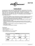
LEAKAGE CURRENT CHECK
Measure leakage current to a known earth ground
(water pipe, conduit, etc.) by connecting a leakage
current tester such as Simpson Model 229-2 or
equivalent between the earth ground and all exposed
metal parts of the appliance (input/output terminals,
screwheads, metal overlays, control shaft, etc.). Plug
the AC line cord of the appliance directly into a 120V
AC 60Hz outlet and turn the AC power switch on. Any
current measured must not exceed 0.5mA.
Reading should
Leakage not be above
current 3.5 mA
tester
Device
under
test
Test all
exposed metal
surfaces
Also test with
plug reversed
(Using AC adapter
plug as required)
AC Leakage Test
3.
Earth
ground
2. PRODUCT SAFETY NOTICE
Many electrical and mechanical parts in the appliance
have special safety related characteristics. These are
often not evident from visual inspection nor the
protection afforded by them necessarily can be obtained
by using replacement components rated for voltage,
wattage, etc. Replacement parts which have these
special safety characteristics are identified in this
Service Manual.
Electrical components having such features are
identified by marking with a on the schematics and on
the parts list in this Service Manual.
The use of a substitute replacement component which
does not have the same safety characteristics as the
PIONEER recommended replacement one, shown in the
parts list in this Service Manual, may create shock, fire,
or other hazards.
Product Safety is continuously under review and new
instructions are issued from time to time. For the latest
information, always consult the current PIONEER
Service Manual. A subscription to, or additional copies
of, PIONEER Service Manual may be obtained at a
nominal charge from PIONEER.
SPECIFICATIONS
[ 300 DISC CHANGER ]
Description ............................................... 300 disc changer
Power supply ............................. AC 100V-240V, 50/60 Hz
Power consumption ................... Maximum of 3.3A (300 W)
Weight of main unit (including placement fixtures) 60.6 kg
(133 lb 10oz)
External dimensions (including placement fixtures)
760 x 729 x 872 mm (W x D x H)
29-15/16 x 28-11/16 x 34-5/16in (W x D x H)
Operating requirements * .......................... +5°C to +35°C
Humidity * ....................... 5% to 85% (with no condensation)
Storage requirements ................................ –40°C to +60°C
* The figures for permissible operating temperature and humidity
may change depending on the components loaded. For details,
consult the operating instructions for each component used.
Functional specifications
Maximum number of discs ...................... 320 (12-cm discs)
Maximum number of disc magazines
50-disc magazines ....................................................... 6
20-disc hyper magazine ................................................ 1
Maximum number of drives .............................................. 8
Items included
20-disc hyper magazine ...................................................
Changer/drive SCSI cable .................................................
Power cord (for use in Canada and USA) ........................
Power cord (for use in Japan) ..........................................
Base stabilizer ...................................................................
Screw for use in attaching Base stabilizer ........................
Lock release key ..............................................................
Operations Instructions .....................................................
1
1
1
1
2
6
2
1
¶The external design of this product or any of the above
specifications may be changed at any time without prior
notification.
[ Accessories ]
Base stabilizer ... x 2 Changer/drive
20 disc hyper
(DNH2385)
SCSI cable ... x 1 magazine ... x 1
(DDC1006)
Power cord
(for use in Canada and USA) ... x 1
(DDG1071)
This type of power cord is for use
in America and Canada only.
Do use this power cord in places
other than America or Canada.
Power cord
(for use in Japan) ... x 1
(DDG1047)
Lock release key ... x 2
(DXC1006)
This type of power cord is for use
in Japan only.
Do not use this power cord in a
places other than Japan.
Screw for use in attaching
placement fixtures ............
Operating instructions .......
Warranty ...........................
Service network sheet ......
x6
x1
x1
x1
SCSI connector specifications
+
1
±
¡
1) Pin layout of SCSI connectors
Signal name
GROUND
GROUND
GROUND
GROUND
GROUND
GROUND
GROUND
GROUND
GROUND
GROUND
GROUND
NC
NC
NC
GROUND
GROUND
GROUND
GROUND
GROUND
GROUND
GROUND
GROUND
GROUND
GROUND
GROUND
Pin No.
1
2
3
4
5
6
7
8
9
10
11
12
13
14
15
16
17
18
19
20
21
22
23
24
25
26
27
28
29
30
31
32
33
34
35
36
37
38
39
40
41
42
43
44
45
46
47
48
49
50
Signal name
DB(0)
-DB(1)
-DB(2)
-DB(3)
-DB(4)
-DB(5)
-DB(6)
-DB(7)
-DB(P)
GROUND
GROUND
NC
TERMPWR
NC
GROUND
-ATN
GROUND
-BSY
-ACK
-RST
-MSG
-SEL
-C/D
-REQ
-I/O
NOTES:
¶ Pin No. 12 to 14, 37 and 39 are not grounded.
¶ The connectors are of the shielded type.
¶ For details on the control commands, refer to the separate
specifications manual.
2) Electrical specifications of SCSI
The signals driven by SCSI equipment
Output
characteristics present the following output characteristics.
True (LOW): VOL = 0.0 to 0.4 V DC
IOL = 48 mA (0.5 V DC) max.
False (HIGH): VOH = 2.5 to 5.25 V DC
Input
The signals driven by SCSI equipment
characteristics present the following input characteristics.
True (LOW): VOL = 0.0 to 0.4 V DC
IOL = -0.4 mA (0.4 V DC) max.
False (HIGH): VOH = 2.0 to 5.25 V DC
NOTES:
¶ As the SCSI interface is of the single-ended type, it should be
terminated on both ends of the cable
.
¶ The maximum recommended length of an SCSI cable is 6
meters (20 feet) (including internal wiring).
4.
Media Storage
Capacity
DRM-3000
Capacities
Number
OF Discs
Number of
50-disc
Magazines
Number of
Drives (when
using flip
unit)
Double
DVD
(TB)
DVD
(TB)
CD
(GB)
3.01
1.50
208
320
6
2
2.54
1.27
176
270
5
4 (2)
2.07
1.03
143
220
4
6 (4)
1.60
0.80
111
170
3
8 (6)
Capacity values are calculated using DVD storage disc Single sided = 4.7GB.
And CD-R media = 650MB.
Flip Unit required for double sided media.
Hyper Magazine increases storage by 20 discs.
5.
Accessories Or Installed
Options
DRM-AF751
DRM-AL751
50-disc Magazine
With ID Memory
50-disc Lockable
Magazine
With ID Memory
DVD-D7563
DVD Reader Unit
DVD-ROM Max 6X speed
CD-ROM Max 32X speed
DVD-R7322
DRM-AH721
DRM-UF701
20-disc Hyper magazine
Disc Flip Unit
DVD Writer Unit
Write DVD-R (2X)
Write DVD-RW (1X)
Write CD-R (4X)
Read DVD-ROM (4X)
6.
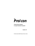
PANEL FACILITIES
FRONT PANEL
[ Front ]
1
[ Front access door INSIDE ]
[ Control panel ]
2
3
5
9
ESC
ENT
4
6
FUNCTION
LOCK
UNLOCK
7
POWER
ROBOTICS
BUSY
1 20-disc hyper magazine
2 Control panel
3 Mailslot
4 Front access door
5 LCD message window
The backlight to the LCD message window is designed
to automatically go into the dark whenever more than 1
minute passes without any operations being performed
from the control panel.
6 Operation keys
These keys are used to change the display items on the
LCD message window and to select setting fields or
values. Note that a lock release key is required in order t
o become effective these keys.
Escape key (ESC):
The escape key is used to step back from the message
layer currently being displayed (i.e., to return to the
previous display) or to halt operations.
|«:
This key is used to decrement displayed values or to
move the display cursor down or to the left.
»\:
This key is used to increment displayed values or to
move the display cursor up or to the right.
Enter key (ENT):
The enter key is used to step forward from the message
layer currently being displayed or to initiate a specified
operation.
Function key (FUNCTION):
The function key must be pressed in order to enter the
system administrator mode.
7.
DRIVE
BUSY
MAILSLOT
OCCUPIED
8
7 Lock/Unlock key switch
Inserting a lock release key into this switch and rotating it
90 degrees releases the operation lock and makes it
possible to perform operations from the control panel.
8 Status indicators
POWER:
This indicator lights up whenever the power is on.
ROBOTICS BUSY:
This indicator lights up whenever a disc transport
mechanism is in operation.
DRIVE BUSY:
This indicator lights up whenever one or more discs are
being placed on each drives.
MAILSLOT OCCUPIED:
This indicator lights up whenever a disc is placed in the
closed mailslot.
9 Front bays
For use with disc magazines: M1 – M3
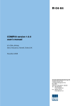
REAR PANEL
[ Rear ]
[ Rear access door INSIDE ]
2
1
9
3
4
5
TERM
OFF
ON
CHANGER
POWER
ID
SCSI
OFF
ON
AC IN
6
7
GND
8
1 Rear plates
These plates cover the space for attaching the connector
panels.
2 Rear access door
3 Drive SCSI ports (attached connector panel)
4 SCSI ID switch (ID)
This switch is used to assign the changer SCSI ID. If you
would like to decrement the displayed SCSI ID, push the
small switch just above the numeric display by a nib.
And if you would like to increment, push the small switch
just below the numeric display. Note that SCSI ID is set
to ‘6’ at the time of shipment.
6 Changer SCSI ports (CHANGER SCSI)
7 Power switch (POWER)
This switch is used to turn the power to the changer on
and off.
8 Power inlet (AC IN)
The power cord is inserted into this power inlet. (Note
that you should always be sure to use only the power
cord provided with your changer.)
9 Rear bays
For use with disc magazines : M4 - M7.
For use with optional units/modules : Bays #1 - 8.
5 SCSI termination switch (TERM)
This switch is for SCSI termination. Note that this switch
is set ON at the time of shipment and it must be kept ON
during the changer installation. But when the SCSI bus
connection is completed and the changer is not the last
device on the SCSI bus, it must be set OFF certainly.
8.
PCB LOCATION
AH
AI
[UPPER]
HMGB UNIT
D
DAA
AB
MDOT1 UNIT
MDOT2 UNIT
AP
FRPB
UNIT
[UPPER SIDE]
DSEB UNIT
AO
[MAIL SLOT]
Carriage Base
AH
AN
AM
AD
MSTB UNIT
DCMB2 UNIT
MDOR2 UNIT
ASSY
AK
UPSE UNIT
AJ
AM
AC
MSDB UNIT
MDOR1 UNIT
ASSY
AK
AM
DCMB1 UNIT
DNSE UNIT
T
Z
W
VMDB UNIT
AF
AL
SIFB1 UNIT
HFIF UNIT
ASSY
AG
A
P
G
UNIT
TMRB8 ASSY
W
V
MIF1R UNIT
ASSY
PIF2 UNIT
ASSY
A
C
POWER SUPPLY UNIT
ASSY
B
D
F
POWER SUPPLY UNIT
ASSY
PIF1 UNIT
ASSY
DIFB4 UNIT
ASSY
I
FCNB UNIT
ASSY
L
W
U
MIF2F UNIT
ASSY
DIFB3 UNIT
ASSY
C
E
POWER SUPPLY UNIT
ASSY
AE
SIFB2 UNIT
ASSY
Y
T
W
A
W
B
ACFB UNIT
PFCB UNIT
[LEFT SIDE]
X
V
CNNB ASSY
UNIT
H
SIFB2 UNIT
ENCB
ASSY MMCB
MMCBASSY
UNIT
U
[RIGHT SIDE]
J
TMNB UNIT
K
IDSB UNIT
Refer to Service Manual RRV2734 for complete parts list.
9.
PCB Part Numbers
Location
A
AA
AB
AC
AD
AE
AF
AH
AI
AJ
AK
AL
AM
AN
AO
AP
B
C
D
E
F
G
H
I
J
K
L
P
U
V
W
X
Y
Z
Description
Part Number
ACFB
MD0T1
MD0T2
MD0R1
MD0R2
SIFB2
HFIF
MSTB
HMGB
MSDB
DCMB1
UPSE
DNSE
DCMB2
DSEB
FRPB
PFCB
POWER SUPPLY 5V
POWER SUPPLY 12V
POWER SUPPLY 24V
PIF1
PIF2
MMCB
FCNB
TMNB
IDSB
MIF2F
MIF1R
DIFB3
DIFB4
VMDB
ENCB
CNNB
SIFB1
DWR1316
DWX1989
DWX1988
DWX1992
DWX1991
DWX1990
DWX1983
DWX1984
DWX1986
DWX1985
DWX1947
DWX1951
DWX1950
DWX1948
DWX1949
DWX1996
DWR1315
DWR1367
DWR1368
DWR1369
DWR1317
DRW1376
DWX2268
DWX1946
DWX1994
DWX1995
DWX1959
DWX1954
DWX1956
DWX1957
DWX1981
DWX1982
DWX1993
DWX2274
Carriage Base Service Parts:
Carriage Base Assy DXX2451
Chuck Assy DXX2348
10.
BLOCK DIAGRAM
POWER SUPPLY SIGNAL ROUTE
GND5
GND
GND12
+12V
+12V
GND
V+5.1
78
56
34
12
CN951
+5V
GND5
+12V
+5V
CN267
1234
+5V
+5V
78
56
34
12
GND5
GND5
+12v
GND12
GND12
V+12F
F
CN262
+12V
1
2
3
GND24
4
GND12
PIF2 UNIT
1
AC(N)
CN203
1
2
2
A
ACFB UNIT
AC(N)
CN255
1 -6
CN3
1 -6
1
2
4
AC 3
B
PFCB UNIT
1 -7
GND24
1 2
1 2
1 2
V-
V+
V+
8
7
IC201
8
2
10 9
VIOG AUX
PR
V-
GND24
V+24 POWER SUPPLY
ASSY
AC(L)
1 2
CN1
AC(N)
E
VAC
+24v
CN210
CN209
V+
GND12
CN207
AC(L)
CN254
CN253
CN3
GND12
+24v
1 -6
AC(N)
V+12 POWER SUPPLY
CN1
AC(L)
ASSY
V+5 POWER SUPPLY
ASSY
1 2
V-
1234
1 -7
1 2
D
AC(L)
CN201
AC(L)
CN202
AC INLET
+12V
CN1
C
1 -6
1 -6
GND5
654321
POWER SW
1 -6
CN208
CN2
DC FAN MOTOR
+12V
CN252
654321
AC(N)
CN251
CN277
12
+24v
GND5
+5V
CN2
V+12F
+5V
AC100 -240V
50/60Hz
CN261
56
34
2
1
PIF1 UNIT
+12V
GND
11.
GND5
GND12
1234
CN263
IC272
G
1234
GND12
CN951
+12V
CN266
1234
Rear Bay
#4
1234
+5V
GND5
CN951
+12V
CN265
+5V
GND5
1234
Rear Bay
#3
1234
GND12
CN951
CN271
GND12
+12V
+5V
+5V
V+12
CN264
1234
CN279
Rear Bay
#2
1234
+5V
GND5
CN951
+12V
1234
Rear Bay
#1
1234
GND12
CN275
+5V
GND5
GND12
CN951
1234
Rear Bay
#8
1234
+12V
CN274
+5V
GND5
+12V
1234
GND12
CN951
Rear Bay
#7
CN2
1
23
CN273
1234
CN279
Rear Bay
#6
+5V
GND5
CN272
+12V
1234
GND12
CN951
Rear Bay
#5
V+
CN211
V+5D
1
3
GNDD
+5
+12
Carriage Base Section
UPSE UNIT
DNSE UNIT
V+5D
V+5D
J851
J841
CN875
CN873
V+5D
CN613
CN602
+-™
~-@
V+5D
GNDD
35
79
GNDD
AK
#%
=!
+5 Volt
Regulator
GNDD
V+5D
CN876
AN
V+5D
DCMB2 UNIT
GNDD
GNDD
DCMB1 UNIT
VMDB UNIT
CN116
=&
78
V+5D
V+5D
GNDD
GNDD
V+5
CN856
3-6
@-%
1
2
IC854
V+12
SIFB2 UNIT
V+5
I
CN861
+15 Volt
Regulator
V+5
1 2
CN869
FCNB UNIT
1 2
1 2
V+5
GND5
MIF2F UNIT
CN626
CN814
V+12
V+5
GND12
V+5D
GNDD
HYPER SLOT
MAIL SLOT
GND12
GND12
VSWD12
VSWD12
GNDD
GNDD
GND12
VSWD12
GND12
VSWD12
1 V+5D
VSWD12
2
GNDD
™£
¢∞
CN901
V+5D
GNDD
GNDD
GND12
GND12
GND12
VSWD12
GNDD
!@$%^&
V+5D
CN305
!@$%^&
V+5D
!@$%^&
V+5D
GNDD
VSWD12
GND12
VSWD12
GNDD
GND12
VSWD12
V+5D
VSWD12
U
¢∞
™£
2
1
Rear Bay
#4
VSWD12
GND12
GND12
VSWD12
GNDD
VSWD12
!@$%^&
CN901
Rear Bay
#3
V+5D
CN304
!@$%^&
V+5D
V+5D
CN901
GND12
GND12
VSWD12
CN303
V+5D
!@$%^&
VSWD12
CN901
Rear Bay
#2
GNDD
GND12
GND12
!@$%^&
V+5D
GND12
CN501
GND12
DIFB4 UNIT
!@$%^&
GNDD
GNDD
V+5D
GND12
VSWD12
VSWD12
HMGB UNIT
!@$%^&
VSWD12
V
Rear Bay
#1
GNDD
AI
GNDD
CN505
GND12
VSWD12
VSWD12
CN901
V+5D
CN504
GNDD
GND12
GND12
VSWD12
CN901
V+5D
CN503
GNDD
GND12
GND12
GNDD
VSWD12
GND12
!@$%^&
V+5D
VSWD12
R
6 7
CN301
MSDB UNIT
!@$%^&
V+5D
GNDD
Rear Bay
#8
V+5
GND5
1 3
AJ
!@$%^&
V+5D
GND12
!@$%^&
FRPB UNIT
GNDD
1 3
!@$%^&
Rear Bay
#7
GND12
VSWD12
V+5D
1
2
3
4
CN302
MSTB UNIT
GND5
1
2
3
4
Rear Bay
#6
VSWD12
V+12
CN901
V+5
GNDD
AH
V+5
!@$%^&
V+5D
V+12
CN701
V+5D
6 7
GNDD
6 7
V+5
GNDD
6 7
CN803
V+5
CN805 CN802
V+5
V+5D
V+5
!@$%^&
GNDD
V+12
HMIF UNIT
V+5
GND12
GND12
AF
CN809 CN807
V+5
V+12
1
2
V+12
V+12
VSWD12
CN851
Rear Bay
#5
VSWD12
SIFB1 UNIT
13$^
25%&
GND5
V+5
Z
GND12
CN901
21
1
2
V+5D
V+12
GND12
13$^
25%&
19
~!
CN112
CN502
V+5D
GNDD
GND12
CN111
V+5D
∞¢£™21
GNDD
IC130
V+12
GNDD
V+5D
IC131
VSWD12
GNDD
GNDD
GNDD
CN106
CN107
CN108
GND12
GNDD
CN102
GNDD
V+5D
V+12
V+5D
CN810
GNDD
VSWD12
GND12
V+5D
IC141
V+5D
V+5D
GNDD
1 3
1 2
V+5D
MMCB UNIT
GNDD
GND12
MDOR2 UNIT
GNDD
GNDD
H
+12v IC144
V+5D
1 2
V+5D
AD
MDOR1 UNIT
1 2
CN104
V+5D
V+5D
CN421
GNDD
GNDD
1 2
V+5D
IC142
IC145
GNDD GND15 GND12
V+12
VSWD12
VSWD15
CN801
56
34
2
1
+5V IC143
~@$^
12 !# % &
AC
V+5D
V+5D
CN103
V+5D
V+5D
CN105
V+5D
CN101
MIF1R UNIT
GND5
GNDD
L
V+5
1 2
V+5
P
AE
GND5
GND12
CN860
CN117
CN868
W
GND12
GND12
CN601
~@$^
12!#%&
2 3
CN872
V+5D
+15
2 3
V+5D
CN871
1 4
GNDD
V+5D
-12
DC to DC
Converter
4 3
GNDD
IC616
GND15
VSWD12
V-12
1 4
GND24
IC615
GND12 IC620
VSWD15
IC617 IC619
2 3
GNDD
GNDD
VSWD15
V+5D
V+12
IC621
4 3
V+5D
CN606
VSWD12
4321
J831
V+5D
GNDD
2 3
CN874
X
+24
AO
V+5D
GNDD
ENCB UNIT
DSEB UNIT
AM
AL
GNDD
DIFB3 UNIT
CN306
1
2
™£
¢∞
GND12
12.
Circuit Board Descriptions
(A) ACFB unit. Connects to the AC line cord input and power switch. Contains a
AC line filter and main 6.3 amp 250 volt fuse.
(B) PFCB unit. Power Factor Improvement Module. Receives AC input from
ACFB unit and provides the AC supply for the three power supplies. (C), (D)
and (E).
(C) +5 Volt Power Supply. Supply for PCB units and bays.
(D) +12 Volt Power Supply. Supply for PCB units and bays.
(E) +24 Volt Power Supply. Supply for VMDB unit (Vertical Motor Drive
board).
(F) PIF1 unit. Power interface assembly for rear bays 1~4.
(G) PIF2 unit. Power interface assembly for rear bays 5~8, DC fan power
connector and fan FG circuit.
(H) MMCB unit. Main Microprocessor Circuit Board. This unit contains the
main CPU, SCSI interface, Flash Rom and integrated circuit protectors for
+5 and +12 volt supplies.
(I) FCNB unit. Interconnect from MMCB to DCMB1 units. Contains the
up/down interrupter LED’s for vertical drive motor stop position. (Fixed).
(J) TMNB unit. Contains the SCSI termination switch and provides the feed
through from the MMCB to the IDSB units.
(K) IDSB unit. SCSI ID selector for the changer.
(L) MIF2F unit. Touch Memory Interface Assembly. Connects from touch
memory units (M, N and O) to the MMCB unit. (See service manual for
locations of magazine touch memory units).
(P) MIF1R unit. Touch Memory Interface Assembly. Connects from touch
memory units (Q, R, S and T) to MMCB unit.
(U) DIFB3 unit. Rear Bay 1~4 SCSI Terminal Interface.
(V) DIFB4 unit. Rear Bay 5~8 SCSI Terminal Interface.
(W) VMDB unit. Vertical Motor Drive Board. Contains the vertical motor drive
circuit, door switches and front/rear door plunger drivers.
13.
(X) ENCB unit. Up/Down rotation detector. Connects to the VMDB unit.
(Y) CNNB unit. Vertical Motor Connector Assembly.
(Z) SIFB1 unit. Disc Detect Sensor Adjustment Board.
(AA) MDOT1 unit. Front Disc Sensor LED Board.
(AB) MDOT2 unit. Rear Disc Sensor LED Board.
(AC) MDOR1 unit. Front Disc Sensor (photo coupler).
(AD) MDOR2 unit. Rear Disc Sensor (photo coupler).
(AE) SIFB2 unit. Sensor interface board. Connects to disc sensors, door switches
and the MMCB unit.
(AF) HMIF unit. Hyper Magazine Interface Board. Signal interface to and from
the MMCB unit.
(AH) MSTB unit. Mail slot tray motor connector, tray open/close switch and
rotation encoder connector.
(AI) HMGB unit. Hyper magazine loading motor connector, sensor release
switch and load/unload switch connector.
(AJ) MSDB unit. Mail Slot Rotary Encoder.
(AK) DCMB1 unit. Carriage Base Main Interconnect Assembly.
(AL) UPSE unit. Carriage base up sensor assembly.
(AM) DNSE unit. Carriage base down sensor assembly.
(AN) DCNB2 unit. Carriage base loading motor connector and disc detect LED
assembly.
(AO) DSEB unit. Carriage base disc detector adjustment assembly.
(AP) FRPB unit. Front Panel PCB Board. Function LED’s, function button
assembly, LCD module connector and key lock interface.
14.
OVERALL WIRING DIAGRAM (1/3)
DC FAN
MOTOR
DXM1183
Rear Bay
#8
Rear Bay
#7
G
PIF2 UNIT
(DWR1376)
+5v
C
Rear Bay
#6
POWER SUPPLY
ASSY (DWR1367)
Rear Bay
#5
+12v
D
POWER SUPPLY
ASSY (DWR1368)
Rear Bay
#4
Rear Bay
#3
Rear Bay
#2
F
PIF1 UNIT
(DWR1317)
+24v
E
POWER SUPPLY
ASSY (DWR1369)
Rear Bay
#1
SWITCHING REGULATOR
POWER SW
DSA1027
POWER CORD
DDG1071 (for North American)
DDG1047 (for Japan)
3P INLET ASSY
DKN1194
15.
A
B
ACFB UNIT
(DWR1316)
PFCB UNIT
(DWR1315)
(3/3)
J
TMNB UNIT
(DWX1994)
(1/3)
UNIT
K IDSB
(DWX1995)
(1/3)
(1/3)
To
CHANGER SCSI
TERMINAL
(2/3)
H H 1/3- H 3/3
MMCB UNIT (DWX2268)
(2/3)
(1/3)
A
B
C
D
E
16.
P
MIF1R UNIT
(DWX1954)
MIF2F UNIT
(DWX1959)
T
M
TMRB1 UNIT
(DWX1966)
A
B
C
E
17.
Magazine 3
N
TMRB2 UNIT
(DWX1967)
TMRB6 UNIT
(DWX1971)
TMRB5 UNIT
(DWX1970)
Magazine 1
O
TMRB3 UNIT
(DWX1968)
Magazine 2
TMRB7 UNIT
(DWX1972)
S
R
Q
TMRB4 UNIT
(DWX1969)
Magazine 6
L
Magazine 5
Rear Side
Magazine 4
Front Side
Magazine 7
OVERALL WIRING DIAGRAM (2/3)
Rear Bay
#6
Rear Bay
#8
V
Rear Bay
#5
Rear Bay
#2
DIFB4 UNIT
(DWX1957)
U
Rear Bay
#7
Rear Bay
#4
DIFB3 UNIT
(DWX1956)
Rear Bay
#1
Rear Bay
#3
18.
OVERALL WIRING DIAGRAM (3/3)
CARRIAGE ASSY-S
(DXX2451)
AM
FCNB UNIT
(DWX1946)
DNSE UNIT
(DWX1950)
AL
(2/3)
I
UPSE UNIT
(DWX1951)
AK
DCMB1 UNIT
(DWX1947)
AO
AN
DCMB2 UNIT
(DWX1948)
FOR ADJ
DSEB UNIT
(DWX1949)
DISC DET.
SENSOR ADJ.
LOADING MOTOR
ASSY-S
DXX2522
SHIPPING
SW (L)
DSK1007
(2/3)
SHIPPING
SW (R)
DSK1007
(2/3)
MAIL SLOT SECTION
AG
TRAY O/C
DET. SW
DSK1003
(2/3)
HIPER MAGAZINE SECTION
LOAD END/
UNLOAD SW
DSK1003
HP LOADING
MOTOR ASSY-S
DXX2452
HMGB UNIT
(DWX1986)
AF
AI
RELEASE
SENSOR
SW
VSH1017
19.
(2/3)
AH
TRAY
MOTOR
PXM1002
MSTB UNIT
(DWX1984)
AJ
MSDB UNIT
(DWX1985)
TMRB8 UNIT
(DWX1973)
HMIF UNIT
(DWX1983)
DOOR SW F
DSK1007
X
ENCB UNIT
(DWX1982)
DOOR SW R
DSK1007
Z
VD
MOTOR
DXM1086
PLUNGER F
DXP1044
SIFB1 UNIT
(DWX2274)
DISC DET.
SENSOR
ADJ
DISC DET.
SENSOR
ADJ
UNIT
Y CNNB
(DWX1993)
UP/DOWN
SPEED
ADJ
VR601
PLUNGER R
DXP1044
FERRITE CLAMP
DTH1177
W W 1/3- W 3/3
AA
MDOT1 UNIT
(DWX1989)
VMDB UNIT (DWX1981)
AC
MDOR1 UNIT
(DWX1992)
D
(1/3)
AB
MDOT2 UNIT
(DWX1988)
AD
MDOR2 UNIT
(DWX1991)
FOR
FACTORY ADJ
(2/3)
(2/3)
AE
SIFB2 UNIT
(DWX1990)
DISC DET.
SENSOR
ADJ
DISC DET.
SENSOR
ADJ
LCD MODULE (DWG1507)
H H 1/3- H 3/3
MMCB UNIT (DWX2268)
LOCK/UNLOCK
KEY SW
DXC1005
WHT
GRY
AP
LCD POWER
SUPPLY
ADJ
VR701
FRPB UNIT
(DWX1996)
20.
DISASSEMBLY
Front Door
Side Panel
1
Opening the Front Door Manually (1)
Remove the eight screws.
1
2
1
×2
1
Lift the link plate assy.
Open the front door.
×2
Link Plate Assy
Side Panel (M)
1
Side Panel (ML)
2
1
Front Door
×2
1
2
×2
Opening the Front Door Manually (2)
1
Insert a thin plate, such as a square, through the gap
between the front door and the body, horizontally about
30 mm, and move the thin plate upward until it reaches the
plate stopper.
2
Push up the plate stopper until it unlatches.
3
The front door can be opened manually.
Remove the side panel (M) and (ML) after sliding to the
sideways.
Hook
1
25 mm
Square
30 mm
2
Side Panel (M)
2
Note: Remove the side panel (ML) with the same way.
Front Door
21.
3
Plate
Stopper
Removing the VD Motor Fixing Plate
1
2
3
Remove the side panel (M), located at right viewed from
the front.
Remove the four screws.
Remove the D belt spring, S3M belt and the two connectors.
VD Motor
Note:
When reattaching the VD motor fixing plate, turn the four screws
(2) until the tensions of the D belt spring and the S3M belt (3)
are balanced.
3
2
D Belt Spring
3 3
3
S3M Belt
3
D Belt Spring
CNNB
UNIT
2
2
×2
VD Motor Fixing Plate
Rear Door
1
Insert a thin rod, such as a small-diameter screwdriver,
diagonally down approx. 50 mm through the hole at the
lower side of the rear door.
2
3
Move it to the direction indicated by the arrow.
Open the rear door.
Attaching the VD Motor
1
Attach the VD motor with two screws (PMB30P060FMC)
and a motor-sleeve screw (AMZ30P080FMC).
Run these screws in but don't tighten them yet.
2
3
Put the S2M belt.
Rear Door
3
Slide the screws (1) toward A and tighten.
VD Motor
A
1
(AMZ30P080FMC)
1
(PMB30P060FMC) x2
Motor-sleeve
1
S2M Belt
2
Thin rod, such as a smalldiameter screwdriver
22.
Drive Unit (Option)
1
Removing the PL Upper Cover of the
Drive Unit
Remove three connectors.
The PL upper cover is fixed with claws at the front and with
screws at the rear. To remove the PL upper cover, proceed
as follows. Failure to do so may damage the claws.
Drive Unit
1
2
Remove the four screw.
While pressing the PL lock lever toward RELEASE, slide
the PL upper cover backward. (It will stop after sliding
approx. 1 cm backward.)
2
1
-2
1
PL Upper Cover
×3
2
1
2
3
×2
-1
PL Lock Lever
Release the PL lock lever.
Remove the drive unit.
3
Press and bend the front part of the PL upper cover from
the left and right sides to unhook the claws, then lift up
the cover. (Do NOT try to lift up the cover forcibly with the
claws unhooked. This may damage the claws and make
it impossible to reattach the cover.)
4
Remove the PL upper cover.
PL Upper Cover
Drive Unit
3
4
2
Claw
PL Lock Lever
Reference:
The reader drive can be installed in any slot. (You can install
as many optional reader drives as there are slots available.)
4
×2
Claw
• When reattaching the cover, reverse the above procedures.
(Place the cover approx. 1 cm backward and hook the claws,
then slide the cover forward.)
• Observe the driver unit from the rear to check that the claws
are firmly engaged.
23.
Moving the Carriage Base Up and
Down Manually
1
2
3
Open the front door.
Remove the side panel (M), located at right viewed from
the front.
Rotate the pulley with your fingers clockwise to move the
carriage base downward, and counterclockwise to move it
upward.
Removing the Carriage Base
1
2
Open the front and rear doors. Turn off the power.
Move the carriage base down until it touches the under
chassis by manually rotating the shaft of the elevator motor.
Caution: If the carriage base does not touch the under chassis,
the table of the carriage base will be deformed.
Caution: If the front door switch is set to ON while the power
is on, the motor shaft will start rotating.
2
Carriage base
downward
Carriage base
Pulley
Carriage base
upward
For Shipping Stopper Screw of the Carriage
Base
3
Remove the Flexible flat cable (F.F.C )
4
Remove the four screws and remove the carriage base.
4
×4
5
Carriage base
Reattaching the Carriage Base
Reattach the carriage base with the four screws with the
table of the carriage base touching the under chassis.
Caution: Be sure to proceed with this step with the carriage
base touching the under chassis.
Otherwise, the table of the carriage base will be
deformed.
For safety, when moving the unit, fix the carriage base by
the shipping stopper screws.
Entering Adjustment Mode
Refer to "6.1 Mechanism adjustment" and "6.2 Adjustment
for mechanical operations".
24.
Maintenance of the Carriage Base
(1) Removing the Chuck Assy
3. Unlock the lock plate by sliding the plate with its side lifted.
1. Turn off the power.
2. Slide the chuck toward you by rotating the loading motor.
3. Lifting up the upper plate, pull the chuck assy from the shaft
of the planetary arm.
Lock Plate
Upper Plate
Chuck Assy
Fig. 1
Fig. 3
(2) Removing the Outer table
1. Remove the carriage base. (Refer to the section "Removing
the Carriage Base".
2. Remove two fixing screws 1 and remove the sensor stay.
Note : Make sure not to damage the wire. Also, be sure to
remember the layout of the wire before removing.
4. Grip the chuck assy and the upper plate together so that the
chuck assy will not move, and pull them out toward you.
Note: Pull out the chuck assy and the upper plate slowly
straight toward you so that the steel ball will not fall.
After pulling them out, remove the steel ball.
Upper Plate
Sensor Stay
1
Chuck Assy
Fig. 2
Fig. 4
25.
(3) Attaching the Inner Table Assy
1. Mount the inner table assy so that the tip of the planetary arm
assy is centered on the cutout of the outer table.
marks
Note: Make sure that the inner table assy is not mounted
on the flange of the outer table.
SW Arms C
Key-shaped axis of the
H Cam gear (larged)
marks
Fig. 6
Planetary Arm Assy
Planet Gear
Outer Table (cutout)
Fig. 5
(4) Mounting the Outer table
1. Align the largest, key-shaped axis of the H cam gear of the
carriage base and two SW arms C with the
marks.
2. Turn the inner table of the outer table completely
counterclockwise and keep it in that position.
Note: Grip the chuck assy and the upper plate firmly so
that the inner table will not return to its original
position under its spring tension.
3. Insert the steel ball into the slot of the outer table.
4. Align the key-shaped slot of the inner table with the keyshaped axis of the H cam gear, and mount the outer table.
(5) Attaching the SW Arms
1. Attach the SW arms as indicated in Fig. 7.
Note: There are three SW arms, labeled A, B and C.
Flexible cord
SW Arm A
DCMB Unit (to outer cam groove)
Loading Motor
Assy
SW Arm C
Note: While mounting the inner table, press it on so that the
inner table will not pop up from the outer table.
5. Slide the lock plate, and lock it.
Note: Check that the lock plate is firmly locked by lifting the
outer table.
6. Rotate the outer table one turn by rotating the loading motor.
If the SW C arms are not seated in the cam grooves, the
rotation will be locked midway. In this case, remove the
swing-full assy and repeat steps 5 through 7.
7. Lay out the wire of the sensor stay and screw on the sensor
stay.
SW Arm B
(to outer cam groove)
SW Arm C
H Cam Gear
SW Arm B
(to inner cam groove)
Fig. 7
26.
INFORMATION ON MAINTENANCE
[ NOTES ON SERVICING ]
7 Cleaning the parts
• Fan
Clean the fan before shipping. For cleaning, the following tool is required:
• Cleaning paper GED-008
7 Cleaning the chuck on the carriage base
1. Open the door. Manually rotate the Loading Motor located at the lower part of the carriage base until the chuck comes
to the front-panel side.
2. Turn the unit OFF.
3. Remove dust and dirt around the D-Guides for loading discs and the Chuck Guide on the carriage base.
7 Cleaning the Touch block of the Touch Memory
• Clean the Touch block of the Touch Memory.
7 Cleaning the Mailslot tray block
• Eject the Mailslot tray block in Test mode and clean it.
27.
7 Lubricating the carriage base
• Lubricating the outer table
Outer Table
Raise the Outer Table as shown in the
photo, and apply grease (GYA1001)
around the steel ball, taking care not to
overflow.
7 Lubricating the Planet Arm Assy
• Rotate the Loading Motor manually until the D-Guides and the chuck come out sufficiently enough lubrication
at the rear side. Care must be taken so that they do not fully protrude.
Apply grease (GYA1001) to the oval-shaped holes
(inside the circles in the photo) on the Planet Arm
Assy.
28.
ADJUSTMENTS
MECHANISM ADJUSTMENT
Tools for Adjustment
a : Phillips screwdriver (nominal No. 2 for M3 cross-recessed
head machine screws)
b : Phillips screwdriver (nominal No. 3 for M2.6 cross-recessed
head machine screws)
c : Flat-head screwdriver (nominal 5.5 × 75; for M2.6 slotted
head machine screws)
d : Hexagonal wrench (nominal 2.5 for M3 hexagon socket
head cap screws)
e : Hexagonal wrench (nominal 2 for M2.6 hexagon socket set
screws)
f : Door key
g : Screw-fixing adhesive
[Screw-fixing adhesive #300UB: ZBA-300UB]
h : Adjustment disc [GGF1287]
i : Adjustment filter [GGF1287]
j : Flat-head screwdriver for volume adjustments
(2.4mm, non-conducting type or an equivalent)
k : Adhesive (Arontite R: ZBA-UR)
l : Magazine for 50 discs (DRM-AF751)[GGF1435]
∗ Sufficient care must be taken as the chuck block is protruded if
you rotate the turntable clockwise in manual loading operation
of the Test mode (Diag → Robotics → Individually).
It can cause damage if protruded in a location other
than the disc rack and player.
Indications a to l at the end of paragraphs in the following
indicate the tools to be used in the respective steps.
(1) Remove the side panel (right side) and the top panel. a
Preparations for Adjustment
• For adjustments of the mechanical operations
(1) Remove the side panel (right side) and top panel. a
(2) Open the front door and pull out the magazines. f
Caution: Be careful when performing this step, because this
unit operates at a high speed.
∗ As adjustments are to be performed with visual observation,
set the unit in a well-lit place, such as under a fluorescent lamp.
∗ Note that the manual elevating operation mode of the Test
mode.
(Diag → Robotics → Individually) activates even when the D
guides have been protruded.
D guide
Chuck block
• For sensitivity adjustment of the carriage base
disc sensor
• For sensitivity adjustment of the magazine disc
out-of-position sensor
(1) Remove the side panel (right side) and the top panel. a
(2) Open the front door and pull out the under magazine. f
Adjustment Methods
• The figures in brackets, such as [001], in the following represent
the position of the carriage base displayed in the lower row of
the mode indicator when you move it up or down operation
mode.
• To move the carriage base up or down by hand, remove the side
panel (right side) and turn the pulley or the belt of the vertical
drive motor counterclockwise for upward movement,
and clockwise for downward movement.
Refer to "Moving the carriage base up or down manually " of
IN DISASSEMBLY.
• How to enter Test Mode
See TEST MODE."
29.
ADJUSTMENT FOR MECHANICAL OPERATIONS
Height Adjustment of the D Guides
L and R
• Purpose
: To adjust the top height of the D guides with
respect to the reference surface of the carriage
base.
• Method
: Turn the D guide adjustment screw
(DG height pin) on the carriage base.
• Contents : Adjust the top heights of the D guides L and R
on the carriage base.
Adjust the upper surface of the D guides to 31
± 0.2 mm higher than the reference surface of the
carriage base.
• Preparation : Press the Door SW to cancel the operation
restriction.
Enter Manual elevating operation mode of the
Test mode (Diag → Robotics → Individually).
• Adjustment point: DG height pin
• Left Side
(1) Move the carriage base to a position (around [75] to [100] )
which permits it to be seen from the front and the loading
motor to be rotated.
(2) Rotate the turntable counterclockwise in Manual operation
mode (Test → Diag → Robotics → Individually).
Caution: Do not turn it clockwise to avoid damage.
(3) Stop the rotation when the turntable has been turned about 70
degrees from the front.
(4) Using a measuring device, confirm that the distance between
the upper surface of the carriage base and the upper surface
of the D guide is 31 mm.
If not, adjust the D guide adjustment screw. c
(5) Lock the screws when the adjustment is completed. k
• Right side
(1) As with the left side adjustment, rotate the turntable
counterclockwise and stop it when it has been rotated about
290 degrees from the front.
(2) The subsequent procedures are the same as for the left side
adjustment.
Carriage base
DG height pin
Right and Left Adjustment of the
Carriage Base
• Purpose
: To adjust the carriage base so that it becomes
horizontal to the main unit.
• Method
: Move up or down the belt stopper which connects
between the elevator belt (on the right side) and
the carriage base with the eccentric bushing.
• Contents : Adjust the height of the movable mounting
position at right side against the fixed belt stopper
at left side.
Adjust the horizontal level of the carriage base so that
the difference between the right and left is less
than 0.3 mm.
• Preparation : Press the Door SW to cancel the operation
restriction.
Enter Manual elevating operation mode of the
Test mode (Diag → Robotics → Individually).
Prepare the magazine. (Be sure not to load the
upper four discs.)
• Adjustment point: Eccentric bushing
∗ Confirm the height of the D guides in advance. Be sure to
check the height of the interrupter UP when the adjustment is
completed.
(1) Move the carriage base to [99].
(2) Rotate the loading motor manually and stop rotating it
immediately after the D guides have come out from the
carriage base. Do NOT move the chuck outward.
(3) Load the magazine into magazine bay No. 2. Care must be
taken that the magazine does not touch the D guides.
If it does, move back the D guides toward the carriage base.
(4) Release the Door switch.
(5) While observing through the hole at the top of the magazine,
move the carriage base up or down manually so that the slot
of disc rack L located to your left and D guide L align.
(6) Confirm visually that the difference in height between the slot
of the disc rack R on the right side and the D guide R is less
than 0.3mm. If not, perform the following adjustment.
Disk rack L
Disc rack R
D guide L
D guide R
Chuck
DG height pin
D guide L
D guide R
Chuck
Left side
Right side
Fig. 2
Note: Do not use the position of the chuck, as it may not be
accurate.
31 ± 0.2 mm
Reference
surface
Carriage
base
31 ± 0.2 mm
Reference
surface
Carriage base
Fig. 1 Height adjustment of the D-guides
(7) Loosen the hexagon coupling bolt for fixing, then temporarily
tighten it. d
(8) If the right side is lower, turn the eccentric bushing counterclockwise as necessary, and if the right side is higher, turn it
clockwise as necessary.
(clamping torque: 68.6 Ncm (7 kgcm)) c, d
(9) Perform steps (4) to (6) for verification. If the difference still
exceeds 0.3mm, repeat steps (7) to (8) and (4) to (6).
(10) Lock the screws when the adjustments are completed. g
30.
Eccentric Bushing
If the right side
is lower.
If the right side
is higher.
Hexagon coupling Bolt
Fig.3 Right and left horizontal adjustment
Front-Rear Adjustment of the Carriage Base
• Purpose
: To adjust the carriage base so that it becomes
front-rear horizontal to the main unit.
• Method
: Adjust by turning the front-rear adjustment screw
on the carriage base.
• Contents : Adjust the horizontal of the carriage base so that
the difference between the front and rear is less
than 0.3 mm.
• Preparation : Press the Door SW to cancel the operation
restriction. Open the rear door and press the Door
SW to release the operation limit.
Enter Manual elevating operation mode of the Test
mode (Diag → Robotics → Individually).
Prepare the two magazines.
• Adjustment point: Front-rear adjustment screw
(9) If there is a difference in height, adjust by turning the frontrear adjustment screw on the carriage base. e
(10) If the D guide at the rear side is higher, turn the adjustment
screw counterclockwise. If the D guide at the rear side is
lower, turn the adjustment screw clockwise.
(11) After the adjustment is completed, repeat from Steps 5 to 10
for confirmation, then lock the screws. g
Carriage base
Adjustment
screw
∗ Confirm the height of the D guides in advance. Be sure to check
the height of the interrupter UP when the adjustment is
completed.
(1) Move the carriage base to [99].
(2) Rotate the loading motor manually and stop rotating it
immediately after the D guides have come out from the
carriage base. Do NOT move the chuck outward.
(3) Load the magazine into magazine bay No. 2. Care must be
taken that the magazine does not touch the D guides.
If it does, move back the D guides toward the carriage base.l
(4) Release the Door switch.
(5) While observing through the hole at the top of the magazine,
move the carriage base up or down manually so that the slot
of disc rack L located to your left and D guide L align.
(6) Remove the magazine, and rotate the loading motor manually
so that the D guide moves to the rear.
Note: The alarm sound of the disc sensor can be stopped by
pressing the FUNCTION button.
(7) Set the unit to the state immediately after the D guides come
out from the carriage base. Do NOT move the chuck outward.
(8) Load the magazine into magazine bay No. 5, and check from
the rear that the slot of the disc rack and the D guide align.
Confirm visually the horizontal between front and rear from
the left and right sides.
31.
Fig. 4 Front-rear adjustment of the carriage base
Height Adjustment of the Interrupter UP
• Purpose
: To align the stop position of carriage base
elevation with the disc magazine.
• Method
: Adjust by turning the interrupter UP adjustment
screw.
• Contents : Adjust the height of the interrupter UP to align the
height at which the carriage base stops with the
magazine.
• Preparation : Enter Manual elevating operation mode of the Test
mode (Diag → Robotics → Individually).
Prepare the magazine. (Be sure not to load the
upper four discs.)
• Adjustment point: Height adjustment screw
The LED for monitoring the interrupter output is
located on the FCNB Unit (interrupter UP: green).
∗ Confirm the height of the D guides in advance.
(1) Move the carriage base to [99].
(2) Manually rotate the loading motor to bring the D guides out
to the front. (Set to a state just after the D guides have come
out from the carriage base. Do not move the chuck outward.)
(3) While observing the green LED, manually move the carriage
base slightly up and stop it immediately when the green LED
lights up.
If the green LED is already lit, first move the carriage base
slightly down.
(4) When the magazine is slowly inserted, it engages with the D
guides just before it locks. While observing through the hole
at the top of the magazine, confirm that the D guides are not
moved by the magazine. If they move, perform the following
adjustment. l
(5) If the D guides move, adjust the position of green LED lights
up by the interrupter UP height adjustment screw. e
(6) Manually set the carriage base to the position where the
magazine does not touch the D guides when it moves in and
out in the above-mentioned way.
→ While moving the carriage base up or down little by little, find
a position where the D guides do not move even when the
magazine is moved in and out.
→ Find a position of the carriage base relative to the magazine.
As this position is used as the reference for adjustment of the
interrupter DN, do not move or even touch the carriage base
after its position is determined.
(7) Turn the interrupter UP height adjustment screw clockwise
and stop it when the green LED lights. (If the LED
was lit when starting the adjustment, first turn the screw
counter-clockwise to go off the LED.) e
(8) Further turn the screw 180 degrees (170 to 190 degrees)
clockwise then stop it.
Carriage base
Adjustment
screw
< Detailed explanation >
Encoder side
Carriage base side
Clockwise rotation moves
UP Interrupter to upwards.
Clockwise rotation moves
DN Interrupter to upwards.
phase difference / 2
9 mm
9.45 mm
(pitch 3mm × 3 teeth)
UP
B
phase difference / 2
(9 + phase difference 0.45)
A
C
• The figure to the left shows the center of the stop position of the
carriage base. The purpose of the adjustment is to obtain this
status. The stop position requires A > 0 and B > 0.
This means that the stop position range must be ± phase
difference/2 and the stop-position range must be equal to the
phase difference. Thus, as shown in the figure to the left, set
DN (reference side) to phase difference/2 below and UP
(adjusting side) to phase difference/2 above with respect to the
lower edge of the encoder slit.
• Adjust A in the height adjustment. Align the target lower edge of
the encoder slit with the position of UP (= the position of the
carriage base) [step (7)], then move it up by the amount of A
[step (8)].
DN
Interrupter
Encoder plate
Fig. 5 Height adjustment of the interrupter UP
Lower edge
for reference
Clockwise for upwards
and counterclockwise
for downwards.
A
UP
UP
∗ The interrupters light when the light is blocked.
Fig. 5 Adjustment model view
32.
Phase Adjustment of the UP-DN
Interrupters
• Purpose
: To adjust the stop position range of carriage base
elevation to 0.45 mm.
• Method
: Adjust by turning the Phase-adjustment screw on
the carriage base.
• Contents : Set the interrupter UP 0.45mm higher than the
interrupter DN. Adjust the phase difference
(relative height) between UP and DN to 0.45 ±
0.05 mm.
• Preparation : Enter Manual elevating operation mode of the
Test mode (Diag → Robotics → Individually).
• Adjustment point: Phase-adjustment screw
The LEDs for monitoring the interrupter outputs
are located on the FCNB Unit (interrupter UP:
green, interrupter DN: red).
(1) Move the carriage base to [99] to permit easy access to the
phase-adjustment screw.
(2) While observing the green LED, slowly move the carriage
base up by hand and stop it immediately when the green LED
lights.
Important: Be sure to stop the carriage base in an upward
movement.
(3) Turn the phase-adjustment screw clockwise and stop it when
the red LED lights. (If the LED is already lit when starting
the adjustment, once turn the screw counterclockwise to turn
the LED off.) e
(4) Verification: Move the carriage base down until the red LED
goes off, then slowly move it up again to check that the two
LEDs simultaneously light. If they do not light simultaneously, repeat the adjustment from step (2).
(5) While observing the red LED (interrupter), slowly move the
carriage base up or down by hand and stop it immediately
when the red LED lights. Be sure to stop the carriage base in
an upward movement.
(6) In the state when the red LED lights, turn the phaseadjustment screw clockwise 360 degrees (350 to 370 degrees).
Be sure to finish the adjustment by turning the phaseadjustment screw clockwise. For example, turn the screw
counterclockwise by 390 degrees, then turn it clockwise by
30 degrees to finish the adjustment.
(7) Lock the screws when the adjustment is completed. g
< Detailed explanation >
Clockwise for upwards and
counterclockwise for downwards
UP
9mm
9mm
UP
DN
C
DN
∗ The interrupters light when the light is blocked.
Adjust C ( A + B ) in the UP-DN phase adjustments.
After aligning the UP interrupter with the lower edge of the encoder
slit (step 2), temporarity align the interrupter DN also with the lower
edge (step 3).
After confirming that the DN and UP interrupters are in place (step
4), align the interrupter DN with the lower edge again (step 5) and
move the interrupter DN downwards by the amount of C (step 6).
Fig. 7 Adjustment model view
33.
Adjustment screw
Fig. 8 Phase adjustment of the UP-DN interrupters
Verification of Operations After
Adjustments
Height adjustment of the D Guides
Right and left,
front and back
adjustment
Height adjustment
Relative adjustment of the
UP and DN interrupters
Verification
• Be sure to confirm the height of D guides before the right and
left adjustment and front and back adjustment of the carriage
base and the height adjustment of the interrupter UP.
• Be sure to check the height of the interrupter UP when the right
and adjustment and front and back adjustment of the carriage
base have been performed.
• Perform the relative adjustment of the UP and DN interrupters
in conjunction with other adjustments as required.
Perform the verification of operations after the height adjustment
of the D guides, right and left adjustment and front and back
adjustment of the carriage base, height adjustment of the
interrupter UP, or relative adjustment of UP-DN interrupters is
completed.
(1) Set the unit to Manual elevating operation mode of the Test
mode (Diag → Robotics → Individually).
(2) Move the carriage base to [99].
(3) Set the upper magazine only. (Be sure not to set the upper
four discs.)
(4) Rotate the turntable in Manual loading operation mode of the
Test mode (Diag → Robotics → Individually) to move the D
guides out towards the front and rotate the table in the reverse
direction to return to a position where the magazine does not
touch the D guides.
→ Set to the state just before the turntable starts rotating.
Caution: A manual loading operation may not be allowed,
depending on the position of the carriage base or turntable. Be
sure to just lightly touch (or momentarily push) the switch when
operating it.
(5) Observe through the hole at the top of the magazine to check
that there is no misalignment in gear teeth or in height
between the slot of the disc rack R on the right side and the D
guide R or between the slot of the disc rack L on the left side
and the D guide L.
SENSITIVITY ADJUSTMENT OF THE CARRIAGE-BASE DISC SENSOR
• Purpose
: To adjust the sensitivity of the disc sensor of the
carriage base.
• Method
: Adjust VR851 on the DSEB Unit
• Contents : Adjust the phototransistor output of the lightreceiving block.
• Preparation : Prepare the adjustment disc.
• Adjustment point: Semifixed volume control (VR851, DSEB
Unit)
Use the asterisk (∗) mark at the lower center of the
LCD for monitoring the sensor output. (An asterisk
appears when a disc is in.)
• How to enter the adjustment mode:
(1) Set the door key to UNLOCK position.
(2) Press the FUNCTION and ↑→ keys simultaneously for
four seconds.
(3) "Entering to the Tset Mode!!OK?" is displayed, then press
ENT key.
(4) Select "Diag" and press ENT key.
(5) Select "Robotics" and press ENT key.
(6) Select "Collectively" and press ENT key.
(7) Select "Step-by-step" and press ENT key.
(8) "Source Address ? #001(M1-01)" is displayed.
(9) Specify the target address with ←↓ and ↑→ keys and
press ENT key.
(10) Pull the disc in the carriage block when pressing the ENT
key in the display of "Disc Pick-up fwd #xxx".
(11) "Dest. Address ? Bay #01" is displayed, then press ESC
key.
(12) Return the disc to the magazine when pressing the ESC key
in the display of "Disc Release rev#xxx".
• Adjustment procedure:
(1) Set the adjustment disc to the magazine and install the
magazine in the location where the work is easy to do.
(2) Set the test mode to Step operation mode.
(3) Move the carriage base to the address of disc position.
(4) Pull the adjustment disc in the carriage base. h
(5) Check the display, and turn VR851 on the DSEB unit clockwise a little when the "disc in" indication is displayed (∗ is
displayed in the lower center of LCD), and turn it to the
counterclockwise a little when "no disc" indication is
displayed.
(6) Return the adjustment disc to the magazine.
(7) Repeat the steps 4 to 6 until the display of the disc existence
changes, and adjust it to be within 10 degrees from the
changing point.
A O DSEB UNIT
C851
VR851
1
VR851
3
Q851
J851
(VR851)
Variable control for sensitivity
adjustment of the carriage-base
disc sensor
IC851
1
GNDD
V+5D
DSENS
5
GNDD
N.C.
SENS
4
3
R852
3
1
SIDE A
R851
CN851
DSEB
Fig. 9 Adjustment point
34.
SENSITIVITY ADJUSTMENT OF THE MAGAZINE DISC OUT-OF-POSITION
SENSOR
• Purpose : To adjust the sensitivity of the magazine disc out-of
-position sensor
• Method : Adjust the LED output of the light-emitting block by
turning VR852 (FRONT) and VR851 (REAR) on the
SIFB2 Unit
• Contents : Adjust the voltage by connecting a voltage measuring
instrument (voltmeter, multimeter, etc.) to TP851
(FRONT) and TP852 (REAR).
• Preparation:
(1) Prepare the adjustment disc and adjustment filter.
(2) Remove all magazines (including hyper magazine) and drives.
(3) Move the carriage base to the initial position (address 3).
(4) Connect a voltmeter (or multimeter, etc.) between TP851
(FRONT) or TP852 (REAR) and TP853 (GNDD) on the
SIFB2 Unit.
• Adjustment point:
Semifixed volume control (VR852: FRONT, VR851: REAR)
Connect a voltmeter (or multimeter, etc.) to TP851 (FRONT)
and TP852 (REAR).
• Adjustment procedure:
(1) Set the test mode to disc sensor adjustment mode.
(2) Set the adjustment disc and adjustment filter so that it blocks
the optical axis. (Insert the adjustment disc and filter to slot
50 of the magazine and set to magazine bay #3 at the front
side and set to magazine bay #7 at the rear side.) h i
(3) Adjust VR852 (FRONT) and VR851 (REAR) on the SIFB2
unit so that the voltage of TP851 (FRONT) and TP852
(REAR) become the adjustment value which is mentioned on
the case of the adjustment disc (toletrance: ± 0.2V).
• How to enter the adjustment mode:
(1) Set the door key to UNLOCK position.
(2) Press the FUNCTION and ↑→ keys simultaneously for
four seconds.
(3) "Entering to the Tset Mode!!OK?" is displayed, then press
ENT key.
(4) Select "Sensor" and press ENT key.
(5) Select "Front sensor" or "Rear sensor" and press ENT key.
(6) "Front (Rear) sensor working" is displayed, then the unit
enters the disc sensor adjustment mode.
*
C853
C857IN
R886
R885
CN856
R888
R887
IC854
R893
5
W136
KN852
R892
W153
R898
C860
CN857
R897
3.XSECS
4.CLK3
1
OUT
4
1.V+12
2.GND12
R884
1
W152
W151
W150
W148
3
3.XDROF
4.GND12
D852
CN858
1
W149
1.XDROR
2.GND12
1.FRONT
2.GND
3.REAR
C861
R869
VR851
W259
REAR
REAR (VR851)
Variable control for
adjustment of the
magazine disc
out-of-position sensor
8
VR852
AE SIFB2 UNIT
SIDE A
1.LEDB+
3.LEDB-
CN854
1
3
1
FRONT (VR852)
FRONT
Variable control for
adjustment of the
magazine disc
out-of-position sensor
W133
R874
W253
Q854 E
C
R883
B
Q859 E
C
R869
R870
Q853 E
B
C
R881
B
Q858 E
C
W260
KN851
W222
R872
R882
R868
B
W229
R871
W226
R867
W225
W227
R880
W231
W228
W230
TP853
W224
C
1
R856
R853
R852
R851
R854
C856
R855
HC04
E
437 V0
1.V+12
2.GND12
3.XLEDR
4.XLEDF
5.CLK40K
8
Fig. 10 Adjustment points/connections
+5V
GND
DWX1990-A
TP853:
GND
DNX2513-A
TP-Point
R894
1
3
W113
C855
3
C854
R891
W112
R890
R889
R899
W111
1
CN861
1.GNDD
2.V+5D
3.DOF
SIFB2
+
COM
CN851
35.
*
TP851: FRONT
TP-Point
14
IC851
W134
5
B
*
W135
R895
IC852
+
D851
IC853
W201
C852
C851
7
W200
1
*
437 V0
W110
GNDD
W109
SIFB1
W223
W221
TP852: REAR
TP-Point
W108
REAR
DWX2274-A
R873
W254
3
VR851
W255
VR852
W258
DNX2510-B
W257
1
FRONT
W259
3
DWX1987-A
CN854
1
FRONT
9
1.LEDA+
3.LEDA-
REAR
HC165
CN855
W256
TP852 TP851
SIDE A
1.LEDB+
3.LEDB-
16
Z SIFB1 UNIT
Voltmeter (or multimeter)
CN860
1.GNDD
2.V+5D
3.DOR
5.SESI
ELEVATING SPEED ADJUSTMENT
• Purpose
• Method
• Contents
• Preparation
: To adjust the elevating speed of the carriage base.
: Adjust VR601 on the VMDB Unit
: Adjust the pulse width of TP601 (MMOUT).
: Connect an oscilloscope (10:1 probe) to TP601
(MMOUT) and TP602 (GND) on the VMDB Unit.
• How to enter the adjustment mode:
(1) Set the door key to UNLOCK position.
(2) Press the FUNCTION and ↑→ keys simultaneously for four
seconds.
(3) "Entering to the Tset Mode!!OK?" is displayed, then press
ENT key.
(4) Select "Diag" and press ENT key.
(5) Select "Robotics" and press ENT key.
(6) Select "Individually" and press ENT key.
(7) Select "Elevation" and press ENT key.
(8) Select "Manual" and press ENT key.
(9) Carriage base moves to up and down with ←↓ and ↑→
keys and generates a pulse from the rotary encoder.
• Adjustment procedure:
(1) Set VR601 on the VMDB Unit to the mechanical center.
(2) Turn the elevating motor by using the elevating manual
operation and generate a pulse from the rotary encoder.
(3) Adjust VR601 so that the pulse width of TP601 (MMOUT) to
13 ± 0.3 msec.
Caution: Be carful because the carriage base is moved at high
speed in some modes.
W VMDB UNIT
B
C
CN609
1.XDSWR
3.GND12
R689
B
Q621
4
W101
1
CN612
10
2
20
W102
Q626
W103
R690
D621
3
5
C637
W247
C602
W270
C606
D601
W217
H602
W218
W219
R602
C638
C605
W286
W285
C611
C603
W274
R605
C604
R604
W273
W249
R601
R603
C602
W247
W218
W217
W269
10
FU601
Q614
SAME TYPE AND RATING OF FUSE
RISK OF FIRE, REPLACE ONLY WITH
CAUTION-FOR CONTINUED PROTECTION AGAINST
H601
R659
R660
R661
R662
W199
R683
Q611
1
GND
3
1.PLR+
3.PLR-
Probe (10:1)
CN604
CN601
15
19
W145
W144
W146
ICP-N50
W142
CN606
1.GND24
2.V+24
3.GND12
4.V+12
1
W147
W143
RY601
D612
IC615
C649
ICP-N50
W132
IC620
D614
1
R607
R611
R612
C609
W272
C607
D601
C605
C606
Q613
R685
W167
RY602
E
B
ICP-N38
IC616
C
W124
W105
E
E
C650
C651
W128
BQ625
C601
C
W131
W130
W129
R672
R675
Q610
R674
E
W125
1.V+5
2.GND
3.XUP
4.SBRK
5.VMPWM
6.VOA
7.VOB
8.VMLOCK
9.XPLCNT1
10.XPLCNT2
11.CLK20K
12.N.C.
13&14.VSWD15
15&16.GND15
17&18.VSWD12
19&20.GND12
W127
W126
IC619
Q620
C B
W104
14
8
W115
L602
ICP-N10
W121
4
V+12V
W141
IC621
4
GND12
W122
W251
C615
W269
C612
R613
C610
W270
W170
W159
C641
W158
W160
W138
C657
W123
TH601
Q612
SBRK
W140
7
10339
Q609
R686
W181
1
R673
W164
W163
R684
C624
W177
W179
W178
8
W161
HC32
14
D608
R610
C608
C616
C618
R618
W245
W246
W244
W214
W194
7
Q608
IC611
C625
W193
8
W176
14
1
R671
D615
1.PLF+
3.PLF-
B
V+5V
GNDD
3
W171
B
Q607
D616
1
C
9
C
IC617
3
R670
C652
Oscilloscope
CN605
E
C653
3
Q624
1
7
HC11
W165
W169
E
B
Q617
W215
W239
W243
C626
W211
W210
W209
8
1
W168
* C655
W216
(VR601)
Variable control for
adjustment of elevating
speed
B
B
KN601
B
R687
C
IC608
1
C
CN608
1.XDSWF
3.GND12
C
D613
E
*
B
B
C
Q623
D622
1
R607
W281
R626
C619
C647
C620
C621
W262
KN602
C648
C644
R621
14
Q618E
4
3
8
C
C
C
E
1
B
E
B
E
E
B
3
CN607
1.VMD+
2.VMD-
W192
4
5
7
HC14
W184
W137
W119
D619
B
1
E
C
B
C
Q616
D620
C
R688
8
E
C
E
E
Q619E
W190
W186
VR601
B
1
RY603
8
C654
*
C659
B
W118
1
C639
D617
W191
W139
W120
Q615
R658
437 V0
1
Q622
E C B
W117
R657
C636
W189
W166
W114
*
R656
R655
W197
L603
W116
W198
R654
W185
W187
W183
C656
C
B
R663
W156
E
C
C635
W188
C642
W155
R668
R649
R653
B
R606
4.GNDD
W220 3.VOB
2.VOA
1.V+5V
D607
C
W157
R669
C
W162
IC612
*
Q606E
R651
W271
C633
1
8
W261
W266
1
C634
Q605 E
4
CN602
R650
E
W154
D606
GND
W252
1
W195
*
W173
*
R648
W248
W250
W216
R647
R652
W180
R667
R665
B
C632
W182
W174
R666
9
5
W175
16
IC610
8
8
W172
R664
*
C
R646
R645
R633
C640
B
14
5
R679
8
D602
C
*
(TP-Point)
TP-602:
GND
IC602
*
(TP-Point)
TP602
1
5
D611
8
D603
B
5
C
Q604E
R644
IC609
IC602
VR601
R638
*
*
R606
C631
W196
R639
8
BQ601 E
R637
C627
R640
8
*
D604
C628
HC123
4
10393
R632
1
1
C622
R636
7
4
4565D
R631
C623
*
W275
W271
HC86
1
D605
R630
R635
C
GND
Q603 E
R641
1
4
10393
R642
D609
R634
Q602 E
TP602
C629
MMOUT
9
1
4
4565D
D610
MMOUT
R643
W212
W208
C630
W207
C614
IC601
C614
R620
W213
W202
*
*
16
1
W205
4
W203
4565D
W206
1
W204
5
W237
8
W235
R619
8
W238
R609
R608
W268
*
TP601 TP-601: MMOUT
14
W242
VMDB
DWX1981-A
DNX2504-A
GND12
IC605
IC604
*
W284
HC123
C617
V+12V
W234
W236
MMOUT
TP601
R628
W265
W241
W240
W233
4
R622
IC603
4565D
W267
1
W264
R629
W263
C646
R682
C643
W232
IC606
7
R680
R681
R617
HC04
R678
IC607
R616
R615
1
IC614
VMPWM
R614
R624
8
IC613
C613
R623
8
R627
W279
C645
R676
R677
V-12V
W282
R625
W280
W277
1
W276
W278
C61
SIDE A
W283
W107
W106
L601
1.XDROR
3.XDROF
2&4.GND12
Fig. 11 Adjustment point/connections
36.
LCD POWER SUPPLY VOLTAGE ADJUSTMENT
• Purpose : To adjust the power supply voltage of the LCD
module.
• Method : Adjust VR701 on the FRPB Unit
• Contents : Connect a voltmeter (or multimeter, etc.) between
CN702-pin 2 (VEE) and pin 1 (VSS), and adjust the
voltage.
• Preparation:
(1) Remove the FRPB Unit from the front panel. (LCD module
and key SW unit are unnecessary.)
(2) Connect the power supply of 12V ± 5% between CN701-pin 1
(V12) and pin 2 (GND12), and connect the voltmeter between
CN702-pin 2 (VEE) and pin 1 (VSS).
• Adjustment procedure:
Semifixed volume control (VR701)
Connect the voltmeter (or multimeter, etc.) between CN702pin 2 (VEE) and pin 1 (VSS).
(1) Set VR701 on the FRPB unit to the mechanical center.
(2) Apply a 12V power supply.
(3) Adjust VR701 so that the voltage of CN702-pin 2 (VEE)
becomes 5 ± 0.05V.
+
+
SIDE A
AP FRPB UNIT
COM
9
*
C717
C711
C719
C718
W162
CN703
W129
*
16 *
W106
IC704
R722
W118
W130
R723
W131
R749
C705
S704
S702
S701
W104
S703
W150
C709
R750
C712
C720
V+5V
C721
C722
1
W151 GNDD
W161 GNDD
CN702
R713
W149
V+5V
W160
6
V+5V
4
W105
4
D705
ESC
R720
C716
L
R
ENT
R719
*
R756
W114
W115
R754
*
11.LCDRS
12.LCDE
13.IRET
IC705
C708
2
R707
W102
R752
W159
W103
FUNCTION
437 V0
1
VR701
M
C706
8
9
W143
W157
W142
OUT
W158
R718
R733
S705
W145
W144
16 *
IN
C716
R719
W128
C715
IC701
W117
W146
R732
C707
R720
W147
R751
D705
W148
W159
W116
R733
C706
R755
CN702
1
1
GNDD
V+5D
VEE
LCDRS
R/XW
LCDE
*
W160
0
0
1
6
R713
10
CN702: 2pin (V+5D)
(TP-Point)
*
VEE
LCDRS
R/XW
LCDE
DB0
DB1
DB2
DB3
DB4
DB5
DB6
DB7
ILED
IRET
5
1
GNDD
V+5D
1
CN702: 1pin (GND)
(TP-Point)
8
Voltmeter (or multimeter)
W127
W141
R753
R743
13
CN701
1.V+12V
2.GND12
3.V+5V
4.GNDD
5.XFRCS
R735
R734
R706
R702
R701
W113
1
R717
W109
B
C
MAILSLOT
OCCUPIED
Q703
W108
E
B
C
E
Q701
Q702
W107
B
D704
D703
R708
GND12
W111
W110
R716
W122
W112
C701
V+12V
C
B
E
Q718
Q719 E
D702
W101
C702
DRIVE
BUSY
C
E
W121
W120
W119
W134
W132
W135
Fig. 12 Adjustment points/connections
DRM-3000
R715
W123
W137
W138
C703
ROBOTICS
BUSY
POWER
W133
FRPB
DWX1996-A
DNX2519-A
R714
W152
D701
C704
W136
1
C
16 *
CN712
R703
R711
R745
3
R707
R712
5
W124
W125
W126
W139
R744
B
*
R704
W140
OUT
VR701
Variable control for
adjustment of LCD
power supply voltage
10
R709
GNDD
8
9
*
1.KEY
2.N.C.
3.GNDD
F
1
IC703
IN
W157
W154
R710
W155
3
R718
W153
R705
1
W158
VR701
G
C715
IC701
37.
6.CLK3
7.SDO
8.OE
9.XKEYCS
10.KEYSI
R732
C707
BU701
W156
J701
GENERAL INFORMATION
DIAGNOSIS
SYSTEM ADMINISTRATOR MODE
Turn the door key to UNLOCK, then press the FUNCTION key.
ENT
Model name and serial number
ENT
Bay configuration check
Magazine type, ID number
Drive model name, SCSI ID, termination, serial number
ENT
To Option submode (Refer to "Option Submode".)
ENT
Maintenance information
Log: error log, loaded disc numbers
Contents: Slot data of the disc magazines
Run-statistics: Operation time (Power ON/ Drive work)
Operation number
(elevation/ load & unload/ mailslot/ Hyper/Flip)
ENT
Disc change, removal, and addition
ENT
Ejection of the Hypermagazine
ENT
Probe on the designated magazine
ENT
Opening of the door
After selecting "Front," press the ENT key. → The front door is open.
After selecting "Rear," press the ENT key. → The rear door is open.
After selecting "Both," press the ENT key. → Both doors are open.
38.
Option Submode
ENT
The changer automatically detects a disc magazine that needs
probing, and executes detection of whether or not a disc is loaded.
(Default: OFF)
If a disc is in a drive, the changer does not return it to the magazine
when the power is turned on.
(Default: OFF)
The tray of the mailslot does not open automatically.
The Hypermagazine is not automatically ejected.
(Default: ON)
The Hyper magazine is regarded as the mailslot.
(Default: ON)
The alert buzzer sounds if trouble occurs.
(Default: ON)
Free messages from the host computer are displayed.
(Default: OFF)
The device name of the changer is changed to DRM-7000.
(Default: DRM-3000)
Warning messages are displayed if any abnormality is
generated in the fans inside the changer.
(Default: ON)
39.
TEST MODE
Entering Test Mode
(1) After the power is turned on and the initialization of the mechanism ("Initializing" is displayed) is completed, the following
indication is displayed.
The unit is in User mode.
(2) Set the door key to UNLOCK and press the FUNCTION key.
The following indication is displayed:
The unit enters System
Administrator mode.
(3) Press the FUNCTION and ±= keys simultaneously for 4 seconds.
The following indication is displayed:
Asking if you wish to enter Test
mode.
(4) Press the ENT key. The following indication is displayed:
The unit enters Test mode.
The cursor is blinking on D (Diag).
(5) Move the cursor to the mode of your choice by pressing the ±= or +≠ key, then press the ENT key.
Diag mode
• Select "Diag," then press the ENT key.
ENT
Diagnosis of each section
• Elevation Manual/Auto
(Elevation Manual operation mode/
Auto operation mode)
• Loading Manual/Auto
(Loading Manual operation mode)
• Flip-unit Manual/Auto
(Flip-unit Manual/Auto operation mode)
• Clamper Manual/Auto
(Clamper Manual operation mode)
• Mailslot Manual/Auto
(Mailslot Manual/Auto operation mode)
• Hyper-Mag. Manual/Auto
(Hyper magazine Manual/Auto operation
mode)
Step-by-step check of a series of operations
Selection of a slot and drive
ENT
ENT
Check of the disc out-of-position sensor
Adjustments of the front and rear
sensors are executed separately.
ENT
ENT
Check of the changer interface
Clamp motor, clamp switch
ENT
Clamping-completed signal,
Spindle-stop signal
40.
Specifications of Demo mode
(1) Move the cursor to Demo by pressing the ± key, then press
the ENT key to display the Demo Mode Select screen.
Select Demo 1, 2 or 3 mode by pressing the ±= or +≠ key.
Demo 1
Demo 2
Demo 3
±=
±=
+≠
+≠
In this mode, a disc is carried
to the drive unit, the drive unit
is started, then stops.
Discs must be set in Hyper
magazines #1 to #8.
In this mode, two discs are
carried one after another to
one drive unit.
Two discs are required.
In this mode, discs are carried
to all magazines installed, one
after another.
Discs must be set in Hyper
magazines #1 to #4.
Demo 2
Preparation :
Set two discs into Disc slots #001 and #350.
Operational steps :
(1) The disc in slot #001 is carried to the rear Bay #4 drive unit.
(2) The disc in the rear Bay #4 drive unit is returned to slot #001.
(3) The disc in slot #350 is carried to the rear Bay #4 drive unit.
(4) The disc in the rear Bay #4 drive unit is returned to slot #350.
Note: The above steps (2) to (4) constitute one cycle.
Modifiable setting items :
• Disc slot number for the first disc (Default: #001)
• Disc slot number for the second disc (Default: #350)
• Bay number of the drive unit (Default: Bay #4)
Note: The modified settings will be retained until the power is
turned off.
Indications
(2) Press the ENT key to enter the demo mode you have selected.
Demo 1
OK
Preparation :
Set 8 discs each into Hyper magazines #1-8 (from the lowest
to the 8th slots).
Operational steps :
(1) The disc in Hyper magazine #1 is carried and inserted into
the rear Bay #1 drive unit.
(2) The disc in Hyper magazine #2 is carried and inserted into
the rear BAY #2 drive unit.
(8) The disc in Hyper magazine #8 is carried and inserted into
the rear Bay #8 drive unit.
(9) All the transferred discs start rotating. Demo 1 completed.
If the disc is in the flip-box,
"–– Flip ––" is displayed.
"CYC" indicates the number
of cycles (max.: 999999),
and the approximate time for
changing discs.
To interrupt this mode,
press ESC .
To restart the operation
without clearing the cycle
number, press ENT.
Set
ENT
ENT
Indications :
Any bay number with no drive
unit is displayed and can be
assigned.
ENT
A disc is being
carried to the drive
unit.
OK
Operation completed.
Operation completed.
Note: If a drive unit is not installed at the rear Bay, the disc is
carried to the location where the specified drive unit should
be installed then returned to the original Hyper magazine.
41.
This indication is only
displayed when a Flip-box
is recognized.
Press ENT key to display the Flip-Box Setting OK/Set screen.
Note 1: In the following cases, the setting will not be accepted:
• When a specified magazine is not installed. (Even the default
setting will not be accepted if the magazine is not installed.)
• When a disc has been set in the specified drive unit.
Note 2: The approximate time for changing discs is calculated
according to the time from just after the spinning-stop
process is completed until just before the spinning-start
process is started. (Although the drive is not controlled in
this mode, the time just before a drive-control command is
processed is included.)
The time is rounded off to two decimal places.
Note 3: If the specified disc is not set in the specified magazine,
error EF8 is generated.
Demo 3
Preparation :
• Set four discs each into Hyper magazine #1 to #4 (from the
lowest to the fourth slots).
• Discs should not be inserted into other Hyper magazines.
Operational steps :
(1) The discs in Hyper magazine #1 to #4 are carried to
Minimum magazine #1 to #4.
(2) The disc in Minimum magazine #3 (the second disc from the
top) is carried to the Hyper magazine #5.
(3) The disc in Minimum magazine #1 (the lowest disc) is carried
to Hyper magazine #3.
(4) The disc in Minimum magazine #4 (the upper disc) is carried
to Hyper magazine #6.
(5) The disc in Minimum magazine #2 (the third disc from the
top) is carried to Hyper magazine #4.
Note: Reverse steps (2) through (5) above, and when all discs
return to Minimum magazine #1 to #4, one round is
completed. Repeat this for the 2nd round.
(6) The discs in Minimum magazine #1 to #4 are carried to
Hyper magazine #1 to #4.
Modifiable settings :
• Possible number of rounds: 1 to 999 (default: 2 rounds).
Infinity can be also assigned.
Note: The modified setting is retained until the power is turned
off.
Indications :
A disc is being carried from
the Hyper magazine to the
Minimum magazine.
OK
Hyper magazines
prepared.
Specified number
of rounds completed.
The disc slot numbers from
and to which the disc is
being carried and the round
number are displayed.
The left round number is the
current round number.
A disc is being carried from
the Minimum magazine to
the Hyper magazine.
All discs have been returned
to the Hyper magazines.
To interrupt this mode,
press ESC .
Select whether you wish to
continue or return the discs
to the Hyper magazines.
If the operation is interrupted, and
discs are returned to the Hyper magazines:
Set
You can also select "Infinity".
Note: "OK" is not accepted if the Hyper magazines are not inserted.
42.
Elevation mode
Elevation. will
Be selected ?
Press the ENT key.
Elevation
Manual / Auto ?
After selecting "Manual," press the ENT key.
While the cursor key is held pressed,
elevation operation is possible.
Elevation.
0003
After selecting "Auto," press the ENT key.
The carriage base repeats moving upwards/
downwards between the lowest and highest positions.
0001 (To stop operation, press the ESC key.)
Elev :
Loading mode
Loading. will
Be selected ?
Press the ENT key.
Loading
"Auto" cannot be selected.
Manual / Auto ?
After selecting "Manual," press the ENT key.
Loading.
While the cursor key is held pressed,
loading operation is possible.
V: OK SW : 11100
Mailslot mode
Mailslot. will
Be selected ?
Press the ENT key.
Mailslot
Manual / Auto ?
After selecting "Manual," press the ENT key.
Mailslot.
Close
While the cursor key is held pressed,
mailslot operation is possible.
After selecting "Auto," press the ENT key.
The unit repeats opening/closing.
(To stop operation, press the ESC key.)
Mailslot :.
0001
43.
TROUBLESHOOTING
1. Basic Concepts
A condition in which normal changer operation cannot be continued is defined as "error status." When SCSI commands are used for
operations, a check condition is returned to the host computer if an illegal command is sent. However, if normal operation can be
executed by sending a legal command, this is not "error status."
An error with which operation of the disc-carriage mechanism cannot be continued is called a "fatal error." When a fatal error occurs,
the error status cannot be released even if you turn the power off and on again. This is intended to eliminate secondary damage to the
disc or the mechanism caused by starting initialization without removing the cause of the error. Be sure to open the door and check the
internal condition of the changer to find the cause of the error, and take appropriate action. Initialization will start when the door is
closed.
2. Indication and Buzzer upon Error Generation
If an error is generated, the buzzer sounds in synchronization with flashing of the backlight of the display window. In the display
window, the "Error code and its explanation" and "Detailed information" are alternately displayed in an interval of 2 seconds. The
buzzer stops sounding when the ESC key is pressed, but no subsequent operation can be performed without first operating the Lock
Release key. This means that the operation to release the error can be performed only by the system administrator who manages the key
or by service personnel.
E** fatal level
***********
E** (** - ** - **)
**** ****** hour
• Detailed information on errors
(1) Error code (in hexadecimal notation)
(2) Table number (in hexadecimal notation)
(3) Sequence step (in hexadecimal notation)
From the data (2) and (3), a mechanical sequence when an
error was generated can be assumed.
(4) Address where the error was generated (in hexadecimal notation)
An error generated while a disc is moved between magazines
can be also specified (indicated with the physical address).
(5) Elapsed time when the error was generated (in decimal notation)
A total of hours from the time when the system was turned on
until the error was generated is displayed in hours and minutes.
(In the LCD, the indication is in hours.)
• The Table Number may become "00 " if an error is generated in DEMO mode.
• Even if the same error was generated continuously, all errors are recorded in the error log.
3. Operation Guidance upon Fatal Error Generation
As the door needs to be opened, one-touch shift to Door submode of System-administrator mode is enabled.
When no disc remains in the drive
(Check if it is the UNLOCK status.)
FUNCTION
ENT
When the front door opens:
±=
When the rear door opens:
ENT
±=
ENT
0
When the front door opens:
When the rear door opens:
1
When a disc remains in the drive
When a disc is used in the drive, the drive can be used even if an error occurs in the disc carriage mechanism. However, the door
cannot be opened without stopping the drive. The system administrator should determine which takes priority, error canceling or
continued use of the drive.
(Check whether it is the UNLOCK status.)
FUNCTION
• If the host computer is connected, issue a "Rezero Unit" command.
The drive will stop, and the unit will shift to Door submode.
The disc will not be returned.
• If the host computer is not connected, turn off the power, then turn it
on again.
44.
4. Quitting from Nonfatal Error Status (Mainly Errors with the Drive)
When an error occurs during mechanism initialization:
(Check whether it is
the UNLOCK status.)
FUNCTION
ENT
• If the indication returns from "Initializing" to an error indication again, it is necessary to manually open the door and remove the
drive that caused the trouble. Following "7.1.8 DISASSEMBLY", open the rear door, disconnect the drive mounted on the drive
bay (Bay 1 to Bay 8) having the corresponding number to the suffix (0 to 7) of the error code, then remove it. When you close the
door, initializing of the mechanism begins.
• Sufficient care must be taken when checking the drive, since disconnecting/reconnecting the changer interface is equivalent to
disconnecting/reconnecting the entire drive unit.
• If a disc remains in the removed drive, manually take it out. NEVER return the drive with a disc remaining inside to the changer.
As the disc is not detected, and this may cause a secondary problem.
When an error occurs in a mode other than mechanism initialization:
(Check whether it is
the UNLOCK status.)
Select YES then ENT .
FUNCTION
Select NO then ENT .
• The requirements and operation procedure when the indication returns from "Initializing" to the previous error indication are the
same as those "when an error occurs during mechanism initialization," mentioned above.
• When you specify "Initializing No.," Inquiry submode is selected. Change to Door submode to open the door, and remove the
defective drive.
Hyper-magazine timeover
(Check whether it is
the UNLOCK status.)
FUNCTION
ENT
• If the memory of a hyper magazine cannot not be read, a warning message is displayed. Error EE0 is generated by a timeout in an
inserting/ejecting operation, which has no relationship to memory. In either cases, normal condition may be restored by ejecting the
hyper magazine and then reinserting it.
45.
5. Preparatory Operations after Opening the Door, and Related Cautions
When the door opens, push the FUNCTION key to switch to System Administrator mode and read out and make a note of various kinds of
information upon error generation in Config submode and Info submode. It will be useful for future error analysis and management.
• Mount position of magazine (bay number), magazine ID, and magazine type
• Mount position of drive (bay number), device ID, SCSI ID, Term and drive type
• Error log (error code, detailed information)
• Running time, the number of times of operation
• Whether the machine recognizes whether there is a disc in the changer
: Read out in Config submode.
: Read out in Config submode.
: Read out using "Log/Error-log" in Info submode.
: Read out using "Run-statistics" in Info submode.
: Read out using "Contents" in Info submode.
Error log display
To see the "Error code and its explanation" of an error, select the desired error from the error log list, and press the ENT key.
If the ENT key is pressed again, "Detailed information" is displayed. To return to the previous display, press the ESC key.
"Error log list"
"Error code and its explanation"
"Detailed information"
Detailed information display
Table number (hex)
Error code (hex)
Sequence steps (hex)
E ∗ ∗ (∗ ∗ - ∗ ∗ - ∗ ∗)
∗ ∗ ∗ ∗ ∗ ∗ ∗ ∗ ∗ ∗ hour
Physical address Elapsed time when an error was generated (in hours)
(hex)
If a magazine or a drive obstructs the view of the disc carriage mechanism when the door is open, pull out the magazine or the drive, as
required. However, to recover the unit surely and quickly after error correction, follow the notes shown below:
• The operation must be done with the power on, as connecting and disconnecting of devices are not recognized when the power is off.
• Make a note of the bay and magazine numbers when you pull out the magazine, and return the magazine to the original position when
reconnecting it after error management.
• If a disc remains in the disconnected drive, be sure to take out the disc. If the drive is reconnected to the changer with a disc remaining,
the disc is not detected, and this may cause a problem.
• Mechanism Initialization may begin if the door is closed. Be careful not to inadvertently close the door during operations. Blocking the
hole to disable the door switch may be effective.
• You can check the operation while observing the internal mechanism with the door open by pressing the door switch. In this case, be
careful not to insert anything such as your hands inside, because the carriage base travels at high speed. And do NOT connect/disconnect
the magazines and drives in this condition. As such a situation is impossible under normal conditions, doing so may generate
inconsistency and cause a secondary problem.
• Do NOT eject the disc from a magazine. Doing so may cost you unnecessary probing operations after error management.
Caution: As the carriage base operates at a high speed, do NOT insert anything, such as your hands, inside.
6. Check Items and Management Procedure for Each Error Code
Fatal errors (mainly errors with the mechanism)
Confirmation of the causes and management procedure
Disc-protruding errors
Error No. LCD Display
E83
disc set NG
Most Likely Causes
Check Items
Management Procedure
Disc protruding
The disc-protruding sensor becomes
active when the door is opened, and
the buzzer keeps sounding while
trouble persists. Pull out the
connected magazines one by one
until the buzzer stops. (The hyper
magazine is ejected in Hyper
submode.)
If the buzzer stops sounding when a
magazine is ejected, that magazine is the
cause of trouble. Check whether the disc is
tilted or not.
The error will be canceled if the buzzer
does not sound after inserting the disc
again properly and mounting the magazine
again.
Chuck mechanism
protruding
If the buzzer keeps sounding even
after you remove all the magazines,
check whether the carriage base
block is in proper condition.
If the chuck or D-guide of the carriage base
block is protruding, rotate the pulley on the rear
side with your fingers (take care that the belt
does not come off) so that the chuck or D-guide
returns to its normal position. The error will be
canceled if the buzzer turns off.
Defective sensor
If the buzzer keeps sounding even
after the carriage base block returns
to the normal position, check that the
light sensor is not blocked and
nothing is stuck to it.
If you find nothing blocking or stuck to the
light sensor block, close the door and try
initialization.
If the buzzer does not stop, readjustment of
the sensor sensitivity is needed.
46.
Errors in the elevating system
After an error is generated in the elevating system, manual operation (Diag-Robotics-Individually-Elevation-Manual in Test mode) is also
forbidden, because there is no guarantee that the address will be recognized normally. However, by setting to this mode, you can monitor
the change in address using the display window. When an error is generated, set the unit to this Test mode first.
Error No. LCD Display
E87
E88
elev. sensor
elev. motor
lock
Most Likely Causes
Elevating address sensor
trouble
The carriage base moves up or down as
you rotate the pulley or belt of the VD motor.
The LEDs show the VUPS and VDNS logic.
If they turn ON/OFF normally, the MMCB
unit is defective. Check whether pins 84
and 86 of IC101 are stable.
Elevating motor locked
Pull out the magazines, confirm the
position of the carriage base, and
check that it corresponds to the
address recognized by the changer
(read out in Test mode). If the
position corresponds to the address
properly, close the door and try
initialization.
If the machine does not work, and E88 is
generated again, remove the side panel
(right side), and check that CN105 of the
MMCB unit is not disconnected. VMLOCK
at pin 8 of CN105 is Low in normal
condition. If VMLOCK remains High when
the VD motor is not driven, there is a wire
disconnected.
Elevating address sensor
or rotary encoder trouble
If the recognized address does not
correspond to the actual position of
the carriage base, and the carriage
base is located in the highest or
lowest position, there may be sensor
trouble.
Remove the side panel (right side), and
check the same items as those for E86 and
E87 while moving the carriage base by
rotating the pulley or belt of the VD motor.
Belt off in the elevating
drive unit
elev. timeover
(Normal
timeout value
is set to 10
seconds.)
Adjustment inaccuracy
Installation error or
deformation of the
encoder plate, or
attachment of foreign
objects to it
E8A
47.
undefined
error
Management Procedure
Remove the side panel (right side),
and check the lighting state of the
green and red LEDs on the FNCB
unit or DCMB1 unit.
Foreign object
contamination
E89
Check Items
If the carriage base is located in the
highest or lowest position, something
may have gotten caught
inbetween. Remove the side panel
(right side), and try to move the
carriage base by rotating the pulley
or belt of the VD motor.
Press the door switch without closing
the door. If the unit does not work,
and E89 is generated, remove the
side panel (right side) and check the
elevating drive unit (timeout value is
set to 65 seconds for initialization).
If E89 is generated after an
elevation-initializing operation toward
around address 15 is completed,
check that the carriage base is not
jolting up and down around address
3 or 15.
If E89 is generated in an elevating
operation to a particular address
when an initializing operation is
completed normally, check the
current address of the carriage base
in Test mode. Also check the
lighting statuses of the green and red
LEDs on the FNCB unit.
Move it slightly in the movable direction, and
remove the foreign object, if any is found.
You can see the elevating drive unit by
removing the side panel (right side).
Check the transfer system (such as the belt)
from the VD motor to the carriage base. Be
careful not to touch the carriage base
because it travels at high speed.
Even when the carriage base reaches
around the target address in 10 seconds, a
timeout occurs if it cannot accurately find
the stop point and jolts up and down. Check
whether the adjustment of the carriage base
is accurate.
There may be a problem with the encoder
slit around the address. Try an elevating
operation to the suspected address using
"Diag-Robotics-Collectively-Step by step"
(Step Operation mode) in Test mode.
The output from the disc out-ofTurn the unit off then back on to reinitialize
Disc out-of-position sensor position sensor may be incorrect
during initialization immediately after it.
the power is turned on.
Errors in the loading system
The loading motor can be operated manually (Diag-Robotics-Individually-Loading-Manual in Test mode) only if you cancel the operation
restriction by pressing the door switch (turning the relay on). Be sure to switch to Test mode first, because initialization (including the
elevating system) is started when the door switch is pressed in any mode other than Test mode. (Initialization is not started by closing the
door after switching to Test mode). In addition, be sure to press the door switch with the door open, because operating the motor without
observing the change in the mechanism status may cause a secondary problem.
Error No. LCD Display
E97
loading SW
NG
Most Likely Causes
If the logic of the switches does not
change while connection of the
Removal of the switch arm flexible cable is normal, check the
in the carriage base block switch arm mounted on the bottom of
the carriage base block.
If the switch arm is not located at the correct
position, it may have dropped somewhere
inside. This may cause E88. Find and
remount it to the correct position.
Grease shortage around
steel ball (6)
loading mecha
NG
Abrasion of parts in the
loading mechanism
Mechanism adjustment
inaccuracy
Dislodged belt
E99
loading
timeover
Management Procedure
If the logic of the switches does not change,
remove the right side panel, and check
whether the flexible cable connection from
the MMCB unit to the carriage base is
normal. If any disconnected cable is found,
reconnect it after turning the power off.
Replacement of the
MMCB unit
E98
Check Items
Check whether the change in the
mechanism status corresponds to the
logic change of the switches by
Dislodged or disconnected rotating the pulley on the rear side
manually while monitoring the logic of
flexible cables
the five loading switches with "DiagRobotics-Individually-LoadingManual" in Test mode.
If the MMCB unit is replaced with a
new one, an error is generated when Quit from error status, then turn the unit off
the unit is turned on for the first time then back on.
after replacement.
Check whether the amount of grease
around the steel ball (6) is sufficient
by raising the outer table of the
carriage base block after making
note of the current logic of the
loading switches with "Diag-RoboticsIndividually-Loading-Manual" in Test
mode.
Check the number of times of
operation with "Info-Run statisticsNumber of times-Load/Unload" in
System Administrator mode because
expendable parts are included in the
loading mechanism.
Read out the current logic of the
loading switches with "Diag-RoboticsIndividually-Loading-Manual" in Test
mode, and read out the elevating
address with "Diag-RoboticsIndividually-Elevation-Manual" in Test
mode.
Estimate the position of the carriage base
block from the elevating address, and pull
out the magazine to the estimated
position. If the pulley or D-guide is placed
against a position of the magazines such as
the edge, check the adjustment of the
mechanism operating unit again.
If the loading mechanism does not
operate at all when it is located in the
correct stop position, there may be
trouble in the motor or the transfer
system.
Rotate the pulley manually, and check the
change in the mechanism status. If the
mechanism does not move when the pulley
can be rotated, check the drive system
(belt).
Check the number of times of
operation with "Info-Run staticticsLoading motor worn out or Number of times-Load/Unload" in
experiencing other trouble System Administrator mode. If the
number is more than 2 million, you
may have to replace the motor
assembly.
Abrasion of parts in the
loading mechanism
Demo mode preparation
failure
VD motor belt tension
Check the number of times of
operation with "Info-Run staticticsNumber of times-Load/Unload" in
System Administrator mode because
expendable parts are included in the
loading mechanism.
If E99 is generated when you try to
carry a disc to a slot where a disc
has already been set during Demo
mode, check that discs are not left in
improper positions.
Add Floil if grease is insufficient. After that,
remove the side panel (right side) and
cancel the operation restriction by pressing
the door switch, and try manual operation of
the loading mechanism.
If the number is more than 4 million, you
may have to replace the carriage base.
There may be trouble in the motor if it can
be operated by hand normally. Cancel the
operation restriction by pressing the door
switch and test manual operation of the
loading mechanism.
If the number is more than 4 million, you
may have to replace the carriage base.
In All Slot Aging Demo mode, discs must be
set in hyper magazines No. 1 to 4. The
other magazines must be vacant.
Install the VD motor according to the
instructions.
48.
Error No. LCD Display
E99
E9A
EF8
loading
timeover
MTE sensor
NG
Most Likely Causes
Check Items
Management Procedure
After making note of the current logic
of the loading switches in Test mode
Insufficient grease around (Diag → Robotics → individually →
Loading → Manual,) Check whether
the steel ball (6)
the amount of grease around the
steel ball (6) is sufficient by raising
the outer table of the carriage base
block.
Add Floil if the amount of grease is
insufficient. After that, remove the side panel
(right side) and cancel the operation
restriction by pressing the door switch, and
try manual operation of the loading
mechanism.
Insertion error of the
connector of the drive
When carrying a disc to the drive, if
the disc touches something while
being loaded into the next bay, there
may be an error mistake of the
changer interface connector of the
drive.
Open the rear door and check the
connection. The changer interface
connectors can be used only for whose
exclusive bays connected to the drive. If a
disc remains in the drive, pull out the drive,
then reconnect it properly after removing the
disc.
Disc detection sensor
trouble
Cancel the operation restriction by
pressing the door switch, then
perform disc loading/unloading
operations with "Diag-RoboticsCollectively" in Test mode.
It is normal if an asterisk (*) is displayed
properly on the display window. If it is
abnormal, perform the adjustments
described in Section 6.3. If it cannot be
adjusted, check that DSENS is not
disconnected.
Demo mode preparation
failure
If the error is generated during Demo
mode execution, check that discs of Discs must be set in hyper magazines #1 to
the necessary number have been set #8 in Hyper-Drive Demo mode.
to the specified positions.
Mechanism adjustment
inaccuracy
Read out the current logic of the
loading switches with "Diag-RoboticsIndividually-Loading-Manual" in Test
mode, and read out the elevating
address with "Diag-RoboticsIndividually-Elevation-Manual" in Test
mode.
MTE mecha
NG
Estimate the position of the carriage base
block from the elevating address, and pull
out the magazine to the estimated
position. If it seems that EF8 is generated
for a slot with a disc mounted, check the
adjustment of the mechanical operation
system again.
Door-not-opening error
This error is generated only when the subsequent operation cannot be continued without opening the door, for example, when the shipping
screws are in place, or after error generation. In other cases, the attempt to open the door is abandoned.
Error No. LCD Display
EF3
49.
Most Likely Causes
Check Items
Management Procedure
Something pressing
against the door
Check that there is nothing in front of Make sure there is sufficient clearance for
the door to prevent it from opening. the door to open.
Plunger trouble
Execute DOOR submode in System
Administrator mode and check
whether the sound of pulling the
plunger can be heard.
If there is no sound, check the plunger drive
circuit, power source, and plunger.
Door lock mechanism
trouble
If the door does not open when the
sound is heard (retried five times),
there may be a trouble in the
mechanical parts for releasing the
door lock (such as rods and springs).
Remove the panels on the left and right
side, and check whether the mechanical
parts for opening the door lock are mounted
correctly.
Door switch trouble
Also check the selectors of the serial
If you see an error indication while
system, because the door switch logic is
the door is open, check the door
switch mounting and the output logic. read by converting it to serial data.
door open NG
Nonfatal errors (mainly errors with the drive unit)
Confirmation of the causes and management procedure
Errors in the drive unit
If an error is generated during initialization after resetting, the message asking you whether to continue initialization or not is displayed. If
the display returns to an error message from "Initializing" again when you continue initializing by pressing the ENT key, the problem must
be corrected after forcibly opening the door. If the door is opened with a disc remaining in the drive, the information as to where the disc is
to be returned will be lost when the changer interface connector of the drive is disconnected. So the disc must be removed from the drive
before reinstalling the drive (or reconnecting the interface connector). Pay special attention if the connection of the interface connector is
loosened or it is reconnected.
Error No. LCD Display
EB*
D# setup NG
EC*
D# stop NG
ED*
E7*
Most Likely Causes
• Check that the changer interface
connector is connected.
• Dislodged or disconnect• Check that a proper medium is set
ed connector Assy
in the drive.
• Defective medium
• Check whether an error message
• Drive-circuit trouble
on the drive is displayed.
Management Procedure
• If the connector is disconnected or loose,
reconnect it.
• Replace the defective medium with a
proper one.
• Refer to the service manual of the drive.
If it cannot be manually operated, perform
the same check with the other clampers. If
no clamper operates, remove the side panel
(M: right side), and check the connection of
the DIFB unit.
Motor or drive-circuit
trouble
Check whether the clamper of the
drive where the error was generated
can be manually operated with "DiagRobotics-Individually-ClamperManual" in Test mode.
Switch trouble
If switching is not accomplished even
though the switch is operable, check If the connection is normal, also check the
the switch and the read-in circuit of
selector circuit.
the switch.
D# clamper
NG
D# clamper
NG
Check Items
The changer has lost data
on discs in drives for some This error is generated when the
reason.
clamper of the drive, which has been
recognized as having no disc by the
changer, is lowered. Check if a disc
When a drive was
is loaded in the drive with a problem.
connected to the changer,
the clamper of the drive
was lowered.
If a disc has been loaded in the drive with a
problem, after the error is addressed, that
disc must be retuned to the mailslot by
turning off then on the power (when Hot
Start is set to OFF). For this, return the disc
to the original slot.
If there is no disc in the drive with a problem,
remove and then reinsert the drive, then
initialize the unit. If you perform initialization
without removing and reinserting the drive,
an EF8 error will be generated.
Nonfatal errors with blocks other than the drive system
If an error is generated during initialization after resetting, a message asking you whether to continue initializing or not is displayed.
The system switches to User mode if there is no problem other than in the device when you continue initializing by pressing the ENT key.
The devices that have problems cannot be used.
Error No. LCD Display
Most Likely Causes
Motor or drive-circuit
trouble
EE0
hyper timeover
Check that the motor can be
manually operated with "DiagRobotics-Individually-Hyper MagManual" in Test mode.
If no operation is possible, also check
the operation status of the mailslot
Dislodged or disconnected which shares the HMIF unit using
connector assembly
"Diag-Robotics-Individually-MailslotManual."
Motor or drive-circuit
trouble
EE1
Check Items
Check that the motor can be
manually operated with "DiagRobotics-Individually-Flip unitManual" in Test mode.
f-unit timeover
If operation is not possible, also
Dislodged or disconnected check the operation status of the
connector assembly
clamper with "Diag-RoboticsIndividually-Clamper-Manual."
Management Procedure
If switching is not accomplished even
though the switch is operable, check the
switch and the read-in circuit of the switch.
If the mailslot is also inoperable, remove the
side panel (right side) and check the
connection to the HMIF unit. If the
connection is normal, also check the
selector circuit.
If switching is not accomplished even
though the switch is operable, check the
switch and the read-in circuit of the switch.
If the clamper is also inoperable, remove the
side panel (right side) and check the
connection of the DIFB unit. If the
connection is normal, also check the
selector circuit.
50.
Error No. LCD Display
Most Likely Causes
Motor or drive-circuit
trouble
EE9
EF1
mail timeover
eeprom
memory NG
address
EF2
missing
(Error-log only)
If no operation is possible, also check
the operation status of the hyper
Dislodged or disconnected
magazine which shares the HMIF
connector assembly
unit using "Diag-RoboticsIndividually-Hyper Mag.-Manual."
Memory trouble
Adjustment inaccuracy
Tray-position sensor
switch trouble
EF9
EFA
mail sensor
NG
Check Items
Check that the motor can be
manually operated with "DiagRobotics-Individually-MailslotManual" in Test mode.
Management Procedure
If switching is not accomplished even
though the switch is operable, check the
switch and the read-in circuit of the switch.
If the hyper magazine is also inoperable,
remove the side panel (M: right side) and
check the connection to the HMIF unit. If the
connection is normal, also check the
selector circuit.
The data which may cause and error in
operation are erased automatically.
If all the disc detection information is
When mechanism initialization is
"Uncertain", perform probing again in Probe
completed, check "Contents" in Info
submode.
submode of System Administrator mode.
Check the adjustments of the
mechanical operation system and
elevating speed following the
descriptions in 6.2 and 6.5.(If EF2
errors are generated continuously,
only the latest error remains in the
Error log.)
When the LEDs are lit, there may be trouble
in the position sensor switch for the mail slot
tray. Check the logic of SNS0, SNS1, and
SNS2.
Check that the "MAILSLOT
OCCUPIED" indication by LEDs is
not lit when the mail slot is open.
When the LEDs are lit, there may be trouble
in the position sensor switch for the mail slot
tray. Check the logic of SNS0, SNS1, and
SNS2.
Check that the "MAILSLOT
When the LEDs are lit, and go off when you
Disc-sensor switch trouble OCCUPIED" indication by LEDs is off open the mailslot, there may be trouble in
when you close the mail slot without the disc sensor. Check the logic of SNS2.
setting a disc.
Troubles not handled as errors (warning messages)
These are minor problems detected upon resetting that do not affect initialization of other mechanisms.
Warning Message
Fan1 stop or locked
51.
Check Items
Check the operation of the fan.
Fan1 connect NG
Check the connection of the fan.
hyper eject and insert
Check whether eject/insert can be made in Hyper submode of System mode and the touch memory can
be read after an insert operation.
Detailed description on error-log codes (table numbers, sequence steps)
S=source, D=destination, E=element
Note: The Table Number may become "00 " if an error is generated in DEMO mode.
Table No.
Table Operation
(hex)
00
Not used
01
Position To Element (mail slot)
02
Position To Element (Hypermagazine)
03
Correction of MoveMedium error
04
Releasing disc in mail
05
(S, D)=(Front storage, mailslot)
06
(S, D)=(Rear storage, mailslot)
07
(S, D)=(Front storage, mailslot)
Using Flip-box
Sequence
Step (hex)
00
00
01
02
03
04
00
01
02
03
00
01
00
01
02
03
04
05
00
01
02
03
04
05
06
07
08
09
0A
0B
0C
0D
0E
0F
00
01
02
03
04
05
06
07
08
09
0A
0B
0C
0D
0E
0F
00
01
02
03
04
05
06
07
08
09
0A
0B
0C
0D
0E
0F
10
11
12
13
14
Sequence Step Operation
Not used
Process for starting operation
Elevation to destination
Judging for mail opening
Mail open
Finishing process
Process for starting operation
Elevation to destination
Ejecting Hypermagazine
Finishing process
Releasing disc
Finishing process
Waiting for address input
Closing mail for disc detection
Waiting for result of disc detection
Selection of operations according to result of disc detection
Opening mail if a disc is mounted
Finishing process
Waiting for address input
Closing mail for disc detection
Waiting for result of disc detection
Selection of operations according to result of disc detection
Opening mail if a disc is mounted
Waiting for key input for closing mail
Switching destination addresses according to result of disc detection at Storage E
Swinging to Storage E side
Elevating to Storage E
Disc chuck
Elevating to Mailslot E
Releasing disc
Waiting for result of disc detection
Judging for mail opening
Mail open
Finishing process
Waiting for address input
Closing mail for disc detection
Waiting for result of disc detection
Selection of operations according to result of disc detection
Opening mail if a disc is mounted
Waiting for key input for closing mail
Switching destination addresses according to result of disc detection at Storage E
Swinging to Rear Storage E side
Elevating to Storage E
Rear disc chuck
Elevating to Mailslot E
Releasing disc
Waiting for result of disc detection
Judging for mail opening
Mail open
Finishing process
Waiting for address input
Closing mail for disc detection
Waiting for result of disc detection
Selection of operations according to result of disc detection
Opening mail if a disc is mounted
Waiting for key input for closing mail
Switching destination addresses according to result of disc detection at Storage E
Checking flip-box
Swinging to Storage E side
Elevating to Storage E
Disc chuck and swing
Elevating to flip-box
Slide (release)
Flipping disc
Slide (chuck) and swing
Elevating to Mailslot E
Releasing disc
Waiting for result of disc detection
Judging for mail opening
Mail open
Finishing process
52.
Table No.
Table Operation
(hex)
08
(S, D)=(Rear storage, mailslot)
corresponding to side B
53.
09
(S, D)=(Front storage, data transmission)
0A
(S, D)=(Rear storage, data transmission)
0B
(S, D)=(Front storage, data transmission)
Using Flip-box
0C
(S, D)=(Rear storage, data transmission)
Using Flip-box
Sequence
Step (hex)
00
01
02
03
04
05
06
07
08
09
0A
0B
0C
0D
0E
0F
10
11
12
13
14
00
01
02
03
04
05
06
07
08
09
00
01
02
03
04
05
06
07
08
09
00
01
02
03
04
05
06
07
08
09
0A
0B
0C
0D
0E
00
01
02
03
04
05
06
07
08
09
0A
0B
0C
0D
0E
Sequence Step Operation
Waiting for address input
Closing mail for disc detection
Waiting for result of disc detection
Selection of operations according to result of disc detection
Opening mail if a disc is mounted
Waiting for key input for closing mail
Switching destination addresses according to result of disc detection at Storage E
Checking flip-box
Swinging to Storage E side
Elevating to Storage E
Rear disc chuck
Elevating to flip-box
Slide (release)
Flipping disc
Slide (chuck) and swing
Elevating to Mailslot E
Releasing disc
Waiting for result of disc detection
Judging for mail opening
Mail open
Finishing process
Process for starting operation
Un-clamping
Swinging to Storage E side
Elevating to Storage E
Slide (chuck) and swing
Elevating to Data Transmission E
Slide (release)
Clamping disc at destination drive
Controlling drive (XCLMP active)
Finishing process
Process for starting operation
Un-clamping
Swinging to Rear Storage E side
Elevating to Storage E
Slide (chuck)
Elevating to Data Transmission E
Slide (release)
Clamping disc at destination drive
Controlling drive (XCLMP active)
Finishing process
Process for starting operation
Checking flip-box
Un-clamping
Swinging to Storage E side
Elevating to Storage E
Slide (chuck) and swing
Elevating to Data flip-box
Slide (release)
Flipping disc
Slide (chuck)
Elevating to Data Transmission E
Slide (release)
Clamping disc at destination drive
Controlling drive (XCLMP active)
Finishing process
Process for starting operation
Checking flip-box
Un-clamping
Swinging to Rear Storage E side
Elevating to Storage E
Slide (chuck)
Elevating to flip-box
Slide (release)
Flipping disc
Slide (chuck)
Elevating to Data Transmission E
Slide (release)
Clamping disc at destination drive
Controlling drive (XCLMP active)
Finishing process
Table No.
Table Operation
(hex)
0D
(S, D)=(Front storage, data transmission)
When no drive is mounted during Demo
mode
0E
(S, D)=(Rear storage, data transmission)
When no drive is mounted during Demo
mode
0F
(S, D)=(Mailslot, front storage)
10
(S, D)=(Mailslot, rear storage)
11
(S, D)=(Mailslot, front storage)
Using Flip-box
Sequence
Step (hex)
00
01
02
03
04
05
06
07
08
09
0A
00
01
02
03
04
05
06
07
08
09
0A
00
01
02
03
04
05
06
07
08
09
0A
0B
0C
00
01
02
03
04
05
06
07
08
09
0A
0B
0C
00
01
02
03
04
05
06
07
08
09
0A
0B
0C
0D
0E
0F
10
11
Sequence Step Operation
Process for starting operation
Swinging to Storage E side
Elevating to Storage E
Slide (chuck) and swing
Elevating to Data Transmission E
Corresponding to Aging Mode (shifting return address)
Swinging to Storage E side (having disc)
Elevating to Storage E
Slide (release)
Starting controlling drive
Finishing process
Process for starting operation
Swinging to Rear Storage E side
Elevating to Rear Storage E
Slide (chuck)
Elevating to Data Transmission E
Corresponding to Aging Mode (shifting return address)
Swinging to Storage E side (having disc)
Elevating to Storage E
Slide (release)
Starting controlling drive
Finishing process
Waiting for key input for closing mail
Closing mail
Waiting for result of disc detection
Selection of operations according to result of disc detection
Opening mail if no disc is mounted
Waiting for key input for closing mail
Switching destination addresses according to result of disc detection at Mailslot E
Swinging to Mailslot E side
Elevating to Mailslot E
Disc chuck
Elevating to Storage E
Releasing disc
Finishing process
Waiting for key input for closing mail
Closing mail
Waiting for result of mail disc detection
Selection of operations according to result of disc detection
Opening mail if no disc is mounted
Waiting for key input for closing mail
Switching destination addresses according to result of disc detection at Mailslot E
Swinging to Mailslot E side
Elevating to Mailslot E
Rear disc chuck
Elevating to Rear Storage E
Releasing disc
Finishing process
Waiting for key input for closing mail
Closing mail
Waiting for result of disc detection
Selection of operations according to result of disc detection
Opening mail if no disc is mounted
Waiting for key input for closing mail
Switching destination addresses according to result of disc detection at Mailslot E
Checking flip-box
Swinging to Mailslot E side
Elevating to Mailslot E
Disc chuck and swing
Elevating to flip-box
Slide (release)
Flipping disc
Slide (chuck) and swing
Elevating to Storage E
Releasing disc
Finishing process
54.
Table No.
Table Operation
(hex)
12
(S, D)=(Mailslot, rear storage)
Using Flip-box
55.
13
(S, D)=(Mailslot, data transmission)
14
(S, D)=(Mailslot, data transmission)
Using Flip-box
15
(S, D)=(Mailslot, data transmission)
When no drive is mounted during Demo
mode.
16
(S, D)=(Data transmission, front storage)
17
(S, D)=(Data transmission, rear storage)
Sequence
Step (hex)
00
01
02
03
04
05
06
07
08
09
0A
0B
0C
0D
0E
0F
10
11
00
01
02
03
04
05
06
07
08
09
0A
00
01
02
03
04
05
06
07
08
09
0A
0B
0C
0D
0E
0F
00
01
02
03
04
05
06
07
08
09
0A
0B
00
01
02
03
04
05
06
07
08
00
01
02
03
04
05
06
07
08
Sequence Step Operation
Waiting for key input for closing mail
Closing mail
Waiting for result of disc detection
Selection of operations according to result of disc detection
Opening mail if no disc is mounted
Waiting for key input for closing mail
Switching destination addresses according to result of disc detection at Mailslot E
Checking flip-box
Swinging to Mailslot E side
Elevating to Mailslot E
Rear disc chuck
Elevating to flip-box
Slide (release)
Flipping disc
Slide (chuck)
Elevating to Rear Storage E
Releasing disc
Finishing process
Process for starting operation
Un-clamping
Closing Mailslot
Swinging to Mailslot E side
Elevating to Mailslot E
Slide (chuck) and swing
Elevating to Data Transmission E
Slide (release)
Clamping disc
Clamp signal (XCLMP) active
Finishing process
Process for starting operation
Checking flip-box
Un-clamping
Closing Mailslot
Swinging to Mailslot E side
Elevating to Mailslot E
Slide (chuck) and swing
Elevating to flip-box
Slide (release)
Flipping disc
Slide (chuck)
Elevating to Data Transmission E
Slide (release)
Clamping disc
Clamp signal (XCLMP) active
Finishing process
Process for starting operation
Closing Mailslot
Swinging to Mailslot E side
Elevating to Mailslot E
Slide (chuck) and swing
Elevating to Data Transmission E
Corresponding to Aging Mode (shifting return address)
Swinging to Storage E side (having disc)
Elevating to Storage E
Slide (release)
Starting controlling drive
Finishing process
Process for starting operation
Checking if spindle stops (XSPST)
Swinging to Data Transmission E
Elevating to Data Transmission E
Un-clamping
Slide (chuck) and swing
Elevating to Storage E
Slide (release)
Finishing process
Process for starting operation
Checking if spindle stops (XSPST)
Swinging to Data Transmission E side
Elevating to Data Transmission E
Un-clamping
Slide (chuck)
Elevating to Storage E
Slide (release)
Finishing process
Table No.
Table Operation
Sequence
(hex)
Step (hex)
18
(S, D)=(Data transmission, Front storage)
00
Using Flip-box
01
02
03
04
05
06
07
08
09
0A
0B
0C
0D
19
(S, D)=(Data transmission, rear storage)
00
Using Flip-box
01
02
03
04
05
06
07
08
09
0A
0B
0C
0D
1A
(S, D)=(Data transmission, XXXX)
00
When no drive is mounted during Demo
01
mode
02
1B
(S, D)=(Data transmission, Mailslot)
00
01
02
03
04
05
06
07
08
09
0A
0B
0C
1C
(S, D)=(Data transmission, Mailslot)
00
Using Flip-box
01
02
03
04
05
06
07
08
09
0A
0B
0C
0D
0E
0F
10
11
1D
Not used
00
01
02
1E
(S, D)=(Front storage, front storage)
00
01
02
03
04
05
06
Sequence Step Operation
Process for starting operation
Checking flip-box
Checking if spindle stops (XSPST)
Swinging to Data Transmission E side
Elevating to Data Transmission E
Un-clamping
Slide (chuck)
Elevating to flip-box
Slide (release)
Flipping disc
Slide and swing
Elevating to Storage E
Slide (release)
Finishing process
Process for starting operation
Checking flip-box
Checking if spindle stops (XSPST)
Swinging to Data Transmission E side
Elevating to Data Transmission E
Un-clamping
Slide (Chuck)
Elevating to flip-box
Slide (release)
Flipping disc
Slide (Chuck)
Elevating to Storage E
Slide (release)
Finishing process
Process for starting operation
Stopping controlling drive
Finishing process
Process for starting operation
Closing Mailslot
Checking if spindle stops (XSPST)
Swinging to Data Transmission E side
Elevating to Data Transmission E
Un-clamping
Slide (chuck) and swing
Elevating to mailslot E
Slide (release)
Waiting for result of disc detection
Judging for mail opening
Opening Mailslot (only when AUTO is selected)
Finishing process
Process for starting operation
Checking flip-box
Closing Mailslot
Checking if spindle stops (XSPST)
Swinging to Data Transmission E side
Elevating to Data Transmission E
Un-clamping
Slide (chuck)
Elevating to flip-box
Slide (release)
Flipping disc
Slide (chuck) and swing
Elevating to Mailslot E
Slide (release)
Waiting for result of disc detection
Judging for mail opening
Opening Mailslot (only when AUTO is selected)
Finishing process
Process for starting operation
Stopping controlling drive
Finishing process
Process for starting operation
Swinging to Storage E side
Elevating to Storage E
Slide (chuck)
Elevating to Storage E
Slide (release)
Finishing process
56.
Table No.
Table Operation
(hex)
1F
(S, D)=(Front storage, rear storage)
57.
20
(S, D)=(Rear storage, rear storage)
21
(S, D)=(Rear storage, front storage)
22
(S, D)=(Front storage, front storage)
Using Flip-box
23
(S, D)=(Front storage, rear storage)
Using Flip-box
24
(S, D)=(Rear storage, rear storage)
Using Flip-box
25
(S, D)=(Rear storage, front storage)
Using Flip-box
Sequence
Step (hex)
00
01
02
03
04
05
06
00
01
02
03
04
05
06
00
01
02
03
04
05
06
00
01
02
03
04
05
06
07
08
09
0A
0B
00
01
02
03
04
05
06
07
08
09
0A
0B
00
01
02
03
04
05
06
07
08
09
0A
0B
00
01
02
03
04
05
06
07
08
09
0A
0B
Sequence Step Operation
Process for starting operation
Swinging to Storage E side
Elevating to Storage E
Slide (chuck) and swing
Elevating to Storage E
Slide (release)
Finishing process
Process for starting operation
Swinging to Storage E side
Elevating to Storage E
Slide (chuck)
Elevating to Storage E
Slide (release)
Finishing process
Process for starting operation
Swinging to Storage E side
Elevating to Storage E
Slide (chuck) and swing
Elevating to Storage E
Slide (release)
Finishing process
Process for starting operation
Checking flip-box
Swinging to Storage E side
Elevating to Storage E
Slide (chuck) and swing
Elevating to flip-box
Slide (release)
Flipping disc
Slide (chuck) and swing
Elevating to Storage E
Slide (release)
Finishing process
Process for starting operation
Checking flip-box
Swinging to Storage E side
Elevating to Storage E
Slide (chuck) and swing
Elevating to flip-box
Slide (release)
Flipping disc
Slide (chuck)
Elevating to Storage E
Slide (release)
Finishing process
Process for starting operation
Checking flip-box
Swinging to Storage E side
Elevating to Storage E
Slide (chuck)
Elevating to flip-box
Slide (release)
Flipping disc
Slide (chuck)
Elevating to Storage E
Slide (release)
Finishing process
Process for starting operation
Checking flip-box
Swinging to Storage E side
Elevating to Storage E
Slide (chuck)
Elevating to flip-box
Slide (release)
Flipping disc
Slide (chuck) and swing
Elevating to Storage E
Slide (release)
Finishing process
Table No.
Table Operation
(hex)
26
(S, D)=(Data transmission,
data transmission)
27
(S, D)=(Data transmission,
data transmission)
Using Flip-box
28
INITIALIZE ELEMENT STATUS
29
2A
2B
2C
EXCHANGE MEDIUM (Not used)
Not used
Drive Hotline Check
Step Mode: Ejecting disc from rack
2D
Step Mode: Returning disc to rack
2E
Elevation aging
Sequence
Step (hex)
00
01
02
03
04
05
06
07
08
09
0A
0B
00
01
02
03
04
05
06
07
08
09
0A
0B
0C
0D
0E
0F
10
00
01
02
03
04
05
06
07
00
01
02
03
04
05
06
07
08
09
0A
0B
0C
0D
0E
00
01
02
03
04
05
06
07
08
09
0A
0B
0C
0D
0E
00
01
02
03
Sequence Step Operation
Process for starting operation
Un-Clamping
Checking if spindle stops (XSPST)
Swinging to Data Transmission E side
Elevating to Data Transmission E
Un-Clamping
Slide (chuck)
Elevating to Data Transmission E
Slide (release)
Clamping disc
Clamp signal (XCLMP) active
Finishing process
Process for starting operation
Checking flip-box
Un-Clamping
Checking if spindle stops (XSPST)
Swinging to Data Transmission E side
Elevating to Data Transmission E
Un-Clamping
Slide (chuck)
Elevating to flip-box
Slide (release)
Flipping disc
Slide (chuck)
Elevating to Data Transmission E
Slide (release)
Clamping disc
Clamp signal (XCLMP) active
Finishing process
Waiting for start of Install Aging
Installation Management
Swinging to Storage E side
Vertical movement to address for installation
Ejecting disc (storage → carriage)
Collecting data on whether a disc is mounted
Returning disc (carriage → storage)
Waiting for completion of Install Aging
Designating VDEST address transformed from VMMSOURCE address (rack #)
Elevating to designated address
Chucking disc on rack side
Transforming VMMSOURCE address to VDEST address (mail or drive)
Swinging to flipped side
Elevating to flip-box
Releasing disc to Mail or Drive
Flipping at flip-box
Chucking disc on rack side
Transforming VMMSOURCE address to VDEST address (mail or drive)
Swinging to drive side (only when Drive is designated at 03)
Elevating to designated address
Releasing disc to Mail or Drive
Clamping disc or opening mail
Starting driving (only when a drive is mounted)
Dummy step
Dummy step
Releasing disc to rack
Elevation of carriage base
Swinging to drive side (only when Drive is designated)
Transforming VMMSOURCE address to VDEST address (rack #)
Chucking disc on rack
Flipping at flip-box
Releasing disc to Mail or Drive
Elevating to flip-box
Swinging to flipped side
Transforming VMMSOURCE address to VDEST address (rack #)
Chucking disc in drive or mail
Releasing clamped disc or closing mail
Stopping driving (only when a drive is mounted)
Initial setting for aging
Elevating carriage base to #212
Descending carriage base to #1
Checking conditions for finishing aging
58.
Table No.
Table Operation
(hex)
2F
Loading aging
30
Flip aging
31
Mailslot aging
32
Hyper aging
33
Initializing mechanism
34
59.
Sequence
Step (hex)
00
01
02
03
00
01
02
03
00
01
02
03
00
01
02
03
Sequence Step Operation
Initial setting for aging
Loading
Returning
Checking conditions for finishing aging
Initial setting for aging
Flipping
Flipping again
Checking conditions for finishing aging
Initial setting for aging
Opening mail
Closing mail
Checking conditions for finishing aging
Initial setting for aging
Hyper eject
Hyper insert
Checking conditions for finishing aging
00
01
02
==== Initializing mechanism ====
Waiting for a disc moving to safe position for loading
Closing Mailslot
Initializing elevation mechanism
03
04
05
06
==== Returning disc to carriage mechanism ====
Checking if a disc is on carriage mechanism
Swinging to return (Storage) E side
Vertical movement to address for returning disc
Returning disc
07
08
09
A
B
C
D
E
F
10
11
12
13
14
15
==== Returning disc to drive ====
(including returning disc to flip-box)
Closing if aging return by Clamper-Open switch not supported
Disc detection at data-transmission E
Swinging to Storage E side
Vertical movement to address for returning disc
Loading disc at address for returning disc
Checking if address for returning disc is vacant
Ejecting existing disc at address for returning disc
Swinging to data-transmission E side
Vertical movement to data-transmission E
Horizontal check for flipping, and for drive, clamping after disc insertion
Pulling and flipping disc and remounting into drive
Switching destinations depending on whether a disc mounted or not at returning address
Vertical movement to address for returning disc
Returning disc
Disc detection at data-transmission E whether disc is mounted
16
17
18
==== Finishing process ====
Swinging to return (storage) E side
Elevating to #3
Process for finishing initialization
19
1A
1B
1C
1D
1E
1F
20
21
22
==== Auxiliary operation for returning disc ====
Swinging to return (storage) E side
Elevating to Mailslot (Return address=Mailslot)
Closing Mailslot
Waiting for decision of whether a disc is in mail
Switching destinations depending on whether a disc is in mail
Opening Mailslot
Waiting for key input for closing Mailslot
Judging if disc in mail
Releasing disc into Mailslot
Judging if disc in mail
23
==== Start playing disc ====
from ALLCLCW(7) to INIE(16h)
24
25
26
27
28
29
00
01
02
==== Flipping disc ====
Swinging to Data Transmission E side
from BRAINITA(12h) to BRAINITA(12h)
Checking flip-box
Slide (release)
Flipping disc
Checking returning address again
Request to stop drive
Checking if drive stops
Process for finishing initializing
Physical Addresses
FRONT
REAR
address(hex)
address(hex)
Magazine
D4
Hyper
Magazine
address(hex)
Drive
Flip
D4
C1
AC
address(hex)
CD
Drive 8
B2
Drive 7
97
Drive 6
7C
Drive 5
61
Drive 4
46
Drive 3
2B
Drive 2
10
Drive 1
Magazine
7
Mail
B8
Flip
82
Flip
4C
Flip
16
Flip
A3
9E
9E
Magazine
3
Magazine
6
6D
6D
68
68
Magazine
2
Magazine
5
37
37
32
32
Magazine
1
1
Magazine
4
1
60.
SCSI SENSE CODE
Sense Key
Sense Key
Generic Category
Description
0h
NO SENSE
Indicates that there is no specific sense key information to be reported for the designated
logical unit. This would be the case for a successful command.
2h
NOT READY
Indicates that the drive cannot be accessed. Operator intervention may be required to correct
this condition.
4h
HARDWARE ERROR
Indicates that the device detected a non-recoverable hardware failure while performing the
command or during a self test.
5h
ILLEGAL REQUEST
6h
UNIT ATTENTION
Indicates that the removable medium may have been changed or the device has been reset.
Bh
ABORTED COMMAND
Indicates that the device has aborted the command. The Host may be able to recover by
trying the command again. This error is reported for conditions such as an overrun etc..
Indicates that there was an illegal parameter in the CDB or in the additional parameters
supplied as data for some commands. If the device detects an invalid parameter in the CDB,
then it terminates the command without altering the medium. If the device detects an invalid
parameter in the additional parameters supplied as data, then the device may have already
altered the medium.
ASC / ASCQ
Sense Key
0h (NO SENSE)
2h (NOT READY)
4h (HARDWARE ERROR)
5h (ILLEGAL REQUEST)
6h (UNIT ATTENTION)
Bh (ABORTED COMMAND)
61.
ASC-ASCQ
Description
00-00
No additional sense information
04-01
In process of becoming ready
04-02
Initializing command required
04-03
Manual intervention required
04-80
Waiting for preparations
3A-00
Medium not present
53-80
Medium release is impossible
53-82
Door is open
53-83
Disc mounted incorrectly
53-86
Denied by the current function settings
53-88
Medium removal prevented
15-01
Mechanical positioning error
40-NN
Diagnostic failure on component NN (80h-FFh)
43-00
Message error
49-00
Invalid message error
20-00
Invalid command operation code
21-00
Element address is out of range in CDB
21-01
Invalid element address
24-00
Invalid field in CDB
25-00
Logical unit is not supported
26-00
Invalid field in parameter list
39-00
Saving parameters is not supported
3B-0D
Destination element full
3B-0E
Source element empty
3B-11
Medium magazine not accessible
3B-80
Medium transport element is full
28-01
Import or export element accessed
29-00
Power on, reset or bus device reset occurred
2A-01
Mode parameter is changed
47-00
SCSI parity error
48-00
Initiator detected error message received
53-81
Someone improperly opens the door
53-84
Source storage element overlap
53-85
Invalid source storage element address
53-87
Non-volatile information is invalid
CHANGER DIAGNOSIS PROGRAM “Diagnose V”
How to acquire information on the internal system of the changer,
how to upgrade the firmware, and how to modify information on
the internal system of the changer are outlined here. For details,
refer to the user's manual for Diagnose V.
1. Main display
2. Acquiring information on the internal
system of the changer
After the program is started, the above main display appears, and
indications for the SCSI devices being connected to the PC are
displayed.
Note:
If the Automatic Insertion function for drives is set to ON in
the settings made on the PC, when the program starts, it
asks if you wish to turn this function OFF. In this case, set
this function to OFF.
• Diagnose button
Click on this button to read the EEPROM of the changer to
display information on the internal system of the changer.
• Save button
Click on this button to save the information on the internal system
of the changer as a file.
• Example of results of a diagnosis
62.
3. Upgrading the firmware
With Diagnose V, Version 2.50 and afterwards, content of the
firmware of the changer can be rewritten.
Designate a file to which you wish the firmware to be rewritten
with the Select button, then click on the Update button.
4. Modification of the information on the
internal system of the changer
If the MMCB Unit is replaced for a repair, etc., the serial number
of the changer must be reentered. On the main display, select
"Changer" (the line on the display is reversed,) then click on the
Option button.
Enter the serial number of the changer, then click on the Set
button.
Click on the OK button.
After upgrading is completed, restart Diagnose V to display the
upgraded version of the program.
63.