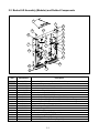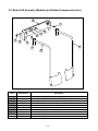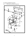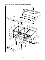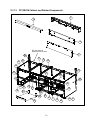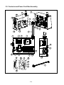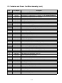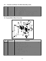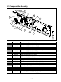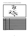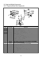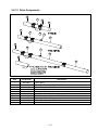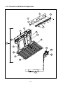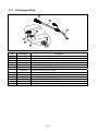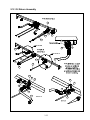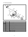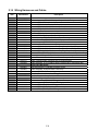
1
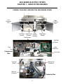
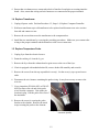
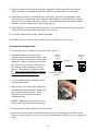
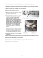
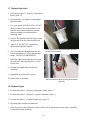
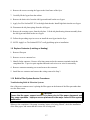
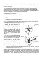
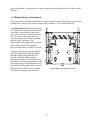
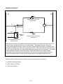
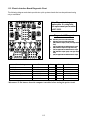
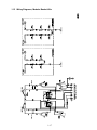
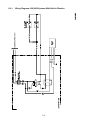
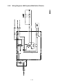
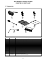
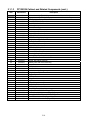
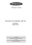
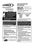
2836 Series Electric Fryers
Service and Parts Manual
This manual is for fryers starting with series AD manufactured starting Fall
2006. This manual makes no references to previous models with rounded
elements and float switches. For parts associated with those fryers, refer to 2836
Series Service and Parts Manual part number 819-6049.
Frymaster Dean, a member of the Commercial Food Equipment Service Association,
recommends using CFESA Certified Technicians.
24-Hour Service Hotline 1-800-551-8633
www.frymaster.com
Email: [email protected]
MAY 2009
*8196114*
NOTICE
IF, DURING THE WARRANTY PERIOD, THE CUSTOMER USES A PART FOR THIS ENODIS
EQUIPMENT OTHER THAN AN UNMODIFIED NEW OR RECYCLED PART PURCHASED DIRECTLY
FROM FRYMASTER DEAN, OR ANY OF ITS AUTHORIZED SERVICE CENTERS, AND/OR THE PART
BEING USED IS MODIFIED FROM ITS ORIGINAL CONFIGURATION, THIS WARRANTY WILL BE VOID.
FURTHER, FRYMASTER DEAN AND ITS AFFILIATES WILL NOT BE LIABLE FOR ANY CLAIMS,
DAMAGES OR EXPENSES INCURRED BY THE CUSTOMER WHICH ARISE DIRECTLY OR
INDIRECTLY, IN WHOLE OR IN PART, DUE TO THE INSTALLATION OF ANY MODIFIED PART
AND/OR PART RECEIVED FROM AN UNAUTHORIZED SERVICE CENTER.
NOTICE
This appliance is intended for professional use only and is to be operated by qualified personnel
only. A Frymaster Dean Factory Authorized Service Center (FASC) or other qualified professional
should perform installation, maintenance, and repairs. Installation, maintenance, or repairs by
unqualified personnel may void the manufacturer’s warranty. See Chapter 1 of this manual for
definitions of qualified personnel.
NOTICE
This equipment must be installed in accordance with the appropriate national and local codes of the
country and/or region in which the appliance is installed.
NOTICE
Drawings and photos used in this manual are intended to illustrate operational, cleaning and
technical procedures and may not conform to onsite management operational procedures.
NOTICE TO OWNERS OF UNITS EQUIPPED WITH COMPUTERS
U.S.
This device complies with Part 15 of the FCC rules. Operation is subject to the following two
conditions: 1) This device may not cause harmful interference, and 2) This device must accept any
interference received, including interference that may cause undesired operation. While this device
is a verified Class A device, it has been shown to meet Class B limits.
CANADA
This digital apparatus does not exceed the Class A or B limits for radio noise emissions as set out
by the ICES-003 standard of the Canadian Department of Communications.
Cet appareil numerique n’emet pas de bruits radioelectriques depassany les limites de classe A et B
prescrites dans la norme NMB-003 edictee par le Ministre des Communications du Canada.
DANGER
Improper installation, adjustment, maintenance or service, and unauthorized alterations or
modifications can cause property damage, injury, or death. Read the installation, operating and
service instructions thoroughly before installing or servicing this equipment.
DANGER
Copper wire suitable for at least 167ºF (75ºC) must be used for power connections.
DANGER
The electrical power supply for this appliance must be the same as indicated on the rating and serial
number plate located on the inside of the fryer door.
DANGER
This appliance must be connected to the voltage and phase as specified on the ratings and serial
number plate located on the inside of the fryer door.
WARNING
Do not attach accessories to this fryer unless the fryer is secured from tipping. Personal injury may
result.
WARNING
Do not use water jets to clean this equipment.
WARNING
This equipment is intended for indoor use only. Do not install or operated this equipment in outdoor
areas.
DANGER
Adequate means must be provided to limit the movement of this appliance without depending on or
transmitting stress to the electrical conduit. A restraint kit is provided with the fryer. If the restraint
kit is missing contact your local Frymaster Dean Factory Authorized Service Center (FASC) for part
number 826-0900.
DANGER
Prior to movement, testing, maintenance and any repair on your Frymaster fryer, disconnect all
electrical power from the fryer.
DANGER
The front ledge of the fryer is not a step. Do not stand on the fryer. Serious injury can result from
slips or contact with the hot oil.
DANGER
Do not store or use gasoline or other flammable vapors and liquids in the vicinity of this or any other
appliance.
DANGER
The crumb tray in fryers equipped with a filter system must be emptied into a fireproof container at
the end of frying operations each day. Some food particles can spontaneously combust if left
soaking in certain shortening material. Additional information can be obtained in the filtration
manual included with the system.
WARNING
No structural material on the fryer should be altered or removed to accommodate placement of the
fryer under a hood. Questions? Call the Frymaster Dean Service Hotline at 1-800-551-8633.
WARNING
Do not bang fry baskets or other utensils on the fryer’s joiner strip. The strip is present to seal the
joint between the frypot. Banging fry baskets on the strip to dislodge shortening will distort the
strip, adversely affecting its fit. It is designed for a tight fit and should only be removed for cleaning.
2836 Series Electric Fryers
Service & Parts Manual
TABLE OF CONTENTS
Page #
1.
SERVICE PROCEDURES
1-1
1.1
General
1-1
1.2
Replace Computer/Controller
1-1
1.3
Replace Interface Board
1-2
1.4
Replace Transformer
1-3
1.5
Replace Temperature Probe
1-3
1.6
Replace Heating Element
1-4
1.7
Replace High-Limit
1-6
1.8
Replace Frypot
1-6
1.9
Replace Contactor (Latching or Heating)
1-7
1.10 Built-in Filter System Service Procedures
1-7
1.11 Basket Lift Service Procedures
1-9
1.12 Electric Interface Board Diagnostic Chart
1-12
1.13 Probe Resistance Chart
1-13
1.14.1 Wiring Diagrams, Main 208/240V
1-14
1.14.2 Wiring Diagrams, Main 480V (120V Controls)
1-15
1.14.3 Wiring Diagrams, Main FP28DV/36 480V (120V Controls)
1-16
1.15 Wiring Diagrams, Modular Basket Lifts
1-17
1.16 Wiring Diagrams, 208/240V Systems With Built-in Filtration
1-18
1.16.1 Wiring Diagrams, 480V Systems With Built-in Filtration
1-19
2836 Series Electric Fryers
Service & Parts Manual
TABLE OF CONTENTS (CONT.)
Page #
2.
PARTS LIST
2-1
2.1
Accessories
2-1
2.2
Basket Lift Assembly (Modular) and Related Components
2-2
2.3
Cabinetry and Related Components
2-5
2.3.1.1
F228 Cabinetry
2-5
2.3.1.2
F128/136 Cabinetry
2-7
2.3.1.3
F128/236 Cabinetry
2-9
2.3.2
Door Components
2-11
2.3.3
Dump Station Components
2-12
2.4
Computer and Related Components
2-13
2.5
Contactor and Power Cord Box Assembly
2-14
2.6
Terminal Block Mount Assembly
2-16
2.7
Component Box Assembly
2-17
2.8
Filter Pan and Related Components
2-19
2.9
Frypot and Related Components
2-20
2.9.1.1
Frypot and Drain Valve Components
2-20
2.9.1.2
Drain Components
2-21
2.10
Elements and Related Components
2-22
2.11
Oil Disposal Wand
2-24
2.12
Oil Return Assembly
2-25
2.13
Filter Pump Assembly
2-27
2.14
Wiring Harnesses and Cables
2-28
2836 SERIES ELECTRIC FRYERS
CHAPTER 1: SERVICE PROCEDURES
FINDING YOUR WAY AROUND THE 2836 SERIES FRYER
Left
Contactor
Box
Right
Contactor
Box
Filter
Left Drain Under Fryer
Control
Handle
Filtration
Handles
Transformers
Right Drain
Handle
Interface
Board
Fuse
Wire
Harness
Component
Box
Controller
Terminal
Block
Mechanical
Contactor
Mercury
Contactor
Contactor Box
1-1
1.1 General
Before performing any maintenance on your Frymaster Dean 2836 Series Electric fryer, you must
disconnect the electrical power supply.
When electrical wires are disconnected, it is recommended that they be marked in such a way as to
facilitate reassembly.
DANGER
Hot oil will cause severe burns. Never attempt to move this appliance when filled with hot
oil, or to transfer hot oil from one container to another.
DANGER
This equipment should be unplugged when servicing, except when electrical circuit tests are
required. Use extreme care when performing such tests.
This appliance may have more than one electrical power supply connection point.
Disconnect all power cords before servicing.
Inspection, testing and repair of electrical components should be performed by an
authorized service agent only.
1.2 Replace Computer/Controller
1. Unscrew and remove two control panel screws on control panel front. Swing the panel open
from the top.
2. Unplug wiring harness at plug on back of controller. Unplug controller ground wire from
controller.
3. Remove the control panel/controller by lifting the assembly from the hinged slots in the controlpanel frame.
4. Reverse procedures to install new controller.
1.3 Replace Interface Board
1. Unplug all power cords. Perform Procedure 1.2, Steps 1-4, Replace Computer/Controller.
2. Unplug wire harness from the interface board. Remove all wiring from the terminals of the
interface board, ensuring that each wire is marked for reattachment.
3. Remove the nuts from each corner of the interface board and slide the board from the studs.
Unplug connectors J1 and J2, mark and unplug all other wiring on rear of the interface board.
Ensure that standoffs remain in place on studs prior to installing new interface board. Install the
new interface board by reversing the previous procedures.
1-2
4. Ensure that wire harnesses are connected to back of interface board prior to securing interface
board. Also, ensure that wiring and wire harnesses are connected to the proper terminals.
1.4 Replace Transformer
1. Unplug all power cords. Perform Procedure 1.2, Steps 1-4, Replace Computer/Controller.
2. Hold new transformer up to old transformer to be replaced and disconnect one wire at a time
from old and connect to new.
3. Remove the screws that secure the transformer to the component box.
4. Install the new transformer by reversing the preceding procedures. Make sure you reconnect the
wiring to the proper terminals and the harnesses to the correct connectors.
1.5 Replace Temperature Probe
1. Unplug fryer from the electrical source.
2. Drain the cooking oil from the frypot.
3. Remove the fryer from the exhaust hood to gain access to the rear of the fryer.
4. If unit is equipped with modular basket lift, remove basket lift assembly and set aside.
5. Remove the screws from the top cap and back cover(s). Set the cover(s), top cap and screws
aside.
6. Disconnect the wire harness containing the probe wiring. It may be necessary to remove the
wire ties.
7. Use a pin-pusher (P/N 806-4855 or P/N 8070928) to remove the red and white probe
wires from the connector. Note probe pin
location in plug. Pull the probe wires out of
the insulation.
8. Remove the screw(s) securing the probe
bracket to the element. Remove the metal
wraps securing the probe to the element.
Use a pin-pusher to remove probe wires from
connector (arrows).
1-3
9. Remove the probe bracket and the securing components from the probe bulb and element.
Thread the probe wire through the hole in the tilt plate assembly and remove the probe.
10. Thread the new probe wire through the hole in tilt plate. Place the new temperature probe
assembly onto the element and secure with the bracket and screws removed earlier. Clip the
probe onto the rear of the element in two places. The temperature probe assembly should be
oriented in the same manner as the probe being replaced.
11. Thread the probe wires into the harness insulation. Note the pin positions and insert pins in the
connector. Reconnect the harness and secure with a wire-tie.
12. Lower the element into the frypot with the lift handle.
13. Install the back covers, basket lift assembly, and top cap and secure with screws.
1.6 Replace Heating Element
1. Perform Procedure 1.5, Replace Temperature Probe, Steps 1-7.
2. Unplug the element connectors for the
element being removed (right element- 6-pin
harness connector; left element- 9-pin harness
connector). Remove the element wires from
the connector. Press down on either side of
the connector while pulling up on the top
portion. The connector will open from the
top. Note wiring configuration in connector
before removing element wire pins. Pull all
wires from the connector.
Harness
Connector
Closed
Harness
Connector
Open
Top Portion
Push in on tabs to release
top portion
3. Loosen conduit connector and pull element
wires through conduit.
4. Remove the screws securing the temperature
probe bracket from the element. Remove the
probe clamp (metal wire-wrap). Set the
temperature probe and probe-securing
components aside.
Loosen connector here.
NOTE: Temperature probe removal is not
required if the left element is being replaced.
5. Disconnect the element springs from the tilt brackets.
6. Remove the element clamps and hardware before removing mounting-screws and nuts on the
defective element. Remove all wire-ties securing element wiring, and then remove element from
frypot.
1-4
7. Install the replacement element in the frypot and secure with the mounting hardware.
8. Reinstall the temperature probe and probe-bracket components onto the replacement element.
9. Route the element leads (terminals) to the rear of the fryer
10. Secure element wiring with wire-ties.
11. Route the element wires through the conduit
and tighten conduit connector.
11. When replacing the left element (as viewed
from the rear of the fryer), use the 9-pin
connector, inserting the leads from the
replacement element. Ensure the pin
numbers match the numbers of the defective
element wires. When all pin terminals have
been fully inserted, close the connector by
sliding the halves together until the tabs snap
back into place (reverse procedure in this
section, Step 2). Check wire numbers to
ensure correct wiring of the replacement
element.
Ensure that the wires are properly routed and
secured.
When replacing the right element (as viewed
from the rear of the fryer), follow the above
procedure, inserting pin terminals into the
corresponding holes in the 6-pin connector.
Left Element—
9-Pin Connector
Right Element—
6-Pin Connector
12. Connect the connectors, ensuring the latches
lock in place.
13. Install the temperature probe wires (marked for re-assembly) in the corresponding pin locations.
14. Reconnect the element springs to the tilt brackets
15. Install the back covers, basket lift assembly, and top cap and secure with screws.
16. Position fryer under exhaust hood.
1-5
1.7 Replace High-Limit
1. Perform Procedure 1.5, Replace Temperature
Probe, Steps 1-4.
2. Disconnect the wire harness containing the
high-limit wires.
3. Use a pin-pusher (P/N 806-4855 or P/N 8070928) to remove the two high-limit wires
from the wire harness connector (arrows).
Note pin location in connector before
removing wires.
4. Remove the high-limit from the frypot using
an open-end wrench or other suitable tool.
5. Apply Loc-Tite PST 567 sealant to the
replacement high-limit threads.
Using a pin-pusher, remove two high-limit wires
(arrows) from connector.
6. Screw the replacement high-limit into the
frypot and tighten to 170-180 inch-pounds
torque. DO NOT OVERTIGHTEN.
7. Insert the replacement high-limit wires into
the connector, ensuring each wire is in the
correct hole..
8. Reconnect the high-limit wire-harness
connector.
9. Install and secure the back cover(s).
10. Return fryer to operation.
Place wrench here when removing and installing
high-limit.
1.8 Replace Frypot
1. Perform Procedure 1.5, Replace Temperature Probe, Steps 1-7.
2. Perform Procedure 1.2, Replace Computer/Controller, Steps 1-3.
3. Perform Procedure 1.7, Replace High-Limit, Steps 1-4.
4. Disconnect the element wire harnesses.
5. If the fryer has a built-in filtration system, remove all the plumbing from the frypot, including
oil-return and drain plumbing.
1-6
6. Remove the screws securing the frypot to the front frame of the fryer.
7. Carefully lift the frypot from the cabinet.
8. Remove the drain valve from the old frypot and install on the new frypot.
9. Apply Loc-Tite Sealant PST 567 to the high-limit threads. Install high-limit into the new frypot.
10. Disconnect the tilt plate springs from the old frypot.
11. Remove the securing screws from the tilt plate. Lift the tilt plate/heating element assembly from
the old frypot and install on the new frypot.
12. Follow the preceding steps in reverse to install the new frypot into the fryer.
13. NOTE: Apply Loc-Tite Sealant PST 567 to all pipefittings prior to installation.
1.9 Replace Contactor (Latching or Heating)
1. Remove filter pan.
2. Remove cover to contactor box.
3. Identify faulty contactor. Remove all wiring connected to the contactor terminals inside the
component box. Tape wire-pairs together and mark each wire-set or wire for reassembly.
4. Remove contactor-mounting screws and remove the contactor.
5. Install the new contactor and connect the wiring removed in Step 3.
1.10 Built-in Filter System Service Procedures
Troubleshooting Built-In Filtration Systems
One of the most common errors is placing the filter paper on the bottom of the filter pan rather than
over the filter screen.
CAUTION
Ensure that the paper support screen is in place prior to filter paper placement and
filter pump operation. Improper screen placement is the major cause of filter system
malfunction.
Whenever the complaint is "the pump is running, but no oil is being filtered", check the installation
of the filter paper, and ensure that the correct size is being used.
1-7
If the pump motor overheats, a circuit breaker will trip and the motor will not start until the breaker
is reset. If the pump motor does not start, press the white reset button located under the component
box, inside the cabinet.
If the pump starts after resetting the breaker, then something is causing the motor to overheat. A
major cause of overheating is when several frypots are filtered sequentially, thus overheating the
pump and motor. Allow the pump motor to cool at least 30 minutes before resuming operation, and
allow time for the motor to cool between sequential frypot filtering.
Pump overheating can be caused by:
•
Solidified shortening in the pan or filter lines,
or
•
Attempting to filter unheated oil or shortening.
Cold oil and shortening are more viscous, causing the pump motor to overheat. Always filter with
the oil or shortening at operating temperature [350°F (177°C)].
If the motor runs but the pump does not,
there is a blockage in the pump. Incorrectly
sized or installed paper/pads will allow food
particles and sediment to pass through the
filter pan and into the pump. When sediment
enters the pump, the gears bind, causing the
motor to overload, again tripping the thermal
overload. Solidified shortening in the pump
will also cause it to seize, with the same
problem.
A pump seized by debris or hard shortening
can usually be freed by manually moving the
gears with a screwdriver or other instrument.
Sediment Particle
Oil Flow
Sediment Particle
Disconnect power to the filter system,
remove the input plumbing from the pump,
and use a screwdriver to manually turn the
gears.
Up for reverse
Down for forward
● Turning the pump gears in reverse will
release a hard particle.
● Turning the pump gears forward will push softer objects and solid shortening through the
pump and allow free movement of the gears.
Incorrectly sized or installed paper/pads allows food particles and sediment to pass through and clog
the suction tube on the bottom of the filter pan. Particles large enough to block the suction tube may
indicate that the crumb tray is not being used. Pan blockage can also occur if shortening is left in the
pan and allowed to solidify. Blockage removal can be accomplished by forcing the item out with an
1-8
auger or drain snake. Compressed air or other pressurized gases should not be used to force out the
blockage
1.11 Basket Lift Service Procedures
2836 Series Electric fryers may optionally be equipped with automatic basket lifts to ensure uniform
cooking times. Electric fryers can be equipped with "modular" or "bell-crank" basket lifts.
A modular basket lift (illustrated) consists
of a toothed rod to which the basket lift arm
is attached, a reversible-drive gear motor
and a pair of roller-activated microswitches.
The gear motor engages the teeth of the
rods, moving them up or down, depending
upon the motors’ direction. The
microswitches at the upper and lower limits
of movement stop the motor when the
basket is in the full up or full down position.
Timing circuitry in the controller initiates
and stops basket lift operation depending
upon the variables programmed by the
operator. When the product button is
pressed, the timing circuitry activates a coil
in the basket lift relay to supply power to the
lower microswitch. The microswitches stop
the motor at the lift’s upper and lower travel
limits and reverse the direction of current
flow, thus reversing the motor direction.
Modular Basket Lift Assembly (Typical).
1-9
Simplified Schematic
H
N
Normally Open Upper-limit
Microswitch
5
M
6
1 or 4
3
Basket Lift
Relay
Normally Closed Lower-limit
Microswitch
To computer/controller via
interface board
When the product button is pushed on the computer/controller, current flows through a coil in the
basket lift relay, causing the lower circuit to be activated. The basket lift lowers, closing the
normally open upper-microswitch. When the lower normally closed microswitch is opened by the
downward moving lift rod, power to the motor ceases to flow. When the computer/controller timesout, the current to the relay coil is interrupted, allowing the upper circuit to be activated. The basket
lift then raises and closes the lower microswitch. When the basket lift rod clears the upper
microswitch, the microswitch opens, and power to the circuit is interrupted, stopping the motor.
Pushing the product button or activating the manual control (if equipped) restarts the cycle.
Problems with the modular basket lift design can be grouped into three categories:
● Binding/jamming problems
● Motor and gear problems
● Electronics problems
1-10
BINDING/JAMMING PROBLEMS
Noisy, jerky or erratic movement of the lifts is usually due to lack of lubrication of the rods and their
bushings. Apply a light coat of Lubriplate or similar lightweight white grease to the rod and
bushings to correct the problem.
With the modular basket lift, another possible cause of binding is improper positioning of the motor,
which prevents the gear from correctly engaging the teeth in the rod. To correct the problem, loosen
the screws that hold the motor in place and move it forward or backward until the rod has just
enough slack to be rotated slightly.
MOTOR AND GEAR PROBLEMS
With the modular basket lift, the most likely problem to be encountered in this category is erratic
motion of the lift due to a worn drive gear. Failure to keep the lift rod and bushings properly
lubricated will cause unnecessary wear of the gear. The problem is corrected by replacing the worn
gear.
If the lift cycles correctly but fails to remain in the up position (i.e., goes up, but then slowly settles
back down into the frypot), the problem is a failed motor brake. The motor must be replaced.
If power is reaching the motor but the motor fails to run, the motor is burned out and must be
replaced.
ELECTRONICS PROBLEMS
Within this category are problems associated with the relays, microswitches, capacitors, resistors,
interface board, wiring, and controls. The most common problem in this category is a lift that
continuously travels up and down. This is usually caused by a microswitch that is out of adjustment.
Troubleshooting the electronics of a modular-type basket lift is simply a process of verifying current
flow through the individual components up to and including the motor. Using a multimeter set to the
250 VAC range, check the connections on both sides of the component for the presence of the
applied line voltage. The accompanying simplified wiring diagrams identify the components and
wiring connection points.
1-11
1.12 Electric Interface Board Diagnostic Chart
The following diagram and charts provide ten quick system checks that can be performed using
only a multimeter.
Note: The sealed relays are
replaceable. If a relay fails,
the replacement part number
is 807-3932.
K1
3
2
1
6
5
4
9
8
7
12
11
10
15
14
13
K2
Diagnostic LED Legend
K3
CMP
24
HI
K4
HI
HT
HT
AL
10
7
4
1
10
7
4
1
11
8
5
2
11
8
5
2
12
9
6
3
12
9
6
3
Meter Setting
12 VAC Power
24 VAC Power
*Probe Resistance
Hi-Limit Continuity
Latch Contactor Coil
Heat Contactor Coil
AL
Test
50 VAC Scale
50 VAC Scale
R X 1000 OHMS
R X 1 OHMS
R X 1 OHMS
R X 1 OHMS
indicates power from 12V transformer
indicates power from 24V transformer
(RH) indicates output (closed) from right latch
relay
(LH) not applicable to Ultimate Electric fryers
(RH) indicates output from right heat relay
(LH) not applicable to Ultimate Electric fryers
(RH) indicates output (open) from right latch
relay
(LH) not applicable to Ultimate Electric fryers
Pin
1 of J2
2 of J2
11 of J2
7 of J2
8 of J2
9 of J2
Pin
3 of J2
Chassis
12 of J2
4 of J2
Chassis
Chassis
Results
12-16 VAC
24-30 VAC
See Chart
0 - OHMS
3-10 OHMS
18-25 OHMS
*Disconnect 15-Pin harness from the computer/controller before testing the probe circuit.
1-12
1.13 Probe Resistance Chart
Use the chart below when testing temperature probes and probe circuits for proper operation.
Probe Resistance Chart
F
60
65
70
75
80
85
90
95
100
105
110
115
120
125
OHMS
1059
1070
1080
1091
1101
1112
1122
1133
1143
1154
1164
1174
1185
1195
C
16
18
21
24
27
29
32
35
38
41
43
46
49
52
F
130
135
140
145
150
155
160
165
170
175
180
185
190
195
OHMS
1204
1216
1226
1237
1247
1258
1268
1278
1289
1299
1309
1320
1330
1340
C
54
57
60
63
66
68
71
74
77
79
82
85
88
91
F
200
205
210
215
220
225
230
235
240
245
250
255
260
265
OHMS
1350
1361
1371
1381
1391
1402
1412
1422
1432
1442
1453
1463
1473
1483
1-13
C
93
96
99
102
104
107
110
113
116
118
121
124
127
129
F
270
275
280
285
290
295
300
305
310
315
320
325
330
335
OHMS
1493
1503
1514
1524
1534
1544
1554
1564
1574
1584
1594
1604
1614
1624
C
132
135
138
141
143
146
149
152
154
157
160
163
166
168
F
340
345
350
355
360
365
370
375
380
385
390
395
400
405
OHMS
1634
1644
1654
1664
1674
1684
1694
1704
1714
1724
1734
1744
1754
1764
C
171
174
177
179
182
185
188
191
193
196
199
202
204
207
1.14.1 Wiring Diagrams, Main – 208/240V
1-14
1.14.2 Wiring Diagrams, Main 480V (120 V Controls)
1-15
1.14.3 Wiring Diagrams, Main FP28DV/36 480V (120 V Controls)
1-16
1.15 Wiring Diagrams, Modular Basket Lifts
1-17
1.16.1
Wiring Diagrams: 208/240V Systems With Built-in Filtration
1-18
1.16.2
Wiring Diagrams: 480V Systems With Built-in Filtration
1-19
2836 SERIES ELECTRIC FRYERS
CHAPTER 2: PARTS LIST
2.1 Accessories
1
4
2
3
5
6
7
Item
Part Number
1
2
3
4
5
803-0306
826-1118
826-1117
803-0209
803-0348
803-0349
803-0363
803-0350
803-0197
823-4985
823-4961
823-4636
823-5679
803-0293
803-0002
803-0303
6
7
8
*
*
*
*
*
* Not Illustrated
8
Description
Fry Basket, Twin Basket
Caster, 5"- With Brake (Mounting Hardware Included)
Caster, 5"- W/O Brake (Mounting Hardware Included)
Brush, Frypot
Rack, FP36 Basket Support
Rack, FP28 Basket Support
Rack, FP14 (FP28DV) Basket Support
Screen Assembly, FP28/36 Basket
Fryer Friend 27” Cleanout Rod
Splash Guard, Right
Splash Guard, Left
Connecting Strip, FP28/36
Connecting Strip, FP14 (FP28DV)
Glove, Hot Oil Neoprene (pair)
Filter Powder – 80 Individual Packages
Filter Paper –100 sheets
2-1
2.2 Basket Lift Assembly (Modular) and Related Components
4
2
10
18
24
21
3
20
22
8
23
17
9
13
16
11
19
6
7
15
14
5
26
12
25
Item
1
Part Number
106-3775
1
807-0158
2
200-6455
3
806-5964SP
4
806-8530SP
*
106-2770SP
*
106-2771
*
807-2661
*
807-3893
*
807-3893
5
807-1683
6
807-2513
7
807-2572
8
809-0082
9
826-1361
10
809-0127
11
809-0186
12
826-1366
* Not illustrated
Description
Basket Lift, Modular Assembly 100-120V with Relay
Connector, 6-Pin
Mount, Modular Basket Lift
Motor Assembly, Modular 120V Basket Lift
Resistor Assembly, 120V
Resistor Assembly, 200/208/220V
Resistor Assembly, 230/240/250V
Resistor, 13 Ohm -120V, 10W (Part of 806-8530 Assembly)
Resistor, 50 Ohm, 50W (Part of 106-2770: 200-208V Assembly)
Resistor, 50 Ohm, 50W (Part of 106-2771: 230-250V Assembly)
Relay, 12 VDC
Capacitor, Motor Run 12.5 MFD 250 VAC
Microswitch, Formed End
Ring, ¾” Truarc ZP
Screw, 8-32 x 1” Tr Sl HD ZP (Pkg. of 25)
Screw, ¼” – 20 x ½” Rd Sl HD NP
Washer, #8 Lock External Tooth
Nut, 4-40 KEPS Hex w/Ext Tooth (Pkg. of 25)
2-2
2.2 Basket Lift Assembly (Modular) and Related Components (cont.)
13
14
15
16
17
18
19
20
*
21
22
23
24
25
26
*
* Not Illustrated
809-0247
826-1359
826-1371
826-1374
809-0503
810-1012
812-0442
813-0035
826-1385
816-0033
900-5529
902-8499
901-8499
824-1351
824-1353
WIR0597
Nut, 8-32 Hex ZP KEPS
Screw, 4-40 x ¾” Pn Sl Hd Zp (Pkg. of 25)
Screw, Drill #8 x ½” Hx Hd Zp (Pkg. of 25)
Screw, #10 - ½” Hx Washer Hd Np Pkg. of 25)
Screw, 8-32 x ½” Hx Zp
Rod, Modular Basket Lift
Insulation, Safety Drain Box
Bushing, Bronze Bunting .641/.640 ID
Ty Wrap (Pkg. of 25)
Ty Wrap Screw Mount #8 Screw
Gusset, Motor - Modular Basket Lift
Chassis, Right-hand Basket Lift
Chassis, Left-hand Basket Lift
Basket Lift Drip Pan
Basket Lift Drip Pan
Wire Assembly, FP28/36S Mod Bb 120V
2-3
2.2 Basket Lift Assembly (Modular) and Related Components (cont.)
Item
Part Number
1
2
3
4
5
6
7
8
9
106-4312
210-8091
809-0508
809-0190
810-0374
810-0194
809-0990
809-0402
823-5479
823-5480
Description
Roller Assembly FV (Use 106-5958 for DV)
Bracket FV (use 230-0083 for Bracket FP28DV)
Bolt, ¼” - 20 x 1-¼" Hex Head S/S
Washer, Flat- ¼" S/S
Spacer, Tubular Basket Lift Roller
Roller, Basket Lift
Nut, Acorn - ¼” - 20 S/S
Screw, ¼” - 20 x ½” Round Slotted S/S
Basket Lift Arm- Left
Basket Lift Arm- Right
2-4
2.3 Cabinetry and Related Components
2.3.1.1
FP228 Cabinet and Related Components
1
3
2
4
20
10
11
9
21
17
22
19
18
5
14
8
13
16
23
7
15
12 27 28
6
26
24
25
2-5
2.3.1.1
Item
FP228 Cabinet and Related Components (cont.)
Part Number
1
2
3
4
5
6
7
8
9
10
11
12
13
14
15
16
17
18
19
20
21
22
23
24
25
26
27
28
*
*
*
* Not Illustrated
106-3589
106-3751
200-6300
106-3668
200-6301
212-8234
202-6335
200-6108
201-6365
211-8234
200-6009
200-6008
823-4811
823-4810
810-1508
200-6010
200-8233
826-1374
200-6007
106-3698
106-3752
200-6011
106-3753
810-2346
202-6593
823-4679
201-6593
823-4516
200-6376
809-0105
826-1351
826-1376
Description
Cabinet Assembly, FP228
Tilt Housing Assembly, FP228
Upper Back
Top Cap Assembly, FP228
Lower Back
Cabinet Side, Right
Gusset, Right
Cabinet Support, Front
Gusset, Left
Cabinet Side, Left
Cabinet Support, Rear
Cabinet Divider
Hinge, Lower Right
Hinge, Lower Left
Hinge, Upper Universal
Channel, Rear Base Cabinet
Channel, Cabinet Base
Screw, #10 –1/2 Hex Head (Pkg. of 25)
Brace, Front Horizontal Cabinet
Brace Assy, Computer
Upright Assy, LH Rear Enclosure
Bracket, Rear Support
Upright Assy, RH Rear Enclosure
Magnet, Door
Bracket, Filter Pan Cover Mounting, Right
Lid, Filter Pan
Bracket, Filter Pan Cover Mounting, Left
Leg, W/A Channel FP28/36
Plate, FP28/36 Door Hinge Mount
Screw #8 x 3/8” Sltd Hex
Nut Retainer ¼” -20 Nutsert (Pkg. of 10)
Nut KEPS 10-32 HX ZP (Pkg. of 10)
2-6
2.3.1.2
FP128/136 Cabinet and Related Components
1
4
2
3
18
13
14
15
33
16
17
19
20
25
34
21
11
5
22
12
24
23
31
7
8
26 27
6
30
32
2-7
10 28 29
9
2.3.1.2
Item
FP128/136 Cabinet and Related Components (cont.)
Part Number
1
2
3
4
5
6
7
8
9
10
11
12
13
14
15
16
17
18
19
20
21
22
23
24
25
26
27
28
29
30
31
32
*
*
*
*
* Not Illustrated
106-3625
106-3750
200-6298
200-6299
106-3704
212-8234
200-6982
200-6257
200-6109
202-6335
823-4811
201-6335
823-4810
211-8234
200-6096
200-6008
200-6011
106-3753
106-3752
826-1374
106-3698
810-1508
810-2346
200-8233
201-6292
200-6093
200-6090
200-6094
200-6376
823-4516
202-6593
201-6593
823-4679
809-0105
826-1351
826-1376
200-6371
Description
Cabinet Assembly FP128/136
Tilt Housing Assembly, FP128/136
Upper Back Cabinet
Lower Back Cabinet
Top Cap Assembly, FP128/136
Cabinet Side, Right
Lower Cabinet Reinforcement
Cabinet Support, Front
Cabinet Support Front
Gusset Right
Hinge, Lower Right
Gusset, Left
Hinge, Lower Left
Side, Left
Horizontal Cabinet Brace
Cabinet Divider
Bracket, Rear Support
Upright Assy, RH Rear Enclosure
Upright Assy, LH Rear Enclosure
Screw, #10 –1/2 Hex Head (Pkg. of 25)
Brace Assy, Computer
Hinge, Upper Universal
Magnet, Door
Channel, Cabinet Base
Brace, LH Rear Brace Channel
Channel, Rear Base Cabinet
Post, Cabinet Front Vertical
Gusset, Lower Middle Cabinet
Plate, FP28/36 Door Hinge Mount
Leg, W/A Channel FP28/36
Bracket, Filter Pan Cover Mounting, Right
Bracket, Filter Pan Cover Mounting, Left
Lid, Filter Pan
Screw #8 x 3/8 Sltd Hex
Nut Retainer ¼” -20 Nutsert (Pkg. of 10)
Nut KEPS 10-32 HX ZP (Pkg. of 10)
Bracket, FP128/136 Drain Line MTG
2-8
2.3.1.3
FP128/236 Cabinet and Related Components
2
1
3
DV units have an
additional item #5 here.
4
28
27
5
25
6
14
31
12
9
15
13
33
26
35
32 17
19
29
18
23
10
24
20
21
30
2-9
8
7
16
22
34 11
2.1.1.3
Item
FP128/236 Cabinet and Related Components (cont.)
Part Number
1
2
3
4
5
6
7
8
9
10
11
12
13
14
15
16
17
18
19
20
21
22
23
24
25
26
27
28
29
30
31
32
33
34
35
*
*
*
*
*
*
* Not Illustrated
106-3792
106-3811
106-3815
200-6528
200-6529
200-6008
200-6011
200-6090
200-6094
200-6109
200-6257
200-6376
106-3753
200-6493
200-6494
200-6500
200-6292
200-8233
201-6292
201-6335
201-6593
202-6292
202-6335
202-6593
210-6343
211-8234
212-8234
106-3698
106-3752
810-2346
210-6597
810-1508
823-4516
823-4810
823-4811
106-3923
824-1314
200-6377
826-1351
809-0105
826-1376
826-1374
Description
Cabinet Assembly FP128/236 (use 106-5891 for FP128DV/236S)
Topcap Assembly, FP128/236S (use 106-5897 for FP128DV/236S)
Tilt Housing Assembly, FP128/236S
Back, FP128/236S Upper Cabinet
Back, FP128/236S Lower Cabinet
Divider, Cabinet
Bracket, Rear Support
Post, Vertical Cabinet
Gusset, Lower Cabinet Middle
Support, Front Cabinet Cross
Support, Front Cabinet Cross
Plate, Door Hinge Mounting
Upright Assembly, RH Rear Enclosure
Brace, Cabinet Front Horizontal
Brace, Rear Horizontal Cabinet
Support, Front Cabinet Cross
Bar, Lower Cabinet Reinforcement
Channel, Cabinet Base
Brace, LH Rear Base Channel
Gusset, LH Cabinet Channel
Bracket, Filter Pan Cover Mounting
Brace, RH Rear Base Channel
Gusset, RH Cabinet Channel
Bracket, Filter Pan Cover Mounting
Hinge, Door
Side, LH Cabinet
Side, RH Cabinet
Brace Assembly, Computer
Upright Assembly, LH Rear Enclosure
Magnet, Door
Lid, Filter Pan
Hinge, Door Universal
Leg Channel
Hinge, W/A, LH Lower Door
Hinge, W/A RH Lower Door
Channel, Rear Cabinet Base
Plate, Filter Pump Mounting
Bracket, FP128/136S Drain Ling MTG
Nut Retainer, ¼” -20 Nutsert (Pkg. of 10)
Screw, #8 x 3/8” SLTD HX WSHR HD Type F
Nut, KEPS 10-32 HX ZP (Pkg. of 10)
Screw, #10 – ½” Hex Head (Pkg. of 25)
2-10
2.3.2 Door Components
Item
Part Number
1
2
3
4
5
106-3677
106-3676
106-3731
106-4067SP
6
7
8
9
10
200-6176
823-4774
809-0266
826-1343
810-1422
824-1255
824-1270
809-0413
Description
Door Assembly, FP28 Left Door
Door Assembly, FP28 Right Door
Door Assembly, FP36
Pin Assembly, Door Slotted W/Keeper
Liner, Cabinet Door
FP28 Cabinet Door Liner
FP36 Cabinet Door Liner
Screw, #10-1/2 Phil TR HD ZP
Spring, JCF Door Hinge Lock (Pkg. of 10)
Handle, Wireform Door
Door Weldment,
FP28 Cabinet
FP36S Cabinet
Spacer, ¼” X .160 8 Gauge Nylon
2-11
2.3.3 Dump Station Components
1
3
2
4
Item
Part Number
1
2
3
4
813-0396
813-0883
823-4620
812-1699
Description
Drain, Sink 1½” NPS (includes gasket PN 816-0129)
Barb Fitting 1-inch Hose X 1½-inch NPSM
Holder W/A, Dump Station Pan
Hose, 1” ID x 1.405 OD x 16.50”
2-12
2.4 Computer and Related Components
Item
Part Number
1
2
*
3
4
*
*
5
6
7
8
*
*
*
*
* Not Illustrated
106-3840
826-2389
826-2388
106-7177
826-2387
106-3647
106-3587
106-3648
106-3794
200-6037
824-1251
823-4549
823-4689
823-4590
823-4658
106-3669
106-3809
106-3732
106-6213
Description
Computers
Computer, Standard CM3.5
Computer, FP228
FP28 Full Vat
FP28 Dual Vat
FP36 Full Vat
Frame Assembly, FP128S Control Panel
Frame Assembly, FP228S Control Panel
Frame Assembly, FP136 Control Panel
Frame Assembly, FP128/236S Control Panel
Bracket, Center Control Panel
Spacer, Computer Panel
Bezel W/A, FP28 Control Panel Frame
Bezel W/A, FP228 Control Panel Frame
Bezel W/A, FP36S Control Panel Frame
Bezel W/A, FP128/236S Control Panel Frame
Bezel W/A Control Panel Frame with Computer FP28
Bezel W/A Control Panel Frame with Computer FP36
Bezel W/A Control Panel Frame with Computer FP36S
Bezel W/A Control Panel Frame with Computer FP28DV/36S
2-13
2.5 Contactor and Power Cord Box Assembly
2-14
2.5 Contactor and Power Cord Box Assembly (cont.)
Item
Part Number
A
106-4530
106-4531
106-4527
106-4528
807-0159
812-1685
807-0501
106-4089
106-4090
200-6651
200-6652
106-4192
106-4180
200-6809
807-0070
807-0884
810-2866
807-3610
810-0519
809-0247
809-0250
826-1374
807-2240
807-2283
810-1202
826-1363
826-1366
809-0123
809-0104
826-1337
200-8590
200-6648
200-2334
106-3964
200-8030
824-1378
807-1947
809-0360
809-0656
810-1164
816-0217
802-1999
802-1994
802-2248
1
2
3
4
5
6
7
8
9
10
11
12
13
14
15
16
17
18
19
20
21
22
23
24
25
B
26
27
28
29
30
31
32
*
*
*
* Not Illustrated
Description
Box, Assembly, FP28/36S 208/240V LT Contactor
Box, Assembly, FP28/36S 208/240V RT Contactor (Shown in diagram)
Box Assembly, FP28/36S 480V LT Contactor FV (Use 106-5930 FP28DV/36)
Box Assembly, FP28/36S 480V RT Contactor
Connector 12-pin Female
Conduit, Flexible ¾-inch x 8.0-inch
Fuse Block, Buss #2968 3-Pole
Box, FP28/36 LT FV Contactor (Use 106-5813 LT FP28DV/36)
Box, FP28/36 RT Contactor
Cover, Contactor Box LT FV (Use 200-0798 LT FP28DV/36)
Cover, Contactor Box RT
Harness, 208/240V Contactor Box Basket Lift
Harness, 480V Contactor Box Basket Lift
Bracket, Ground Lug Holder
Terminal, Ground Lug
Contactor Mercury 240V 50A
Connector, 1” Screw In Flex
Block, Dean Terminal 1501-AL-9CU
Hinge, Utility
Nut, 8-32 Hex ZP KEPS
Nut, 6-32 Hex ZP KEPS Ea
Screw, #10 – ½” Hex Washer HD NP (Pkg. of 25)
Fuse, 60 AMP 300VAC
Contactor, 63Amp Mechanical 24V Coil (Used on 208/240V)
Contactor, 40 Amp 600V 3 Pole (Used on 480V)
Screw, 8-32 x ½” TR SL HD NP (Pkg. of 25)
Nut, 4-40 KEPS Hex W/External Tooth (Pkg. of 25)
Screw, #10 x ¾” Truss Slotted Head NI
Screw, 8-32 x ½” Truss Slotted Head ZP
Tab, Faston 6.35 [.250] Series (Pkg. of 5)
Plate, Component Box Cable Mtg
Bracket, Contactor Box Fuse Block
Door, Contactor Box
Box Assembly, 120V Power Cord (480V Units Only)
Cover, Electrical Handy Box
Box, FP28/36 120V Power Cord
Plug, .875 Diameter Dome
Screw, #8 X ⅜” Type B HX Washer HD ZP
Screw, 4-40 X ⅜” Rd HD SL NP
Block, 1 Plc Screwless Terminal
Paper, CE Single Terminal Black Insulating
Label, Field Terminal
Label, Use Supply Wiring
Label, 50A Fuse Replacement
2-15
2.5
Contactor and Power Cord Box Assembly (cont.)
*
*
*
*
*
*
*
*
*
* Not Illustrated
802-2246
802-0742
802-2239
802-1991
802-1989
WIR0607
WIR0598
WIR0690
WIR0688
Label, Caution
Label, (Inside Cabinet) Ground
Label, Terminal Block (N & L1)
Label, Terminal Block (L1, L2, L3)
Label, Reduce Elec. Risk Warning
Wire Assembly, FP28/36S Contactor Box Fuse (Used on 208/240V)
Wire Assembly, FP28/36S Contactor Box (Used on 480V)
Wire Assembly FP28DV Contactor Box (Used on 480V)
Wire Assembly FP28DV Contactor Box (used on 480V)
2.6 Terminal Block Mount Assembly
Item
Part Number
1
2
3
4
5
6
7
8
9
10
11
12
106-4471
200-8525
200-9409
200-9410
807-1043
807-4080
807-4081
809-0185
809-0250
826-1374
810-2866
810-2965
823-4976
Description
Terminal Block Mount Assembly (Use 106-6176 for RH mount Assembly)
Spacer, Terminal Block Mounting
Cover, Terminal Block
Spacer, .250 OD x .035 Wall x .50 Long
Bushing, 1.06 ID
Block, 600v 175A CU / 135A AL 3 Pole Power Terminal
Cover, Plastic Power Terminal Block
Washer, #10 Flat SAE
Nut, 6-32 KEPS HX ZP
Screw, #10-1/2” Hex Head (Qty. of 25)
Connector, 1” Screw in Flex (Use 807-4325 for 90º connector)
Plug, 1-1/4” : Snap In
Mount W/A, Terminal Block
2-16
2.7 Component Box Assembly
17
14 20
21
10
12
8
3
4
19
5
1
9
13
2
7
6
16
15
18
11
Item
1
2
3
4
5
6
7
8
9
10
11
12
13
14
Part Number
106-3860
106-3588
106-3859
106-3858
106-3857
106-3691
106-3692
106-3795
809-0159
200-6506
806-3660
806-6336
807-3932
807-0670
807-0680
807-0800
807-0979
807-0855
807-0922
807-2278
810-0045
826-1680
826-1365
826-1366
Description
Box Assembly, FP228 208/240V Component
Box Assembly, FP228 480 V Component
Box Assembly, FP28/36S 208/240V LT Component
Box Assembly, FP28/36S 208/240V RT Component
Box Assembly, FP128/236S 208/240V MDL Component
Box Assembly, FP28/36S 480V LT Component (Use 106-5943 FP28DV LT)
Box Assembly, FP28/36S 480V RT Component
Box Assembly, FP128/236S 480V MDL Component
12-Pin connector FM
Plate, Component Box Fuse Cover
Sound Device, High Output
PCB Assembly, Interface (FV) Common Elect
Relay, 12VDC SPDT 12A Sealed
Relay, Midtex DPDT 24V
Transformer 208/240/24V 50/60 20VA (208/240)
Transformer 120V 50/60-24V 50VA (480V)
Transformer 208/240/24VAC 50/60 43VA (208/240)
Transformer 120V 50/60-12V 20VA (480V)
Holder, Buss Fuse HPS
Fuse, 20 Amp
Bushing, Heyco, 875-11 (11/16")
Clamp, Heyco #3327 Nylon Wire (Pkg. of 8)
Screw, 6-32 X ⅜” TR SL HD NP (Pkg. of 25)
Nut, 4-40 KEPS Hex W/Ext Tooth (Pkg. of 25)
2-17
2.7 Component Box Assembly (cont.)
15
16
17
18
19
20
21
*
*
*
*
*
*
* Not Illustrated
809-0250
826-1371
809-0656
809-0963
810-1164
816-0217
200-6506
WIR0609
WIR0610
WIR0611
WIR0601
WIR0599
WIR0600
Nut, 6-32 Hex ZP KEPS
Screw, Drill #8 X ½” Hex HD ZP (Pkg. of 25)
Screw, 4-40 x 3/8” Rd HD SL NP
Standoff, 6-32, ¼” X 2.00” NP
Block, 1 Plc Screwless Terminal
Paper, Insulating Terminal Block CE
Cover, Component Box Hole 480V
Wire Assembly 208/240V LT Component Box
Wire Assembly 208/240V RT Component Box
Wire Assembly 208/240V Filter Control
Wire Assembly 480V Filter Controls
Wire Assembly 480V LT Component Box
Wire Assembly 480V RT Component Box
2-18
2.8 Filter Pan and Related Components - Built-in Filtration
4
3
10
11
9
5
2
1
12
6
7
8
Item
Part Number
1
2
3
4
5
6
7
8
9
10
11
12
*
*
*
* Not Illustrated
106-4290
106-4291
106-4289
810-0487
823-4829
823-4622
200-7196
809-0059
810-2806
810-2805
813-0037
813-0022
813-0165
810-0487
802-2264
802-2257
802-1604
Description
Complete Filter Pan Assembly FPC228
Complete Filter Pan Assembly FPC128/136-236
Pan Assembly, Filter
Quick Disconnect, ½” Male Used on FP28/36 Only
Ring, Hold Down
Tray, Filter Pan Crumb
Screen, FP3 Sana Grid
Nut, Grip ¼” - 20 HX NP
Caster, Swivel W/Brake
Caster, Swivel
Coupling, ½” NPT x 1-1/8” FP228 only
Nipple, ½” x Close NPT BM FP228 only
Elbow, ST ½” x ½” NPT 90° BM FP228 only
Coupling, Male FP228only
Label, Filter Pan Notice
Label, Filter Pan Assembly
Label, Hot Surface
2-19
2.9 Frypot and Related Components
2.9.1.1 Frypot and Drain Valve Components
Item
Part Number
*
106-5916
106-4198
106-4203
823-4815
823-4816
823-5597
813-0165
210-6765
806-8035
826-1374
810-0297
810-1546
810-1668
106-3756
816-0405
210-7077
200-1617
200-5694
200-6345
106-3745
807-2103
826-1366
810-2783
816-0220
816-0544
1
*
2
3
4
5
*
*
6
7
8
9
10
11
12
13
14
15
16
17
18
* Not Illustrated
Description
Frypot Assembly, FP14 (FP28DV) 55lbs (no float switch)
Frypot Assembly, FP28 110 lbs (no float switch)
Frypot Assembly, FP36S 160 lbs (no float switch)
Frypot W/A, Wal-mart FP28FV110# (no float switch)
Frypot W/A, Wal-mart FP36FV 160# (no float switch)
Frypot W/A, Wal-mart FP14 (FP28DV) 55# (no float switch)
EL, ST ½” NPT 90deg BM
Bracket, FP28/36 Lower Spring
Thermostat Assembly, 435° Hi-Limit
Screw, #10- ½ ” Hex Washer HD NP (Pkg. of 25)
Spring Element Lift Blue 110# FP28
Spring Element Lift Green 160# FP36
Adapter, Male 5/8" O.D. X ½”
Valve Assembly, FP28/36 Frypot Drain (Use 106-5917 for FP14 (FP28DV))
Sleeve, Drain Handle Red Plastic
Handle, Drain Valve (Use 230-0892 for FP14 (FP28DV))
Washer, Drain Microswitch K118G
Cover, Switch Drain FPP
Bracket, Drain Valve Mounting
Bracket Assembly
Switch, CE Micro Straight Lever
Nut, 4-40 KEPS HEX w/external Tooth (Pkg. of 25)
Valve, 1½” Full Port Drain
Insulation, RF Switch
O-Ring, Seal
2-20
2.9.1.2 Drain Components
Item
Part Number
1
2
3
4
5
*
6
7
8
9
* Not Illustrated.
823-4846
106-4310
823-4672
816-0625
809-0969
KIT6214
106-4311
813-0525
823-4674
823-4674
Description
3” Drain Dump
3” Drain Tube Assembly, Right Side FPC128/136 (Includes item #7)
3” Drain Tube, Left Side
3” Connecting Sleeve
3” Clamp
Round Drain Boot Kit (includes 2 clamps and 1 boot)
3” Drain Tube Assembly Center FPC128/236 ( includes item #7)
Barb Fitting 1” Pipe to 1” Hose
3” Drain Tube Right Side FPC128/236
3” Drain Tube Dump, FP28DV
2-21
2.10 Elements and Related Components
2-22
2.10
Item
Elements and Related Components (cont.)
Part Number
106-4200
106-4209
1
210-7154
210-7161
2
810-2751
3
826-1330
4
826-1376
5
106-4385
106-4383
106-4384
106-4382
106-4199
106-4208
6
810-3012
7
220-1250
8
807-4060
807-4062
807-4059
807-4061
807-4038
807-4051
9
807-4074
826-2106
807-4073
826-2107
10
810-2916
11
910-5022
12
910-2042
13
210-8261
210-8262
14
823-4901
823-4904
15
807-1570
16
806-6849
17
810-1212
18
816-0214
19
823-5757
823-5755
823-5756
*
816-0480
*
809-0567
*
826-1339
*
809-0250
*
809-0096
* Not Illustrated
Description
Tilt Plate Assembly FP28 (Use 106-5919 for FP28DV)
Tilt Plate Assembly FP36 (shown in diagram)
Tilt Plate FP28 (Use 230-0704 for FP28DV)
Tilt Plate FP36
Hinge, Stainless Steel (Use 810-3020 for FP28DV)
Screw, 10-32 x 3/8” SLTD TR HD SS (Pkg. of 25)
Nut, KEPS 10 – 32 HX ZP (Pkg. of 10)
Element Assembly, FP28 208/220V
Element Assembly, FP36 208/220V
Element Assembly, FP28 240V
Element Springs listed on page 2-20
Element Assembly, FP36 240V
Element Assembly, FP28 480V (Use 106-5918 for FP28DV)
Element Assembly, FP36 480V
Heyco Plastic Bushing, 1”
Element Tilt Drip Pan FP28/38 (Use 220-1252 for FP28DV)
Element, FP28 208/220V
Element, FP36 208/220V
Element, FP28 240V
NOTE: This manual makes no
Element, FP36 240V
references to previous models
Element, FP28 480V
with rounded elements and float
Element, FP36 480V
switches. For parts associated
Probe, FP28 Temperature
with that fryer refer to 2836
Probe Kit, FP28 Temperature
Service and Parts Manual part
Probe, FP36 Temperature
number 819-6049.
Probe Kit, FP36 Temperature
Handle, Element Lift
Bracket, Element Probe
Clamp, Element (Use 230-0917 for FP28DV)
Bracket, FP28 Element Support, Rear (Use 230-0714 for FP28DV)
Bracket, FP36 Element Support, Rear
Bracket, FP28 Element Support, Front (Use 823-5602 for FP28DV)
Bracket, FP36 Element Support, Front
Clip, Switch
Tilt Switch Assembly
Slotted Pin
Bar, Spring Slot Bracket
Bracket Pan Assy., Tilt Plate Spring FP14 (FP28DV)
Bracket Pan Assy., Tilt Plate Spring FP28
Bracket Pan Assy., Tilt Plate Spring FP36
Plug .375 OD Dome
Ty Wrap, Metal
Bushing, .375 X .188 ID (Pkg. of 10)
Nut, Keps- 6-32 Hex
Screw, 6-32 x 5/8”- Binding, Slotted-Head
2-23
2.11
Item
Oil Disposal Wand
Part Number
106-4395SP
1
810-0490
2
810-1471
3
810-1091
*
826-2052
*
826-2053
*
826-2054
4
810-0680
*
809-0417
5
810-0487
6
823-4924
7
200-8284
*
200-8402
* Not Illustrated
Description
Oil Discard Wand Assembly
Quick Disconnect, ½-inch female
Hose
Wand
Oil Return Plumbing Kit FP228
Oil Return Plumbing Kit FP128/136
Oil Return Plumbing Kit FP128/236
T-Handle
Flange Nut - to mount rod and handle
Disconnect, Coupling ½” Male
Nipple with Bracket, ½” NPT x 7.0”
Wand Bracket – FPC128/136 and FPC128/236
Wand Bracket – FPC 228
2-24
2.12 Oil Return Assembly
2-25
2.12 Return Assembly (cont.)
Item
1
2
3
4
5
6
7
8
9
10
11
12
13
14
15
16
17
18
19
20
21
22
23
24
25
26
27
Part Number
106-3758
106-3759
106-3808
106-5944
106-3925
200-6799
200-8133
200-8285
807-2103
809-0196
826-1366
809-0843
809-0885
810-0278
810-0487
810-1057
810-1668
810-1669
810-2756
810-2339
810-2766
813-0022
813-0165
813-0463
813-0541
816-0220
900-2935
810-2845
810-1369
813-0093
813-0003
810-2754
Description
FP228 Oil Return Assembly
FPC128/136 Oil Return Assembly
FPC128/236 Oil Return Assembly
FPC128DV/236 Oil Return Assembly
Bracket, FP28/36 ½" Valve Microswitch
Cover, Safety Switch
Handle, ½" Valve
Plate, FP28/36 Oil Discard Support
Switch, CE Micro Straight Lever
Washer, Flt 3/8” SAE ZP
Nut, 4-40 KEPS Hex W/Ext Tooth (Pkg. of 25)
Cotter Pin Plated
Washer, ⅜” X 1” X .083”
Valve, ½" Ball
Coupling, Male
Flexline 5/8” O.D. x 13.00”
Adaptor, Male 5/8” O.D. x ½”
Adaptor, Female 7/8” O.D. x ½”
Manifold, FP128/136S Oil Return
Manifold, FP128/236S-FP128DV/236S Oil Return
Rod Assy., FP28/36 Oil Return
Nipple, ½” x Close N.P.T. B.M.
Elbow, ST ½” x ½” NPT 90° BM
Plug, ½” Countersink
Nipple, ½” NPT x 25.50 BM
Insulation, RF Switch
Retainer, Nut Oil Return Valve
Rod Assembly, FP28/36 VAND
Flexline 5/8” x 11.50”
Nipple, ½” x 4” NPT BM
Tee, ½” x ½” x ½ BM
Manifold, FP228 Oil Return
2-26
2.13 Filter Pump Assembly
12
6
8
7
1
5
4
9
3
2
10
Item
Part Number
1
826-1756
826-1270
826-1712
809-0194
809-0514
826-1264
816-0093
810-0490
810-1057
810-1471
810-1668
813-0062
813-0087
813-0165
813-0298
2
3
4
5
6
7
8
9
10
11
12
13
11
13
Description
Motor, Kit 208V 50/60Hz
Motor, Kit 230V 50/60Hz
Motor, Kit 115 V 60 Hz
Washer, Flat 5/16”
Cap Screw, 5/16” – 18 HX HD
Pump and Gasket Kit, Viking 4 GPM 2-Piece
Gasket, Pump/Motor
Quick Disconnect ½” Female
Flexline, 5/8" X 13" Long
Hose, Oil Discharge 24"
Adapter, Male 5/8"O.D. X ½ "
Elbow, ½” 90° BM
Nipple, ½” NPT X 1½” BM
Elbow, ST ½” NPT 90° BM
Nipple, ½” NPT X 2.0” BM
2-27
2.14 Wiring Harnesses and Cables
Item
Part Number
106-3776
106-4180
106-4181
106-4193
106-4192
106-3798
106-3800
106-3801
106-3984
106-5952
106-3786
106-3787
106-3789
106-5945
106-3790
106-3791
106-5949
106-3805
106-3806
106-4182
806-2071
106-3802
106-3803
106-3985
106-4539
106-5942
Description
Basket Lift Harnesses
Harness Assembly FP28/36S Modular Basket Lift with Relay
Harness, FP28/36 480V Controller Box to Basket Lift
Harness, FP28/36 480V Basket Lift Conduit
Harness, FPC28/36 208/240V Basket Lift Conduit
Harness, FP28/36 208/240V Controller Box to Basket Lift
Component Box Harnesses
Harness, FP28/36 480V Component Box
Harness, FP28/36S Component Box Adj Jumper
Cable Assembly, FP28/36 120V Controls
Harness Assembly, FP28/36S 208/240V Component Box
Harness Assembly, FP28 DV Component Box
Contactor Box Harnesses
Harness, FP28/36 480V Contactor Box Two-Wire with 15-pin FM
Harness, FP28/36 208/240V Contactor Box Two-Wire with 15-pin FM
Harness, FP28/36 208/240V Contactor Box Five-Wire with 12-pin Male
Harness, FP14 (FP28DV) 480V Contactor Box Two-Wire with 9-pin Male Plug
Contactor to Component Box Harnesses
Cable, FP28/36S 208/240V Contactor Box to Component Box
Cable, FP28/36S 480V Contactor Box to Component Box
Cable Assembly, FP14 (FP28DV) 480V Contactor Box to Component Box
Filter Pump Harnesses
Harness Assembly, FP28/36S Oil Return Switch
Cable Assembly, FP28/36S 480V Filter Pump
Harness, FP28/36 Oil Return Jumper
Interface Board to Controller Wiring Harness
Interface Board to Controller Harness
Tilt Switch/High-Limit/Probe Harnesses
Harness Assembly, FP28/36S Tilt/High-Limit/Probe
Harness Assembly, FP28/36S 480V Tilt/High-Limit/Probe
Harness, FP28/36S 208/240V Tilt/High-Limit/Probe
Harness, FP28/36S Tilt/High-Limit/Probe
Harness, FP14 (FP28DV) 480V Tilt/High-Limit/Probe
2-28
THIS PAGE INTENTIONALLY LEFT BLANK
Shipping Address: 8700 Line Avenue, Shreveport, Louisiana 71106
TEL 1-318-865-1711
PRINTED IN THE UNITED STATES
FAX (Parts) 1-318-219-7140
SERVICE HOTLINE
1-800-551-8633
FAX (Tech Support) 1-318-219-7135
*8196114*
MAY 09