1
Owner’s Manual
Model
Digital Multitrack Recorder
OPTICAL
ACCESS
OL
0
6
12
24
1
2
3
4
5
6
7
8
A SYNC
RECORD TRACK
1
2
START
6
7
8
IN
OUT
EXIT
/ NO
EXECUTE
/ YES
UNDO / REDO
DISP SEL
SETUP
LOCATE
TIME BASE SEL
SCRUB
3
4
5
IN
OUT
END
STORE
EDIT
VARI PITCH
AUTO RTN
AUTO PLAY
AUTO RTN
CLIPBOARD
AUTO PUNCH
PREVIEW
HOLD/
EJECT
PGM SEL
SHIFT
P.EDIT
RECORD
AUTO
PUNCH
LOC MEM
STOP
CLIPBOARD PLAY
LOCATE ABS 0
LOCATE REC END
PLAY
REW
F FWD
JOG
SHUTTLE
8288 429 000
VR800 Owner’s Manual (Safety Instructions)
CAUTION:
CAUTION
TO PREVENT ELECTRIC SHOCK, MATCH WIDE BLADE OF
PLUG TO WIDE SLOT, FULLY INSERT.
RISK OF ELECTRIC SHOCK
DO NOT OPEN
ATTENTION:
POUR EVITER LES CHOCS ELECTRIQUES, INTRODUIRE
LA LAME LA PLUS LARGE DE LA FICHE DANS LA BORNE
CORRESPONDANTE DE LA PRISE ET POUSSER JUSQU'
AU FOND.
CAUTION: TO REDUCE THE RISK OF ELECTRIC SHOCK,
DO NOT REMOVE COVER (OR BACK).
NO USER - SERVICEABLE PARTS INSIDE.
REFER SERVICING TO QUALIFIED SERVICE PERSONNEL.
The lightning flash with arrowhead symbol, within an equilateral
triangle, is intended to alert the user to the presence of uninsulated
"dangerous voltage" within the product's enclosure that may be
of sufficient magnitude to constitute a risk of electric shock to
persons.
"WARNING"
The exclamation point within an equilateral triangle is intended to
alert the user to the presence of important operating and
maintenance (servicing) instructions in the literature
accompanying the appliance.
"TO REDUCE THE RISK OF FIRE OR ELECTRIC SHOCK,
DO NOT EXPOSE THIS APPLIANCE TO RAIN OR
MOISTURE."
9. Heat - The appliance should be situated away from heat sources
SAFETY INSTRUCTIONS
such as radiators, heat registers, stoves, or other appliances
(including amplifiers) that produce heat.
1. Read Instructions - All the safety and operating instructions
should be read before the appliance is operated.
10. Power Sources - The appliance should be connected to a power
supply only of the type described in the operating instructions
2. Retain Instructions - The safety and operating instructions
should be retained for future reference.
or as marked on the appliance.
11. Grounding or Polarization - The precautions that should be taken
3. Heed Warnings - All warnings on the appliance and in the
operating instructions should be adhered to.
so that the grounding or polarization means of an appliance is
not defeated.
4. Follow Instructions - All operating and use instructions should
be followed.
12. Power Cord Protection - Power supply cords should be routed
so that they are not likely to be walked on or pinched by items
5. Water and Moisture - The appliance should not be used near
water - for example, near a bathtub, washbowl, kitchen sink,
placed upon or against them, paying particular attention to cords
at plugs, convenience receptacles, and the point where they
laundry tub, in a wet basement, or near a swimming pool, and
the like.
exit from the appliance.
13. Cleaning - The appliance should be cleaned only as
6. Carts and Stands - The appliance should be used only with a
cart or stand that is recommended by the manufacturer.
recommended by the manufacturer.
14. Nonuse Periods - The power cord of the appliance should be
unplugged from the outlet when left unused for a long period of
time.
15. Object and Liquid Entry - Care should be taken so that objects
do not fall and liquids are not spilled into the enclosure through
openings.
16. Damage Requiring Service - The appliance should be serviced
An appliance and cart combination should be moved with care.
Quick stops, excessive force, and uneven surfaces may cause
the appliance and cart combination to overturn.
by qualified service personnel when:
A. The power supply cord or the plug has been damaged; or
B. Objects have fallen, or liquid has been spilled into the
appliance; or
C. The appliance has been exposed to rain; or
D. The appliance does not appear to operate normally or
exhibits a marked change in performance; or
E. The appliance has been dropped, or the enclosure damaged.
7. Wall or Ceiling Mounting - The appliance should be mounted to
a wall or ceiling only as recommended by the manufacturer.
8. Ventilation - The appliance should be situated so that its location
or position dose not interfere with its proper ventilation.
For example, the appliance should not be situated on a bed,
17. Servicing - The user should not attempt to service the appliance
sofa, rug, or similar surface that may block the ventilation
openings; or, placed in a built-in installation, such as a bookcase
beyond that described in the operating instructions.
All other servicing should be referred to qualified service
or cabinet that may impede the flow of air through the ventilation
openings.
personnel.
2
VR800 Owner’s Manual (Table of Contents)
Table of Contents
Rehearsing manual punch in/out recording.............40
Manual punch in/out Take............................................41
Undo/redo manual punch in/out recording.............42
Introduction.............................................................................5
Main features...........................................................................5
Precautions..................................................................................6
Recording to a Metronome Sound.......................................43
Note on repair..........................................................................6
About copyrights....................................................................6
About damage.........................................................................6
Digital Recording......................................................................45
Digital recording from an external digital device..........45
Digital recording to an external device............................46
Names and Functions...............................................................7
Storing a Locate Point (Edit Point)........................................48
Top panel..................................................................................8
Rear panel..............................................................................14
Side panel...............................................................................15
Display section...................................................................16
Display when the power is turned on...........................16
Preset display.....................................................................16
Display examples for time base selected via
the TIME BASE SEL key..........................................17
Selecting time base using the DISP SEL key.................17
The REMAIN display.........................................................18
Warning message..............................................................19
Storing and editing the locate points
to the memory keys .................................................49
Storing in real-time...........................................................49
Editing and storing locate data......................................50
Editing and storing data..................................................50
Storing and editing LOCATE key.......................................51
Storing in real-time...........................................................51
Editing and storing locate data......................................52
Edit and re-store data that is already stored...............53
Locate Function........................................................................54
Before Starting..........................................................................20
Direct Locate.......................................................................54
Auto Play............................................................................55
Auto Return........................................................................55
Auto Repeat........................................................................56
Time Base.............................................................................20
Recording method and REMAIN indicator...................21
Managing songs by Program Change function............22
Real tracks and Additional tracks.....................................23
Input monitoring and playback monitoring................24
Audio file and event.............................................................25
Cue & Review Function...........................................................57
Cue & Review function using
the REWIND and F FWD button............................57
Cue & Review function using the SHUTTLE feature......57
Digital scrubbing using the SCRUB function..................58
Formatting a Disk.....................................................................27
Recording mode....................................................................27
Formatting the current drive (SCSI disk)........................28
Formatting the current drive (E-IDE hard disk).............30
Formatting a backup disk (SCSI disk)...............................30
Formatting a backup disk (fixed disk).............................31
Preview Function......................................................................59
Executing the Preview function.........................................59
Trimming the sound while previewing...........................60
Handling Programs..................................................................32
Editing Tracks...........................................................................61
Creating a new Program....................................................32
Using a Program Change function....................................33
Deleting a Program...........................................................34
Editing a Program title......................................................35
Copy & Paste and Move & Paste......................................61
Storing the edit points......................................................62
Checking and adjusting the edit points.......................62
Executing Copy (or Move)..............................................62
Checking the clipboard data..........................................62
Executing Paste..................................................................63
Undo/redo Paste...............................................................63
Erase..................................................................................64
Storing the edit points......................................................65
Checking and adjusting the edit points.......................65
Executing Erase..................................................................65
Undo/redo Erase...............................................................65
Track Exchange.................................................................66
Executing Track Exchange..............................................67
Punch In/Out Recording.........................................................36
What is Punch In/Out recording?.....................................36
Auto Punch In/Out...............................................................36
Preparation...................................................................36
Rehearsing auto punch in/out recording...................38
Auto punch in/out Take.................................................39
Undo/redo auto punch in/out recording...................39
Manual Punch In/Out recording......................................40
preparation...................................................................40
3
VR800 Owner’s Manual (Table of Contents)
MIDI Sync function...................................................................68
Explanation on the command/mode list...........................113
MIDI clock sync system....................................................68
MTC sync/MIDI Machine Control system.......................70
External MIDI equipment sync system by the
slave mode................................................................... ..73
The status request command.............................................115
Explanation on the status reply...........................................116
Maintenance/Specifications..............................................118
Saving and Loading Song Data.............................................75
Outline of the save/load operation..................................75
Saving and loading data using a SCSI drive
as the current drive...................................................78
Saving/loading data using another SCSI drive...........78
SCSI drive connection and preparation...............78
Saving data.................................................................79
Loading data...............................................................80
Saving/loading via a DAT or adat.................................81
Saving and loading data using an 3.5-inch
E-IDE hard disk as the current drive......................82
Saving song data via a DAT or adat...............................82
DAT (or adat) connection and preparation........82
Saving data.................................................................83
Loading song data via a DAT or adat............................84
DAT (or adat) connection and preparation........84
Loading data...............................................................85
Saving and loading song data via a SCSI drive............86
Quick Troubleshooting...................................................87
Changing the Initial Settings (SETUP mode)......................88
Selecting SETUP mode.........................................................89
Setting a time signature.......................................................90
Setting a tempo.....................................................................92
Setting the metronome function.......................................93
Setting a preroll value..........................................................94
Setting MIDI sync output signal.........................................95
Setting an MTC frame rate..................................................96
Setting an MTC offset value................................................96
Setting MTC Offset mode....................................................97
Setting the slave mode ........................................................98
Setting the slave type...........................................................99
Setting the Record Protect function...............................100
Setting digital input tracks...............................................101
Setting digital output tracks.............................................102
Setting BAR/BEAT resolution mode...............................103
Setting the MIDI device number.....................................104
Checking the number of each track events..................105
MIDI Implementation Chart..................................................106
MMC Command List/Inquiry Message List....................107
Fostex System Exclusive Message...................................108
Status Request.......................................................................109
Data Type.................................................................................111
4
VR800 Owner’s Manual (Introduction/Main features/Precautions)
• An “Undo/Redo function” enables you to easily correct
recording and editing mistakes.
Introduction
Thank you for purchasing the Fostex Model VR800.
The VR800 is a 8-track digital multitrack recorder with
sixteen additional tracks that employs a 3.5-inch E-IDE
type removable hard disk, or external SCSI device
(removable or fixed) as the recording media, instead of
conventional type.
• A “Vari Pitch function” allows you to fine-tune the pitch.
• The VR800 has a “digital input track setup” function that
enables you to input S/P DIF or adat digital signals and record
them on any two tracks or all eight tracks.
• The VR800 has a “digital output track setup” function that
enables you to output digital data as S/P DIF or adat digital
signals and record them on an external digital device (DAT,
MD, adat, etc.).
The VR800 is a digital multitrack recorder that is designed
to connect to a digital mixing console using optical cables.
For recording media, it uses 3.5-inch E-IDE hard disks,
• You can also use the DATA IN/OUT jacks to an external DAT
or adat, and to save and load song data (audio data and
SETUP mode settings) to and from the DAT or adat.
removable disks, such as SCSI Zip and MO drive disks, or
fixed disks to provide you with a maximum of eight tracks
of simultaneous recording and playback, along with 16
additional tracks.
• High-speed SCSI Save/Load is also an option by connecting a
non-DAT or adat SCSI backup drive.
The VR800 records uncompressed digital audio using
16-bit linear quantization, and a sampling frequency of
• A maximum of 99 Locate Pointers can be programmed for a
LOCATE only feature. Simply select the LOCATE number
desired for swift location.
44.1kHz, which enables you to configure a completely
digital recording system that combines various digital
• MIDI clock and Song Position Pointer can be transmitted
according to the internal programmable Tempo Map.
You can set up a synchronization system with a sequencer or
a rhythm machine without wasting a track.
mixers. Adopting A.D.A.C (*) has expanded the disk
recording capacity by a factor of four. You can select
one of three recording modes, depending on the
recording media and application.
You can back up data to DAT tapes or to an adat using a
special adat back-up function. SCSI ports permit fast back-
• You can use the VR800 as a sync slave machine by sending
MTC from a connected device.
up.
• The VR800 supports MTC, MMC, and Fostex System Exclusive
Message, which allows for advanced control and highprecision synchronization from external sequencing software.
You can set the device number and MTC frame rate for MMC
and Fostex System Exclusive Message. Also, “MTC Offset
function” and “Offset Mode function” are useful for setting
up a sync environment using an external sequencing software.
Using an optional Model VC-8 (adat-analog converter)
allows you to connect an analog mixer to the VR800.
Please read this Owner’s Manual and the Quick Operation
Guide.
• Auto Punch In/Out and Manual Punch In/Out functions offer
two modes: “Take” for a real recording, and “Rehearsal” for
monitoring the part between the in and out points.
• The “Program Select function” enables you to select a song
from up to 99 songs and name the songs.
Main features
The VR800’s recorder section uses a recording format
• A “Bar/Beat Resolution function” is used to edit audio at the
beginning of the beat (round up or round off to a beat).
called FDMS-3 (Fostex Disk Management System-3). It
uses an 3.5-inch E-IDE hard disk, external SCSI device
• The “Metronome function” can be used as a rhythm guide
for recording.
(stationary disk or removable disk) as the recording
media.
• Various edit functions using an edit point (locate point), such
as Copy & Paste, Move & Paste, Erase, Auto Punch In/Out,
Auto Locate, are available. You can also locate ABS 0 or REC
END regardless of the edit point (locate point).
• The VR800 features a 3.5-inch bay for easy installation of a
3.5-inch E-IDE hard disk. A SCSI connector enables you to
connect a SCSI device (removable or fixed) as the current or
back-up drive.
• You can set a preroll time of 0 to 10 seconds.
• The VR800 features non-destructive audio editing (a great
advantage of digital recording) such as Copy & Paste, Move
& Paste, Erase, etc. You can choose Time Base (ABS or MTC)
or MIDI bar/beat/clock as the unit.
• A “Disk Remain Display function” offers a clear indication
of available recording time and disk space (in mono track
recording). You can choose the Time Base from ABS, MTC,
and BAR/BEAT/CLK.
• A “Preview function” allows for an intuitive fine-adjustment
of an editing point (locate point).
5
VR800 Owner’s Manual (Introduction/Main features/Precautions)
• If you move the unit from a place with an excessively low
temperature to a warm place, or if you use the unit in a room
in which the temperature varies significantly during winter,
condensation may occur on the hard disk or other parts. In
such cases, leave the unit for about an hour in the new location
before you turn on the power.
Precautions
• Be sure to connect the VR800 to the power supply specified
in the Specifications section of this Owner’s Manual. Do not
use an AC outlet of any other voltage.
• Do not connect the VR800 to the same AC outlet to which
devices that could generate noise (such as a large motor or
dimmer), or the devices that consume a large amount of
power (such as an air conditioning system or large electric
heater) are connected.
Note on repair
• This unit does not use any parts that users can repair easily.
Contact your dealer or the nearest FOSTEX service station to
ask about repairs.
• If you use the unit in an area with a different power voltage,
first consult your dealer or the nearest FOSTEX service station.
You can use the unit with a power frequency of 50Hz or
60Hz.
• Use the packing carton designed for the VR800 when you
transport the unit to the dealer for repair or return.
If you have discarded the packing box, try to pack the unit
completely using shock absorbing materials. Fostex is not
responsible for malfunction or damage due to incomplete
packaging or caused during transport.
• It is very dangerous to use a power cord that is frayed or
damage. In such a case, stop using the unit immediately and
ask your dealer to repair the cord.
• To avoid possible electric shock and damage to the VR800,
avoid contact with water or other liquids, or do not handle
the power plug while your hands are wet.
About copyrights
• It is prohibited by law to use any part of a CD recording or
video images or audio data for which copyright is possessed
by a third party for commercial purposes such as contents,
broadcasts, sales, or distribution- any purpose other than
for your personal pleasure.
• To prevent possible electric shock and damage to the VR800,
do not remove the main unit cover or reach the inside the
unit.
• Do not let water or other liquid, or metal objects such as
pins, accidentally enter the inside of the unit because this
may lead to electric shock or damage. Should water enter
the inside of the unit, remove the power plug from the AC
outlet, and consult your dealer or the nearest FOSTEX service
station.
About damage
• FOSTEX is not responsible for any “direct damage” or
“indirect damage” caused by using the VR800.
• To prevent damage to the VR800, be sure to power on the
connected devices first, then turn on the power to the VR800.
• Before turning the power off to the VR800, first quit Setup
mode and make sure that the recorder section is stopped.
Especially, never attempt to turn off the power to the unit
while the hard disk is accessing data (the HD ACCESS LED is
lit or flashing). Otherwise, not only will you lose recorded
data, but you may damage to the unit.
FOSTEX is not responsible for the data lost during operation
of the unit.
• Before you change the location of the VR800, pack the unit
in the shipping carton or an impact-resistant case.
Make sure that the unit is kept free from external vibration
or impact since the unit is very sensitive to vibration.
• Do not install the unit in locations subject to the following:
* Extremely high or low temperature, or significant changes
in temperature.
* Excessive humidity or dust.
* Excessive changes in power supply voltage
* Unstable or significantly vibrating or shaking surfaces.
* Near a strong magnetic field (such as a TV or speaker).
6
VR800 Owner’s Manual (Names and Functions)
Names and Functions
Rear panel
SCSI
DATA
OUT
IN
OPTICAL
MIDI
OUT
IN
AC IN
POWER
Top panel
Side panel
OPTICAL
PUNCH
IN/OUT
WORD OUT
ACCESS
OL
0
6
12
24
1
2
3
4
5
6
7
8
A SYNC
RECORD TRACK
1
2
START
6
7
8
IN
OUT
EXIT
/ NO
EXECUTE
/ YES
UNDO / REDO
DISP SEL
SETUP
LOCATE
TIME BASE SEL
SCRUB
3
4
5
IN
OUT
END
STORE
EDIT
VARI PITCH
AUTO RTN
AUTO PLAY
AUTO RTN
CLIPBOARD
AUTO PUNCH
PREVIEW
HOLD/
EJECT
PGM SEL
SHIFT
P.EDIT
RECORD
AUTO
PUNCH
JOG
SHUTTLE
LOC MEM
STOP
PLAY
REW
F FWD
CLIPBOARD PLAY
LOCATE ABS 0
LOCATE REC END
7
VR800 Owner’s Manual (Names and Functions)
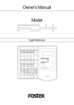
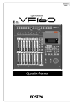
Top Panel Letters in brackets ([
2
]) are labels on the panel.
3
4
OPTICAL
ACCESS
OL
0
6
12
24
1
2
3
4
5
6
7
8
A SYNC
1
RECORD TRACK
30
29
28
27
1
2
START
6
7
IN
OUT
EXIT
/ NO
UNDO / REDO
DISP SEL
SETUP
LOCATE
TIME BASE SEL
SCRUB
3
4
5
IN
OUT
END
STORE
EDIT
VARI PITCH
AUTO RTN
AUTO PLAY
AUTO RTN
CLIPBOARD
AUTO PUNCH
PREVIEW
HOLD/
26
8
EXECUTE
/ YES
EJECT
PGM SEL
JOG
SHUTTLE
25
SHIFT
P.EDIT
RECORD
AUTO
PUNCH
11
LOC MEM
STOP
PLAY
5
6
7
8
9
10
REW
F FWD
12
CLIPBOARD PLAY
LOCATE ABS 0
LOCATE REC END
13
19
18 17 16 15 14
24 23 22 21 20
1. Record track select keys [RECORD TRACK (1 - 8)]
Refer to page 24 for more information on playback monitoring
and input monitoring.
These keys enable you to select SAFE or READY for a
recording track. Pressing the key once will cause the
corresponding track to enter the READY mode, and the lamp
of the key you pressed to flash. Pressing the key again will
cause the corresponding track to enter the SAFE mode, and
the lamp to turn off. When you start recording on a track
in READY mode, the flashing lamp remain lit.
If you press only the RECORD button with a track in READY
mode, you can monitor the signal input to the READY track
so that you can adjust the recording level. To cancel this
input monitoring status, press the RECORD button again.
This puts the VR800 in playback monitoring mode.
You can also use these select keys to select tracks to Copy &
Paste, Move & Paste, Erase and other editing features, as
well as to execute the digital scrubbing.
2. Access LED [ACCESS]
This LED light up or flashes when data is being written to or
read from an external SCSI current drive disk, or 3.5-inch
internal E-IDE hard disk.
Note: Do not turn off the power to the VR800 when this
LED lights up or flashes. Otherwise you may lose data on
the hard disk connected to the VR800.
3.LCD
The LCD indicates signal levels and various settings.
Note: You can record on real tracks 1–8 in real-time, but
not on additional tracks 9–24. If you are using an MO drive
as the current drive, you can record only two tracks
simultaneously. If you try to record more than two tracks by
setting them to READY mode, [Track Over !] appears and
READY mode will cancel.
Refer to “Display Section” on page 16 for more information
on the display.
8
VR800 Owner’s Manual (Names and Functions)
4.Contrast adjustment knob
8. Execute/Yes key [EXECUTE/YES]
Use this knob to adjust the contrast of the LCD. Turning
this knob clockwise will increase the contrast, and turning
Press this key to confirm the edit operations, such as Copy
& Paste, Move & Paste, and Erase, and to set the parameters
it counter-clockwise will decrease the contrast.
of SETUP menus.
Note: The display is not unreadable if you leave the knob
9.Display indication select key [DISP SEL]
counter-clockwise all the way.
Pressing this key each time will change the display indication
as follows:
Currently-selected Time Base indication *1
5.Clipboard In key [CLIPBOARD IN/ PREVIEW ]
Use this key to store the start point of audio data to be
copied or moved. When you press this key, the VR800
Currently-selected Time Base REMAIN indication *2
displays data currently stored, and you can edit the data.
After editing the data, press the STORE key, then press the
CLIPBOARD IN key to store the edited data in this key. The
External MTC IN indication *3
stored data can be used as locate data.
If you press the CLIPBOARD IN key while holding down the
SHIFT key when the recorder is stopped, you can preview
*1 The current position in terms of time base selected via the TIME
BASE SEL key appears. ABS time, MTC time, or BAR/BEAT/CLK is
used.
the fade-in part at the stored CLIPBOARD IN point.
*2 Available recording time and space on the current SCSI disk will
appear. The time indication uses the currently-selected time base
(ABS, MTC, or BAR/BEAT/CLK). The space indication uses MB
(Megabyte). (The values are based on mono track recording.)
* Refer to page 51 for more information on setting and editing
the locate point.
* Refer to page 61 for more information on the Copy & Paste/
Move & Paste functions.
*3 MTC being input from an external MIDI device to the VR800 appears.
If no MTC is input, the display will show “00H 00M 00S 00F.”
* Refer to page 59 for more information on previewing data
at the CLIPBOARD IN point
10. Setup key [SETUP]
6.Clipboard Out key [CLIPBOARD OUT/ PREVIEW ]
Press this key to set the VR800 in SETUP mode to execute
various menus. This key works only when the VR800 is
Use this key to store the end point of audio data to be copied
or moved. When you press this key, the VR800 displays
stopped.
currently-stored data, which you can edit. After editing the
data, press the STORE key, then press the CLIPBOARD OUT
key to store the edited data in this key. The stored data can
Refer to page 88 for more information on SETUP mode.
be used as locate data.
If you press the CLIPBOARD OUT key while holding down
the SHIFT key when the recorder is stopped, you can preview
11. Undo/Redo key [UNDO/REDO]
the fade-out part at the stored CLIPBOARD OUT point.
If you wish to restore the status prior to editing, recording,
or performing a punch in/out take, press the UNDO/REDO
key. Pressing the UNDO/REDO key again will restore the
* Refer to page 51 for more information on setting and editing
the locate point.
status obtained before you pressed the UNDO/REDO key
* Refer to page 61 for more information on the Copy & Paste/
Move & Paste functions.
the first time.
When you undo the operation, [Undo!] will appear. When
* Refer to page 59 for more information on previewing data
at the CLIPBOARD OUT point
you redo the operation, [Redo!] will appears on the display.
Note: The Undo/Redo function works only when the VR800
7. Exit/No key [EXIT/NO/ EJECT ]
is stopped.
This key is the counterpart of the EXECUTE/YES key.
Press this key to cancel an operation.
Refer to pages 39, 42, 63, 65 and “Quick operation guide” for
more information on the Undo/Redo function.
When you use a removable SCSI disk, pressing this key while
holding down the SHIFT key will eject the disk.
9
VR800 Owner’s Manual (Names and Functions)
12. Edit key [EDIT]
15. Time Base select key [TIME BASE SEL]
Pressing this key enters the VR800 to the menu select mode
for editing tracks, and displays the title of the menu you
Pressing this key repeatedly will switch time base as follows:
ABS time
used last time. Press this key repeatedly or turn the JOG
dial to select a menu. The edit menus appear in the following
order. To execute a desired menu, select the menu, then
BAR/BEAT/CLK
press the EXECUTE/YES key.
To exit selection mode, press the EXIT/NO key.
MTC time
Copy Clip
16. Locate key [LOCATE/ LOC MEM ]
Move Clip
Use this key to start the LOCATE feature.
Pressing this key after a memory key (CLIPBOARD IN/OUT,
Copy Paste (or Move Paste *)
AUTO RTN START/END, AUTO PUNCH IN/OUT) locates the
memory data programmed in each respective key (time
Erase
mode or bar, beat, clock setting).
The data can be programmed by individually setting it with
one of the 99 (01-99) locate numbers of the LOCATE key.
TRK Exchange
Note that the data of locate number 00 is available in
(*) After you execute copy clip, “Copy Paste” appears. After you execute
move clip, “Move Paste” appears.
addition to locate numbers 01-99. The last locate time setting
(bar, beat, clock setting) constantly replaces the data stored
in the LOCATE key as data in locate number 00. Therefore,
* Refer to page 61 for more information on Copy & Paste
and Move & Paste.
it is possible to press this key alone to repeatedly locate the
same point.
* Refer to page 64 for more information on Erase.
Pressing the LOCATE key while holding down the SHIFT key
* Refer to page 66 for more information on Track Exchange.
will cause the VR800 to enter edit mode, in which you can
edit data stored in the LOCATE key.
* Refer to page 54 for more information on the Locate
function.
13. JOG dial [JOG/ SHUTTLE ]
When the VR800 is stopped, use the JOG dial to perform a
* Refer to page 51 for more information on editing data
using the LOCATE key.
jog operation (forward or reverse) for audio scrubbing
without pitch change. You can also use this dial to increase
and decrease the numeric values or input alphabetical
characters in edit mode.
Rotating the JOG dial while holding down the SHIFT key
17.Auto Return/Auto Play mode on/off key
[AUTO RTN/AUTO PLAY]
will enable you to perform the shuttle operation with
Use this key to turn on and off auto return mode, auto play
different speeds ranging from normal speed to 64-times
speed.
mode, and auto repeat mode. Each time you press the key,
the mode will change and the following indication displayed.
Refer to page 57 for more information on the cue/review
function and the shuttle function.
AUTO
Auto Return/Play mode is OFF.
(No indication)
AUTO
Auto Play mode is ON.
(“PLAY” lights up.)
PLAY
14. Scrub key [SCRUB]
Pressing this key causes its lamp to light up as the VR800
will enter the digital scrub mode. At this point, press the
RTN
Auto Return mode is ON.
(“RTN” lights up.)
RTN
Auto Repeat mode is ON.
(Both “PLAY” and “RTN” light up.)
AUTO
desired RECORD TRACK select key to digitally scrub the
selected track playback using the JOG dial.
AUTO
PLAY
Refer to page 58 for more information on Digital Scrub mode.
* Auto Play mode
The VR800 locates a point and starts playing from the locate point.
10
VR800 Owner’s Manual (Names and Functions)
* Auto Return mode
When the AUTO RTN END point is reached while the recorder section is
playing, the VR800 automatically locate the AUTO RTN START point.
This mode is effective only if the AUTO RTN START point and the AUTO
RTN END point have already been specified.
20. Fast forward button [F FWD]
Pressing this button while the VR800 is stopped will start
fast forwarding at low speed at first, then gradually
accelerate to 30-times speed. If you press this button while
the VR800 is playing, cueing (fast forwarding with sound)
starts at three-time speed. Pressing this button while holding
Note: The auto return function is enabled only when the
VR800 is playing. While the VR800 is recording, the VR800
will not locate the START point after it reaches the AUTO
RTN END point.
down the STOP button will activate the “LOCATE REC END”
operation, which will locate the end point of the recording
on the real track in the current program. You can also use
this button to locate an edit point in edit mode.
*Auto Repeat mode
This mode is effective only when auto play mode and auto return mode are
turned on. The VR800 will play the part between the AUTO RTN START
point and the AUTO RTN END point repeatedly. This mode is also effective
only if the AUTO RTN START point and the AUTO RTN END point have
already been specified.
Refer to the “STOP button” section and page 48 for more
information on the “LOCATE REC END” operation.
21. Rewind button [REWIND]
Pressing this button while the VR800 is stopped will start
Refer to page 54 for more information on each mode.
rewinding at low speed at first, and then gradually increase
speed up to 30-times speed. If you press this button while
the VR800 is playing, cueing (rewinding with sound) starts
18.Vari Pitch key [VARI PITCH/ P.EDIT ]
at three-times speed. Pressing this button while holding
This key toggles vari pitch mode on and off. When vari
down the STOP button will activate the “LOCATE ABS 0”
operation, which will locate the beginning of the current
pitch mode is on, the “VARI PITCH” indicator lights up on
the display, and the VR800 plays using the current pitch
program (ABS time: 00m 00s 00f). You can also use this
data. Pressing the VARI PITCH key while holding down the
button to locate an edit point in edit mode.
SHIFT key will cause the VR800 to enter edit mode, in which
you can change pitch data in real-time.
Refer to the “STOP button” section and page 48 for more
information on the “LOCATE ABS 0” operation.
To exit edit mode, press the EXIT/NO key.
Refer to Quick operation guide for more information on
playing with Vari Pitch and editing Vari Pitch data.
22. Play button [PLAY]
Pressing this button causes the recorder section to play back.
19. Shift key [ SHIFT ]
Pressing this button while holding down the RECORD button
when a track is in READY mode will cause the VR800 to
Press a key, button, or turn the dial while holding down the
start recording on the READY track.
SHIFT key to activate the following “shift-invoked” functions.
Pressing only this button during the recording operation
will punch-out (cancel) recording. Pressing this button while
You can audition the data at edit points
(locate points) stored in the memory
keys. (For more information, refer to
“Preview function” on page 59.)
AUTO RTN
IN
OUT
IN
END
OUT
PREVIEW
HOLD/
EXIT
/ NO
EJECT
STORE
EDIT
UNDO / REDO
DISP SEL
SETUP
VARI PITCH
AUTO RTN
AUTO PLAY
LOCATE
TIME BASE SEL
SCRUB
P.EDIT
RECORD
LOC MEM
STOP
AUTO
PUNCH
Auto punch mode
turned on and off.
(Refer to “Punch
In/Out” on page
36.)
* Refer to the “STOP button” section and page 62 for more
information on the “CLIPBOARD PLAY” operation.
EXECUTE
/ YES
PGM SEL
SHIFT
PLAY” operation to start.
CLIPBOARD
AUTO PUNCH
START
holding down the STOP button will cause the “CLIPBOARD
The removable SCSI disk is
ejected. (Refer to “Formatting a
disk” on page 31.)
PLAY
REW
F FWD
CLIPBOARD PLAY
LOCATE ABS 0
LOCATE REC END
You can edit Vari Pitch
data. (Refer to Quick
operation guide for more
information on “Playback
in Vari Pitch mode”.)
JOG
SHUTTLE
* Refer to page 41 for more information on the Punch Out
operation using the PLAY button.
The SHUTTLE
function is
activated. (Refer
to “Cue & review
function using the
SHUTTLE
function” on page
57 for more
information.)
23. Stop button [STOP]
Pressing this button during the playback, recording, fast
forward, or rewind operation will stop the recorder transport
operation. Pressing this button while the VR800 is in SETUP
mode will cause the unit to exit SETUP mode.
Pressing the PLAY, REWIND, or F FWD button while holding
You can edit locate data stored
in the LOCATE key. (Refer to
“Storing an edit point (locate
point)” on page 48 for more
information.
down the STOP button will start the following operations.
If you wish to rehearse the manual Punch In/Out operation
using the foot switch, press the foot switch while holding
down this button to enter the rehearsal mode.
11
VR800 Owner’s Manual (Names and Functions)
PLAY
STOP
25. Store key [STORE]
“CLIPBOARD PLAY” operation starts. (See
below.) . During the operation, the STOP
lamp flashes and the PLAY lamp lights up.
This is the key for registering (storing) the time (or BAR/
BEAT/CLK figures) for ABS or MTC into any memory key or
LOCATE key. The key lamp will be lit when this is pressed
and together with a display of [Press LOC:], the locate
number will blink. When registering time data in a memory
key such as AUTO PUNCH IN, any memory key can be
pressed by ignoring this [Press LOC:] display, when
registering in the LOCATE key, specify any locate number
(01~99) while [Press LOC:] is displayed, then press the
LOCATE key. In either case, the STORE key lamp will be
extinguished simultaneous with the completion of time data
registering, and return to the original time base display.
After pressing this key, if you wish to cancel the store
operation, press the EXIT/NO key, or STOP button.
REW
ABS 0 is located. (See below.)
F FWD
REC END is located. (See below.)
* CLIPBOARD PLAY operation
Press the STORE key, and press the CLIPBOARD IN key.
The CLIPBOARD PLAY operation plays back data on the clipboard. (If the
clipboard does not contain any data, the display shows [Void Data !] and
nothing happens.). During this operation, the display indicates the type of
the data (“Copy Clip” for copy data, and “Move Clip” for move data), and the
duration. The indicator of the copy source or move source track will flash.
This way, you will know which track the currently playing data comes from
and why the data is on the clipboard.
The CLIPBOARD IN point will be stored.
This data can be used as locate data.
Press the STORE key, and press the CLIPBOARD OUT key.
The CLIPBOARD OUT point will be stored.
This data can be used as locate data.
Press the STORE key, and press the AUTO PUNCH IN key.
* ABS 0 locate operation
The AUTO PUNCH IN point will be stored.
This data can be used as locate data.
This operation locates the beginning of the current program (ABS time:
00m 00s 00f).
Press the STORE key, and press the AUTO PUNCH OUT key.
* REC END locate operation
The AUTO PUNCH OUT point will be stored.
This data can be used as locate data.
This operation locates the end of the audio recording (REC END) on the
real track in the current program.
Press the STORE key, and press the AUTO RTN START key.
The AUTO RTN START point will be stored.
This data can be used as locate data.
* Refer to page 54 for more information on these operations.
* Refer to page 40 for more information on the Punch In/
Out operation using a foot switch.
Press the STORE key, and press the AUTO RTN END key.
The AUTO RTN END point will be stored.
This data can be used as locate data.
24. Record button [RECORD/ AUTO PUNCH ]
Specify locate number and press LOCATE key
Pressing the PLAY button while holding down this button
The specified locate number will be stored as locate data.
A maximum 99 locate numbers can be registered.
will start the VR800 recording any READY tracks.
The flashing lamp of the RECORD TRACK select key for the
corresponding READY track will light steadily, and the PLAY
If you press the STORE key and the HOLD/> key
simultaneously while the recorder is stopped, the VR800
will enter the program select mode, in which you can select
a program or set up a new one.
lamp and the RECORD lamp light.
If you press only the RECORD button, a READY real track
enters input monitoring mode (The RECORD lamp flashes.).
At this time, pressing the RECORD button again will cancel
* Refer to page 54 for more information on the Locate function.
* Refer to page 48 for more information on storing edit points
(locate points).
* Refer to page 32 for more information on the Program Select
function.
the input monitoring mode, and the track will return to the
playback monitoring mode.
Pressing the RECORD button while holding down the SHIFT
key will toggle between AUTO PUNCH on and off.
* Refer to page 36 for more information on AUTO PUNCH
mode.
26. Hold/> key [HOLD/>]
Pressing the HOLD/> key while the recorder is operating
will cause the VR800 to capture the time when you pressed
it (or bar/beat/clock value), display it, and then enter edit
mode. (If you press the HOLD/> key while the recorder
section is stopped, the VR800 enter edit mode directly.)
To cancel edit mode, press the STOP button, DISP SEL key,
or the EXIT/NO key.
* Refer to page 24 for more information on input monitoring
and playback monitoring.
12
VR800 Owner’s Manual (Names and Functions)
In edit mode, you can use this key to select a digit of the
value to edit (edit point). You can select a digit which flashes
* Refer to page 48 for more information on setting and editing
the AUTO RTN START point.
on the display) in the following order.
* Refer to page 54 for more information on the Auto Return
and Auto Repeat functions.
ABS or MTC is used as time base:
First, “S” (second) flashes. Each time you press the HOLD/> key,
the flashing characters change in this order: F -> SF -> H -> M-> S.
* Refer to page 59 for more information on previewing data
at the AUTO RTN START point.
BAR/BEAT/CLK is used as time base:
First, “BAR” flashes. Each time you press the HOLD/> key, the
29. Auto Punch In key [AUTO PUNCH IN/ PREVIEW ]
flashing indicator changes in this order: -> CLK -> BAR.
Use this key to store the punch in (recording start) point
for the auto punch In/Out function. The stored data is also
If you press the HOLD/> key and the STORE key simultaneously
while the recorder is stopped, the VR800 will enter the program
select mode, in which you can select a program or set up a new
one.
used as a paste start point (for Copy & Paste, Move & Paste)
and as an erase start point.
When you press this key, the VR800 will display currentlystored data, which you can then edit. After editing the
data, press the STORE key, then the AUTO PUNCH IN key to
* Refer to page 48 for more information on editing memory.
store edited data in this key. The stored data can be used
* Refer to page 32 for more information on the Program
Select function.
as locate data.
If you press the AUTO PUNCH IN key while holding down the
SHIFT key when the recorder is stopped, you can preview the
27. Auto Return End key [AUTO RTN END/ PREVIEW ]
fade-out part at the stored AUTO PUNCH IN point.
Use this key to store the start point (AUTO RTN END point)
* Refer to page 48 for more information on setting and editing
the locate point.
for the auto return function and the auto repeat function.
When you press this key, the VR800 will display currentlystored data, which you can edit. After editing the data, press
the STORE key, then press the AUTO RTN END key to store
* Refer to page 36 for more information on the Auto Punch
In/Out functions.
the edited data in this key. The stored data can be used as
locate data.
* Refer to page 59 for more information on previewing data
at the AUTO PUNCH IN point.
If you press the AUTO RTN END key while holding down
the SHIFT key when the recorder is stopped, you can preview
30. Auto Punch Out key
[AUTO PUNCH OUT/ PREVIEW ]
the fade-out part at the stored AUTO RTN END point.
Use this key to store the punch out (recording end) point
for the auto punch In/Out function. The stored data is also
* Refer to page 48 for more information on setting and
editing the locate point.
used as an erase end point.
* Refer to page 54 for more information on the Auto Return
and Auto Repeat functions.
When you press this key, the VR800 will display currentlystored data, which you can then edit. After editing the data,
press the STORE key, and then the AUTO PUNCH OUT key
* Refer to page 59 for more information on previewing data
at the AUTO RTN END point.
to store the edited data in this key. The stored data can be
used as locate data.
28. Auto Return Start key
[AUTO RTN START/ PREVIEW ]
If you press the AUTO PUNCH OUT key while holding down the
SHIFT key when the recorder is stopped, you can preview the
fade-in part at the stored AUTO PUNCH OUT point.
Use this key to store the start point (AUTO RTN START point)
for the auto return function and the auto repeat function.
* Refer to page 48 for more information on setting and editing
the locate point.
When you press this key, the VR800 displays the currentlystored data, which you can edit. After editing the data, press
the STORE key, then the AUTO RTN START key to store the
* Refer to page 36 for more information on the Auto Punch
In/Out functions.
edited data in this key. The stored data can be used as
* Refer to page 59 for more information on previewing data
at the AUTO PUNCH OUT point.
locate data.
This memory is reset to the factory default value when you
turn off the power to the VR800.
If you press the AUTO RTN START key while holding down
the SHIFT key when the recorder is stopped, you can preview
the fade-in part at the stored AUTO RTN START point.
13
VR800 Owner’s Manual (Names and Functions)
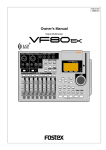
Rear Panel
1
WORD OUT
SCSI
OPTICAL
2 3
4
DATA
OUT
IN
OUT
5
MIDI
6
IN
AC IN
POWER
7
8
1. SCSI connector [SCSI] (Connector: D-SUB 25-pin)
3. Data input jack [DATA IN] (Connector: OPTICAL)
Connect a SCSI device as a current drive or backup device
This is connected to the OPTICAL digital output of the
external digital mixer. This is also connected to the OPTICAL
digital output (or adat out) of any external digital equipment
in use when digitally recording on the VR800 from external
digital equipment (MD, DAT, CD, adat, etc.).
to SAVE/LOAD data. Up to two SCSI devices can be
connected to the SCSI connector. This means the current
drive and backup SCSI equipment can be connected in a
chain.
DATA
IN
SCSI
* Refer to the “Quick Operation Guide” for more information
on connecting the external digital mixer.
* Refer to page 45 for more information on digital recording to
external digital device.
* Refer to page 75 for more information on saving and loading
song data.
* Refer to the “Quick Operation Guide” for information on
connecting an external SCSI drive.
* Refer to page 75 for more details on SAVE/LOAD using a
SCSI device.
2. Data output jack [DATA OUT] (Connector: OPTICAL)
This is connected to the OPTICAL digital input of the external
digital mixer. This is also connected to the OPTICAL digital
input (or adat in) of the external digital equipment in use
when digital recording in external digital equipment (MD,
DAT, CD-R, etc.) from the VR800 or when saving song data
in external DAT or adat.
Note: You can load the data recorded on the current
drive formatted in [Master 8ch] mode and [Master 4ch]
mode from a DAT. You cannot load data recorded in
[ADAC 8ch] mode from a DAT. You can load only the
data recorded on the current drive formatted in [Master
8ch] mode from a adat.
DATA
OUT
4. MIDI OUT jack [MIDI OUT] (Connector: DIN 5-pin)
Connect this jack to the MIDI IN jack of an external MIDI
* Refer to the “Quick Operation Guide” for more information
on connecting the external digital mixer.
* Refer to page 45 for more information on digital recording to
external digital device.
* Refer to page 75 for more information on saving and loading
song data.
device. This jack transmits MTC (MIDI timecode), MIDI clock
& Song Position Pointer, MMC (MIDI Machine Control)
command, response, and FEX (Fostex System Exclusive
Message) response.
MIDI
OUT
Note: You can save the data recorded on the current
drive formatted in [Master 8ch] mode and [Master 4ch]
mode to a DAT. You cannot save data recorded in [ADAC
8ch] mode. You can save only the data recorded on the
current drive formatted in [Master 8ch] mode to a adat.
Refer to page 68 for more information on the example of using
the MIDI OUT jack.
14
VR800 Owner’s Manual (Names and Functions)
5. MIDI IN jack [MIDI IN] (Connector: DIN 5-pin)
7. AC IN connector
Connect this jack to the MIDI OUT jack of an external MIDI
device. You can control the VR800 remotely by inputting
The power cable packaged with this recorder ia connected
here.
MMC (MIDI Machine Control) command or FEX (Fostex
System Exclusive Message) here.
Note: Always plug the power cable to the recorder before
plugging the cable into the wall outlet.
MIDI
IN
8. Power switch [POWER]
This switch turns power on and off to the VR800.
Refer to page 68 for more information on using the MIDI IN
jack.
6. Word Out jack [WORD OUT] (Connector: BNC)
Word clock signal from the VR800 is output here.
This jack and WORD IN of the external digital equipment
must be connected if the WORD IN connector ia provided
in the external digital equipment (digital mixer, etc.) which
is connected to the VR800.
Refer to the separate “Quick Operation Guide” for operating
procedures.
Side Panel
PUNCH
IN/OUT
1. Punch in/out jack [PUNCH IN/OUT] (Connector: phone)
Using an optional foot switch connected to this jack enables
you to perform the manual punch In/Out operation
(including rehearsal) using your foot. Connect an optional
Fostex foot switch, Model 8051.
PUNCH
IN/OUT
Refer to page 40 for more information on using the PUNCH
IN/OUT jack.
Note: Be sure to use an “unlatch type” foot switch if you
use a foot switch other than the Model 8051. Otherwise, a
malfunction could occur.
15
1
VR800 Owner’s Manual (Names and Functions)
Display Section
The VR800 uses a liquid crystal display which integrates a 9-digit/35-dot message section, 7-segment display section, and
level meters. The level meters indicate the output level of tracks 1-8.
The time display shows various information in different units, such as ABS time (absolute time), MTC (MIDI timecode), BAR/
BEAT/CLK (bar/beat/clock), and makes it easy to check the recorder’s current time. The message display shows various
messages required to operate the VR800, and offers interactive operation. This section describes display functions along with
examples.
Display when the power is turned on
Preset display
When you turn on the power to the VR800 and the
connected external SCSI drive (a formatted removable disk
or hard disk), the display shows the [Initial...] message,
[Current Dr], the name of the connected current drive, then
recording mode (Master 8ch, Master 4ch, or ADAC 8ch),
and finally the top position of the disk in the time base
(ABS, MTC, or BAR/BEAT/CLK) used in the last program
before you turned the power off.
The following example indicates that the VR800 started with
the ABS time base used in program 1.
The display below shows all preset items for explanation
purposes.
MTC
DIGITAL
MIDI
SLAVE
44.1kHz
SETUP MTCOFFSET
BAR
CLK
MB
REMAIN ABS
LOC MTC IN
H
M
S
F
VARI PITCH
SURE ?
%
COMPLETED!
SYNC OUT
CLK
MTC
AUTO
PLAY
SF
PGM
TEMPO
RTN
DRIVE
IDE
SCSI
A.PUNCH
RHSL
TAKE
44.1kHz
DIGITAL
The level meter shows the recorder output level and the
recording level for tracks 1~8.
SYNC OUT
DRIVE
AUTO
A.PUNCH
SCSI
When the VR800
recognizes the current
drive, the [SCSI]
indicator lights up in the
[DRIVE] section of the
display if the current
drive is a SCSI device.
The [IDE] indicator
lights up if the current
drive is an E-IDE hard
disk.
DIGITAL
Lights up when ABS is selected as time base.
MTC
Lights up when MTC is selected as time base.
44.1kHz
SYNC OUT
DRIVE
AUTO
A.PUNCH
SCSI
The name of the SCSI drive (The name is
different, depending on the type of device.)
REMAIN
Lights up to indicate available recording time and
space on the disk.
SETUP
Lights up when the VR800 enters SETUP mode.
COMPLETED !
Lights up when an edit operation (copy, move,
paste, or erase) is completed.
SURE ?
Lights up to confirm or cancel the operation when
you are making settings or edits.
MTC OFFSET
Lights up when the MTC Offset menu is selected in
SETUP mode.
PGM
Lights up to indicate the current program number.
TEMPO
Lights up when the tempo setting menu is selected
in SETUP mode.
44.1kHz
DIGITAL
Indicating a recording
mode used during formatting.
ABS
SYNC OUT
DRIVE
AUTO
A.PUNCH
SCSI
VARI PITCH
DIGITAL
Indicating time base
ABS 0 (top of the disk)
44.1kHz
44.1kHz
The VR800 displays the sampling frequency.
If the sampling frequency of the program is different
from the setting for the incoming signal, the indicator
flashes. If the sampling frequency of the incoming
S/P DIF digital signal is different from the setting,
both [DIGITAL] and [44.1kHz] flash.
MTC IN
Lights up to indicate that MTC is input from an
external MIDI device to the VR800.
LOC
Lights up when the VR800 enters locate point (edit
point) edit mode.
ABS
M
S
F
PGM
SYNC OUT
CLK
AUTO
DRIVE
SCSI
A.PUNCH
16
Lights up when vari pitch mode is turned on.
VR800 Owner’s Manual (Names and Functions)
DIGITAL
When you set a digital input track in SETUP mode
and the correct digital signal is input, the indicator
lights up. If the signal is incorrect or the connection
is faulty, the indicator flashes. It also flashes if no
external digital devices are connected to the VR800.
S L AV E
Flashes when slave mode in SETUP mode is turned
on. When a signal is locked, the flashing indicator
lights up steadily.
MIDI
Lights up when the VR800 is receiving effective MIDI
messages (MMC or FEX) from an external device.
Display examples for time base selected via the TIME
BASE SEL key
You can use the TIME BASE SEL key to select ABS, BAR/
BEAT/CLK, or MTC as time base. The following examples
show the displays when you select a time base at the
beginning of the disk of program 1.
Time base is ABS.
DIGITAL
44.1kHz
ABS
M
S
F
PGM
SYNC OUT
CLK
MTC
%
MB
Lights up when the VR800 receives MTC (MIDI Time
Code) from an external device.
DRIVE
SCSI
AUTO
A.PUNCH
Time base is BAR/BEAT/CLK.
Lights up when the VR800 enters vari pitch data
edit mode.
DIGITAL
44.1kHz
BAR
Indicates available disk space on the disk in
megabytes when the REMAIN indicator appears.
CLK
PGM
SYNC OUT
DRIVE
CLK
H, M, S, F, SF
Lights up to indicate a time value when ABS or MTC
is used as time base.
BAR, , CLK
Lights up to indicate a bar/beat/clock value when
BAR/BEAT/CLK is selected as time base.
SCSI
AUTO
A.PUNCH
Time base is MTC.
44.1kHz
DIGITAL
MTC
Indicates a program title, edit parameters, and
SETUP mode parameters.
M
H
S
F
PGM
SYNC OUT
DRIVE
CLK
SCSI
AUTO
SYNC OUT
AUTO
DRIVE
A.PUNCH
A.PUNCH
Indicates the “SYNC OUT settings” in SETUP
mode.
Indicates the AUTO PLAY/AUTO RTN mode
settings.
Selecting time base using the DISP SEL key
The current drive that the VR800 recognizes (SCSI
or ID) appears on the display. (See the following
note.)
When you press the DISP SEL key after you select a time
base using the TIME BASE SEL key, the display changes as
follows:
Indicates the AUTO PUNCH mode settings.
Time base is ABS.
The indicator lights up when the digital-in clock is
set to [ASYnC] (asynchronous). It turns off when
the digital-in clock is set to [SYnC] (synchronous).
The default setting is [ASYnC] (indicator on).
DIGITAL
44.1kHz
ABS
M
S
F
PGM
SYNC OUT
CLK
DRIVE
SCSI
AUTO
Note: If only a SCSI drive is connected to the VR800, [SCSI]
lights up. If an 3.5-inch internal E-IDE hard disk has been
installed but no external SCSI device is connected as the current
drive, [IDE] lights up. If a SCSI drive is connected, turned on,
and specified as the current drive, and an internal hard disk is
also connected, only [SCSI] will light up.
A.PUNCH
44.1kHz
DIGITAL
MB
REMAIN
H
M
S
SYNC OUT
CLK
DRIVE
SCSI
AUTO
DIGITAL
MTC IN
H
M
S
44.1kHz
F
SYNC OUT
CLK
DRIVE
SCSI
AUTO
17
A.PUNCH
A.PUNCH
VR800 Owner’s Manual (Names and Functions)
Time base is BAR/BEAT/CLK.
The REMAIN display
DIGITAL
BAR
The REMAIN display usually shows available recording space
and time on the disk, calculated based on mono track recording.
That is, it indicates how much space and time are available for
recording on a track. Therefore, if you wish to know how much
time is available for multiple-track recording, you need to divide
the REMAIN value by the number of tracks you wish to record.
The value calculation includes all data from real tracks and
additional tracks. If some data exists on the additional tracks,
but not on the real tracks, the space and time consumed by the
additional tracks are considered during the calculation.
For more information on the REMAIN display, please refer to
“Recording method and REMAIN display” in the “Before
Starting” chapter on page 21.
44.1kHz
CLK
PGM
SYNC OUT
DRIVE
CLK
SCSI
AUTO
A.PUNCH
44.1kHz
DIGITAL
BAR
REMAIN
MB
SYNC OUT
DRIVE
CLK
SCSI
AUTO
A.PUNCH
MTC IN
H
S
M
This number indicates available recording
space on the disk for recording on a track.
44.1kHz
DIGITAL
F
SYNC OUT
DRIVE
CLK
SCSI
AUTO
DIGITAL
A.PUNCH
44.1kHz
MB
REMAIN
H
M
S
SYNC OUT
CLK
AUTO
DRIVE
SCSI
A.PUNCH
Time base is MTC.
44.1kHz
DIGITAL
MTC
H
M
S
F
This number indicates available recording time on the
disk for recording on a track. For example, if you record
on eight tracks, one-eighth of the indicated duration is
the available recording time for each track.
PGM
SYNC OUT
DRIVE
CLK
SCSI
AUTO
A.PUNCH
44.1kHz
DIGITAL
MB
REMAIN
H
M
S
SYNC OUT
CLK
DRIVE
SCSI
AUTO
DIGITAL
MTC IN
H
M
S
A.PUNCH
44.1kHz
F
SYNC OUT
CLK
DRIVE
SCSI
AUTO
A.PUNCH
18
VR800 Owner’s Manual (Names and Functions)
Warning messages
The following warnings are shown operating mistakes are made, an unsuitable editing point (= locate point) is input,
or when errors occur. If any of these warnings appear, refer to information detailed below.
<Void Data> message
DIGITAL
SYNC OUT
DRIVE
CLK
SCSI
AUTO
A.PUNCH
SYNC OUT
tracks at a time. After changing the RECORD TRACK select key
setting, please record signals.
<Rec + Yes !> message
DIGITAL
SETUP
DRIVE
SCSI
AUTO
A.PUNCH
A.PUNCH
SURE ?
SYNC OUT
SYNC OUT
CLK
AUTO
Press the EXECUTE/YES key while pressing the RECORD button.
SCSI
SYNC OUT
select key.
SCSI
DRIVE
CLK
SCSI
A.PUNCH
Release the write-protect and re-insert it.
This means there is
insufficient disk space
necessary for recording and
editing.
SYNC OUT
CLK
temporarily data in order to source empty space necessary for
the next operation.
SYNC OUT
DRIVE
SCSI
AUTO
AUTO
A.PUNCH
1. Leave the disk inside the SCSI drive and turn off the power to
the VR800 and all connected devices.
2. Turn on the power to the SCSI drive.
3. Make sure that the orange LED on the SCSI drive lights up in
green and that the disk is not being accessed. Then, turn on
the power to the VR800.
the DATA IN connector and be sure there is no problem with
the DAT, or adat tape. Then, try loading again.
<Unformat !> message
SYNC OUT
DRIVE
AUTO
A.PUNCH
SCSI
procedures.
This means that loading is
impossible because there is
an error in data applied to
the DATA IN connector from
the external DAT, or adat.
Action to take: Check the external DAT or adat connected to
DIGITAL
DRIVE
A.PUNCH
This message indicates that
an error occurs when
accessing the disk. With this
message, no keys and buttons
do not function at all.
Action to take: If this message appears, please use the following
<Load Err > message
CLK
<Acc Error> message
DIGITAL
Action to take: Before proceeding to the next operation,
DIGITAL
A.PUNCH
This means the disk inserted
in the drive cannot be used
because it is write-protected.
The disk will be ejected
automatically.
Action to take:
<Over !> message
DIGITAL
DRIVE
CLK
AUTO
AUTO
<Protected> message
DIGITAL
A.PUNCH
Action to take: Select any one track with the RECORD TRACK
SYNC OUT
A.PUNCH
This is displayed when
formatting. This means press
the EXECUTE/YES key while
pressing the RECORD button.
Action to take:
This means a track has not
been specified.
DRIVE
SCSI
AUTO
<Select Trk> message
44.1kHz
DRIVE
CLK
Action to take: Re-register the correct data.
DIGITAL
This message appears when
trying to record more than 2
tracks of signals
simultaneously using a MO
drive/disk as a Current Drive.
Action to take: The MO drive only allows to record up to 2
This means the registered in/
out point is wrong.
SYNC OUT
SCSI
AUTO
<Void Out !> message
CLK
DRIVE
CLK
Action to take: Re-register the correct data.
DIGITAL
<Track Over> message
DIGITAL
This means registered data
necessary for the selected
operation is incorrect.
An unformatted or crashed
SCSI disk. After a few
seconds of this display, the
VR800 automatically enters
the SETUP mode [Format ?]
menu.
Action to take: Press the EXECUTE/YES key while pressing the
RECORD button.
Note: Any sound data recorded up to this point on the disk
will be lost.
19
VR800 Owner’s Manual (Before Starting)
Before Starting
This chapter describes some basic items that you need to know before you start operating the VR800.
All users, including those who are familiar with using tape-based multitrackers and those who are new to
multitrackers, should read this chapter thoroughly to understand the functions of the VR800.
1. Time Base
2. Recording method and REMAIN indicator
3. Managing songs by Program Change function
4. Real tracks and Additional tracks
5. Input monitoring and playback monitoring
6. Audio file and Event
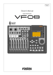
Time Base
The word “Time Base” appears frequently in this manual. The concept of Time Base is similar to a “tape counter”
on a conventional tape-based multitracker in that it indicates the precise position of the recorder transport
section (the current position).
The VR800 offers three types of Time Base: ABS (Absolute type), MTC (MIDI time code), and BAR/BEAT/CLK (bar/
beat/clock). ABS indicates an absolute time on the disk. MTC indicates a relative time that is obtained by adding
a certain value (MTC offset value) to the ABS value. BAR/BEAT/CLK indicates the position in a song created in the
internal Tempo Map according to MIDI clock and Song Position Pointer. The following diagrams depict the
relationship among these three types of the Time Base.
ABS 0
00M, 00S, 00F
00M, 08S, 00F
DISK END
23H, 59M, 59S
REC END
ABS
-002 BAR, 1 , 00 CLK
001 BAR, 1 , 00 CLK
01H, 00M, 00S, 00F
01H, 00M, 08S, 00F
00H, 59M, 52S, 00F
01H, 00M, 00S, 00F
BAR/BEAT/CLK
BAR
= 001BAR, 0404
TEMPO=001BAR, 1 , 60
00H, 59M, 59S
MTC
MTC OFFSET=01H, 00M, 00S, 00F
MTC OFFSET MODE=ABS
(This shall be assumed to be the
MTC OFFSET time set for the ABS
00M, 00S, and 00F positions.)
00H, 59M, 51S
MTC
MTC OFFSET=01H, 00M, 00S, 00F
MTC OFFSET MODE=BAR
(This shall be assumed to be the MTC
OFFSET time set for the 00 BAR, 1
and 00 CLK positions.)
recorded area
non recorded area
Note: As shown in the figure, the ABS 0 position (top of
the disk) is [-2BAR, 1BEAT, 00CLK] (Time Base - BAR/
BEAT/CLK). You can change this position in the range of
-9 BAR to -2 BAR in the “Setting the time signature” menu.
Refer to the “Setting the time signature menu” section on
page 91.
You can switch between these three types of Time Base
to suit your purpose. (Refer to the explanation in “Display
Section” on page “17” for more information on switching
Time Base.)
20
VR800 Owner’s Manual (Before Starting)
Recording method and REMAIN indicator
Recording method
The VR800 uses a E-IDE hard disk, SCSI removable disk (such as an MO disk, zip disk etc.), or fixed disk instead
of a cassette tape. You can start recording sound sources from any point on a formatted disk as long as the
point is within the range of 24 hours in ABS time, as described in the previous “Time Base” section. (Refer to
the following diagram.)
ABS 0
03M 00S 00F
recorded area (3 min.)
10M 00S 00F
unrecorded area
REC END
12M 00S 00F
recorded area (2 min.)
23H, 59M, 59S
unrecorded area
You can record at any point within 24 hours in ABS time.
White areas are unrecorded areas.
You can record at any point within 24 hours in ABS time.
The area actually used on the disk.
recorded area (5 min.)
unrecorded area (25 min.)
Gray areas are recorded areas.
recordable disk area (e.g.: 30 minutes)
For example, if you record three minutes of data starting from ABS 0 (top of the disk) to ABS 03m 00s 00f on
a disk that has a recordable space of thirty minutes, as shown in the diagram, then if you record two minutes
starting at the 10-minute point in ABS time (ABS 10m 00s 00f) to ABS 12m 00s 00f, the recording end point
(REC END) is 12 minutes (ABS 12m 00s 00f) in ABS time. However, this does not mean that the entire
recording duration is 12 minutes. The disk space actually used for recording is five minutes (3 minutes + 2
minutes).
That is, the area between three minutes and ten minutes (that corresponds to 25 minutes of recording space)
in terms of ABS time is still unrecorded.
When you try to play or fast forward this unrecorded area, the time counter on the display will count, but the
VR800 will not access the disk. However, MTC will be output when you try to play this area.
On the VR800, the top of the disk is called “ABS 0” and the recording end point is called “REC END.”
REMAIN indicator
The REMAIN indicator displays available recording time expressed in time value (ABS or MTC) or bar/beat/
clock (BAR/BEAT/CLI) value, depending on the currently selected Time Base. It also indicates the available
disk space. Right after you format the disk, the REMAIN indicator will show the maximum recordable time
and space on the disk. The following example shows that the disk had about 20 minutes or 100MB recordable
space after the disk format operation, and has recorded data of 4 minutes 27 seconds (or 19MB).
<Display example>
The REMAIN indicator displays the
amount of unrecorded area.
DIGITAL
44.1kHz
MB
REMAIN
H
recorded area (4 min. 27 sec./19MB)
M
S
unrecorded area (15 min. 33 sec./81MB)
SYNC OUT
CLK
AUTO
DRIVE
SCSI
A.PUNCH
recordable disk area (20 min./100MB)
The REMAIN value is calculated on a mono-track basis. That is, the value indicates available recording time
and space if you record on one mono track.
For example, if you wish to know how much you can record on four tracks, you need to divide the current
REMAIN value by eight.
The REMAIN value is also calculated by deducting the time and space of all data on the Real tracks and
Additional tracks from the original available recording time and space. Therefore, even if there is no recording
on Real tracks, but there is data on Additional tracks, the REMAIN time will consider the time and space used
by the data to calculate available time and space.
21
VR800 Owner’s Manual (Before Starting)
As described in “Managing the song by Program,” the VR800 can set up as many as 99 Programs on the disk.
Setting up a Program requires a small amount of disk space. In other words, disk space is used not only for
storing recorded data but also for storing all setup data. Therefore, make sure that you have enough space on the
disk before you start recording to avoid running out of space (the [OVER !] message flashes in that case).
Managing songs by Program Change function
The VR800 features Program Select function, which enables you to set up to 99 Programs on the disk.
When you format a disk, one Program will be automatically created on the disk. You may create more Programs,
if necessary. You may also delete unnecessary Programs.
The VR800 also features Program Change function that enables you to select one of the Programs set on the disk.
Programs on the disk are something like independent containers. You can record, play, and edit each container
without affecting other containers. You can also name Programs, which is useful for managing songs.
program 1
program 2
program 3
program 4
program 5
program 6
program 7
program 8
program 9
You can set up to 99 programs (independent containers).
You can name a program.
This example shows a “temporary title” automatically
named to program 1 right after you format the disk.
This indicates the number of the currently selected program.
In this example, Program 1 selected.
DIGITAL
44.1kHz
ABS
M
S
F
PGM
SYNC OUT
CLK
AUTO
DRIVE
SCSI
A.PUNCH
Note: Total available recording time is always the
Refer to page “33” for more information on the
program select function.
maximum available recording time on the disk,
regardless of the number of Programs you set on the
disk. That is, if you use up the maximum recording
time for one Program, you will not be able to record
any data in other Programs.
Refer to page “34” for more information on the
program delete function.
Note: As described in the “REMAIN indicator,”
Refer to page “35” for more information on the editing
a program title.
creating additional Programs will consume a small
amount of disk space.
22
VR800 Owner’s Manual (Before Starting)
Real tracks and Additional tracks
The VR800 features eight Real tracks (1-8) and sixteen Additional tracks (9-24), for a total of twenty-four
tracks. Real tracks are used to record sound sources in real-time. Additional tracks are used to temporarily
store the sound recorded in the Real tracks. This is useful since you can move data from Real tracks to
Additional tracks to clear tracks for fresh recording. The Track Exchange function of the VR800 handles this
operation. This function allows you to swap data freely between twenty-four mono tracks.
You can also swap data between multiple Real tracks and Additional tracks as an eight-track unit.
Real tracks (Trk 1 - Trk 8)
k1
c
Tra
Additional tracks (Trk 9 - TRK 16)
Additional tracks (Trk 17 - Trk 24)
k2
c
Tra
k3
4
ck
5
Tra
ck
6
Tra
ck
7
Tra
ck
Tra
k8
9
k
rac
0
c
T
1
k
Tra
c
11
Tra
ck
12
Tra
ck
13
Tra
ck
14
Tra
ck
15
Tra
ck
6
7
1
k1
Tra
ck
8
rac
a
1
T
r
T
k
9
c
1
a
Tr
ck
20
Tra
ck
21
Tra
ck
22
Tra
ck
23
Tra
ck
24
Tra
ck
Tra
c
Tra
You can also swap data between Real tracks and
Additional tracks in units of eight tracks.
You can swap data between twenty-four mono tracks.
k1
c
Tra
k2
c
Tra
k9
c
Tra
1
ck
2
Tra
ck
3
Tra
ck
4
Tra
ck
5
Tra
ck
6
Tra
ck
7
Tra
ck
8
Tra
ck
Tra
1
k1
12
ck
13
Tra
ck
14
Tra
ck
15
Tra
ck
16
Tra
ck
Tra
9
ck
10
Tra
ck
11
Tra
ck
12
Tra
ck
13
Tra
ck
14
Tra
ck
15
Tra
ck
16
Tra
ck
Tra
0
k1
c
Tra
c
Tra
7
k1
c
Tra
k3
4
ck
5
Tra
ck
6
Tra
ck
7
Tra
ck
8
Tra
ck
Tra
c
Tra
8
k1
c
Tra
9
k1
c
Tra
0
k2
c
Tra
1
k2
c
Tra
2
Tr
2
ack
k
c
Tra
23
17
ck
18
Tra
ck
19
Tra
ck
20
Tra
ck
21
Tra
ck
22
Tra
ck
23
Tra
ck
24
Tra
ck
Tra
4
k2
c
Tra
Note: Data on the Additional tracks also affects
the REMAIN value. If Real tracks contain no data,
but Additional tracks contain data, the amount of
data (time and space) will be reflected in the
REMAIN value.
Note: If the record time of the data existing on
the additional track is longer than the data on the
real track and all tracks are saved on an external
DAT or adat, then the data of the additional track
can only be saved for the time equal to the real
track, and the remaining data is not saved.
This is because the ABS 0 to REC END of the
real track is automatically recognized and saved.
There is a need to exchange the track using the
track exchange function in this case, as well.
Note: You cannot record data on Additional
tracks in real-time. Also, you cannot play back
data on Additional tracks as is in real-time.
If you wish to play back data on an Additional
track, first use the Track Exchange function to
move the data to a Real track. Also, you need to
move the data to a Real track if you wish to check
the REC END point of a song on an Additional
track.
Refer to page “66” for more information on the Track
Exchange function.
23
VR800 Owner’s Manual (Before Starting)
Input monitoring and playback monitoring
There are two methods for monitoring track sound (only on the Real tracks): input monitoring and playback
monitoring. They are defined as follows:
Input monitoring
Input monitoring means to monitor via track output the recording signal sent to the Real tracks of the recorder.
That is, you are monitoring a post-recorder signal, not a pre-recorder signal. The VR800 enters input monitoring
status when you perform one of the following operations.
• When you set a track to recording mode
To set a track to recording mode, press the RECORD TRACK select key to set the track READY, then press the PLAY
buttonwhile holding down the RECORD button.
When recording starts on the READY track, the VR800 automatically enters input monitoring status.
• When you set a track to recording stand-by mode
To set a track to recording stand-by mode, press the RECORD TRACK select key to set the track READY, then press only
the RECORD button. (Pressing the RECORD button again will cause the VR800 to enter playback monitoring mode.)
Under this condition, only the READY track enters input monitoring mode, on stand-by for recording.
* The following example shows track 5 in Input Monitoring mode and other tracks in Playback Monitoring mode.
Track 8
Track 7
Track 6
Track 5
Keyboard
Mixer section
Monitoring
section
Track 4 (Vocal)
Track 3 (Guitar)
Track 2 (Bass)
This example shows overdubbing
in which the keyboard is recorded
on track 5 while tracks 1-4 are
being played. Tracks 1-4 are in
Playback Monitoring mode and
used to check the playback sound.
Track 5 is in Input Monitoring mode.
You can monitor the recorded
sound.
Track 1 (Drum machine)
Recorder section
Playback monitoring
“Playback monitoring” means to monitor the playback sound of the tracks (only Real tracks).
That is, you are monitoring the playback sound on the track, not the sound being recorded to the track.
* The following example shows that all tracks are in Playback Monitoring mode.
Track 8 (Piano)
Track 7 (Keyboard)
Track 6 (Vocal)
Track 5 (Vocal)
Monitoring
section
Track 4 (Guitar-2)
Track 3 (Guitar-1)
In this example, all tracks 1-8 are playing the recorded
sound in Playback Monitoring mode.
Track 2 (Bass)
Track 1 (Drum machine)
Recorder section
* To play the sound on an Additional track, you need to move the data from the Additional track to a Real track. Refer to “Track Exchange
function” on page 66 for more information.
24
VR800 Owner’s Manual (Before Starting)
Audio file and event
<About an audio file>
During recording, the VR800 consecutively records an independent audio file (recorded area) in each
track of each Program. However, you can record data on the VR800 at any point within 24 hours of ABS
time, and you can intentionally create silence between two audio files. In this case, a silent part is counted
as a 0 file.
Therefore, audio files and 0 files are consecutively created as shown in the diagram below.
The total number of these audio files and 0 files is called “the number of events.” The maximum number
of events is 512 per track (tracks 1-24). After the number of events reaches 507, new data will not be
recorded.
ABS 0
REC END
Audio File 1
Audio File 2
Audio File 3
0 File 1
Recorded part
0 File 2
Audio File 4
Silence
Usually, an event is created by one recording or edit. The number of events increases or decreases depending
on the number of edit points or the amount of disk free space. (VR800 disk management operates in such
way that the number of events will decrease.) The number of events does not affect usual music production.
However, if a small amount of single-track data is written in many different sections on the disk, the
maximum number of events may be reached. To avoid this “event number overflow,” you need to check
the number of events for each track. The VR800 provides an event check menu in Setup mode for this
purpose.
<Notes on digital recording>
During S/P DIF and adat digital recording, the VR800 records “data 0” (this is called “mute recording”). When one second
of consecutive data 0 is input to the VR800, it creates a “0 file” and limits the consumption of disk space. However, repeating
this operation will eventually increase the number of events, leading to “event number overflow.”
What is an event?
As shown in the diagram below, the number of events can be eleven or more if partial recordings are made.
This is because an unrecorded part is regarded as an event, and a recorded part is also regarded as an
event(s). The duration of each event can vary from 740 msec to 23 hours 59 minutes 59 seconds (FS =
44.1kHz).
REC END
ABS 0
Event Number
0
1
2
3
4
5
6
7
8
9
10
ABS 23h 59m
11
Recorded part (shortest: 740 msec., FS=44.1kHz)
Unrecorded part (shortest: 740 msec., FS=44.1kHz)
An unrecorded part (zero file) is always regarded as one even, regardless of its duration.
However, a recorded part can consist of a group of multiple audio file, as shown in the diagram below.
More precisely, one audio file will be divided into multiple audio files if perform many editing operations
(such as , copy & paste, move & paste, etc.) on this audio file. Multiple audio files created in this way are
regarded as events. (If you do not edit the data at all, the audio file remains in one piece and is regarded
as one event.)
In this example, one recorded area consists of six consecutive audio files. This means that this part consists
of six events.
25
VR800 Owner’s Manual (Before Starting)
Recorded Area
0 File Audio File 1 Audio File 2 Audio File 3 Audio File 4 Audio File 5
n+1
Event Number
n+2
n+3
n+4
n+5
Audio File 6
0 File
n+6
This is because when you perform a copy & paste, move & paste, or Auto Punch In/Out, the event is split
at the edit point. Also, if a continuous long recording is made, the recorded data might scatter to different
locations on the hard disk, thus dividing the data unto multiple events.
CLIPBOARD IN point
CLIPBOARD OUT point
0 File Audio File 1 Audio File 2 Audio File 3 Audio File 4 Audio File 5
Event Number
n+1
n+2
n+4
n+3
n+5
Audio File 6
0 File
n+6
Countermeasures against accumulating too many events due to a long recording plus many editing
operations:
One solution is to save and re-load the data to and from a DAT, adat, or SCSI device. (If the song is too long,
you may not be able to save the data to a DAT or adat.)
In this way, multiple consecutive audio files are optimized into one continuous audio file in some cases.
Set the Clipboard In point and the Clipboard Out points within an unrecorded range to copy the area (the
area that contains multiple audio files and you wish to optimize) between them, then paste the data
starting from the same Clipboard In point. Multiple audio files within this range will become a single audio
file.
<Hints>
Make sure that you set the Clipboard In/Out points within zero files, and that you paste the area starting
from the same Clipboard In point.
* In any case, bear in mind that you cannot reduce the excessive number of events if the target range
contains a zero file.
26
VR800 Owner’s Manual (Formatting a Disk)
Formatting a Disk
The “Quick Operation Guide” and the “Saving and Loading Song Data” chapter of this book describe how to
format a disk. This chapter explains how to format an unformatted disk and how to re-format a formatted disk.
Formatting a disk refers to both formatting the current drive disk and formatting a backup disk. You will use the
[Format ?] and the [Bk Format?] menus in Setup Mode.
Recording mode
There are four recording Modes: “Master 8ch” mode, “Master 4ch” mode, “ADAC 8ch” mode, and “Backup”
mode. Master 8ch mode, Master 4ch mode and ADAC 8ch mode are used to format a disk as the current drive
disk. Backup mode is used to format a SCSI disk (removable or fixed) for saving and loading song data.
For use
Recording mode for current drive
Recording mode for backup
ADAC 8ch mode
Master 8ch mode
Master 4ch mode
Backup mode
Sampling Rate
44.1kHz
44.1kHz
44.1kHz
44.1kHz
Quantumize
A.D.A.C. (*)
16bit liner
16bit liner
Available recording time
Approx. 67 minutes/100MB
(converted to one track)
Approx. 17 minutes/100MB
Approx. 17 minutes/100MB
(converted to one track)
(converted to one track)
MO disk, Zip cartridge,
Fixed hard disk,
Fixed hard disk,
3.5 inch E-IDE hard disk
MO disk, Zip cartridge,
MO disk, Zip cartridge,
Fixed hard disk,
3.5 inch E-IDE hard disk
Fixed hard disk,
DVD RAM disk
* Simultaneous 4 track recording
by adat digital input is possible.
(ch1~ch4)
This is a special backup disk
format for saving and loading
data. You cannot use a disk in
this format for real-time
recording/playback.
Record mode
Compatible media
3.5 inch E-IDE hard disk
* Simultaneous 8 track recording
by adat digital input is possible.
* Simultaneous 8 track recording
by adat digital input is possible.
Record function
Save/Load function
Note: Simultaneous recording by
Note: Simultaneous recording by
MO disk is a maximum two tracks.
MO disk is a maximum two tracks.
Save/load is possible only with
external SCSI drives.
Save/load is not possible with DAT
and adat.
Save/load is possible only with
external SCSI drive, DAT or
adat.
Save/load is possible only with
external SCSI drive and DAT.
Save/load is not possible with
adat.
You can save and load data
between the backup disk and a
current drive disk formatted in
any mode.
(*) A.D.A.C. is the next generation digital audio coding technique maximized for multitrack recording, which has been developed by joint research of Matsushita Electric
Industry Corporation and Fostex Corporation.
Note: Available recording time varies depending on the disk capacity and type. For actual available time for a particular disk,
please refer to the “List of the drives with guaranteed operation” in the Owner’s Manual.
Note: You cannot save programs in different formats to the same back-up disk. Be aware of this when you are using a fixed
disk as the back-up disk.
Note: You can format a fixed disk or a 3.5-inch E-IDE hard disk with any ID number other than “6” in [Master 8ch] mode. If
you are using a removable SCSI disk as the current drive, format it in [Master 4ch] mode or [ADAC 8ch] mode. Formatting
a removable SCSI disk in [Master 8ch] mode will not provide enough recordable space.
Note that data recorded on a disk formatted in [ADAC 8ch] mode cannot be saved or loaded using a DAT or adat. Only the
data recorded on the [Master 8ch] mode disk can be saved or loaded to/from a DAT or adat.
Set the ID number of a SCSI drive (fixed or removable) that will be used as a back-up disk to “6.” When you use the [Format
?] menu in SETUP mode, the VR800 recognizes SCSI drives or 3.5-inch E-IDE hard disks with any ID number other than
“6.” When you use the [Bk Format ?] menu, the VR800 automatically recognizes SCSI drives with the ID number “6.”
27
VR800 Owner’s Manual (Formatting a Disk)
Formatting a current drive disk (SCSI disk)
The VR800 supports SCSI removable and fixed disks and 3.5-inch E-IDE hard disks as the current drive. This section
explains how to format a SCSI removable (or fixed) disk. To format a SCSI disk, the [SCSI] indicator in the [DRIVE]
section of the display should be lit. If a 3.5-inch E-IDE hard disk is also connected, make sure that the [SCSI] indicator
is lit as shown below.
DIGITAL
44.1kHz
DIGITAL
44.1kHz
ABS
ABS
M
S
M
F
S
F
PGM
PGM
SYNC OUT
DRIVE
SCSI
AUTO
A.PUNCH
SYNC OUT
CLK
[SCSI] is lights up
AUTO
DRIVE
SCSI
A.PUNCH
[SCSI] is lights up
<The display when disk is set in the current drive.>
<The display when no disk is set in the current drive.>
Formatting a new disk
The following procedure explains how to format a new SCSI disk, and assumes that a SCSI drive (removable or
fixed hard disk) is connected to the VR800 as the current drive.
5. Press and hold the RECORD button and press the
1. Turn on the power to the VR800 and the current
drive.
EXECUTE/YES key.
The [Initial...] message, then [No Disk] message appears
on the display. (If a fixed hard disk is connected, the
[Initial...] message, then the [Un Format !] message appears and the VR800 enters SETUP mode. Skip to Step 3
below.)
The VR800 starts formatting in selected recording mode.
[REMAIN] lights up on the display, and a negative value
of the unformatted disk area size will count down as the
format operation progresses. Please wait a while.
When formatting is complete, [COMPLETED !] lights up
on the display, and the VR800 stops spinning the disk.
2. Insert a new removable disk into the current drive.
6. Press the EXIT/NO key or the STOP button to exit
The VR800 displays the “UnFormat!” message, then automatically enters SETUP mode, and displays the “Format ?” menu. At this time, the ID number (e.g., [ID-2])
of the connected SCSI drive (or fixed disk) will appear
and [SURE ?] will blink on the display.
SETUP mode.
Formatting will automatically create one Program 1 on
the disk. The Time Base will change to ABS 0.
7. Press the DISP SEL key to change to the REMAIN
3. Make sure that the ID number is correct and the
display and check the available recording time.
[SURE ?] message appears, then press the EXECUTE/YES key.
Press the DISP SEL key again to return to the Time Base
display.
The VR800 displays [Pls Wait !], then immediately displays the recording mode menu, with [ADAC 8ch] (ADAC
8ch mode) and [SURE ?] flashing.
Press the EXIT/NO key while holding down the SHIFT
key to eject the removable disk from the drive.
4. Turn the JOG dial to select the desired recording
mode.
Turn the JOG dial to select [ADAC 8ch], [Master 8ch], or
[Master 4ch], according to the media or your application.
If you wish to format another removable disk, insert the
disk and repeat the procedure described above.
Note: If you are using a removable MO or Zip disk as the
current drive, select [ADAC 8ch] or [Master 4ch].
Note that you cannot save or load data via a DAT or adat if
you recorded the data on a disk formatted in [ADAC 8ch]
mode.
28
VR800 Owner’s Manual (Formatting a Disk)
Re-formatting a formatted disk
This section explains how to re-format a current drive or backup disk as the current disk.
You need to use the [Format ?] menu in SETUP mode to reformat a disk. In the following procedure, we assume
that a SCSI drive is connected to the VR800 and that the power to the VR800 and the SCSI drive is turned on. (The
same procedure also applies to a fixed disk or 3.5-inch E-IDE hard disk.)
5. Use the JOG dial to select the desired recording
1. Insert a formatted disk into the SCSI drive.
mode. Press and hold down the RECORD button
and press the EXECUTE/YES key.
The VR800 displays the recording mode of the disk
(ADAC 8ch, Master 8ch, or Master 4ch), then displays
ABS 0 of Program 1. If you are using a disk formatted
for backup, the VR800 displays [Bk Format], then the
Time Base indication.
The VR800 starts formatting the disk in selected recording mode.
[REMAIN] lights up on the display, and the negative value
of the unformatted disk area size will count down as the
format operation progresses. Please wait a while.
When formatting is complete, [COMPLETED !] lights up
on the display, and the VR800 stops spinning the disk.
2. Press the SETUP key to enter SETUP mode and
turn the JOG dial to select [Format ?].
3. Press the EXECUTE/YES key.
6. Press the EXIT/NO key or the STOP button to exit
The ID number of the connected SCSI drive appears and
[SURE ?] flashes on the display.
SETUP mode.
Formatting will automatically create one Program 1 on
the disk, and the Time Base will change to ABS 0.
4. Press the EXECUTE/YES key again.
7. Press the DISP SEL key to change to the REMAIN
Turn the JOG dial to select [ADAC 8ch], [Master 8ch], or
[Master 4ch], according to the media or your application.
display and check the available recording time.
Press the DISP SEL key again to return to the Time Base
display.
Note: Before re-formatting a formatted disk, first make sure that the disk does not contain data you want to keep. Otherwise,
you may lose your important archives.
To cancel the format operation, press the EXIT/NO key or the STOP button prior to Step 5 above to return to the previous level
in the menu hierarchy and exit SETUP mode.
DIGITAL
44.1kHz
SETUP
SYNC OUT
CLK
<Notes on re-formatting a disk>
DRIVE
SCSI
AUTO
A.PUNCH
DIGITAL
44.1kHz
ABS
M
S
When you re-format a backup disk to be a current drive disk, inserting the disk in the current drive displays [Bk Format] followed by the
ABS 0 Time Base.
Although the ABS 0 Time Base appears, the disk cannot be used in
its present condition as the current drive disk to perform real-time
playback/recording.
F
PGM
SYNC OUT
CLK
AUTO
DRIVE
SCSI
A.PUNCH
29
VR800 Owner’s Manual (Formatting a Disk)
Formatting a current drive disk (3.5-inch E-IDE hard disk)
When you format or re-format a 3.5-inch E-IDE hard disk, make sure that the [IDE] indicator is lit in the [DRIVE] section
of the display (see the “Note” below) and follow the steps explained in the “Formatting a SCSI drive” and “Re-formatting
a SCSI drive” sections.
<Note on formatting an 3.5-inch E-IDE hard disk>
DIGITAL
44.1kHz
ABS
M
S
F
PGM
SYNC OUT
CLK
AUTO
DRIVE
IDE
A.PUNCH
[IDE] lights up
The [IDE] indicator appears on the display if you turn on the power to the
VR800 under the following circumstances:
- when only the 3.5-inch hard disk is connected, or
- when both SCSI and E-IDE disks are connected but only the E-IDE disk
is turned on.
This means that the VR800 recognizes the 3.5-inch hard disk as the current
drive. Before formatting a connected 3.5-inch E-IDE hard disk, make sure
that the [IDE] indicator is lit.
Formatting a backup disk (SCSI disk)
Song data you recorded in the current drive (SCSI drive, fixed disk, or 3.5-inch E-IDE hard disk) can be saved to
a backup SCSI drive disk, as well as a DAT or adat, and can be re-loaded later. To use a backup SCSI drive, you
need to set the SCSI ID number of the backup drive to “6” and format it in backup recording mode.
The VR800 does not indicate the connected backup disk on the display (unlike the current drive). You need to
use [Bk Format?] menu in SETUP mode to format a backup disk while the current drive is on. However, if the disk
has not yet been formatted, you may format it during the save/load operation.
For more information on formatting an unformatted disk for saving and loading song data, refer to “Saving and
Loading Song Data” on page 75.
The following procedure assumes that a current drive (SCSI drive, fixed disk, or 3.5-inch E-IDE hard disk) is
connected to the VR800, and a Program on the current drive disk is selected.
Formatting an unformatted disk for backup
This procedure enables you to format a new disk for backup, and assumes that a disk has been installed in the current
drive.
4. Press and hold the RECORD button and press the
1. Insert a new disk into the backup drive.
EXECUTE/YES key.
The display remains showing the Time Base indication
for the current drive disk.
The VR800 starts formatting
[REMAIN] lights up on the display, and the negative value
of the unformatted disk area size will count down as the
format operation progresses. Please wait a while.
When formatting is complete, [COMPLETED !] lights up
on the display, and the VR800 stops spinning the disk.
At the same time, the VR800 shows the maximum recordable space. (To check the REMAIN time and space,
refer to the next page following <Memo>.)
2. Press the SETUP key to enter SETUP mode, and
turn the JOG dial to select the [Bk Format ?] menu.
3. Press the EXECUTE/YES key.
The VR800 displays [UnFormat] and [SURE?] flashes.
This means that the disk with the ID number “6” is ready
for formatting.
If you turn the JOG dial, [Eject] appears, and pressing
the EXECUTE/YES key will eject the disk.
5. Press the EXIT/NO key or the STOP button.
The display will change from the REMAIN indication for
the backup disk to the Time Base indication for the current drive.
30
VR800 Owner’s Manual (Formatting a Disk)
<Memo>
To check the REMAIN time for the backup disk after formatting it, eject the disk, then replace it with the disk in the current
drive. Then press the DISP SEL key to show the REMAIN display. You can check the REMAIN time of the backup disk in
this way. However, you cannot perform another operation using the backup disk at this time. Attempting to do so will cause
the VR800 to display [Viod Cmd! (Void Command!)] and ignore your operation.
To eject the disk from the backup drive or the current drive after the format operation, follow the procedure below:
* To eject a disk from the backup drive: Press the Eject button on the drive.
* To eject a disk from the current drive: Press and hold the SHIFT key and press the EXIT/NO key.
Re-formatting a formatted disk for backup
This section explains how to re-format a backup or current drive disk as a backup disk.
The following procedure assumes that a disk has been installed in the current drive.
4. Press and hold the RECORD button and press the
1. Insert a formatted disk into the backup drive.
EXECUTE/YES key.
The display continues to show the Time Base for the current drive.
The VR800 starts formatting.
[REMAIN] lights up on the display, and the negative value
of the unformatted disk area will count down as the format operation progresses. Please wait a while.
When formatting is complete, [COMPLETED !] lights up
on the display, and the VR800 stops spinning the disk.
At the same time, the VR800 shows the maximum recordable space. (To check the REMAIN time and space,
refer to the <Memo> on the previous page.)
2. Press the SETUP key to enter SETUP mode, and
turn the JOG dial to select the [Bk Format ?] menu.
3. Press the EXECUTE/YES key.
The VR800 displays the recording mode that corresponds
to the disk format. The [SURE ?] message flashes.
A different message appears depending on the type of
format used by the disk as shown below.
If you turn the JOG dial, [Eject] appears, and pressing
the EXECUTE/YES key ejects the disk.
Type of format
Message
Backup mode
[Bk Format]
ADAC 8ch mode
[ADAC 8ch]
Master 8ch mode
[Master 8ch]
Master 4ch mode
[Master 4ch]
Others
[Un Format]
5. Press the EXIT/NO key or the STOP button.
The display will change from the REMAIN indication for
the backup disk to the Time Base indication for the current drive.
Note: Before re-formatting a formatted disk, first make sure that the disk does not contain data that you want to keep.
Otherwise, you may lose your important archives.
To cancel the format operation, press the EXIT/NO key or the STOP button prior to Step 4 above to return to the previous
level in the menu hierarchy and exit SETUP mode.
Formatting a backup disk (fixed disk)
You can also use a fixed disk by setting its ID number to “6.”
The formatting procedure described above also applies to formatting a fixed disk as a backup disk.
31
VR800 Owner’s Manual (Handling Programs)
Handling Programs
This chapter explains how to handle Programs. It covers the following topics:
1. Creating a new Program
2. Using a Program Change function
3. Deleting a Program
4. Editing a Program title
Creating a new Program
You can manage individual songs by setting multiple programs on the disk as explained in the “Managing songs
by program change function” section of the “Before Starting” chapter. Up to 99 programs can be created as long
as disk space is available. When you format a disk, one program will be automatically created. Follow the steps
below to create a new program (in addition to the Program created on the disk during the format operation).
1 (Turn on the power)
3. While holding down the HOLD/> key, press the
STORE key.
[Select PGM] appears on the display briefly, then changes
to a flashing “01” ([#0001 of PGM 01) and [SURE?] flash.
([#0001] is the default name of PGM 01.)
2
OPTICAL
ACCESS
44.1kHz
DIGITAL
44.1kHz
OL
0
6
12
24
1
2
3
4
5
6
7
8
A SYNC
SURE ?
SYNC OUT
CLK
RECORD TRACK
1
2
START
IN
3
4
5
END
IN
AUTO RTN
6
EXIT
/ NO
EXECUTE
/ YES
OUT
OUT
PREVIEW
STORE
EDIT
VARI PITCH
AUTO RTN
AUTO PLAY
DISP SEL
UNDO / REDO
LOCATE
P.EDIT
RECORD
AUTO
PUNCH
AUTO
DRIVE
SCSI
A.PUNCH
4. Turn the JOG dial clockwise.
EJECT
5, 6, 7
SETUP
PGM SEL
SHIFT
SYNC OUT
CLK
A.PUNCH
CLIPBOARD
AUTO PUNCH
HOLD/
8
DRIVE
SCSI
AUTO
7
TIME BASE SEL
SCRUB
The question marks “?” of [New PGM ?] and [SURE?] flash.
This indication asks you if you wish to set a new program
(program 2).
JOG
SHUTTLE
LOC MEM
STOP
PLAY
REW
F FWD
8
CLIPBOARD PLAY
LOCATE ABS 0
LOCATE REC END
44.1kHz
DIGITAL
SURE ?
4
SYNC OUT
DRIVE
CLK
SCSI
AUTO
A.PUNCH
5. Press the EXECUTE/YES key.
3
The VR800 will automatically enter [Title Edit ?] menu in
SETUP mode. You can enter a title for program 2. ([t] and
[?]flash alternately.)
If you prefer the default name, press the EXIT/NO key.
1. Turn on the power to the VR800 and a connected
SCSI drive.
2. Insert a formatted disk into the SCSI drive.
DIGITAL
SETUP
PGM
SYNC OUT
S
A.PUNCH
6. Press the EXECUTE/YES key again.
44.1kHz
A default title (#0002) appears on the display, with [#]
and [SURE?] flashing. This means that you can enter a
name for the new program.
If you wish to name the program, continue the steps below.
In either case, you can change the title later, as explained
in “Editing a program title.”
PGM
AUTO
SCSI
AUTO
F
SYNC OUT
CLK
DRIVE
CLK
ABS
M
44.1kHz
DIGITAL
The VR800 will display [Initial..], [(SCSI drive name and
ID number)], [(Recording mode, such as [ADAC 8ch])],
then the top of ABS time base (ABS 0).
The current program is [PGM 01]. [#0001] is the default
name of PGM 01.
DRIVE
SCSI
A.PUNCH
32
VR800 Owner’s Manual (Handling Programs)
7. When you finish entering the title, press the
EXECUTE/YES key.
To enter a title:
• Turning the JOG dial will enter a character or number
at the location of the flashing cursor. You can enter
up to 16 characters, nine of which will appear on the
display.
Program 2 (PGM 02) and its title are set.
The display shows the ABS time base indication of the
program.
• To move the flashing cursor, press the HOLD/> key,
the REWIND button, or the F FWD button. The F FWD
button is the most convenient.
<Important!>
• Whenever you create a new program by selecting the [New PGM
?] menu, a new program is created with an increment number.
That is, if only one program exists, the next one will be named
program 2.
If programs 1-5 already exist, the new program number will be 6.
• You can enter the following characters and numbers:
• If there is insufficient recording space on the disk, you cannot
create the new program. Each time you create a new program,
the recordable area on the disk will decrease.
Using a Program Change function
If multiple programs exist on the disk, you need to select a program to record, play, or edit. This section
describes how to select a program.
Note: You cannot use the program change function if the VR800
44.1kHz
44.1kHz
DIGITAL
is in SETUP mode.
SURE ?
SYNC OUT
CLK
1
DRIVE
SYNC OUT
CLK
SCSI
AUTO
A.PUNCH
AUTO
DRIVE
SCSI
A.PUNCH
2. Turn the JOG dial to select the desired program
number (flashing).
OPTICAL
Rotating the JOG dial counter-clockwise decreases the
number. Rotating it clockwise increases the number.
If you turn the JOG dial clockwise all the way, [New PGM?]
will be selected. Select [New PGM ?] to create a new
program as mentioned in the previous section.
ACCESS
OL
0
6
12
24
1
2
3
4
5
6
7
8
A SYNC
RECORD TRACK
1
2
START
IN
3
4
5
END
IN
AUTO RTN
6
8
EXIT
/ NO
EXECUTE
/ YES
CLIPBOARD
AUTO PUNCH
OUT
OUT
PREVIEW
HOLD/
7
STORE
EDIT
VARI PITCH
AUTO RTN
AUTO PLAY
3
EJECT
DISP SEL
UNDO / REDO
SETUP
For example, you can select one of seven programs as
follows:
PGM SEL
SHIFT
LOCATE
P.EDIT
RECORD
AUTO
PUNCH
TIME BASE SEL
SCRUB
JOG
SHUTTLE
LOC MEM
STOP
CLIPBOARD PLAY
LOCATE ABS 0
LOCATE REC END
PLAY
REW
F FWD
2
PGM 01 PGM 02 PGM 03 PGM 04
You can select up to PGM
01 in this direction.
PGM 05 PGM 06 PGM 07
New PGM
You can select from PGM 03 up to
New PGM in this direction.
3. Press the EXECUTE/YES key.
The ABS time base indication for the selected program
appears. In this way, you can be sure to select a program
before you start working.
1. When the VR800 is stopped, press the STORE key
while holding down the HOLD/> key.
[Select PGM] will appear on the display briefly, and then
change to a flashing “01” ([#0001 of PGM 01) and [SURE?]
flash. ([#0001] is the default name of PGM 01.)
33
VR800 Owner’s Manual (Handling Programs)
Deleting a Program
This section explains how to delete a program.
Deleting an unnecessary program will expand the recordable area, making your work flow more smoothly, since
recording or editing requires free space on the disk. Use the [Del. PGM ?] menu in SETUP mode to delete a
program.
1. Press the SETUP key while the VR800 is stopped.
<Notes on deleting a Program>
The VR800 will enter the SETUP mode, and display the
first hierarchy of the SETUP menu that was displayed
before you turned off the power.
The default setting is [Sign. Set ?] menu (setting a time
signature).
• You can delete only the currently-selected program. Refer to the
previous section, “Using a program change function,” for information
on how to select the desired program before you proceed to delete
the program.
• <IMPORTANT> If only one program exists and you try to delete it,
data contained in the program will be deleted, but the program itself
will remain. For example, assume that PGM 01 -07 exist and you
try to delete PGM 05. Program number 05 will remain, but the data
inside PGM 05 will be replaced with the data of PGM 06.
The subsequent programs’ data will move in the same way.
Therefore, it will appear that PGM 07 has been deleted.
If you delete the last program (PGM 07 in this example), PGM 07
will be completely deleted.
PGM 01 PGM 02 PGM 03 PGM 04
SYNC OUT
SCSI
AUTO
A.PUNCH
2. Turn the JOG dial to select the first hierarchy of the
[Del. PGM ?] (deleting a Program) menu.
Or, you can use the HOLD/> key, the REWIND button, or
the F FWD button.
PGM 05 PGM 06 PGM 07
DIGITAL
44.1kHz
SETUP
PGM
SYNC OUT
CLK
PGM 01 PGM 02 PGM 03 PGM 04
DRIVE
CLK
If you try to deleted PGM 05, only the
data of PGM 05 will be deleted and
the data of PGM 06 will move into
PGM 05.
After deleted
44.1kHz
SETUP
DIGITAL
PGM 05 PGM 06
DRIVE
SCSI
AUTO
A.PUNCH
3. Press the EXECUTE/YES key.
Note: You cannot use the Undo/Redo function to delete
The number of the program to be deleted appears and
[SURE ?] flashes.
programs. Make sure that you delete the correct
program.
DIGITAL
44.1kHz
SETUP
PGM
SURE ?
SYNC OUT
CLK
AUTO
OPTICAL
DRIVE
SCSI
A.PUNCH
ACCESS
OL
0
6
12
24
1
2
3
4
5
6
7
8
A SYNC
RECORD TRACK
1
2
START
IN
3
4
5
OUT
END
IN
AUTO RTN
6
8
EXIT
/ NO
EXECUTE
/ YES
OUT
PREVIEW
EJECT
STORE
EDIT
UNDO / REDO
DISP SEL
SETUP
VARI PITCH
AUTO RTN
AUTO PLAY
LOCATE
TIME BASE SEL
SCRUB
1
PGM SEL
SHIFT
P.EDIT
RECORD
AUTO
PUNCH
To cancel the delete operation, press the EXIT/NO key while
[SURE ?] is flashing. Each time you press the button or key, the
VR800 will return to a higher level in the hierarchy, and finally exit
the SETUP mode.
3, 4
CLIPBOARD
AUTO PUNCH
HOLD/
7
4. Press the EXECUTE/YES key again.
JOG
SHUTTLE
LOC MEM
STOP
PLAY
REW
When the VR800 displays [Deleting...] and finishes
deleting the program, the data of the next program
number moves in, and its ABS time appears.
F FWD
CLIPBOARD PLAY
LOCATE ABS 0
LOCATE REC END
2
• To check the REMAIN time and free space, press the DISP SEL
key to display the [REMAIN] indication after the program is deleted.
34
VR800 Owner’s Manual (Handling Programs)
Editing a Program title
You can name the program as explained in the “Creating a new program” section. You can also change the title
later by using the [Title Edit ?] menu in SETUP mode.
3. Press the EXECUTE/YES key.
Note: You can edit the title of the selected program before you
The currently-selected program title will appear with the
left-most character flashing.
select SETUP mode. You cannot select a program after the VR800
enters SETUP mode. Be sure to select the desired program using
the steps explained in the “Using the program change function”
section.
44.1kHz
DIGITAL
SETUP
1
SYNC OUT
CLK
DRIVE
SCSI
AUTO
A.PUNCH
OPTICAL
ACCESS
4. Press the HOLD/> key, the REWIND button, or the
F FWD button to move the flashing cursor, and use
the JOG dial to enter characters or numbers.
OL
0
6
12
24
1
2
3
4
5
6
7
8
A SYNC
3, 5
RECORD TRACK
1
2
START
6
7
8
IN
OUT
EXIT
/ NO
EXECUTE
/ YES
UNDO / REDO
DISP SEL
SETUP
LOCATE
TIME BASE SEL
SCRUB
3
4
5
IN
OUT
END
STORE
EDIT
VARI PITCH
AUTO RTN
AUTO PLAY
AUTO RTN
PREVIEW
HOLD/
To move the flashing cursor, press the HOLD/> key, the
REWIND button, or the F FWD button. The F FWD button
is the most convenient.
You can enter up to 16 characters, nine of which will
appear on the display.
You may enter the following characters and numbers:
CLIPBOARD
AUTO PUNCH
EJECT
PGM SEL
4
SHIFT
P.EDIT
RECORD
AUTO
PUNCH
JOG
SHUTTLE
6
LOC MEM
STOP
PLAY
REW
F FWD
2, 4
CLIPBOARD PLAY
LOCATE ABS 0
LOCATE REC END
4
4
1. Press the SETUP key while the VR800 is stopped.
The VR800 will enter the SETUP mode and display the
first hierarchy level of the SETUP menu that was selected
before you turned off the power.
44.1kHz
SETUP
DIGITAL
SYNC OUT
5. After you enter the title, press the EXECUTE/YES
key.
The new title will be confirmed, and the ABS time value
of the program will appears.
DRIVE
CLK
SCSI
AUTO
A.PUNCH
2. Turn the JOG dial to select the first hierarchy level
of the [Title Edit ?] menu.
The symbols [t] and [?] will flash alternately.
The currently-selected program number will also appears.
You can also use the HOLD/> key, the REWIND button, or
the F FWD button to select the first hierarchy level
display.
44.1kHz
DIGITAL
SETUP
PGM
SYNC OUT
CLK
DRIVE
SCSI
AUTO
A.PUNCH
35
VR800 Owner’s manual (Punch In/Out Recording)
Punch In/Out Recording
What is Punch In/Out recording?
Punch In/Out recording enables you to record over previously-recorded parts. See the diagram below.
For example, using the Punch In/Out function allows you to change an unsatisfactory guitar solo.
The VR800 offers two types of Punch In/Out functions. One is called Auto Punch In/Out, in which you automatically
re-record a specified part. The other is called Manual Punch In/Out, in which you record data manually (using
your foot to operate an optional foot switch, model 8051).
Both functions feature “Rehearsal mode” to enable you to practice repeatedly until you are ready.
Punch In point
Punch Out point
• Select a Program for Punch In/Out recording.
• Initialize the VR800.
Track 8
Track 7
Track 6
Note: You can use the Punch In/Out recording only for
Track 5
Real tracks 1-8. If you wish to use Punch In/Out recording
for data on an Additional track, first move the data to the
Real tracks.
Track 4
Track 3
Track 2
Track 1
This part is changed.
Auto Punch In/Out
To perform Auto Punch In/Out recording, you need to specify the Auto Punch In point (recording start point)
and the Auto Punch Out point (recording end point).
Preparation
Storing the edit points
Previewing and trimming the edit points
1. Refer to “Storing the edit points” to set the Auto
Punch In/Out points.
You can check the stored edit points by pressing the
corresponding memory keys to display them on the LCD.
You can also change the points if necessary.
In this example, use the Preview function to fine-tune the
point while previewing.
Store the Auto Punch In point to the AUTO PUNCH IN
key, and the Auto Punch Out point to the AUTO PUNCH
OUT key.
1. While the VR800 is stopped, hold down the SHIFT
key and press the memory key.
• Refer to page “48” for more information on storing the edit points.
Pressing the AUTO PUNCH IN key enables you to listen to
the sound at the AUTO PUNCH IN point (“previewing the
sound rise [fade-out]”). Pressing the AUTO PUNCH OUT
key enables you to listen to the sound at the AUTO PUNCH
OUT point (“previewing the sound fall [fade-in]”).
Note: Make sure that you specify an Auto Punch In point that
precedes the Auto Punch Out point. If the Auto Punch Out point
precedes the Auto Punch In point, [Void Out !] appears and
you will be unable to perform Auto Punch In/Out recording.
2. Trim the edit point while auditioning the sound.
• Refer to page “59” for more information on the Preview function.
36
VR800 Owner’s Manual (Punch In/Out Recording)
When you finish storing and adjusting the respective edit points, you can proceed to the Auto Punch In/Out
operations. In this example, we will re-record part of the guitar phrase on track 3, chosen from all the recordings
on tracks 1-8. Prior to proceeding with this operation, check to see that an external digiral mixer is connected to
VR800 as shown in the figure. then confirm that the guitar to record on track 3 is connected to the input jack of
the digital mixer.
DATA IN
WORD OUT
DATA OUT
OPTICAL
ACCESS
OL
0
6
12
24
1
2
3
4
5
6
7
8
A SYNC
RECORD TRACK
1
2
START
IN
3
4
5
END
IN
AUTO RTN
6
7
CLIPBOARD
AUTO PUNCH
OUT
OUT
PREVIEW
HOLD/
8
STORE
EDIT
VARI PITCH
AUTO RTN
AUTO PLAY
EXIT
/ NO
EXECUTE
/ YES
EJECT
UNDO / REDO
DISP SEL
SETUP
LOCATE
TIME BASE SEL
SCRUB
PGM SEL
SHIFT
P.EDIT
STOP
RECORD
JOG
SHUTTLE
LOC MEM
PLAY
REW
F FWD
CLIPBOARD PLAY
LOCATE ABS 0
LOCATE REC END
AUTO
PUNCH
OPTICAL IN (adat IN)
OPTICAL OUT (adat OUT)
WORD IN
METER
OL
-3
-6
-9
-12
-18
-24
-36
-40
L
R
ST BUSS/SOLO
PAGE SELECT
1-8 ANALOG IN
SETUP
SYSTEM
9-16 ADAT IN
EQ/LO
MIDI
17-20 EFF RTN
EQ/LO-MID
GAIN
EQ/HI-MID
GAIN
GAIN
EQ/HI
SELECTED EQ
GAIN
EQ ON
EFF EDIT
EFF1
EFF2
EQ LIBRARY
CURRENT SCENE STATUS
FREQ
Q
FREQ
Q
FREQ
Q
FREQ
Q
PAN
PAN
PAN
PAN
PAN
PAN
PAN
PAN
EQ EDIT
EQ EDIT
EQ EDIT
EQ EDIT
EQ EDIT
EQ EDIT
EQ EDIT
EQ EDIT
SOLO
SOLO
SOLO
SOLO
SOLO
SOLO
SOLO
SOLO
SOLO
ON
ON
ON
ON
ON
ON
ON
ON
ON
RECALL
EFF LIBRARY
STORE
RECALL
STORE
KEY MODE
ROUTING/
PHASE
PAIR/
GROUP
REC BUSS
SOLO
SCENE MEMORY
RECALL
STORE
MMC SEND
CH VIEW
CHANNEL/
METER
/-1
+1/
EXIT
DATA
+10
+10
+10
+10
+10
+10
+10
+10
0
0
0
0
0
0
0
0
0
-10
-10
-10
-10
-10
-10
-10
-10
-10
-20
-20
-20
-20
-20
-20
-20
-20
-20
-30
ENTER
-40
-
-30
-30
-30
-30
-30
-30
-30
-30
-40
-40
-40
-40
-40
-40
-40
-40
-
-
-
-
-
-
-
-60
-
Digital Mixer
Music instrument (Guitar)
37
VR800 Owner’s manual (Punch In/Out Recording)
Rehearsing Auto Punch In/Out recording
In Rehearsal mode, the READY track assumes input monitoring mode between the Auto Punch In and Out points,
and the sound is not recorded. You can practice Auto Punch In/Out operation repeatedly before you proceed to
actual recording. Locate the recording start position slightly before the Auto Punch In point.
<Tips for rehearsal>
5. When you are satisfied with your rehearsal, press
the STOP button.
Set the preroll value while referring to the “Changing the Initial
Settings (SETUP Mode)” chapter. In this way, the VR800 can locate
a point that precedes the Auto Punch In point by the specified preroll
value. This enables you to start playback slightly before the Punch
In point. (Refer to page 94 for more information on “Changing the
Initial Settings.”) The VR800 will repeat playback data between the
AUTO RTN START point and the AUTO RTN END point if you set
the AUTO RTN START point before the Auto Punch In point and
the AUTO RTN END point after the Auto Punch Out point. This
allows you to repeat rehearsal. See the “Hint-2.”.
<Hint 1>
Locating a point slightly before the Auto Punch In point
To locate the playback start point for rehearsal, press the AUTO
PUNCH IN key, then press the LOCATE key.
The VR800 displays the time (position) stored in the AUTO PUNCH
IN key, and locates the point and stops.
Press the REWIND button to go backward. If you have set the preroll
time as described on page “94,” you can locate a point that precedes
the Auto Punch In point by the specified preroll value.
1. Press the RECORD button while holding down the
SHIFT key.
Auto Punch In point
The [RHSL] indicator flashes in the A.PUNCH mode
indication area of the display. This means that Auto Punch
mode in turned on.
Flashes
Auto Punch Out point
Stop here.
A.PUNCH
RHSL
Locate
Locate
2. Set the track for Auto Punch In/Out to READY.
Press the RECORD RACK select key [3] to set track 3 to
READY.
The VR800 stops at a point that precedes the Auto
Punch In point by the specified preroll time. (0 - 10
seconds)
3. Start playback of the VR800 from a point slightly
before the Auto Punch In point.
<Hint 2>
Quick and easy operation for repeated rehearsal
The VR800 operates as shown in the figure below during
rehearsal operations.
Playback
start point
Track 8
Track 7
Track 6
Track 5
Track 4
Track 3
Track 2
Track 1
Auto Punch In point
(Rehearsal In)
Auto Punch Out point
(Rehearsal Out)
Using the Auto Return function and the Auto Play function enables
you to rehearse repeatedly.
As shown below, set the AUTO RTN START and END points for
Auto Return and Auto Play. In this way, you can repeat rehearsal
easily, while checking the recording level and concentrating on your
performance.
Refer to page “48” for more information on setting the AUTO RTN
START/END points.
Playback
end point
Auto Punch In point
Auto Punch Out point
Auto Return End point
Auto Return Start point
This part is changed.
Rehearsal area
All tracks are in playback Only track 3 in input monitor- All tracks are in playback
ing. The sound is not recorded
monitoring mode.
monitoring mode.
at this time. The RECORD
button lamp flashes.
The VR800 punches in
automatically at the
Punch In point.
Playback starts from the Auto Return Start
point, and you can rehearse Auto Punch In/
Out.
When the Auto Return End point is reached, the
VR800 locates the Auto Return Start point.
The VR800 punches
out automatically at the
Punch Out point.
Note: If the VR800 display [Over!] when you turn on Auto
4. Play the guitar accompanying the playback sound
from tracks 1 - 8 for rehearsal, while adjusting the
recording level.
Punch mode, the disk does not have enough free space for
Auto Punch In/Out. You need to erase part of the Program
data, then try again.
You will hear the guitar performance between the Auto
Punch In and Out points. Otherwise, you will hear the
recorded guitar sound.
38
VR800 Owner’s Manual (Punch In/Out Recording)
Auto Punch In/Out Take
After you are satisfied with your rehearsal, you can proceed to an actual take of Auto Punch In/Out.
You can undo or redo Auto Punch In/Out recording if you change your mind. The control panel settings are the
same as those for rehearsal.
1. Press the RECORD TRACK select key [3] to set
track 3 to READY.
• The lamp of RECORD TRACK select key will only light up
between the AUTO PUNCH IN/OUT point, and will flash in
any other case.
2. Locate a point slightly before the Auto Punch In
point.
• When the Auto Punch Out point is passed, the VR800
cancels Auto Punch mode automatically, and nothing
appears in the A. PUNCH display area.
3. Confirm that Auto Punch mode is turned on.
Press the RECORD button while holding down the SHIFT
key to turn on the function, if it is not already on.
<Caution after Punch Out>
At “Take” of punch out, the punch-in recording track will not
immediately enter the repro monitor mode from the input
monitor mode enter the repro monitor mode about two
seconds after mute playback. This is a functional feature of
VR800 and not a malfunction.
4. Press the RECORD button while holding down the
PLAY button.
The flashing [RHSL] on the display changes to an
illuminated [TAKE], and recording starts.
A.PUNCH
TAKE
Lights up
5. When you finish recording, press the STOP button.
The VR800 operates as follows.
Playback
start point
Auto Punch In point
(Take In)
Track 8
Track 7
Track 6
Track 5
Track 4
Track 3
Track 2
Track 1
All tracks are in playback
monitoring mode.
Auto Punch Out point
(Take Out)
6. Play track 3 to check the result of the Auto Punch
In/Out operation.
Playback
end point
If you fail with AUTO PUNCH IN/OUT and are not satisfied,
repeat the process by performing the AUTO PUNCH IN/
OUT undo operations described in the next section.
This part is changed.
Only track 3 in input
monitoring, and data will be
recorded.
The RECORD button lamp
lights up in this area.
The VR800 punches in automatically at the Auto Punch In
point.
All tracks are in playback
monitoring mode.
The VR800 punches out automatically at the Auto Punch Out
point.
Undo/Redo Auto Punch In/Out recording
You can undo or redo Auto Punch In/Out recording.
Press the UNDO/REDO key after recording is complete to restore the conditions that existed prior to the recording.
Press the UNDO/REDO key again to restore the conditions that existed after the recording.
Follow the notes below:
Note-1: The Undo/Redo function is effective only when the VR800 is stopped.
Note-2: The Undo/Redo is not effective if you perform one of the following operations after you finish recording:
•
•
•
•
•
•
When a new recording is made.
While a new editing is executed (such as Copy & Paste, Move & Paste, or Erase).
When in the AUTO PUNCH ON mode, when the AUTO PUNCH IN point is passed in the PLAY (or RECORD) mode.
When the power is momentarily switched off.
When the program is changed.
When ejecting a removable SCSI disk that is the current drive.
39
VR800 Owner’s manual (Punch In/Out Recording)
Manual Punch In/Out
This section explains how to perform Manual Punch In/Out using a foot switch (optional Model 8051).
You do not need to specify the Punch In/Out points. Instead, you press the foot switch at the Punch In/Out point.
Manual Punch In/Out also offers rehearsal and actual takes. You can repeat rehearsal until you are ready.
As an example, replace a part of the recorded guitar solo on track 3.
• Initialize the VR800.
• Select a desired Program for Punch In/Out.
Preparation
Check to see that the guitar is connected to the input jack of the mixer, as required for [AUTO PUNCH IN/OUT]
mentioned earlier.
Connect an optional foot switch (Model 8051) to the PUNCH IN/OUT jack on the side panel.
PUNCH IN/OUT jack
Model 8051 Foot switch
Rehearsing Manual Punch In/Out recording
In Rehearsal mode, the READY track enters input monitoring mode between the Punch In and Out points (the
points at which you press the foot switch), and the sound is not recorded. You can practice the Punch In/Out
operation repeatedly before you proceed to actual recording.
1. Press the foot switch while holding down the STOP
button.
4. Play the guitar accompanying the playback of tracks
1 to 8.
[Rehearsal On] will appear on the display dor about 1
second, then rehearsal mode will appear and the [RHSL]
flashes in the A. PUNCH display.
The recording level and monitor volume is adjusted on
the mixer in the same manner as done for [AUTO PUNCH
IN/OUT] descrived earlier.
Flashes
5. Press the foot switch once at the desired Punch In
point, then press the foot switch again at the desired
Punch Out point.
A.PUNCH
RHSL
2. Press the RECORD TRACK select key [3] to set
track 3 to READY.
The rehearsal mode will operate as shown in the figure.
Between the Punch In and Out points the current
performance of the guitar will be played as the guitar
monitor sound. The previous recording is heard in any
other case. The RECORD button lamp lights up when
Punching In and turn off when Punching Out. (the
[RHSL] remains flashing)
3. Press the PLAY button to play back from a point
slightly before the Punch In point.
40
VR800 Owner’s Manual (Punch In/Out Recording)
Playback
start point
Punch In point
(Rehearsal In)
Track 8
Track 7
Track 6
Track 5
Track 4
Track 3
Track 2
Track 1
All tracks are in playback
monitoring mode.
Punch Out point
(Rehearsal Out)
Playback
end point
6. When you finish rehearsing, press the STOP button.
If you are still unsatisfied, repeat steps 3-5.
Cancelling Rehearsal mode
1. While holding down the STOP button, press the foot
switch.
This part is changed.
Only track 3 in input
monitoring.
The sound is not recorded at
this time.
The RECORD button lamp
flashes.
[Rehsl Off] appears for a second, the flashing [RHSL]
indicator in the A.PUNCH display area disappears, and
Rehearsal mode is cancelled.
All tracks are in playback
monitoring mode.
<Hint>
To rehearse repeatedly, set the AUTO RTN START point slightly
before the Punch In point, and the AUTO RTN END point slightly
before the Punch Out point.
This will help you concentrate on your performance or check the
recording level easily (especially since Manual Punch In/Out
Press the foot switch at the
Punch In point.
involves operating the foot switch operation as well as the
Press the foot switch at the
Punch Out point.
VR800). (See <Hint-2> in the “Rehearsing Auto Punch In/Out
recording” for more information.)
Manual Punch In/Out take
You can proceed to record if you are satisfied with the recording level, foot switch timing, and rehearsal.
Note: You cannot record a second take during the Manual Punch
Playback
start point
In/Out operation without stopping the VR800. That is, the VR800
will continue playing after you finish recording a take, but you cannot
record another take by pressing the foot switch.
Punch In point
(Take In)
Track 8
Track 7
Track 6
Track 5
Track 4
Track 3
Track 2
Track 1
1. Confirm that Rehearsal mode is cancelled, and start
playing the VR800 from a point slightly before the
desired Punch In point.
2. Play the guitar, accompanying the playback of
tracks 1 to 8.
All tracks are in playback
monitoring mode.
3. Press the foot switch at the desired Punch In point.
Press the foot switch again at the desired Punch
Out point.
Punch Out point
(Take Out)
This part is changed.
Only track 3 in input
monitoring, and data will be
recorded.
The RECORD button lamp
lights up in this area.
All tracks are in playback
monitoring mode.
The VR800 will operate as follows. The VR800 enters
recording mode at the Punch In point, and cancels
recording mode at the Punch Out point.
4. Press the STOP button.
Press the foot switch at the
Punch In point.
5. Play track 3 and check the result of Punch In/Out.
<Caution after Punch Out>
At “Take” of punch out, the punch-in recording track will not
immediately enter the repro monitor mode from the input
monitor mode enter the repro monitor mode about two
seconds after mute playback. This is a functional feature of
VR800 and not a malfunction.
41
Playback
end point
Press the foot switch at the
Punch Out point.
VR800 Owner’s manual (Punch In/Out Recording)
<Hint>
You can use the PLAY button and the RECORD button, instead of using the foot switch. Follow the steps below.
This method also does not allow you to record another take unless you stop the VR800 first.
Procedure:
1. Press the PLAY button to start playback from a point slightly before the Punch In point.
2. Press the RECORD button while holding down the PLAY button at the desired Punch In point. (Punch In recording
starts.)
3. Press the PLAY button at the desired Punch Out point. (Recording is punched out.)
• If you press only the RECORD button in both steps 2 and 3, you can rehearse Punch In/Out.
Undo/Redo Manual Punch In/Out recording
You can undo or redo Manual Punch In/Out recording.
Press the UNDO/REDO key after recording is complete to restore the conditions that existed prior to the recording.
Press the UNDO/REDO key again to restore the conditions that existed after the recording. Follow the notes
below:
Note-1: The Undo/Redo function is effective only when the VR800 is stopped.
Note-2: The Undo/Redo is ineffective if you perform one of the following operations after you finish recording.
•
•
•
•
•
•
When a new recording is made.
While a new editing is executed (such as Copy & Paste, Move & Paste, or Erase).
When in the AUTO PUNCH ON mode, when the AUTO PUNCH IN point is passed in the PLAY (or RECORD) mode.
When the power is momentarily switched off.
When the program is changed.
When ejecting a removable SCSI disk that is the current drive.
42
VR800 Owner’s Manual (Recording to a Metronome Sound)
Recording to a Metronome Sound
This chapter explains how to record your performance while you are playing an instrument accompanied by
a metronome based on the time signature and tempo specified in the Tempo Map. The metronome sound is
output from track 8.
•
•
Initialize the VR800 before the operation.
If multiple Programs exist, first select the desired Program.
<Notes>
* When you finish using the Metronome function, turn the function off in SETUP mode.
* When the Metronome function is on, you cannot record data on track 8, or you cannot play data recorded on track 8.
DATA IN
WORD OUT
DATA OUT
OPTICAL
ACCESS
OL
0
6
12
24
1
2
3
4
5
6
7
8
A SYNC
RECORD TRACK
1
2
START
IN
3
4
5
OUT
END
IN
AUTO RTN
6
7
OUT
EXIT
/ NO
PREVIEW
HOLD/
8
CLIPBOARD
AUTO PUNCH
EXECUTE
/ YES
EJECT
STORE
EDIT
UNDO / REDO
DISP SEL
SETUP
VARI PITCH
AUTO RTN
AUTO PLAY
LOCATE
TIME BASE SEL
SCRUB
PGM SEL
SHIFT
P.EDIT
JOG
SHUTTLE
LOC MEM
STOP
RECORD
PLAY
REW
F FWD
CLIPBOARD PLAY
LOCATE ABS 0
LOCATE REC END
AUTO
PUNCH
OPTICAL IN (adat IN)
OPTICAL OUT (adat OUT)
WORD IN
METER
OL
-3
-6
-9
-12
-18
-24
-36
-40
L
R
ST BUSS/SOLO
PAGE SELECT
1-8 ANALOG IN
SETUP
SYSTEM
9-16 ADAT IN
EQ/LO
MIDI
17-20 EFF RTN
EQ/LO-MID
GAIN
EQ/HI-MID
GAIN
EQ/HI
GAIN
SELECTED EQ
GAIN
EFF EDIT
EFF1
EQ ON
EFF2
EQ LIBRARY
FREQ
CURRENT SCENE STATUS
Q
FREQ
FREQ
Q
FREQ
Q
EFF LIBRARY
Q
RECALL
PAN
PAN
PAN
PAN
PAN
PAN
PAN
PAN
EQ EDIT
EQ EDIT
EQ EDIT
EQ EDIT
EQ EDIT
EQ EDIT
EQ EDIT
EQ EDIT
SOLO
SOLO
SOLO
SOLO
SOLO
SOLO
SOLO
SOLO
SOLO
ON
ON
ON
ON
ON
ON
ON
ON
ON
STORE
RECALL
STORE
KEY MODE
ROUTING/
PHASE
PAIR/
GROUP
REC BUSS
SOLO
SCENE MEMORY
RECALL
STORE
MMC SEND
CH VIEW
CHANNEL/
METER
/-1
+1/
EXIT
DATA
+10
+10
+10
+10
+10
+10
+10
+10
0
0
0
0
0
0
0
0
-10
-10
-10
-10
-10
-10
-10
-10
-20
-20
-20
-20
-20
-20
-20
-20
0
-10
-20
-30
ENTER
-40
-30
-30
-
-30
-40
-40
-
-40
-
-30
-30
-30
-30
-30
-40
-40
-40
-40
-40
-
-
-
-
-
-60
-
Digital Mixer
Music Instrument
Creating a Tempo Map
Turning the Metronome function on
* Set the time signature using the “Setting a time
signature” menu in SETUP mode.
* Turn the Metronome function on using the “Setting
the Metronome function” menu in SETUP mode.
Refer to the “Setting a time signature” section on page
90.
Refer to the “Setting the Metronome function” section
onpage 93.
* Set a tempo for a given point using the “Setting a
tempo” in SETUP mode.
Refer to the “Setting a tempo” section on page 92.
43
VR800 Owner’s Manual (Recording to a Metronome Sound)
METER
OL
-3
-6
-9
-12
-18
-24
-36
-40
L
R
ST BUSS/SOLO
OPTICAL
ACCESS
OL
0
6
PAGE SELECT
1-8 ANALOG IN
9-16 ADAT IN
17-20 EFF RTN
12
24
SETUP
SYSTEM
EQ/LO
MIDI
EQ/LO-MID
GAIN
EQ/HI-MID
GAIN
GAIN
EQ/HI
SELECTED EQ
GAIN
EQ ON
EFF EDIT
EFF1
EQ LIBRARY
FREQ
CURRENT SCENE STATUS
Q
FREQ
FREQ
Q
FREQ
Q
1
EFF2
2
3
4
5
6
7
8
A SYNC
EFF LIBRARY
Q
RECALL
STORE
RECALL
STORE
RECORD TRACK
1
PAN
PAN
PAN
PAN
PAN
PAN
PAN
PAN
EQ EDIT
EQ EDIT
EQ EDIT
EQ EDIT
EQ EDIT
EQ EDIT
EQ EDIT
EQ EDIT
SOLO
SOLO
SOLO
SOLO
SOLO
SOLO
SOLO
SOLO
2
3
4
5
6
7
8
EXIT
/ NO
EXECUTE
/ YES
KEY MODE
ROUTING/
PHASE
REC BUSS
SOLO
SOLO
SCENE MEMORY
RECALL
AUTO RTN
STORE
MMC SEND
CH VIEW
5, 13
PAIR/
GROUP
CLIPBOARD
AUTO PUNCH
START
CHANNEL/
METER
ON
ON
ON
ON
ON
ON
ON
ON
IN
END
IN
OUT
UNDO / REDO
DISP SEL
SETUP
LOCATE
TIME BASE SEL
SCRUB
OUT
ON
PREVIEW
HOLD/
/-1
EXIT
DATA
+10
+10
+10
+10
+10
+10
+10
0
+10
0
0
0
0
0
0
0
0
-10
-10
-10
-10
-10
-10
-10
-10
-10
-20
-20
-20
-20
-20
-20
-20
-20
-20
-30
STORE
EDIT
VARI PITCH
AUTO RTN
AUTO PLAY
EJECT
+1/
10
PGM SEL
SHIFT
P.EDIT
JOG
SHUTTLE
LOC MEM
1
ENTER
-40
-30
-30
-30
-40
-
-40
-
-30
-40
-
-30
-40
-
-30
-40
-
-30
-30
-40
-
-40
-40
-
-
RECORD
-60
AUTO
PUNCH
3, 8 11
STOP
PLAY
REW
F FWD
-
CLIPBOARD PLAY
LOCATE ABS 0
LOCATE REC END
6
Music Instrument
2, 7, 14
4, 12
8. Play the musical instrument in time with the
metronome and adjust the recording level of the
track to be recorded on the mixer.
Checking the metronome sound
1. Select the BAR/BEAT/CLK time base using the TIME
BASE SEL key.
9. After adjusting the recording level, stop the
recorder and return to the top of the Program.
2. Start playback from the beginning of the Program.
Even if the selected Program does not have any recorded
data, track 8 outputs the metronome sound and the
VR800 counts time.
Starting recording
10. Hold down the RECORD button and press the
PLAY button to start recording.
3. Adjust the system so the sound output from track
8 can be monitored with the mixer.
The READY track will go to the input monitor mode just
as when the recording level was adjusted. The time the
level that was actually adjusted with the mixer will be
You will hear the metronome sound output from track 8
using the Tempo Map created earlier.
4. After confirming the metronome sound, stop the
recorder section and return to the top Program.
recorded.
11. Play the musical instrument in time with the
metronome.
Adjusting monitor/record level of the
musical instrument
Quitting recording
5. Press the RECORD TRACK select key of the track
to record the musical instrument on, and then put
that track in the READY mode.
12. Press the STOP button to stop the recorder.
6. Press the RECORD button.
13. Turn OFF the ready track RECORD TRACK select
key .
Checking the recorded sound
The lamp of the RECORD button will flash and the READY
track will go to the input monitor mode.
14. Locate the top of the Program and start playback.
7. Press the PLAY button and playback the Program
from the top.
Adjust and monitor the track playback sound recorded
on the mixer. Since the metronome function still remains
ON at this time, you can hear the metronome sound
during playback of the recorded sounds when you turn
up the track 8 monitor volume.
Only the READY track will go to the input monitor mode
(recording does not take place), and all other tracks will
be in the reproduction monitor mode, therefore track 8
plays back the metronome sound.
44
VR800 Owner’s Manual (Digital Recording)
Digital Recording
Digital recording from an external digital device
This section explains how to record digital data from a device equipped with S/P DIF digital in/out (CD, MD, DAT,
etc.) or a device equipped with adat digital in/out.
To record S/P DIF digital signal or adat digital signal, use the “Setting input tracks” menu in SETUP mode to
assign the input track. You can record digital data to the current program. The digital input track setting is
applied to all programs.
< Note >
Input a digital source with a sampling frequency of 44.1kHz to the VR800.
WORD OUT
SCSI
OPTICAL
DATA
OUT
IN
MIDI
OUT
IN
AC IN
POWER
VR800
DATA INPUT
OPTICAL OUT (or adat OUT)
OPTICAL OUT (or adat OUT)
OPTICAL OUT (or adat OUT)
External Digital Device (CD, MD, DAT, adat etc.)
Connecting an external digital device
* Connect the DATA IN jack of the VR800 with the OPTICAL OUT jack of an external digital device using an optical
cable.
If the digital device has only the COAXIAL (RCA pin) jack as a digital output, use a Fostex COP-1 (an optional optical/coaxial
converter).
Note: To avoid digital looping, remove the optical cable connected to the DATA OUT connector on the VR800.
Selecting a Program to record
* If multiple Programs exist, first select the desired Program using the Program Change function.
• See page 33 for more information on Program Change.
Assigning tracks and setting the digital-in clock
* Use the “Setting a digital input track” menu to assign tracks and set the digital-in clock.
To record adat signals, set the digital input track to [AdAt] and set the digital-in clock to [SYnC] (synchronous mode). To
record S/P DIF signals, set the digital input track to any two tracks other than [AdAt], and set the digital-in clock to [SYnC]
(synchronous mode).
• See page 101 for more information on Digital input track setting.
When you finish setting the parameters in SETUP mode, be sure to press the EXIT/NO key or the STOP key to exit SETUP
mode.
45
VR800 Owner’s Manual (Digital Recording)
Caution: Do not connect or disconnect an optical cable to or from the DATA IN jack of the VR800 while a track is assigned as digital
input. Otherwise, noise may be induced to the VR800, affecting the connected digital device.
Note: When setting up the digital input track, the tracks to be assigned to L and R cannot be the same, such as [L: 4] and [R: 4]. If
setup is executed by mistakenly selecting the same track numbers for L and R, the number setup for the L channel will be given priority
and “ - ” (no assign) will be setup automatically.
Note: The [DIGITAL] indicator lights up on the display if the selected digital input track setting (AdAt or any two tracks) matches the
type of the incoming digital signal (adat or SP DIF) and if the signal is correctly input. The [DIGITAL] indicator flashes to warn you if the
track setting does not match the signal type or if the signal is not input correctly. In this case, check the connection and settings before
you start recording.
Selecting a recording track
1. Press the RECORD TRACK select key of the recording track to set that track in ready mode.
Note: You may record four tracks simultaneously on the current drive if it was formatted in [Master 4ch] mode. If you try to record adat
digital signals by setting the digital input track to [AdAt], only the RECORD RACK select keys of tracks 1-4 are enabled. (The RECORD
TRACK select keys of tracks 5-8 will not function.) That is, only channels 1-4 of the adat digital signals will be recorded. If you are using
an MO disk as the current drive, you may record up to two tracks simultaneously, regardless of the record mode of the drive.
Starting and quitting recording
1. Locate the top of the Program.
2. Make sure this [DIGITAL] indicator lights up on the display. Hold down the RECORD button and press the
PLAY button to start recording on the VR800.
3. Start playback on the external digital device.
Check to see if the level meter of the VR800 is moving, responding to the input signal.
4. When recording is complete, stop the VR800 and the external digital device.
Digital recording to an external device
This chapter describes how to digitally record data from an external MD, DAT, CD-R or adat that is connected to
the VR800 containing the recorded songs. Two voluntary tracks from real tracks 1-8 can be freely assigned to the
L and R od the digital output for digital output to an external device. Further, the data of all 8 tracks can also be
output (when [adat] is selected). The current program is the program that can be digitally recorded. Note that
the “Digital Output Track Setting” is effective for all programs though there may be several programs set at the
time.
Note: Data in the additional track cannot be directly digital recorded externally. In order to digital output the data in the
additional track, it must first be transferred to a real track (use the track exchange function). For an explanation of the
track exchange function, refer to page 66.
< Note >
Output a digital signal with a sampling frequency of 44.1kHz from the VR800.
46
VR800 Owner’s Manual (Digital Recording)
WORD OUT
SCSI
OPTICAL
DATA
OUT
IN
MIDI
OUT
IN
AC IN
POWER
VR800
DATA OUTPUT
OPTICAL IN (or adat IN)
OPTICAL IN (or adat IN)
OPTICAL IN (or adat IN)
External Digital Device (MD, DAT, adat etc.)
Connecting an external digital device
* Connect the DATA OUT jack of the VR800 with the OPTICAL IN jack of an external digital device using an
optical cable.
If the digital device has only the COAXIAL (RCA pin) jack as a digital output, use an optional COP-1 (optical - coaxial converter).
Note: The VR800 switches the DATA OUTPUT connector between an S/P DIF digital signal (Optical) and an adat digital signal
during setting of the digital input track in Setup mode. Both signals use the same connector configuration, but carry different
data.
Note: To avoid digital looping, remove the optical cable connected to the DATA IN connector on the VR800.
Selecting a playback program
* If multiple Programs exist, first select the desired Program using the Program Change function.
• See page 33 for more information on Program Change.
Setting a digital output track
1. Select the desired track using the “Setting digital output tracks” menu in SETUP mode.
You can select any two track (S/P DIF digital signal) from tracks 1–8, or all eight tracks (adat digital signal).
Refer to “Setting digital output tracks” in the “Changing the Initial Settings (SETUP Mode)” chapter on page 103 for more
information on setting a digital output track. When you finish setting the parameters in SETUP mode, be sure to press the
EXIT/NO key or the STOP key to exit SETUP mode.
Note: When setting up the digital output track, the tracks to be assigned to L and R cannot be the same, such as [L: 4] and [R:
4]. If setup is executed by mistakenly selecting the same track numbers for L and R, the number setup for the L channel will be
given priority and “-” (no assign) will be setup automatically for R. In other words, L channel will be setup to the specified track
and R channel will be setup to no assign.
Note: You may play four tracks simultaneously from disks formatted in Master 4ch mode. Even if you set the digital output
track to [AdAt], only tracks 1-4 will be output, and tracks 5-8 will be ignored.
Starting and quitting recording
1. Locate the top of the Program.
2. Start recording on the external digital device.
3. Press the PLAY button on the VR800 to start playback.
Digital data is output from the selected track and recorded on the external digital device.
4. When recording is complete, stop the VR800 and the external digital device.
47
VR800 Owner’s Manual (Storing a Locate Point <Edit Point>)
Storing a Locate Point (Edit Point)
You can store specific individual time data (time, bar/beat/clock) in each memory key (*).
The time data stored is used as an “Editing Point” to execute “Locate Point” or Auto Punch In/Out, Copy & Paste,
Move & Paste or Erase. You can also store 99 (Locate Number 01-99) time data in the LOCATE key, in addition to
the Memory key, to enable locate only features. This chapter will describe how to store specific data in the
memory key and how to edit and re-store data is already stored in the memory key.
The data stored in each memory are used for the following operations.
* Memory key
When you set the IN/OUT points for Auto Punch In/Out, IN/OUT points for Copy & Clip/Move & Clip, and START/END
points for Auto Return/Auto Repeat, END points.
AUTO PUNCH IN key
AUTO PUNCH OUT key
* Locating the AUTO PUNCH IN point.
* Recording start point for the Auto Punch In/Out operation.
* Paste start point for the Copy & Paste or Move & Paste operation.
* Erase start point for the Erase operation.
* Locating the AUTO PUNCH OUT point.
* Recording end point for the Auto Punch In/Out operation.
* Erase end point for the Erase operation.
CLIPBOARD IN key
* Locating the CLIPBOARD IN point.
* Copy start point for copying or moving data to the clipboard during the
Copy & Paste or Move & Paste operation.
CLIPBOARD OUT key
* Locating the CLIPBOARD OUT point.
* Copy end point for copying or moving data to the clipboard during the
Copy & Paste or Move & Paste operation.
AUTO RTN START key
* Locating the AUTO RTN START point.
* Locate end point from AUTO RTN END in Auto Return or Auto Repeat
modes.
AUTO RTN END key
* Locating the AUTO RTN END point.
* Locate start point to AUTO RTN START in Auto Return or Auto Repeat
modes.
<Note on storing the locate point>
When you set the IN/OUT points for Auto Punch In/Out, IN/OUT points for Copy & Clip/Move
& Clip, and START/END points for Auto Return/Auto Repeat, make sure that IN points precede
the OUT points and START points precede the END points.
You can also store time data in the LOCATE key, in addition to each memory key explained above. You can store up to
99 individual time data in the LOCATE key for locate only features. Store the data by specifying Locate Number to locate
the intended time data. Note that the LOCATE key always stores the last located time data in real-time. This Locate
Number is stored as 00, and does not require a Locate Number specification to locate it.
Simply pressing the LOCATE key directly, will locate that data. This becomes an advantage since it is possible to
repeatedly locate the last located point.
You can edit the data stored in the LOCATE key, as so with the data stored in the Memory key. For more details refer to
page 57.
* You can store locate points for each Program. (You need to select a Program first.)
* The data can be also saved or loaded even after the Song data is saved or loaded.
* All locate points stored in the memory keys will be maintained after you turn off the VR800.
48
VR800 Owner’s Manual (Storing a Locate Point <Edit Point>)
Storing and editing the locate points to the memory keys
• Select the desired Time Base using the TIME BASE SEL key an if you wish to use a Time Base other ABS.
• The stored or edited locate points are used only in the currently-selected Program.
Storing in real-time
You can store the locate point (in the ABS, MTC, or BAR/BEAT/CLK Time Base) in real-time while the VR800 is
playing.
OPTICAL
ACCESS
OL
0
6
12
24
1
2
3
4
5
6
7
8
A SYNC
RECORD TRACK
1
2
START
6
7
8
IN
OUT
EXIT
/ NO
EXECUTE
/ YES
UNDO / REDO
DISP SEL
SETUP
LOCATE
TIME BASE SEL
SCRUB
3
4
5
IN
OUT
END
STORE
EDIT
VARI PITCH
AUTO RTN
AUTO PLAY
AUTO RTN
4
CLIPBOARD
AUTO PUNCH
PREVIEW
HOLD/
EJECT
PGM SEL
SHIFT
2
P.EDIT
RECORD
AUTO
PUNCH
JOG
SHUTTLE
3
LOC MEM
STOP
PLAY
REW
F FWD
CLIPBOARD PLAY
LOCATE ABS 0
LOCATE REC END
1
1. Press the PLAY button to play back data.
4. Press the desired memory key.
The STORE key lamp turns off.
The captured time value (or bar/beat/clock value) is
stored in the memory key. After the data is stored, the
VR800 displays the previous Time Base and continues
playback.
2. When the point you wish to store is reached, press
the HOLD/> key.
The time value or bar/beat/clock value of the point is
captured. The VR800 enters data edit mode.
Flashing
• You can omit Step 2 to speed operation.
44.1kHz
DIGITAL
ABS
LOC
M
S
F
SYNC OUT
CLK
AUTO
SF
5. Press the STOP button.
DRIVE
SCSI
A.PUNCH
• If you set “BAR/BEAT Resolution mode” in SETUP mode
to ON, the VR800 will round off the CLK value of the captured
bar/beat/clock value. That is, the locate point will be at the
beginning of the beat (00). Refer to page 103 for more
information.
3. Press the STORE key.
The STORE key lamp lights up.
Note: The following menu (##=number from 00-99)
appears when pressing the STORE key. This menu is
used to store data in the LOCATE ley, described later.
Ignore this menu and go to the next step when storing
data in the memory key.
DIGITAL
44.1kHz
Flashing
SYNC OUT
CLK
AUTO
DRIVE
SCSI
A.PUNCH
49
VR800 Owner’s Manual (Storing a Locate Point <Edit Point>)
Editing and storing locate data
If you know the position of the desired locate point, follow the steps below.
OPTICAL
ACCESS
OL
0
6
12
24
1
2
3
4
5
6
7
8
A SYNC
RECORD TRACK
1
2
3
4
4
6
5
AUTO RTN
AUTO PUNCH
START
IN
OUT
IN
END
OUT
PREVIEW
HOLD/
7
8
EXIT
/ NO
EXECUTE
/ YES
CLIPBOARD
STORE
EDIT
VARI PITCH
AUTO RTN
AUTO PLAY
EJECT
UNDO / REDO
DISP SEL
SETUP
LOCATE
TIME BASE SEL
SCRUB
PGM SEL
SHIFT
1, 2
P.EDIT
RECORD
AUTO
PUNCH
JOG
SHUTTLE
3
2
LOC MEM
STOP
PLAY
REW
F FWD
CLIPBOARD PLAY
LOCATE ABS 0
LOCATE REC END
2
1. Press the HOLD/> key while the VR800 is stopped.
3. Press the STORE key.
The currently-displayed time value (or bar/beat/clock value)
is captured and the VR800 enters data edit mode.
The [Press LOC:] menu will appear as indicated before.
Ignore this go to the next step.
Flashing
DIGITAL
44.1kHz
44.1kHz
DIGITAL
Flashing
ABS
LOC
M
S
F
SF
SYNC OUT
CLK
AUTO
SYNC OUT
CLK
AUTO
DRIVE
SCSI
A.PUNCH
DRIVE
SCSI
A.PUNCH
4. Press the desired memory key.
2. Press the HOLD/> key, REWIND button, or the F FWD
button to move the flashing cursor on the time value
digit, and use the JOG dial to increase or decrease the
value.
The STORE key lamp will turn off.
The input time value (or bar/beat/clock value) is stored
in the corresponding memory key.
Editing and storing data
You can recall data stored in the memory key, edit it, and store it. again
1. While the VR800 is stopped, press the memory key
that stores the data you wish to edit.
3. Press the STORE key.
The [Press LOC:] menu will appear as indicated before.
Ignore this go to the next step.
The stored data appears on the display and the VR800
enters data edit mode.
4. Press the memory key that you pressed in Step 1
again.
2. Press the HOLD/> key, REWIND button, or the F FWD
button to move the flashing cursor on the time value
digit, and use the JOG dial to increase or decrease the
value.
The STORE key lamp will turn off. The edited data is
stored, and the VR800 displays the previous Time Base
indication.
50
VR800 Owner’s Manual (Storing a Locate Point <Edit Point>)
• You can store the edited data in a memory key other than the one you pressed when you recalled the data.
For example, you can recall the AUTO PUNCH IN point data, edit it, and store it to the AUTO PUNCH OUT key.
* Refer to page 36 for more information on Auto Punch In/Out.
* Refer to page 61 for more information on Copy & Paste, Move & Paste, and Erase.
* Refer to page 54 for more information on Auto Return and Auto Repeat.
• You can also use the Preview function to edit the stored locate points (edit points). Refer to “Preview Function” on page 59 for more
information.
Storing and editing LOCATE key
You can store up to 99 individual time data in the LOCATE key for Locate only operations.
The time data stored can also be assigned with a specific locate number from 01-99. This means the desired
locate number can be specified to locate that specific time data. The memory data of the LOCATE key can also be
edited in the same manner as the data in the Memory key. After editing the data the LOCATE key can locate that
point, or even be re-stored as data for other Memory keys.
<Note>
* The last data located with the Memory key or LOCATE key is constantly stored as LOCATE number 00. However, this data
is constantly replaced after every LOCATE command. Therefore, do not use Locate Number 00 for independent Locate
data.
* You cannot preview the data stored in the LOCATE key, though it is possible to preview data stored in other Memory keys.
* If you use a time base that is not an ABS time, there is a need to priory switch to the desired time base using the TIME BASE
SEL key.
* Any editing or storing of data for the LOCATE point is valid only for the program that is currently started up.
Storing in real-time
You can store the locate point (in the ABS, MTC, or BAR/BEAT/CLK Time Base) in real-time while the VR800 is
playing.
OPTICAL
ACCESS
OL
0
6
12
24
1
2
3
4
5
6
7
8
A SYNC
RECORD TRACK
1
2
START
IN
3
4
5
OUT
END
IN
AUTO RTN
6
8
EXIT
/ NO
EXECUTE
/ YES
CLIPBOARD
AUTO PUNCH
OUT
PREVIEW
HOLD/
7
STORE
EDIT
VARI PITCH
AUTO RTN
AUTO PLAY
EJECT
UNDO / REDO
DISP SEL
SETUP
LOCATE
TIME BASE SEL
SCRUB
PGM SEL
2
SHIFT
P.EDIT
RECORD
AUTO
PUNCH
LOC MEM
STOP
PLAY
REW
F FWD
CLIPBOARD PLAY
LOCATE ABS 0
LOCATE REC END
5
6
1
51
JOG
SHUTTLE
3
4
VR800 Owner’s Manual (Storing a Locate Point <Edit Point>)
1. Press the PLAY button to start playback.
5. Next press the LOCATE key.
The time base (or bar/beat/clock) put on hold is stored
as data in the LOCATE number selected. The system will
return to the original time base when the storage process
is completed, and playback is resumed.
2. Press the HOLD/> key in the store location.
When you press the HOLD/> key the time base (or bar/
beat/clock) will return to the edit mode of the data put
on hold.
Flashing
6. After completing the store process, press the STOP
button to stop the recorder section.
44.1kHz
DIGITAL
ABS
LOC
M
S
F
SYNC OUT
CLK
AUTO
SF
• You can omit Step 2 to speed operation.
DRIVE
SCSI
A.PUNCH
• If you set “BAR/BEAT Resolution mode” in SETUP mode
to ON, the VR800 will round off the CLK value of the captured
bar/beat/clock value. That is, the locate point will be at the
beginning of the beat (00). Refer to page 103 for more
information.
3. Press the STORE key. (the STORE key lamp lights up)
The memory number selection menu will appear, as
follows.
DIGITAL
44.1kHz
Flashing
SYNC OUT
CLK
AUTO
DRIVE
SCSI
A.PUNCH
4. Select the LOCATE number desired using the JOG
dial.
LOCATE number from 00-99 are selectable. However,
select a number other then 00.
Editing and storing locate data
If you know the position of the desired locate point, follow the steps below.
OPTICAL
ACCESS
OL
0
6
12
24
1
2
3
4
5
6
7
8
A SYNC
RECORD TRACK
1
2
START
IN
3
4
5
OUT
END
IN
AUTO RTN
6
8
EXIT
/ NO
EXECUTE
/ YES
CLIPBOARD
AUTO PUNCH
OUT
PREVIEW
HOLD/
7
STORE
EDIT
VARI PITCH
AUTO RTN
AUTO PLAY
EJECT
UNDO / REDO
DISP SEL
SETUP
LOCATE
TIME BASE SEL
SCRUB
PGM SEL
1, 2
SHIFT
P.EDIT
RECORD
AUTO
PUNCH
JOG
SHUTTLE
3
2, 4
LOC MEM
STOP
PLAY
REW
F FWD
CLIPBOARD PLAY
LOCATE ABS 0
LOCATE REC END
5
2
1. Press the HOLD/> key while the VR800 is stopped.
44.1kHz
DIGITAL
The currently-displayed time value (or bar/beat/clock value)
is captured and the VR800 enters data edit mode.
ABS
LOC
M
S
F
SYNC OUT
CLK
AUTO
52
SF
DRIVE
SCSI
A.PUNCH
Flashing
VR800 Owner’s Manual (Storing a Locate Point <Edit Point>)
2. Press the HOLD/> key, REWIND button, or the F FWD
button to move the flashing cursor on the time value
digit, and use the JOG dial to increase or decrease
the value.
4. Select the LOCATE number desired using the JOG
dial.
5. Press the LOCATE key.
The edit time data is stored as the time data for the
selected LOCATE number.
3. Press the STORE key. (the STORE key lamp lights up.)
Edit and re-store data that is already stored
RECALL the desired time data already stored in the LOCATE key, edit that data and re-store it.
OPTICAL
ACCESS
OL
0
6
12
24
1
2
3
4
5
6
7
8
A SYNC
RECORD TRACK
1
2
3
4
6
5
AUTO RTN
AUTO PUNCH
START
IN
OUT
IN
END
OUT
PREVIEW
HOLD/
7
8
EXIT
/ NO
EXECUTE
/ YES
CLIPBOARD
STORE
EDIT
VARI PITCH
AUTO RTN
AUTO PLAY
EJECT
UNDO / REDO
DISP SEL
SETUP
LOCATE
TIME BASE SEL
SCRUB
PGM SEL
1, 2
SHIFT
P.EDIT
RECORD
AUTO
PUNCH
JOG
SHUTTLE
3
2, 4
LOC MEM
STOP
PLAY
REW
F FWD
CLIPBOARD PLAY
LOCATE ABS 0
LOCATE REC END
5
2
1. Press the LOCATE key, while holding down the
SHIFT key, while the VR800 is stopped.
•If the STORE key is press instead of the LOCATE key at
this stage, it becomes possible to directly LOCATE the
The menu to select the LOCATE number will appear.
time data of the selected LOCATE number. For more
details refer to the next section on “Location Functions.”
44.1kHz
DIGITAL
Flashing
SYNC OUT
CLK
5. You can use the JOG dial to input the desired
LOCATE number.
DRIVE
SCSI
AUTO
A.PUNCH
6. Press the LOCATE key.
The edit time data is stored as the time data for the
selected LOCATE number.
2. Turn the JOG dial to select the desired LOCATE
number, then press the LOCATE key.
The data edit mode will appear when the data stored in
the selected LOCATE number appears.
Flashing
44.1kHz
DIGITAL
ABS
LOC
M
S
F
SYNC OUT
CLK
AUTO
SF
DRIVE
SCSI
A.PUNCH
53
VR800 Owner’s Manual (Locate Function)
Locate Function
The VR800 swiftly locates (it moves the current location of the recorder section) the desired point when necessary.
Locate include edit points (in ABS time, MTC time, or in bar/beat/clock) that are stored for the Copy, Move, Paste,
Erase, or Auto Punch In/Out operations.
They also include Locate by specifying a voluntary time, and Locate specifying a voluntary Locate Number (0199), as well as Locate directly to the recording end point in a Program (REC END). An application of he Locate
function includes auto functions such as Auto Play, Auto Return and Auto Repeat.
Direct Locate
The Direct Locate function enables you to locate the following points:
• Specify the locate number to locate data
• Locate the beginning of the Program (LOCATE ABS 0)
Press the REWIND button while holding down the STOP
button.
1. Press the LOCATE key, while holding down the SHIFT
key.
The VR800 will immediately locate the beginning of the currentlyselected Program.
The locate number selection menu appears.
44.1kHz
DIGITAL
STOP
RECORD
PLAY
REW
F FWD
SYNC OUT
CLK
DRIVE
SCSI
AUTO
A.PUNCH
CLIPBOARD PLAY
LOCATE ABS 0
LOCATE REC END
AUTO
PUNCH
2. Turn the JOG dial or press the LOCATE key, while
holding down the SHIFT key to select the desired
number.
• Locate the recording end point of the Program (LOCATE
REC END)
3. Press the LOCATE key once.
Press the F FWD button while holding down the STOP
button.
The time stored in the selected locate number appears.
The VR800 will immediately locate the end point of the currentlyselected Program.
LOC
M
S
F
SYNC OUT
CLK
AUTO
STOP
RECORD
PLAY
REW
44.1kHz
DIGITAL
ABS
SF
DRIVE
SCSI
A.PUNCH
F FWD
4. Press the LOCATE key again.
The time data of the selected locate number is swiftly located.
The located time data is constantly stored as time data in locate
number “00.”
CLIPBOARD PLAY
LOCATE ABS 0
LOCATE REC END
AUTO
PUNCH
• Locate the position stored in one of the memory keys
• Locate a specified point
Press the desired memory key, then press the LOCATE
key.
Refer to “Editing and storing locate data” in the chapter “Storing a
Locate Point (Edit Point)” for information on how to edit the data and
on pressing the LOCATE key instead of the STORE key. The point
at specified time value (or bar/beat/clock value) will be located
immediately.
The VR800 will locate the point (edit point) stored in the
corresponding memory key immediately.
AUTO RTN
CLIPBOARD
AUTO PUNCH
START
IN
OUT
STORE
EDIT
END
IN
OUT
UNDO / REDO
DISP SEL
SETUP
• Locate the last-located point
PREVIEW
HOLD/
Directly press the LOCATE key.
The time data of Locate number 00 is located. Locate number 00 is
always update with the last data located (excluding LOCATE ABS 0
and LOCATE REC END). Therefore, you will locate the data in
memory number 00 every time you directly press the LOCATE key.
PGM SEL
VARI PITCH
SHIFT
P.EDIT
AUTO RTN
AUTO PLAY
LOCATE
TIME BASE SEL
SCRUB
LOC MEM
LOCATE
The located time data is always stored as time data in locate number
“00.”
LOC MEM
54
VR800 Owner’s Manual (Locate Function)
Auto Play
The Auto Play function allows the VR800 to start play back automatically from the located point.
AUTO PLAY mode should be turned on before you execute the Direct Locate function described above.
Note: This function is effective within 24 ABS hours. Therefore, if playback continues over the recording end point, the
VR800 will still continue counting the time. Also, when the VR800 locates ABS REC END, it will continue counting the
time from the recording end point. (However, the VR800 does not access the disk after reaching the recording end point.)
<Example: Operation at locating to the AUTO PUNCH IN point.>
AUTO PUNCH IN point
PLAYBACK
LOCATE
START
LOCATE
PLAYBACK
LOCATE
1. Press the AUTO RTN/AUTO PLAY key to turn on
the [PLAY] indicator on the bottom of the display.
• You can set a preroll time in the [Preroll Time ?] menu in
SETUP mode so that the VR800 will start playback preroll
time before the locate point. You can set the preroll time
AUTO
Lights up
LOCATE
START
from 0 to 10 seconds. Refer to the chapter “Changing the
Initial Settings (SETUP Mode)” on page 94.
PLAY
2. Press the LOCATE key, or memory key.
The VR800 locates the point and plays as shown in the
diagram.
3. Press the STOP button to stop the VR800.
Auto Return
This function allows the VR800 to play data up to the AUTO RTN END point, then automatically locate the AUTO
RTN START point as shown in the diagram below. To enable this function, AUTO RTN mode should be on and the
AUTO RTN START point and AUTO RTN END point should already be set.
<Operation of the Auto Return mode.>
AUTO RTN END point
AUTO RTN START point
PLAYBACK
PLAYBACK
START
Automatic locating to the AUTO RTN START point
subsequent to playback to the AUTO RTN END point.
LOCATE
STOP
3. Start playback a little before the AUTO RTN END
point.
1. Store the AUTO RTN START and AUTO RTN END
points.
The VR800 operates as shown in the diagram.
Refer to the chapter “Storing a Locate Point (Edit Point)”
on page 48 for information on storing the desired points
in the AUTO RTN START key and the AUTO RTN END
key.
• You can set a preroll time in the [Preroll Time ?] menu in
SETUP mode so that the VR800 will start playback preroll
time before the locate point. You can set the preroll time
2. Press the AUTO RTN/AUTO PLAY key to turn on
the [RTN] indicator on the bottom of the display.
from 0 to 10 seconds. Refer to the chapter “Changing the
Initial Settings (SETUP Mode)” on page 94.
AUTO
RTN
Lights up
55
VR800 Owner’s Manual (Locate Function)
Auto Repeat
The Auto Repeat function allows the VR800 to repeat playback up to the AUTO RTN END point, automatically
locate the AUTO RTN START point, then play up to the AUTO RTN END point until you cancel the function by
pressing the STOP button. To enable this function, both AUTO PLAY mode and AUTO RTN mode should be
turned on, and the AUTO RTN START point and the AUTO RTN END point should already be set.
Using this function will facilitate the Auto Punch In/Out and Manual Punch In/Out rehearsal. See “Hint”
after the following section.
<Operation of the Auto Repeat mode.>
AUTO RTN END point
AUTO RTN START point
PLAYBACK
PLAYBACK
START
LOCATE
3. Start playback a little before the AUTO RTN START
point.
1. Store the AUTO RTN START and AUTO RTN END
points.
The VR800 operates as shown in the diagram, and stops
at the AUTO RTN START point.
Refer to the chapter “Storing a Locate Point (Edit Point)”
on page 48 for information on storing the desired points
in the AUTO RTN START key and the AUTO RTN END
key.
• You can set a preroll time in the [Preroll Time?] menu in
SETUP mode so that the VR800 will start playback preroll
2. Press the AUTO RTN/AUTO PLAY key to turn on
the [PLAY] and [RTN] indicator on the bottom of
the display.
AUTO
PLAY
RTN
time before the locate point. You can set the preroll time
from 0 to 10 seconds. Refer to the chapter “Changing the
Initial Settings (SETUP Mode)” on page 94.
Lights up
<Hint>
You can make repeated Auto Punch In/Out rehearsal much easier and quicker by using the Auto Repeat function.
Set the AUTO RTN START point prior to the AUTO PUNCH IN point, and set the AUTO RTN END point after the AUTO
PUNCH OUT point. The recorder will repeat the operation automatically so you can concentrate on your rehearsal.
Cancel Auto Repeat mode before you record a take.
The VR800 will play this range repeatedly for rehearsal, which makes it easy for you to check the recording level and practice
your performance.
AUTO PUNCH IN point
AUTO PUNCH OUT point
AUTO RTN END point
AUTO RTN START point
Rehearsal range
PLAYBACK
START
PLAYBACK
LOCATE
56
VR800 Owner’s Manual (Cue & Review Function)
Cue & Review Function
This chapter explains how to use the “Cue & Review” function with the REWIND button, the F FWD button, and
the SHUTTLE function, and also explains “Digital Scrubbing” with the scrub mode function. During Cue/Review
and Digital Scrubbing you will hear the sound recorded on the disk, which makes it easy for you to swiftly locate
the desired point without failure while listening to the sounds.
The prerequisite of the following operation is that the time base is ABS, however, the operation can be executed in any time
base. To execute this function with a non-ABS time base there is a need to priory switch over to the desired time base.
Cue & Review function using the REWIND and F FWD buttons
You may cue & review the audio data at three-times speed while the recorder is playing.
4. Press the PLAY button again to restore the original
play back speed.
1. Press the PLAY button to play the audio data.
2. Press the F FWD button during playback.
5. Press the REWIND button instead of the F FWD
button.
[FWD>] appears on the display, and the VR800 cues in
the forward direction at three-times speed.
DIGITAL
[<RWD] appears on the display, and the VR800 cues in
the reverse direction at three-times speed.
44.1kHz
ABS
M
S
F
PGM
DIGITAL
SYNC OUT
CLK
44.1kHz
DRIVE
SCSI
AUTO
ABS
A.PUNCH
M
S
F
PGM
SYNC OUT
CLK
3. Adjust the monitor sound of the track to monitor
on the mixer.
AUTO
DRIVE
SCSI
A.PUNCH
6. Press the PLAY button to restore the original
playback speed.
Cue & Review function using the SHUTTLE feature
You can use the SHUTTLE mode for 1-time~64-times Cue/Review while playing back the recorder section.
3. Adjust the monitor sound of the track to monitor
on the mixer.
1. Press the PLAY button to start playback.
2. Hold down the SHIFT key and turn the JOG dial
clockwise or counter-clockwise.
4. Release the SHIFT key to cancel the cue and review
operation.
Turning the JOG dial clockwise qqwill change the cueing
speed. Turning the JOG dial counter-clockwise will change
the reviewing speed.
The VR800 displays the selected cue or review speed,
which you can select from normal, two-times, four-times,
eight-times, 16-times, 32-times, and 64-times speed.
As long as you are holding down the SHIFT key, playback
continues at the selected speed.
DIGITAL
The VR800 resumes playback at the original speed.
Note: The cue and review operation does not affect pitch.
Because the VR800 performs this function by skipping
part of data during playback.
Note: When the beginning of the disk is reached during
the review operation, the VR800 starts qnormal playback,
even if you are still holding down the SHIFT key. When
the end of the disk (ABS time: 23H 59M 59S) is reached
during the cue operation, the VR800 stops and the PLAY
button lamp flashes.
44.1kHz
ABS
M
Display of 16-times review
S
F
PGM
SYNC OUT
CLK
DRIVE
SCSI
AUTO
DIGITAL
A.PUNCH
44.1kHz
ABS
Display of 32-times cue
M
S
F
PGM
SYNC OUT
CLK
AUTO
DRIVE
SCSI
A.PUNCH
57
VR800 Owner’s Manual (Cue & Review Function)
Digital scrubbing using the SCRUB function
You may perform digital scrubbing using the “SCRUB Function” of the VR800 while the recorder section is
stopped. The scrub function allows digital scrubbing for each track recorded. The display will show the envelope
indication of the track selected.
OPTICAL
ACCESS
OL
0
6
12
24
1
2
3
4
5
6
7
8
A SYNC
RECORD TRACK
1
2
3
4
5
AUTO RTN
6
7
8
EXIT
/ NO
EXECUTE
/ YES
AUTO PUNCH
START
IN
OUT
END
IN
OUT
PREVIEW
HOLD/
2, 5
CLIPBOARD
EJECT
STORE
EDIT
UNDO / REDO
DISP SEL
SETUP
VARI PITCH
AUTO RTN
AUTO PLAY
LOCATE
TIME BASE SEL
SCRUB
PGM SEL
SHIFT
P.EDIT
RECORD
JOG
SHUTTLE
1
LOC MEM
STOP
PLAY
REW
F FWD
6
AUTO
PUNCH
CLIPBOARD PLAY
LOCATE ABS 0
LOCATE REC END
3
1. Press the SCRUB key while the VR800 is stopped.
The SCRUB key’s lamp lights up. The VR800 enters scrub
mode and displays [Select TRK], instrucing you to select
the desired track.
<Turning the JOG dial in the forward direction>
44.1kHz
DIGITAL
ABS
M
44.1kHz
DIGITAL
S
Playback point
F
SYNC OUT
CLK
SCSI
AUTO
SYNC OUT
CLK
DRIVE
A.PUNCH
t
SCSI
AUTO
SF
DRIVE
A.PUNCH
<Turning the JOG dial in the reverse direction>
Note: You can select one track at a time.
If you try to select two or more RECORD TRACK select
key, the VR800 will ignore your operation.
M
S
F
SYNC OUT
CLK
2. Press the desired RECORD TRACK select key to
select a track for digital scrubbing.
5. Press the RECORD TRACK select key of the desired
record track to select another track.
44.1kHz
F
SYNC OUT
CLK
AUTO
SCSI
A.PUNCH
4. Adjust the monitor sound of the selected track so
that it can be monitored on the mixer.
ABS
S
DRIVE
t
The screen changes, indicating that the VR800 is in
“STILL” status (Scrub mode is “still”).
The selected RECORD TRACK select key’s lamp flashes.
M
SF
Playback point
AUTO
DIGITAL
44.1kHz
DIGITAL
ABS
[Please Wait!] will briefly appear and then go to the
envelope indication of the selected track.
SF
DRIVE
SCSI
A.PUNCH
6. Press the STOP button to stop the digital
scrubbing.
3. Turn the JOG dial to perform digital scrubbing.
Doing so will turn OFF the scrub mode. The VR800 will
return to the time base indication prior to turning the
envelope function ON.
The envelope of data recorded on the selected track
appears during digital scrubbing.
58
VR800 Owner’s Manual (Preview Function)
Preview Function
The preview function enables you to repeatedly audition the rise (fade in) or the fall (fade out) of the sound data
at a locate point (edit point) that is stored in the AUTO PUNCH IN/OUT, AUTO RTN START/END, or CLIPBOARD
IN/OUT key. This is also called “point rehearsal.” With this function, you can check the locate points in realtime. You can also use this function to fine-tune the position of the locate points while previewing the sound.
This function is effective only when the VR800 is stopped.
Executing the Preview function
Previewing the rise of the sound (fade in)
Previewing the fall of the sound (fade out)
1. While holding down the SHIFT key, press the AUTO RTN
START key, the AUTO PUNCH OUT key, or CLIPBOARD IN
key.
1. While holding down the SHIFT key, press the AUTO END
START key, the AUTO PUNCH IN key, or the CLIPBOARD
OUT key.
The VR800 repeats playback of the “fall sound” at the
locate point (edit point).
The VR800 repeats playback the “rise sound” at the locate
point (edit point).
AUTO RTN
AUTO RTN
CLIPBOARD
CLIPBOARD
AUTO PUNCH
AUTO PUNCH
START
END
IN
OUT
EDIT
UNDO / REDO
DISP SEL
SETUP
AUTO RTN
AUTO PLAY
LOCATE
TIME BASE SEL
SCRUB
IN
OUT
STORE
VARI PITCH
START
END
IN
OUT
EDIT
UNDO / REDO
DISP SEL
SETUP
AUTO RTN
AUTO PLAY
LOCATE
TIME BASE SEL
SCRUB
IN
OUT
STORE
VARI PITCH
PREVIEW
PREVIEW
HOLD/
HOLD/
PGM SEL
SHIFT
PGM SEL
P.EDIT
LOC MEM
SHIFT
<Display indication during the Preview operation>
DIGITAL
LOC MEM
<Display indication during the Preview operation>
44.1kHz
DIGITAL
ABS
LOC
P.EDIT
44.1kHz
ABS
H
M
F
S
SYNC OUT
CLK
SF
LOC
M
F
S
DRIVE
SYNC OUT
SCSI
AUTO
SF
DRIVE
CLK
SCSI
AUTO
A.PUNCH
A.PUNCH
Approx. 2sec.
Approx. 2sec.
1 sec. (mute playback)
H
1 sec. (normal playback)
1 sec. (normal playback)
The sound rises at the memory point.
1 sec. (mute playback)
The sound falls at the memory point.
As shown in the diagram, one-second of data prior to
the locate point is muted during playback. The mute is
off (fade in) at the locate point and the sound is played
back for one second.
The VR800 will repeat this operation until you quit the
Preview function.
As shown in the diagram, one-second of data prior to
the locate point is played back, then muted (fade out) at
the locate point. The muted playback continues for one
second. The VR800 will repeat this operation until you
quit the Preview function.
59
VR800 Owner’s Manual (Preview Function)
2. To adjust the monitor sound of the selected track
so that it can be monitored on the mixer.
3. Press the STOP button or the EXIT/NO key.
Note: If data stored in each memory key is in the initial state,
all memory keys will be in ABS time 00H 00M 00S.
In other words, the program head value is in the memory. Should
fade out preview be executed in this condition, the [Void Data !]
message and memory data [00H 00M 00S] will alternately flash
in the display as a warning. However, for fade in preview, this
will function as the memory data [00H 00M 00S] point.
Trimming the sound while previewing
You can trim the position of the locate point (edit point) using the JOG dial while you preview the sound.
At this time, you can also adjust the size of the trimming steps (the amount of offset controlled by the JOG dial).
Trimming allows you to fine-tune the position of the locate point stored in the memory keys while previewing the
sound.
Use this function to change the Auto Punch In/Out points, the start point of Copy & Paste and Move & Paste, and
the start and end points of the Erase function.
<Notes>
• You can audition the result of trimming during the next preview. That is, if you trim the position while previewing the
sound for the first time, you can check the result when you preview the sound next time.
• If the locate point is shifted outside the range of the preview playback as a result of trimming, [Void Data!] and the
locate point indication appear alternately. In this case, you cannot use the Preview function. Trim the position again
so that it will be within the playback range.
• When Auto Punch mode is turned on and you trim the Auto Punch In or Auto Punch Out point while previewing the
sound with [Void Data!] indicated on the display, Auto Punch mode will be cancelled.
1. Start previewing the sound by following the steps
described on the previous page.
3. To change the unit of trimming, press the HOLD/>
key, the REWIND button, or the F FWD button.
These buttons will change the trimming unit as follows:
2. Use the JOG dial to trim the position.
When previewing starts, the unit of JOG trimming flashes
on the screen. For example, value of SF (sub-frame) flashes
if ABS Time Base or MTC Time Base is selected. CLK (clock)
flashes if BAR/BEAT/CLK is selected.
The flashing value also indicates the position you can
trim.
ABS or MTC
HOLD/> key
or
F FWD button
Time Base
BAR/BEAT/CLK
SF
H
M
S
F
CLK
BAR
SF
H
M
S
F
CLK
BAR
Example: Time Base is ABS (value of SF flashes.)
DIGITAL
44.1kHz
ABS
LOC
H
M
F
S
SF
SYNC OUT
REWIND button
Flash
DRIVE
CLK
SCSI
AUTO
A.PUNCH
4. Trim the position at the selected unit (digit).
5. Press the STOP button or the EXIT/NO key.
Example: Time Base is BAR/BEAT/CLK (CLK flashes.)
DIGITAL
Flash
CLK
BAR
The trimmed locate point (edit point) data will be stored
in the corresponding memory key.
44.1kHz
LOC
SYNC OUT
CLK
DRIVE
SCSI
AUTO
A.PUNCH
60
VR800 Owner’s Manual (Editing Tracks)
Editing Tracks
The VR800 features speedy, non-linear, non-destructive editing of independent audio tracks and uses a zip, MO
disk, fixed hard disk or 3.5-inch E-IDE hard disk as the recording media. The following edit functions enable you
to edit tracks. Press the EDIT key on the control panel to access the edit menu.
<Edit functions>
Copy & Paste
Track Exchange
You can copy a specific range of data from a specific track and
paste it to the same or a different track.
You can swap data between tracks.
Monaural track data can be swapped between Real tracks 1–8
and Additional tracks 9–24. Multiple-track data can be swapped
between Real tracks 1–8 and Additional tracks 9–16, and
Additional tracks 17-24 by eight-track unit.
Move & Paste
You can move a specific range of data from a specific track and
paste it to the same or a different track.
Erase
You can erase a specific range of data from a specific track or
from all tracks.
Note: These edit functions are available for the currently-selected Program. You can perform Copy & Paste, Move & Paste,
and Erase operations (except for Track Exchange) for data recorded in the Real tracks.
If the disk contains multiple Programs, you need to select the desired Program first to perform the track edit operation. Do not
select another Program until you finish the edit operation. Otherwise, you may lose or incorrectly edit another Program.
Copy & Paste and Move & Paste
Copy & Paste and Move & Paste might seem like the same function. However, they are different, as shown in the
diagram. Remember this difference when you start using these functions.
• Copy & Paste
• Move & Paste
Using the Copy & Paste function enables you to copy a
specific range of data from a specific track to the clipboard
as shown below (this is called [Copy Clip] operation on the
VR800), then paste the data at a specific point in a specific
track. The number of copy source tracks and the number of
destination tracks are the same. That is, if you copy mono
track data, you can paste it to a mono track. If you copy
adjacent odd/even tracks (e.g., track 1 and track 2), you can
paste it to adjacent odd/even tracks. The data on the clipboard
remains as it is. You can paste it as many times as you wish.
Move & Paste is almost the same as Copy & Paste.
As shown in the figure, it allows you to move a specific range
of data from a specific track to the clipboard (this is called
[Move Clip] on the VR800), and paste it to a destination track.
The difference from Copy & Paste is that the data on the source
track and the clipboard will be erased when you paste the
data to the destination. That is, you cannot paste the moved
data repeatedly.
CLIPBOARD IN point
CLIPBOARD IN point
CLIPBOARD OUT point
CLIPBOARD OUT point
Move source track
Copy source track
Move Clip
Copy Clip
AUTO PUNCH IN point
AUTO PUNCH IN point
Paste
Paste
Paste destination track
Paste destination track
As shown in the drawing, points for copy or move are called the CLIPBOARD IN point for the copy (or move)
starting point, and CLIPBOARD OUT point for the ending point, and the paste starting point is called the AUTO
PUNCH IN point.
61
VR800 Owner’s Manual (Editing Tracks)
Follow the steps below to perform the Copy & Paste or Move
& Paste operation.
Note: If you select non-adjacent tracks, such as tracks 1 and 3,
or tracks 1, 2, and 4, the copied (or moved) data will be pasted
back to the copy (or move) source tracks.
Store the copy (or move) start point (CLIPBOARD IN point),
end point (CLIPBOARD OUT point), and the paste start point
(AUTO PUNCH IN point).
2. Press the EDIT key repeatedly until [Copy Clip (or
[Move Clip]) flashes on the display.
Select [Copy Clip] to execute Copy & Paste.
Select [Move Clip] to execute Move & Paste.
Check the stored edit points using the Preview function and
make adjustments if necessary.
DIGITAL
Specify the copy (or move) source track, and copy (or move)
the data to the clipboard.
SYNC OUT
SYNC OUT
DRIVE
CLK
DRIVE
CLK
SCSI
AUTO
44.1kHz
DIGITAL
44.1kHz
SCSI
AUTO
A.PUNCH
A.PUNCH
3. Press the EXECUTE/YES key.
The copy or move operation will complete immediately.
The display briefly indicates [COMPLETED !], then flashes
the [Copy Paste] message (or the [Move Paste] message).
The VR800 enters standby mode for the paste operation.
The lamps of the selected RECORD TRACK select keys
continue to flash.
Specify the destination track and the number of times for the
paste operation (repeated paste), and execute the paste
operation.
Storing the edit points
DIGITAL
1. Refer to the “Storing and editing the locate points
to the memory keys” section for information on
storing the copy (or move) start and end points,
and the paste start point.
SYNC OUT
CLK
44.1kHz
DIGITAL
SYNC OUT
DRIVE
DRIVE
SCSI
AUTO
A.PUNCH
This is indicated after copy/clip.
Store the copy (or move) start point to the CLIPBOARD IN
key, the end point to the CLIPBOARD OUT key, and store
the paste start point to the AUTO PUNCH IN key.
CLK
SCSI
AUTO
44.1kHz
A.PUNCH
This is indicated after move/clip.
Note: Pressing the EXECUTE/YES key without selecting a track
in Step 1 will cause the display to indicate an alarm message [Select
TRK !]. Select a track, then press the EXECUTE/YES key.
• See “Storing and editing the locate points to the memory keys” on
page 48.
Now the sound data to be pasted has been copied (or
moved) to the clipboard, you can check the data on the
clipboard by following the steps below. If there is no
problem with the data, you can proceed to the paste
operation.
Checking and adjusting the edit points
After you store the edit points, you can check them on the
display by pressing the corresponding keys. You may also
adjust the points. This section explains how to preview and
fine-tune the edit points using the Preview function.
Checking the clipboard data
1. While the recorder section is stopped, press and
hold down the SHIFT key and press the memory
key for which you wish to check the edit point.
* Hold down the STOP button and press the PLAY button.
The VR800 indicates whether the sound data on the
clipboard is a copied data or moved data ([Copy Clip] or
[Move Clip]) and plays the data (this is called clipboard
playback). Monitor the playback sound through the mixer
channels that correspond to the copied (or moved) tracks.
During clipboard playback, the lamp of the RECORD TRACK
select key for the copied (or moved) track will flash.
You can preview “fade in” at the CLIPBOARD IN point,
“fade out” at the CLIPBOARD OUT point, and “fade out”
at AUTO PUNCH IN point.
2. Trim the edit point while previewing.
• Refer to “Preview Function” on page 59 for more information.
* Press the EDIT key again to get ready for the paste
operation. [Copy Paste] or [Move Paste] flashes on the
display.
Executing Copy (or Move)
1. Press the RECORD TRACK select key of the copy
(or move) source track to set it READY.
Select from mono tracks or adjacent odd-even tracks (12, 3-4, 5-6, 7-8).
62
VR800 Owner’s Manual (Editing Tracks)
Executing Paste
Undo/Redo Paste
4. Press the EXECUTE/YES key again.
You can undo or redo a Copy & Paste and Move & Paste
operation.
The display indication enables you to set the number of
the paste operations. The number and [SURE ?] flash.
At this time, the flashing RECORD TRACK select key’s lamp
becomes continuously lit.
DIGITAL
• To restore the data that existed prior to the paste operation,
press the UNDO/REDO key.
• To restore the pasted data after you undo the paste
operation, press the UNDO/REDO key again.
44.1kHz
Flashing
SURE ?
SYNC OUT
CLK
Note: The Undo/Redo function is effective only when the VR800
DRIVE
SCSI
AUTO
A.PUNCH
is stopped.
Note: If you perform one of the following operations after you use
5. Select a destination track to paste data.
the Copy & Paste or Move and Paste operation, the Undo/Redo
function will no longer be effective.
All selected tracks’ lamps light up.
You can select only mono tracks as the destination of a
copied or moved mono track. If you copied or moved
adjacent odd-even tracks, you can select only adjacent
odd-even tracks as the destination.
If you do not select any tracks, the data will be pasted
back to the copy or move source track.
1. When a new recording is made.
2. When a new editing is executed (such as Copy & Paste, Move &
Paste, Erase).
3. While in the AUTO PUNCH ON mode, when the AUTO PUNCH
IN point is passed in the PLAY (or RECORD) mode.
4. When the power is momentarily switched off.
5. When the program is changed.
6. When ejecting a removable SCSI disk that is the current drive..
6. Turn the JOG dial to enter the number of repeats
(Repeat=**).
You can enter up to 99. However, this is automatically
limited by the available recording space on the disk.
That is, if the disk has enough free space, you can set up
to 99 repeats. If the disk has only a small amount of free
space, the JOG dial allows you to set a lower number of
repeats.
7. Press the EXECUTE/YES key.
[Copy Paste] (or [Move Paste]) flashes and the duration
of the pasted data appears as a negative number on the
display. This number will count down as the paste
operation proceeds.
When the paste operation is complete, the flashing [Copy
Paste] (or [Move Paste]) lights up continuously, and
[COMPLETED !] is displayed.
Note: If you try to execute the paste operation by pressing the
EXECUTE/YES key when the disk has insufficient free space, [Over
!] appears on the display and edit mode is cancelled. In this case,
you need to delete unnecessary data or Programs. Refer to the
following section, “Erase,” and to “Deleting a Program” on page 34
for more information on erasing.
8. Press the STOP button or the EXIT/NO key.
The VR800 exits edit mode and displays the previous Time
Base indication.
9. Turn off the RECORD TRACK select key of the copy
(or move) source track.
63
VR800 Owner’s Manual (Editing Tracks)
Erase
There are two methods for erasing data. Understand the difference between these methods before you use the
Erase function.
* If multiple Programs are set on the disk, first select the desired Program. Do not select another Program until
you finish the erase operation.
• Erasing a specified part of the data between ABS 0 and
REC END
• Erasing data from a specified point to REC END
You may erase a specified part of the data between ABS 0
REC END in the currently-selected Program. You can erase
data on a mono real track or multiple real tracks. To erase
You may erase all data in the range from a specified point to
and REC END (the end point of the recording) in the currentlyselected Program. (The erased part is replaced with silence.)
data on an additional track, you need to move the data to a
real track, then erase it.
You can erase data on a mono real track or multiple real tracks.
To erase data on an additional track, you need to move the
When you erase all tracks’ data, the REC END point will move
backward. However, if you erase data on a mono track or
data to a real track, then erase it. As shown below, the REC
END point (the end point of recording) is not affected.
multiple tracks (but not all tracks), the REC END point may
not be affected. (Refer to the note below.) After the erase
The erased area is replaced with silence. As a result, the
REMAIN time and space will increase. (You will have more
operation, the REMAIN time and space will increase.
recordable space on the disk.)
AUTO PUNCH OUT point
AUTO PUNCH IN point
REC END
AUTO PUNCH OUT point
AUTO PUNCH IN point
Any real track
Any real track
ERASE
ERASE
Any real track
Silence
Any real track
Silence
ABS 0
REC END
ABS 0
REC END
Note: If all real tracks contain data as shown below, erasing data on tracks 1 and 2 will not affect the position of REC END.
On the other hand, if all Real tracks contain data as shown below, erasing data on tracks 3 - 8 will move up REC END to the
end point of tracks 1 and 2.
AUTO PUNCH OUT point
(REC END)
AUTO PUNCH IN point
8
8
Real tracks
7
7
6
6
5
Real tracks
4
5
4
3
3
2
2
1
1
ABS 0
ABS 0
Real tracks
AUTO PUNCH OUT point
(REC END)
AUTO PUNCH IN point
8
8
7
7
ERASE
6
6
ERASE
5
Real tracks
4
3
5
ERASE
4
ERASE
3
ERASE
2
ERASE
2
1
ERASE
1
ABS 0
ABS 0
REC END
64
ERASE
REC END
VR800 Owner’s Manual (Editing Tracks)
Follow the steps below to erase data:
3. Press the EXECUTE/YES key.
The flashing [Erase] message lights up steadily, and
[SURE ?] flashes.
Store the erase start point (AUTO PUNCH IN point) and the
erase end point (AUTO PUNCH OUT point).
DIGITAL
Use the Preview function to check the stored edit points and
adjust them if necessary.
44.1kHz
Flashing
SURE ?
SYNC OUT
DRIVE
CLK
SCSI
AUTO
A.PUNCH
To cancel the erase operation, press the STOP button or the EXIT/
NO key while [SURE ?] flashes on the display.
Specify a track to erase and execute the function.
4. Press the EXECUTE/YES key again.
The VR800 starts erasing the data and [Erase ....] flashes.
When the erase operation is completed, [COMPLETED !]
lights up.
Storing the edit points
1. Refer to the “Storing and editing the locate points
to the memory keys” section for information on
storing the erase start and end points.
5. Press the STOP button or the EXIT/NO key.
The VR800 exits edit mode and displays the previous Time
Base indication.
Store the erase start point to the AUTO PUNCH IN key,
and the end point to the AUTO PUNCH OUT key.
• To erase the data in its entirety from the tracks, you can also
use the Program Delete function to erase the entire Program.
In either case, you can expand the recordable area on the
disk. Use either one of the erase operations to erase
unnecessary data if the VR800 displays an alarm message
indicating insufficient recordable space for Auto Punch In/Out,
Copy & Paste, or Move & Paste.
• If you wish to erase the data from a specific point, store the REC
END or later point as the erase end point. Refer to the <Note> for
information on storing the REC END point.
• See “Storing and editing the locate points to the memory keys” on
page 48.
• Refer to “Deleting a Program” on page 34 for more information
on the Program Delete function.
Checking and adjusting the edit points
After you store the edit points, you can check them on the
display by pressing the corresponding keys.
You may also adjust the points.
Undo/Redo Erase
You can undo or redo the Erase operation.
1. While the recorder section is stopped, press and
hold down the SHIFT key and press the memory
key for which you wish to check the edit point.
• To restore the data that existed before you erased it, press the
UNDO/REDO key.
• To restore the data after you undo the Erase operation, press
the UNDO/REDO key again.
When you press the UNDO/REDO key, the VR800 will undo or
redo the operation immediately, and display [Undo!] or [Redo !]
and [COMPLETED !].
You can preview “fade-out” at the AUTO PUNCH IN point
and “fade-in” at AUTO PUNCH OUT point.
2. Trim the edit point while previewing.
•Refer to “Preview Function” on page 59 for more information.
Note: The Undo/Redo function is effective only when the
VR800 is stopped.
Note: If you perform one of the following operations after
you use the Copy & Paste or Move and Paste operation, the
Undo/Redo function will no longer be effective.
Executing Erase
1. Press the RECORD TRACK select key of the track
to erase to set it READY.
You can select a mono track, multiple tracks, or all tracks.
1. When a new recording is made.
2. When a new editing is executed (such as Copy & Paste,
Move & Paste, Erase).
3. While in the AUTO PUNCH ON mode, when the AUTO
PUNCH IN point is passed in the PLAY (or RECORD) mode.
4. When the power is momentarily switched off.
5. When the program is changed.
6. When ejecting a removable SCSI disk that is the current drive.
2. Press the EDIT key repeatedly until [Erase] flashes
on the display.
Flashing
DIGITAL
SYNC OUT
CLK
44.1kHz
DRIVE
SCSI
AUTO
A.PUNCH
65
VR800 Owner’s Manual (Editing Tracks)
Track Exchange
The Track Exchange function enables you to swap mono track data or multiple track data of the current Program
between Real tracks and Additional tracks in units of single or multiple tracks.
You can swap mono track data between Real tracks, Additional tracks, or between a Real track and an Additional
track. You can swap multiple track data between eight Real tracks (1–8) and Additional tracks (9–16 or 17–24).
Refer to the diagrams below for information on how data on the tracks can be moved using this function.
The Track Exchange function also enables you to move Real track data to an empty Additional track (to empty
the original Real track) so that you can use the Real track for a new recording. This capability lets you use tracks
more flexibly.
You need to move data on an Additional track back to a Real track to audition the data, since data on an
Additional track cannot be played in real-time.
You can also use this function when you wish to check the REC END point of an Additional track, as described in
the “Erase” section.
Swapping multiple track data between eight Real tracks
and eight Additional tracks (9–16 or 17–24)
Swapping mono track data between Real tracks, Additional tracks, or between a Real track and an Additional
track.
Real Tracks 1-8
Real Tracks 1-8
k1
c
Tra
k2
c
Tra
ck
Tra
3
k4
c
Tra
k5
c
Tra
k6
c
Tra
k7
c
Tra
1
ck
2
Tra
ck
3
Tra
ck
4
Tra
ck
5
Tra
ck
6
Tra
ck
7
Tra
ck
8
Tra
ck
Tra
k8
c
Tra
Additional Tracks 9-16
Additional Tracks 9-16
k9
c
Tra
0
k1
c
Tra
ck
Tra
11
2
k1
c
Tra
3
k1
c
Tra
4
k1
c
Tra
5
k1
c
Tra
6
k1
c
Tra
Additional Tracks 17-24
Additional Tracks 17-24
7
k1
c
Tra
8
k1
c
Tra
9
ck
10
Tra
ck
11
Tra
ck
12
Tra
ck
13
Tra
ck
14
Tra
ck
15
Tra
ck
16
Tra
ck
Tra
c
Tra
9
k1
0
k2
c
Tra
1
k2
c
Tra
2
k2
c
Tra
3
k2
c
Tra
17
ck
18
Tra
ck
19
Tra
ck
20
Tra
ck
21
Tra
ck
22
Tra
ck
23
Tra
ck
24
Tra
ck
Tra
4
k2
c
Tra
66
VR800 Owner’s Manual (Editing Tracks)
Executing Track Exchange
• Swapping mono track data between any two tracks
1. When [1-8] is flashing, turn the JOG dial.
1. While the VR800 is stopped, press the EDIT key
repeatedly until [TRK Exchg] flashes on the display.
Turning the JOG dial allows you to select a mono
track from [1], [2], [3], [4]........ [24] in the left column.
The right column continues a mono track.
For example, if you select [4] in the left column, the
display indicates [4<>1], meaning you can swap data
between tracks 4 and 1.
Alternatively, you can press the EDIT key, then use the
JOG dial.
44.1kHz
DIGITAL
Flashing
SYNC OUT
Flashing
DRIVE
CLK
DIGITAL
44.1kHz
SCSI
AUTO
A.PUNCH
SYNC OUT
DRIVE
CLK
SCSI
AUTO
A.PUNCH
2. Press the EXECUTE/YES key.
The display shows the track selection.
The current display shows that you can swap eight-track
data between Real tracks 1-8 and Additional tracks 9-16.
If you wish to select other tracks, follow the steps below.
Flashing
DIGITAL
SYNC OUT
CLK
44.1kHz
DIGITAL
Flashing
SYNC OUT
CLK
DRIVE
SCSI
AUTO
A.PUNCH
2. To select a number in the right column, press
the HOLD/> key, the REWIND button, or the F
FWD button to move the flashing cursor to the
right column, then use the JOG dial to select
the desired number.
DRIVE
SCSI
AUTO
44.1kHz
A.PUNCH
3. Select the tracks to swap data.
• Selecting Real tracks 1-8 and Additional tracks 17-24:
* When you swap data between mono tracks, the
indications [4<>1] and [1<>4], for example, mean the
same thing — swapping data between tracks 1 and 4.
1. Press the HOLD/> key, the REWIND button, or
the F FWD button to move a flashing cursor on
[1-8] (left) to [9-16](right).
Note: If you select the same tracks for swapping mono
DIGITAL
SYNC OUT
CLK
AUTO
44.1kHz
track data, the setting is ignored. The VR800 will indicate
[Select Err] for a short moment, then return to the previous
display.
Flashing
4. Press the EXECUTE/YES key.
DRIVE
SCSI
[Exchange] lights up and the swapping operation is
completed immediately.
The VR800 indicates [COMPLETED !], then returns to the
previous Time Base display.
A.PUNCH
2. Turn the JOG dial to change flashing [9-16] to
flashing [17-24].
Data on the additional tracks, as it stands, cannot be played
DIGITAL
SYNC OUT
CLK
AUTO
44.1kHz
Flashing
back or its REC END confirmed. To do this, the data must
be temporarily moved to a real track.
If the additional track data, which is longer than the real
track (1~8) data is to be saved to DAT or adat, the longer
DRIVE
SCSI
A.PUNCH
time data must be replaced to the real track. Please refer to
“Save/load” for details.
67
VR800 Owner’s Manual (MIDI Synchronization)
MIDI sync function
The following are examples concerning general types of systems using MIDI related functions contained in the VR800.
MIDI clock sync system
By setting any desired meter at any desired point of the programmable tempo map contained in the VR800, and by
output of a MIDI clock and song position pointer according to the setting, a hardware type MIDI sequencer can be
synchronized as a MIDI clock slave. Consequently, in this system, the VR800 will be the master and the MIDI sequencer
the slave.
* Restore the default settings on VR800.
* Check for the correct program and proper sampling frequency.
WORD OUT
SCSI
DATA
OUT
IN
OPTICAL
MIDI
OUT
IN
AC IN
POWER
MIDI clock & song position pointer
METER
OL
-3
-6
-9
-12
-18
-24
-36
-40
L
R
ST BUSS/SOLO
PAGE SELECT
1-8 ANALOG IN
SETUP
SYSTEM
9-16 ADAT IN
EQ/LO
MIDI
17-20 EFF RTN
EQ/LO-MID
GAIN
EQ/HI-MID
GAIN
EQ/HI
GAIN
SELECTED EQ
GAIN
CURRENT SCENE STATUS
Q
FREQ
FREQ
Q
FREQ
Q
MIDI IN
EFF EDIT
EFF1
EQ ON
EFF2
EQ LIBRARY
FREQ
EFF LIBRARY
Q
RECALL
STORE
RECALL
STORE
MIDI Sequencer
PAN
PAN
PAN
PAN
PAN
PAN
PAN
PAN
EQ EDIT
EQ EDIT
EQ EDIT
EQ EDIT
EQ EDIT
EQ EDIT
EQ EDIT
EQ EDIT
SOLO
SOLO
SOLO
SOLO
SOLO
SOLO
SOLO
SOLO
SOLO
ON
ON
ON
ON
ON
ON
ON
ON
ON
KEY MODE
ROUTING/
PHASE
PAIR/
GROUP
REC BUSS
SOLO
SCENE MEMORY
RECALL
STORE
MMC SEND
CH VIEW
CHANNEL/
METER
MIDI OUT
/-1
+1/
EXIT
DATA
+10
+10
+10
+10
+10
+10
+10
+10
0
0
0
0
0
0
0
0
0
-10
-10
-10
-10
-10
-10
-10
-10
-10
-20
-30
-20
-20
-20
-20
-20
-20
-20
ENTER
-20
-40
-30
-30
-40
-
-30
-40
-
-30
-40
-
-30
-40
-
-30
-40
-
-30
-40
-
-30
-40
-
-40
-
-60
-
MIDI IN
MIDI sound sources
Connecting external equipment (Refer to connecting schematic)
1. Connect the VR800 MIDI OUT to MIDI IN of the MIDI sequencer.
2. Set the MIDI sequencer for "external sync mode (EXTERNAL SYNC) by MIDI clock."
* Refer to the Owners Manual of the equipment in use for details.
68
VR800 Owner’s Manual (MIDI Synchronization)
Setup of VR800
1.Because the MIDI clock and song position pointer will be output from the VR800, set the SETUP mode "MIDI sync
signal output setting" to "cLK."
* Initial setting: cLK
* Permissible setting:
cLK (MIDI clock and song position pointer:"CLK")
Mtc (MIDI time code: "MTC")
oFF (No output of MIDI sync signal)
* This item can be setup for each program.
* The setting can be saved/loaded as song data.
* This setting will be held even though power is switched OFF.
# Refer to page "95", SETUP mode "MIDI sync signal output setting" for correct operating procedures.
2.The meter in the desired bar can be set by "Time signature setting" of the SETUP mode.
* Initial setting: 001 bar, 4/4 signature.
* Permissible bar setting: 001~999
* Permissible meter setting: 1/4, 2/4, 3/4, 4/4, 5/4, 1/8, 3/8, 5/8, 6/8, 7/8, 8/8, -- -- (Elimination of signature)
* Permissible setting of maximum number of points: 64 points
* This item can be set for each program.
* The setting can be saved/loaded as song data.
* This setting will be held even though power is switched OFF.
# Refer to page "90", SETUP mode "Time Signature Setting" for operating procedure.
3.Tempo in the desired bar can be set by "Tempo setting" of the SETUP mode.
Tempo map is made in steps 2 and 3.
* Initial setting: 001 bar, 1st meter, Tempo120.
* Permissible bar setting: Follows the previous "Setup of the time signature."
* Permissible signature setting: Follows the previous "Setup of the time signature."
* Permissible setting of tempo: Quarter note=30~250 .... (Tempo elimination)
* Permissible setting of maximum number of points: 64 points
* This item can be set for each program.
* The setting can be saved/loaded as song data.
* This setting will be held even though power is switched OFF.
# Refer to page "92", SETUP mode "Tempo Setting" for operating procedure.
4.Set the SETUP mode "Metronome setting" to ON if click sound is to be output according to the setup tempo map.
* Initial setting: oFF
* Permissible setup item: oFF, on
* This item can be set for each program.
* The setting cannot be saved/loaded as song data.
* This setting will be held even though power is switched OFF.
# Refer to page "93", SETUP mode "Metronome setting" for operating procedure.
5.Press the TIME BASE SEL key, and then change the time base display to BAR/BEAT/CLK.
Confirming the MIDI clock sync
During recording and at playback following the recording, the time base (BAR/BEAT/CLK) is displayed in accor
dance to the setup tempo map, and the MIDI clock and song position pointer is also output.
Confirm that the travel position (BAR/BEAT/CLK) of the VR800 and the travel position of the synchronized MIDI
sequencer are matched.
69
VR800 Owner’s Manual (MIDI Synchronization)
* If correct sync cannot be obtained, re-check the connections/cables and setting of both equipment.
Note: In the VR800, the "ABS 0" position is set at "-002BAR/1BEAT /00CLK (default setting value)."
This setting is made in consideration of the time required (it will not sync immediately) for a MIDI sequencer, etc. to enter into sync.
As a result, if the VR800 is played back from ABS 0 (LOCATE ABS 0), sync will be completed by the time it reaches the first bar, and
will thus synchronize from the head of the tune. A BAR value of -002BAR/1BEAT/00CLK can be setup in the range of -009 ~ -002.
Please refer to “Time signature setting” in SETUP mode for details.
Execution of recording
Various ways of recording can be conducted while synchronizing the VR800 and the MIDI sequencer with the MIDI
clock.
MTC sync/MIDI machine control system
The following will explain synchronization by the MTC (MIDI time code) output and the computer controlling system
using MMC (MIDI machine control). In this system, the VR800 will be the master and the computer (with sequence
software) will be the slave. The VR800 will attach any desired offset (time difference) against ABS time (absolute time)
and output it as MTC in any desired frame rate.
It can also carry out the proper operation upon receiving an MMC and Fostex System Exclusive Message from outside.
In this case, because the VR800 can setup a DEVICE ID number by the SETUP mode "MIDI Device ID Setting" menu, a
multiple number of VR800's can be separately controlled by changing the DEVICE ID numbers in the transmitted
message from the computer. In regards to the corresponding content for MMC, refer to the "MMC list" on page "107"
and on the Fostex System Exclusive Message, the "Fostex Exclusive List" on page "108."
* Set VR800 in the initial state.
* Confirm the program and sampling frequency of the digital mixer.
WORD OUT
SCSI
DATA
OUT
IN
OPTICAL
MIDI
OUT
IN
AC IN
POWER
MMC or Fostex System Exclusive Message
MTC
METER
OL
-3
-6
-9
-12
-18
-24
-36
-40
L
R
ST BUSS/SOLO
PAGE SELECT
1-8 ANALOG IN
SETUP
SYSTEM
9-16 ADAT IN
EQ/LO
MIDI
17-20 EFF RTN
EQ/LO-MID
GAIN
EQ/HI-MID
GAIN
EQ/HI
GAIN
SELECTED EQ
GAIN
EFF EDIT
EFF1
EQ ON
EFF2
EQ LIBRARY
FREQ
CURRENT SCENE STATUS
Q
FREQ
FREQ
Q
FREQ
Q
EFF LIBRARY
Q
RECALL
PAN
PAN
PAN
PAN
PAN
PAN
PAN
PAN
EQ EDIT
EQ EDIT
EQ EDIT
EQ EDIT
EQ EDIT
EQ EDIT
EQ EDIT
EQ EDIT
SOLO
SOLO
SOLO
SOLO
SOLO
SOLO
SOLO
SOLO
SOLO
ON
ON
ON
ON
ON
ON
ON
ON
ON
STORE
RECALL
STORE
Computer
with MMC/MTC
KEY MODE
ROUTING/
PHASE
PAIR/
GROUP
REC BUSS
SOLO
SCENE MEMORY
RECALL
STORE
MMC SEND
CH VIEW
CHANNEL/
METER
soft ware
/-1
+1/
EXIT
DATA
+10
+10
+10
+10
+10
+10
+10
0
+10
0
0
0
0
0
0
0
0
-10
-10
-10
-10
-10
-10
-10
-10
-20
-20
-20
-20
-20
-20
-20
-20
-10
-20
-30
ENTER
-40
-
-30
-30
-30
-30
-30
-30
-30
-30
-40
-40
-40
-40
-40
-40
-40
-40
-
-
-
-
-
-
-
-60
-
MIDI IN
MIDI sound sources
70
MIDI
VR800 Owner’s Manual (MIDI Synchronization)
Connecting to external equipment
Connect the VR800 MIDI IN/OUT to the computer (with MIDI interface) MIDI IN/OUT (MMC/MTC complied
sequence software is activated in the computer).
Setup of external equipment
Setup the following in the sequence software.
* Set to MTC external sync mode (EXTERNAL SYNC).
* Set for output of MMC.
* Set to the desired MTC read out frame rate.
* Set start time of the tune (which MTC time is to be the first bar). Refer to precaution in regards to MTC offset, farther on.
# For details, refer to Owners Manual of the external equipment.
Setup of VR800
1.Because MTC will be output from VR800, set to "MTC" the SETUP mode "MIDI sync signal output setting."
# Refer to page "95", SETUP mode "MIDI sync signal output setting" for operating procedure.
2.Set a random offset time by the SETUP mode "MTC offset time setting."
* Initial setting: 00H (Hour) 59M (Minute) 57S (Second) 00F (Frame) 00SF (Sub Frame)
* Permissible setup time: 00H 00M 00S 00F 00SF ~ 23H 59M 59S 29F 99SF
* This item can be set for each program.
* The setting can be saved/loaded as song data.
* This setting will be held even though power is switched OFF.
# Refer to page "96", SETUP mode "MTC offset time setting" for operating procedure.
3.In the SETUP mode "MTC offset mode setting," whether the MTC offset time setup in Step 2 should be output
(ABS) at the ABS 00m 00s 00f 00sf position or at the 001BAR 1BEAT 00CLK (bar, signature) must be selected.
* Initial setting: ABS
* Permissible setup item: ABS, Bar
* This item can be setup for each program.
* The setting can be saved/loaded as song data.
* This setting will be held even though power is switched OFF.
# Refer to page "97", SETUP mode "MTC offset mode setting" for operating procedure.
4.Setup to the same frame rate as that setup by the sequence software by "MTC Frame rate setting" of the SETUP
mode.
* Initial setting: 25 frames
* Permissible setup of frame rate: 24, 25, 29.97nd, 29.97df, 30nd, 30df
* This item can be setup for each program.
* The setting can be saved/loaded as song data.
* This setting will be held even though power is switched OFF.
# Refer to page "96", SETUP mode "MTC Frame rate setting" for operating procedure and details.
5.Set to the same figure as the sequence software MMC device number (and Fostex System Exclusive Message
device number) by the SETUP mode "MIDI device ID setting."
When the sequence software transmits by "7F," it means "ALL DEVICE" and therefore, it need not be setup.
71
VR800 Owner’s Manual (MIDI Synchronization)
* Initial setting: 00
* Permissible setup ID: 00 ~ 99
* This item will be the setting common to all programs.
* This setting cannot be saved/loaded as song data.
* This setting will be held even though power is switched OFF.
# Refer to page "104", SETUP mode "MIDI device ID setting" for operating procedure and details.
6.Press the TIME BASE SEL key to show time base in the MTC display.
<Notes on MTC related setups>
By "MTC offset time setting" and "MTC offset mode setting," at what position (ABS 0 or 001BAR/1BEAT/00CLK) should the setup MTC
(MTC offset time) is to be output is set. When setting the start time of the tune in the sequence software by these setups, be careful of the
following points.
* Offset mode: For ABS
If playback is started from ABS 0, since MTC will be output starting from the MTC offset time that has been set, the start time of the tune
set by the sequence software must be set about 3 seconds later from the MTC offset time that was setup. This will provide time because
the sequence software cannot sync immediately after MTC is output. For example, if the initial setting of 00H 59M 57S 00F 00SF" is
used, set the start time of the tune to "01H 00M 00S 00F." If playback is thus started from ABS 0 (LOCATE ABS 0), sync will be obtained
by the time it reaches the first bar and therefore it can be made to sync from the head of the tune.
* Offset mode: For BAR/BEAT
As mentioned before, because the "ABS 0" position is set at the "-002BAR / 1BEAT / 00CLK" (default value) position, the setup MTC
offset time can be set to the head of the tune without taking into account the time until reaching sync, as mentioned above. The length of
the time two bars beforehand will change in accordance to the first bar setting for "signature" and "tempo." For example, it will be long if
the tempo is set slow. This mode can be effectively applied when using the MIDI clock and MTC in parallel, and when using MTC for the
sync signal while controlling the VR800 with time base BAR/BEAT/CLK.
Confirming MTC sync/MMC
1.During recording and at playback after recording, time base MTC is displayed according to the setting and MTC
is output at the same time.
Check that the VR800 traveling position (MTC) and the traveling position of the sequence software in sync are matched.
2.Send MMC commands such as PLAY, STOP and LOCATE from the sequence software to see that the VR800 will
be properly controlled.
When a correct MIDI command (MMC or FEX) is received, "MIDI" in the display will be lit for about 40msec. There is no setting
in the VR800 to receive MMC or FEX but it will operate if a correct MIDI signal is input.
* If sync and control cannot be done correctly, re-check connections/cables and the setting of both equipment.
Execution of recording
Carry out various recordings while synchronizing a VR800 and a MIDI sequencer with the MIDI clock.
72
VR800 Owner’s Manual (MIDI Synchronization)
External MIDI equipment sync system by the slave mode
Up to this point, synchronization with external MIDI equipment has been explained with the VR800 as the master and
MIDI equipment as the slave but depending on the slave mode setting, the MIDI equipment can be set as the master and
VR800 as the slave.
<Note>
External MIDI equipment which can be used as the master is limited to those which can output MTC.
* Initialize VR800.
* Confirm the program and sampling frequency.
* In the following, the explanation will be on the assumption that a computer (with sequence software) is used.
MIDI IN
MIDI OUT
OPTICAL
ACCESS
OL
0
6
12
24
1
2
3
4
5
6
7
8
A SYNC
RECORD TRACK
1
2
3
4
5
AUTO RTN
6
7
8
EXIT
/ NO
EXECUTE
/ YES
AUTO PUNCH
START
IN
END
IN
OUT
UNDO / REDO
DISP SEL
SETUP
LOCATE
TIME BASE SEL
SCRUB
OUT
PREVIEW
HOLD/
Computer
with MMC/MTC
soft ware
CLIPBOARD
STORE
EDIT
VARI PITCH
AUTO RTN
AUTO PLAY
EJECT
PGM SEL
SHIFT
P.EDIT
RECORD
AUTO
PUNCH
JOG
SHUTTLE
LOC MEM
STOP
PLAY
REW
F FWD
CLIPBOARD PLAY
LOCATE ABS 0
LOCATE REC END
MASTER
SLAVE
Connection to external equipment
Connect MIDI OUT of the computer (with MIDI interface) with MIDI IN of VR800. The computer sequence software
complying to MMC/MTC must be activated.
Setup of external equipment
Sequence software is setup as follows.
* Set for output of MTC.
* Set frame rate of the MTC to be output.
* Confirm start time of the tune.
# Refer to Owners Manual of the respective equipment for details.
Setup of VR800
1.Set to same frame rate as the sequence software by the SETUP mode "MTC Frame rate setting."
# Refer to page "96", SETUP mode "MTC Frame rate setting" for operating procedure and details.
2.Set to the desired mode by the SETUP mode "MTC offset mode setting."
# Refer to page "97", SETUP mode "MTC offset mode setting" for operating procedure and details.
73
VR800 Owner’s Manual (MIDI Synchronization)
3.A random offset time can be set by the SETUP mode "MTC offset time setting."
# Refer to page "96", SETUP mode "MTC offset time setting" for operating procedure and details.
4.Set slave mode to "On" by the SETUP mode "Slave mode setting," and the slave type to "Vari" by the SETUP
mode "Slave mode type setting."
# Refer to page "98", SETUP mode " Slave mode setting" , and page "99", SETUP mode "Slave mode type setting", for
operating procedure and details.
5.Press the TIME BASE SEL key to change the time base display to MTC.
<Precautions at MTC related setups>
The position (ABS 0 or 001BAR/1BEAT/00CLK) when the setup MTC (MTC offset time) should be output was setup by the "MTC offset time setting"
and "MTC offset mode setting." In accordance to start time of the tune set by the sequence software, setup as explained below.
Offset mode: For ABS
Set the MTC offset time about three seconds prior to the start time of the tune set by the sequence software. Because the VR800 cannot
immediately chase lock after input of MTC, in order to sync the VR800 from head of the tune, set the preroll using the sequence software, and
playback from before the actual head of the tune to allow the VR800 to enter into sync by the time it arrives at the head of the tune.
Offset mode: For BAR/BEAT
The MTC offset time can be set to the same time as the start time of the tune set by the sequence software. Because the "ABS 0" position is set at
the "-002BAR/1BEAT/00CLK" (default value) position in the VR800, as mentioned before, the preceding time required for sync is already set. The
preceding time of two bar lengths could change in length depending on the first bar's "signature setting" and "tempo setting" mentioned before. For
example, it will be longer if the tempo is slowed down.
Confirming chase lock
1.When the sequence software is played, “MTC” of the VR800 will light, “SLAVE” in the display will change
from blinking to lit and the chase lock will be completed.
Check that the MTC output by the sequence software and MTC time displayed in the VR800 are the same.
2.When the sequence software stops, MTC will be interrupted and the VR800 will also stop.
"SLAVE" in the display will change from lit to blinking.
3.During FF/REW of the sequence software, VR800 will remain stopped but upon starting to record, the VR800 will
immediately chase lock.
<Note>
Chase lock of the VR800 by MTC only is permissible when speed difference of the MTC from the master is within +/- 5.6%. Against the MTC within
this range, variable pitch will be constantly applied internally for chasing. Chase lock, however, will not function against MTC at a speed difference
outside this range. Also, when the master speed difference is large, it is advised to let VR800 learn the master speed by entering PLAY prior to
recording. By doing so, it will be lock faster from the second and later sessions.
* Should it not be possible to chase lock, re-check connections / cables and all settings.
Execution of recording
Carry out various recordings while the VR800 is chase locked to the sequence software.
<One Point Advice>
Sync signal "Free" of the "Slave mode setting" menu:
When the VR800 is made to chase lock by MTC only, variable pitch will be constantly applied by external MTC. If a digital signal is output to an external
digital equipment from the VR800, it will not be able to follow the speed difference (MTC speed difference of the master) of the VR800 and the external
digital equipment, in some cases, may not be able to input a continuous digital signal.
As a counter measure, the sync signal should be set to "Free" by the "Slave mode setting" menu. Using this setting, the VR800 will enter self operation
by the internal clock, after completion of chase lock, and it will be possible to supply a stable digital signal to the external equipment.
Under this setting, when MTC drift between the master unit and slave unit exceeds 10 frames, the VR800 will assume that chase lock has been
disengaged and the slave unit will carry out position matching again with the master unit (re-chase operation). During the re-chase operation, sound
output will be muted and the digital signal will also be interrupted. If it is within 10 frames, the slave unit will continue to run while admitting this drift.
74
VR800 Owner’s Manual (Saving and Loading Song Data)
Saving and Loading Song Data
Outline of the save/load operation
The VR800 has a Save/Load function for song data, which enables you to save the recorded song data (including
SETUP data) to a connected backup media, such as a DAT machine, back-up SCSI disk or adat. You can also load
the saved data from a DAT, back-up SCSI disk or adat to the current drive disk in the VR800. You can save and
load one Program at a time to and from a DAT, adat, or SCSI drive.
The following diagram shows different methods (depending on the current drive type) for saving data to connected media, and how to load data to the VR800. Select the appropriate connections depending on the type of
connected media.
Using a SCSI drive as the current drive:
SCSI
VR800
Note: You can save and load data between two SCSI drives,
Current drive
Back-up drive
SCSI drive-1
SCSI drive-2
regardless of the recording mode used for the disks.
When saving a multiple number of program data in one disk,
they must definitely be of the same format.
Current Drive
SCSI drive
DATA IN
DATA OUT
DAT
adat
The connection should follow one of these cases:
* Transferring data between SCSI drive-1 and SCSI drive-2
* Transferring data between SCSI drive-1 and a DAT (See “Note.”)
* Transferring data between SCSI drive-1 and an adat (See “Note.”)
Note: You can save and load data to and from a DAT or adat
only if the current drive is a SCSI fixed disk and it has been
formatted in Master 8ch mode. You cannot perform the save/
load operation if the disk has been formatted in Master 4ch mode
or ADAC 8ch mode. (However, only in the case of save/load by
DAT, the master 4ch mode disk can also be used.)
Note: Be sure to set the ID number for a backup SCSI drive to
“6.”
Using an 3.5-inch internal E-IDE hard disk as the current drive:
Back-up drive
SCSI
VR800
SCSI drive
Current Drive
3.5-inch E-IDE hard disk
DATA IN
DATA OUT
Note: You can save and load data to and from a DAT or adat only
when the current drive has been formatted in Master 8ch mode. You
cannot perform the save/load operation if the disk has been formatted
in Master 4ch mode or ADAC 8ch mode. However, you can save and
load data to and from a SCSI drive, regardless of the recording mode
used for the disk.
DAT
Note: If you are using an 3.5-inch E-IDE hard disk as the current drive,
adat
you can connect only a SCSI backup disk to the SCSI terminal on the
VR800 (the ID number should be set to “6.”). If you connect a SCSI drive
disk set up as a current drive disk (the ID is set to any number other than
“6”) and you turn on the power to the drive, the VR800 will recognize this
SCSI drive as the current drive.
The connection should follow one of these cases:
* Transferring data between a 3.5-inch E-IDE hard disk and a SCSI drive
* Transferring data between a 3.5-inch E-IDE hard disk and a DAT (See “Note.”)
* Transferring data between a 3.5-inch E-IDE hard disk and an adat (See “Note.”)
<Notes on connection>
If the connected DAT (preferably a professional model) features sync operation with external clock and its “INPUT (or EXTERNAL
SYNC)” sync mode switch is set to OPTICAL, trying to load data with both digital I/Os connected as shown in the diagram may
cause a digital clock loop to form and loading may fail.
In this case, set the sync mode of the DAT to INTERNAL, or disconnect the optical cable from the DATA OUT of the VR800 before
loading data. This type of problem will not occur during the save operation since the DATA IN connector of the VR800 is not
effective.
75
VR800 Owner’s Manual (Saving and Loading Song Data)
<Notes on DAT machines and the save and load operations>
You may use a DAT machine that can record digital data in S/P DIF format without compression in 16bit/44.1kHz mode.
You cannot use media that uses a compression recording technique, such as an MD or DCC, media that automatically adjust the
space between songs, such as a CD-R, media that converts sampling rate, or via Adat optical connectors. You can use media
that features SCMS (Serial Copy Management System) if it satisfies the requirements described above.
The following DAT models have been confirmed to operate with the VR800. Basically, any DAT machine that has digital in/out
connectors in S/P DIF format will work for the save and load operation. However, some models (except those listed below) may
cause errors.
Fostex: D-5, Pioneer: D-05
The save and load operations using a SCSI drive, DAT, or adat are described below:
* Using a DAT (S/P DIF digital signal) (Saving/loading individual Program data: only in Master 8ch mode and Master
4ch mode)
Following about five seconds of pilot signal (shown in gray in the diagram below), song data in the current drive is
output to a connected DAT. Two tracks of audio data (shown in black in the diagram) are output. To save data from
Real tracks 1–8, two-track data will be output four times, which takes twice as much time as the song duration (ABS
0 to REC END). To save all data including Additional tracks 9–24, two-track data will be output twelve times, which
takes twelve times the song duration. Saved data is also loaded two tracks at a time.
DAT tape
Current drive disk
Trk 3&4
Trk 1&2
Program 1 (P01)
Trk 21&22
Program 2 (P02)
Trk 23&24
Program 99 (P99)
* Using an adat (adat digital signal) (Saving/loading individual Program data: only in Master 8ch mode)
After about five seconds of pilot signal (shown in gray in the diagram below), song data in the current drive is output
to a connected adat. Eight-track audio data (shown in black in the diagram) is output. To save the data from Real
tracks 1–8, data will be output once, which takes the same amount of time as the song duration (ABS 0 to REC END).
To save all data including Additional tracks 9–24, eight-track data will be output three times, which takes three times
the song duration. Saved data is also loaded eight tracks at a time.
adat tape
Trk 1 & 2 &
3&4&5&
6&7&8
Current drive disk Program 1 (P01)
Trk 9 & 10
& 11 & 12
& 13 & 14
& 15 & 16
Program 2 (P02)
Trk 17 & 18
& 19 & 20
& 21 & 22
& 23 & 24
Program 99 (P99)
* Using a SCSI disk (Saving/loading individual Program data: in any mode)
All Real track data and Additional track data is output simultaneously to a SCSI disk as shown in black in the
diagram. Therefore, saving and loading a Program takes much less time relative to a DAT or adat. No pilot signal or
beep is recorded. If the available disk space is smaller than the song data size, you may use multiple disks (up to 99
disks) to save and load an entire song.
SCSI disk
Trk 1 & 2 & 3 & 4 & 5 & 6 &7
& 8 & 9 & 10 & 11 & 12 & 13
& 14 & 15 & 16 & 17 & 18 &
19 & 20 & 21 & 23 & 24
Current drive disk Program 1 (P01)
Program 2 (P02)
Program 99 (P99)
76
VR800 Owner’s Manual (Saving and Loading Song Data)
<Note when saving data using DAT or adat>
Refer to the following notes when you save all track data (real tracks and additional tracks) using a DAT or
adat.
The duration of the data that can be saved on the disk is calculated based on the duration of the song data
(ABS 0 - REC END) on the real tracks. Therefore, if you try to save data on an additional track that is longer
in duration than the data on the real track, only that part of the additional track (up to the same time
indication of the real track) will be saved.
For example, assume that you moved 10-minutes of data on a real track to an additional track (using the
Track exchange function), then you recorded three minutes of data on the same real track.
In this case, only three minutes of the additional track data will be saved. To reset (seven-minutes of data)
will not be saved.
If this happens, set the save time longer (up to 59 minutes and 59 seconds) using the save time editing
procedure (see Step 6 on page 83). Alternatively, move the longest data on the additional track to a real
track, then perform the save operation. At this time, be careful not to accidentally erase important data on
the additional tracks. Refer to the page 66 for more information on the Track Exchange function.
VR800
Additional Tracks 9~24
Save
DAT or adat
Real Tracks 1~8
Only this range of data will be saved.
REC END of the additional tracks
REC END of the real tracks
<Note when loading data using DAT or adat>
Although the VR800 digital-in clock may be set in its initial state of [ASYnC] (asynchronous mode), when loading from DAT or adat, the
digital-in clock of the VR800 will temporarily operate in the same way as if it is in [SYnC] (synchronous mode). In this case, because it will
operate even though the [ASYnC] setting indicator “ ” is lit on the display, so care must be exercised not to create a digital clock loop.
<Note when saving/loading data using adat>
You may save data from the current drive to an adat as long as the current drive has been formatted in [Master 8ch] mode for eighttrack simultaneous playback. You may also load data from an adat to the current drive if the drive was formatted in [Master 8ch] mode
to enable 8-track simultaneous recording via the adat interface. Fostex will not guarantee operation of the VR800 if you use drives in
other modes.
77
VR800 Owner’s Manual (Saving and Loading Song Data)
* The following items can be saved and loaded as song data:
Memory data (CLIPBOARD IN/OUT, AUTO RTN START/END, AUTO PUNCH IN/OUT points)
Time base (ABS, MTC, or BAR/BEAT/CLK)
SETUP mode: * Time signature setting (BAR BEAT), * Tempo setting, * Preroll time setting, * MIDI sync out setting,
* MTC frame rate setting, * MTC offset time setting, * MTC offset mode setting, * Rec protect On/Off setting,
* Slave mode On/Off setting, * Slave type setting
* The following items cannot be saved and loaded as song data:
Auto Play mode and Auto Return mode On/Off setting
Vari-pitch mode On/Off setting, and Pitch data
SETUP mode: * Digital In setting, * Digital Out setting, * Bar/Beat Resolution On/Off setting, * Device ID setting * Click On/Off
setting,
Saving and loading data using a SCSI drive as the current drive
If the current drive is a SCSI drive (removable disk or fixed disk), you can save and load data to and from a
backup SCSI drive, DAT, or adat. If the backup drive is a SCSI drive, save and load operations are not limited by
the type of recording mode used for the current drive. If you are using a DAT or adat as a backup drive and using
a fixed disk as the current drive, the fixed current drive should be formatted in “Master 8ch mode” to enable
saving and loading. However, only in the case of save/load by DAT, the “Master 4ch mode” disk can also be used.
Saving/loading data using another SCSI drive
This section explains how to save and load data to and from a removable current SCSI drive and a backup SCSI
drive. Turn off the power to all connected devices before you make connections.
Note: Unlike the save/load operation using a DAT or adat, you cannot abort the save/load operation that uses a SCSI drive. Nor
can you monitor audio data during the operation. Also, you cannot load data to a disk formatted in a recording mode that differs
from that on the backup disk. For example, you cannot load data from a backup disk in ADAC 8ch mode to a disk in Master 8ch
mode.
Load
Save
Current drive
WORD OUT
SCSI
OPTICAL
DATA
OUT
IN
MIDI
OUT
IN
AC IN
POWER
VR800
Backup drive
(ID number = “6”)
SCSI drive connection and preparation
* Connect your backup SCSI drive to the SCSI connector
on the current SCSI drive. Be sure to attach a
terminator on the second SCSI drive to terminate the
SCSI chain.
<Title of data to be saved to a backup SCSI disk>
Data recorded in the current drive has a name, such as
Program 1 or Program 2. (These titles appear abbreviated,
such as [P01], [P02]).
On the other hand, a backup disk manages data using different titles, such as Backup 1 or Backup 2. (These appear
abbreviated, such as [B01] or [B02] on the display.)
For example, Program 1 (P01) on the current drive disk is
saved as Backup 1 (B01) for the backup disk.
* Be sure to set the ID number for the backup SCSI drive
to “6.”
* Prepare the disk recorded as the current drive and a
backup disk (unformatted disk).
78
VR800 Owner’s Manual (Saving and Loading Song Data)
Saving data
* You can back up data using the “Save PGM ?” menu in
SETUP mode. The following procedure assumes that a
recorded disk has been inserted in the current SCSI
drive, Program 1 (P01) has been selected, and an
unformatted disk will be used as the backup disk.
DIGITAL
MB
SYNC OUT
CLK
Flashing
1. Insert an unformatted disk into the backup drive.
DIGITAL
SYNC OUT
CLK
The save operation starts and the following indication
appears.
This example shows that Program 1 data is being saved
as Backup data 1. As the save operation progresses, the
REMAIN value (e.g.: -80MB) counts down.
Flashing
DRIVE
SCSI
AUTO
A.PUNCH
44.1kHz
SETUP
DIGITAL
DIGITAL
SCSI
A.PUNCH
5. Use the JOG dial to select the desired Program and
press the EXECUTE/YES key.
[Device ?] appears and the selected output signal option
flashes. ([SCSi id-6] flashes.)
SYNC OUT
DRIVE
AUTO
3. Press the EXECUTE/YES key.
CLK
44.1kHz
SETUP
MB
2. Press the SETUP key to enter SETUP mode, then
use the JOG dial to select [Save PGM ?] menu.
44.1kHz
SETUP
SCSI
A.PUNCH
When the formatting operation is completed,
[COMPLETED !] lights up, [SCSi id-6] flashes, then the
VR800 displays the following.
This example shows that the data to be saved is Program
1 on the current drive. If the current drive has multiple
Programs, use the JOG dial to select the desired Program.
[AdAt], [dAT], [SCSi id-6]
P01 - P99 (an individual Program)
When using an adat or DAT: tracks 1–8,
tracks 1–16, Tracks 1–24;
When using a SCSI disk: All tracks will be
automatically selected.
DIGITAL
DRIVE
AUTO
<[Save PGM ?] menu>
* Output signal options:
* Program options:
* Track options:
44.1kHz
SETUP
REMAIN
44.1kHz
SETUP
MB
REMAIN
Flashing
SYNC OUT
CLK
SYNC OUT
CLK
AUTO
DRIVE
AUTO
DRIVE
SCSI
A.PUNCH
SCSI
A.PUNCH
When the save operation is completed, [COMPLETED!]
lights up and the following indication appears.
Normally, the initially displayed save device will be the
flashing [SCSi id-6] as shown above.
At this stage, if the JOG dial is rotated, besides the flashing [SCSi id-6], [dAT] or [AdAt] can be selected.
[dAT] or [AdAt] is selected if either DAT or adat are used
for saving.
DIGITAL
44.1kHz
SETUP
COMPLETED !
SYNC OUT
CLK
DRIVE
Lights up
SCSI
AUTO
A.PUNCH
8. Press the EXIT/NO key to exit SETUP mode.
4. Press the EXECUTE/YES key.
The VR800 displays ABS 0 of the Program on the current
drive.
The VR800 recognizes that a disk in the backup drive is
unformatted, and displays [Unformat ?], then proceeds
to the [Bk Format?] menu (backup disk format) in SETUP
mode, then displays the following.
DIGITAL
Program. (e.g., if you save P01 [#0001 data, the backup data
will be named as B01[#0001.) You cannot edit the title of the
backup data.
44.1kHz
SETUP
Flashing
SURE ?
SYNC OUT
CLK
AUTO
Note: The backup data will use the number of the saved
DRIVE
SCSI
The above procedure assumes that the saved data size is
smaller than the available space of the backup disk. You can
use only one backup disk. To save data larger than a single
backup disk, refer to the next <Memo> for information on
saving data using multiple backup disks.
A.PUNCH
5. Press and hold down the RECORD button, and
press the EXECUTE/YES key.
The VR800 displays the following and starts formatting
the disk. The unformatted disk area size will count down
as the format operation progresses.
79
VR800 Owner’s Manual (Saving and Loading Song Data)
<Memo>
If Program data to be saved is larger than the space available on one backup disk, the VR800 tells you how many
backup disks you need when you select a Program in Step 6 of the previous procedure.
44.1kHz
DIGITAL
SYNC OUT
CLK
DIGITAL
(e.g.)
Two backup disks are
required.
DRIVE
SCSI
AUTO
SYNC OUT
CLK
A.PUNCH
AUTO
44.1kHz
(e.g.)
Three backup disks are
required.
DRIVE
SCSI
A.PUNCH
When you set the first disk, the save operation starts. When the disk is full, the VR800 automatically ejects the disk
and displays [Ins. Disk 2] (meaning “Please set the second disk.”).
Set the second disk to continue the save operation.
Note: Mark the disks so that you can identify the order of the disks and you will be able to insert the disks in
the correct order to perform the load operation.
Loading data
* You can load data using the “Load PGM ?” menu in
SETUP mode. The following procedure assumes that
the backup disk has been inserted into the backup
SCSI drive, and a formatted disk has been inserted
into the current drive.
Normally, the initially displayed load device is the flashing [SCSi id-6]. At this stage, if the JOG dial is rotated, in
addition to the flashing [SCSi id-6], [dAT] or [AdAt] can
be selected.
[dAT] or [AdAt] is selected when DAT or adat is used for
loading.
<[Load PGM ?] menu>
4. Select a flashing [SCSi id-6] and press the
EXECUTE/YES key.
* Input signal options: [AdAt], [dAT], [SCSi id-6]
* Program options:
P01 - P99 (an individual Program)
* Track options:
When using an adat or DAT: tracks 1–8,
tracks 1–16, Tracks 1–24;
When using a SCSI disk: All tracks will be
automatically selected.
The saved backup number (01) flashes. This means that
B01 on the backup disk is selected to load.
If only this backup file exists on the disk, turning the JOG
dial will allow you to select [B01] or [Eject].
Select [Eject] if you wish to change the disk.
If there are multiple backup files on the disk, using the
JOG dial allows you to select the desired backup data
(B01, B02, B03, etc.) or [Eject].
1. Press the SETUP key to enter SETUP mode, then
use the JOG dial to select [Load PGM ?] menu.
2. Press the EXECUTE/YES key.
Flashing
[Device ?] appears, and the selected input signal option
flashes. ([SCSi id-6] flashes.)
44.1kHz
DIGITAL
MB
SYNC OUT
CLK
AUTO
DIGITAL
44.1kHz
SETUP
DRIVE
SCSI
A.PUNCH
Flashing
5. Press the EXECUTE/YES key.
SYNC OUT
CLK
SCSI
AUTO
DIGITAL
The VR800 indicates that the load destination disk (current drive disk) does not have any data, then indicates a
flashing [SURE?].
At this time, using the JOG dial allows you to select the
load destination Program.
DRIVE
A.PUNCH
44.1kHz
SETUP
Flashing
DIGITAL
SYNC OUT
CLK
AUTO
DRIVE
44.1kHz
SETUP
MB
SCSI
A.PUNCH
Flashing
SURE ?
SYNC OUT
CLK
AUTO
80
DRIVE
SCSI
A.PUNCH
VR800 Owner’s Manual (Saving and Loading Song Data)
Since there is only one Program in the destination disk in
this example, you can select only [P01].
If the destination disk contains multiple Programs, see
the following <Memo>.
7. Press the EXIT/NO key to exit SETUP mode.
The Time Base display of the loaded Program appears.
6. Use the JOG dial to select the load destination
Program and press the EXECUTE/YES key.
COMPLETED !
SYNC OUT
CLK
DRIVE
Lights up
SCSI
AUTO
The VR800 starts loading data.
Backup data [B01] is loaded to Program [P01] on the cur
rent disk. As the operation progresses, the REMAIN value
counts down.
When the load operation is completed, [COMPLETED !]
lights up.
DIGITAL
44.1kHz
DIGITAL
A.PUNCH
8. Press the EJECT button on the backup drive to eject
the backup disk.
44.1kHz
SETUP
MB
REMAIN
SYNC OUT
CLK
AUTO
DRIVE
SCSI
A.PUNCH
<Memo>
<Memo>
If you saved one Program to multiple backup disks, the
VR800 indicates that the disk in the drive is the “first”
disk, as follows:
DIGITAL
SYNC OUT
CLK
AUTO
If the load destination disk contains multiple Programs,
the VR800 asks whether you wish to set up a new Program in Step 6 of the procedure above. ([03] and [SURE ?]
flash.) This is because the existing Programs may already
contain data. If you do not mind overwriting the existing
data with the loaded data, select the desired Program
number as the load destination.
44.1kHz
DRIVE
SCSI
A.PUNCH
DIGITAL
Confirm that this message appears, and execute the load
operation. When data in the first disk is loaded, the VR800
automatically ejects the disk and displays [Inst. Disk 2],
meaning “Please insert the second disk.” Insert the second disk and continue the load operation.
44.1kHz
SETUP
Flashing
SURE ?
SYNC OUT
CLK
AUTO
DRIVE
SCSI
A.PUNCH
In the above display example, the VR800 asks you if you wish
to create a new Program 3, since Programs 1 and 2 on the
current drive disk contain data.
Note: Make sure that you insert the disks in the correct
order. If you insert the wrong disk, the VR800 displays
[Wrong disk] and ejects the disk. Follow the disk markings
you made during the save operation.
Saving/loading via a DAT or adat
To use a DAT or adat to save and load data, the current SCSI drive disk should be a fixed disk that is formatted in
“Master 8ch mode.” However, save/load only when using DAT is possible, and can also be used for the “Master
4ch mode disk.”
Refer to the “Saving/loading data using an 3.5-inch E-IDE hard disk as the current drive” section for a detailed
procedure of the save/load operation.
81
VR800 Owner’s Manual (Saving and Loading Song Data)
Saving/loading data using an 3.5-inch E-IDE hard disk as the current drive
If you are using an 3.5-inch E-IDE hard disk as the current drive, you can save and load data to and from a DAT,
adat, or backup SCSI drive disk.
<Note on the save/load operation using an 3.5-inch E-IDE hard disk>
Before saving or loading data to/from the connected 3.5-inch E-IDE hard disk, make sure that the [IDE] indicator is lit in
the current drive section of the display. If a SCSI drive is also connected to the VR800 as the current drive, disconnect the
SCSI drive, or turn off the SCSI drive, then turn on the VR800.
DIGITAL
44.1kHz
ABS
M
S
F
PGM
SYNC OUT
CLK
AUTO
DRIVE
IDE
A.PUNCH
[IDE] lights up
Saving song data via a DAT or adat
This section explains how to save data from an 3.5-inch E-IDE hard disk (current drive) to a DAT or adat. You can
simultaneously save two tracks of data from an individual Program to a DAT, or eight tracks to an adat. Be sure
to turn off the power to the all devices before you make connections.
Note: The current drive disk should be formatted in “Master 8ch mode” to enable you to save data to a DAT or adat.
However, only the “Master 4ch mode” disk can be saved/loaded when using DAT.
Save
DAT or adat
WORD OUT
SCSI
OPTICAL
DATA
OUT
IN
MIDI
OUT
IN
AC IN
POWER
OPTICAL IN
(or adat in)
VR800 with a 3.5-inch E-IDE hard disk
DAT (or adat) connection and preparation
* Connect DATA OUT from the VR800 to the OPTICAL
IN on a DAT, or to adat in on an adat using an optical
cable. If you are using S/P DIF digital signal (DAT),
use an optional Fostex COP-1 (optical–coaxial
converter) to connect a DAT that is equipped with only
a COAXIAL (RCA) digital input.
* Set the DAT or adat so that it will accept S/P DIF digital
input (or adat digital input). Some models may have
to be set so that they will synchronize with the
incoming digital signal. Refer to the manual that came
with your DAT or adat for more information.
* After all connections have been made, turn on the
power to all devices, and insert a tape into a DAT (or
adat). Make sure that the tape’s “write-protect tab” is
closed so that it can be recorded, and that the tape is
rewound to the beginning.
Note: Depending on whether you use a DAT or an adat,
you need to switch between S/P DIF digital signal (OPTICAL) and adat digital signal for the DATA IN/OUT jacks.
These signals are completely different, although they use
the same jack configuration.
* Set the sampling frequency of a DAT (or adat) to the
same value as the VR800 (44.1kHz).
82
VR800 Owner’s Manual (Saving and Loading Song Data)
Saving data
* You can back up data using the “Save PGM ?” menu in
SETUP mode.
The following procedure assumes that Program 1 on
the 3.5-inch E-IDE hard disk (current drive) contains
performance data.
6. Press the EXECUTE/YES key.
The total time saved in the selected program will be shown
in the display, and this time can then be edited.
Normally, the displayed time is saved as it is. But, as mentioned in <Notes when saving data using DAT or adat> on
page 77, in cases where the data on the additional track is
longer than that on the real track, the time to ve saved can
be edited. However, time which can be edited has to be a
maximum 59 minutes 59 seconds. This feature is also effective for making a short save.
<[Save PGM ?] menu>
* Output signal options: [AdAt], [dAT], [SCSi id-6]
* Program options: P01 - P99 (an individual Program)
* Track options:
When using an adat or DAT: tracks 1–8,
tracks 1–16, Tracks 1–24;
When using a SCSI disk (SCSi id-6): All tracks
will be automatically selected.
DIGITAL
Flashing
M
S
PGM
SYNC OUT
CLK
AUTO
1. Press the SETUP key to enter SETUP mode.
2. Use the JOG dial to select [Save PGM ?] menu, then
press the EXECUTE/YES key.
44.1kHz
SETUP
SYNC OUT
CLK
Flashing
7. Press the EXECUTE/YES key.
DRIVE
IDE
AUTO
The VR800 displays the track selection screen.
First, Real tracks 1–8 appear. Turn the JOG dial to change
number “8” to the desired number.
A.PUNCH
DIGITAL
44.1kHz
SETUP
Flashing
44.1kHz
SETUP
DIGITAL
SYNC OUT
CLK
A.PUNCH
To edit the time value, use the HOLD/> key, REWIND
button, or F FWD button to move the flashing cursor to
the desired digit, and turn the JOG dial to change the
value. (The above example shows you can edit the minute
value.)
[Device ?] appears and the selected output signal option
flashes. ([SCSi id-6] flashes.)
DIGITAL
DRIVE
IDE
Flashing
DRIVE
IDE
AUTO
A.PUNCH
SYNC OUT
CLK
DRIVE
IDE
AUTO
3. Use the JOG dial to select the desired digital signal
for the save operation ([dAT] or [AdAt]).
[AdAt]
Select this to save data in the adat digital signal
format to a connected adat.
[dAT]
Select this to save data in the S/P DIF digital signal
format to a connected DAT.
A.PUNCH
8. Use the JOG dial to select the desired tracks.
Options are Tr 1–8, Tr 1–16 (Real track 1–8 and
Additional track 9–16), or Tr 1–24 (Real track 1–8 and
Additional track 9–24).
9. Press the EXECUTE/YES key.
The display changes as follows.
This means “Start recording on the DAT (or adat)!”
4. Press the EXECUTE/YES key.
The number of the Program selected before the VR800
entered SETUP mode flashes on the display, indicating
that you can select a Program to save.
Flashing
DIGITAL
44.1kHz
SETUP
SURE ?
DIGITAL
SYNC OUT
CLK
44.1kHz
SETUP
AUTO
DRIVE
IDE
A.PUNCH
Flashing
PGM
SYNC OUT
CLK
AUTO
DRIVE
10. Start recording on the DAT (or adat).
IDE
A.PUNCH
At this time you could set a START-ID or a locate point at
the recording start point so that you will be able to find
the top of the Program to load later.
5. Use the JOG dial to select a Program to save.
If multiple Programs exists in the current drive disk, turn
the JOG dial to change the Program number.
11. Press the EXECUTE/YES key.
The VR800 starts saving data and displays the total time
required for the save operation. The time value starts
counting down a few seconds later.
83
VR800 Owner’s Manual (Saving and Loading Song Data)
Before the value starts counting down, the VR800 is
transmitting a pilot signal that will be a reference of the
tape position during the load operation.
Actual data recording starts when the count down starts.
DIGITAL
A DAT records two tracks at a time. An adat records
eight tracks at a time.
Level meters 1 and 2 indicate the level of signal output to
a DAT. Level meters 1–8 indicate the level of signal
output to an adat. When the save operation is completed,
[COMPLETED !] lights up and the VR800 stops.
Stop recording on the DAT (or adat).
44.1kHz
SETUP
REMAIN
H
M
S
SYNC OUT
CLK
AUTO
12. Press the EXIT/NO key or the STOP button.
DRIVE
IDE
A.PUNCH
The VR800 exits SETUP mode and [COMPLETED !]
disappears. The VR800 displays the Time Base (ABS 00M
00S 00F) of the saved Program.
This area shows which tracks are
currently being saved. During the
save operation to the DAT, it indicates tracks 1–2, then changes to
3–4, 5–6, etc. in two-track steps.
During the save operation to adat,
it indicates tracks 1–8, then 9–16,
and 17–24, according to the track
selection in Step 8.
This value represents the total duration of the Program
being saved, and counts
down as the save operation
progresses.
Loading song data via a DAT or adat
This section explains how to load backup data from a DAT or adat to a 3.5-inch E-IDE hard disk (current drive).
You can load two-tracks of individual Program data from the DAT simultaneously, or eight tracks of data from
the adat.
This procedure assumes that no recordings exist on the current drive (load destination). Be sure to turn off the
power to all devices before you make connections.
Note: The current drive disk should be formatted in “Master 8ch mode” to load data to or from a DAT or adat.
However, loading from DAT only is also possible in the “Master 4ch mode” disk.
Load
DAT or adat
WORD OUT
SCSI
OPTICAL
DATA
OUT
IN
MIDI
OUT
IN
AC IN
POWER
OPTICAL OUT
(or adat out)
VR800 with a 3.5-inch E-IDE hard disk.
DAT (or adat) connection and preparation
* Connect the DATA IN on the VR800 to the OPTICAL
OUT on a DAT or to “adat out” on an adat using an
optical cable. If you are using S/P DIF digital signal
(DAT), use an optional Fostex COP-1 (optical–coaxial
converter) to connect a DAT that is equipped only with
a COAXIAL (RCA) digital output.
Note: Depending on whether you use a DAT or an adat,
you need to switch between S/P DIF digital signal (OPTICAL) and adat digital signal for the DATA IN/OUT jacks. These
signals are completely different, although they use the same
jack configuration.
* After all connections are made, turn on the power to
all devices, and insert a backup tape into a DAT (or
adat). Rewind the tape to a point slightly before the
beginning of the saved data.
84
VR800 Owner’s Manual (Saving and Loading Song Data)
Loading data
* You can load data using the “Load PGM ?” menu in
SETUP mode. The following procedure assumes that
the current drive disk (3.5-inch E-IDE hard disk) does
not contain any recordings, and that Program 1 (P01)
has been set up on the disk.
6. Press the EXECUTE/YES key.
The VR800 displays the track selection screen.
You can change the value of a flashing number.
44.1kHz
SETUP
DIGITAL
Flashing
<[Load PGM ?] menu>
SYNC OUT
CLK
DRIVE
IDE
AUTO
* Input signal options: [AdAt], [dAT], [SCSi id-6]
* Program options: P01 - P99 (an individual Program)
* Track options:
When using an adat or DAT: tracks 1–8,
tracks 1–16, Tracks 1–24;
When using a SCSI disk (SCSi id-6): All tracks
will be automatically selected.
A.PUNCH
7. Use the JOG dial to select the desired tracks.
Options are Tr 1–8, Tr 1–16 (Real track 1–8 and
Additional track 9–16), or Tr 1–24 (Real track 1–8 and
Additional track 9–24). In this example, select Tr 1–8.
8. Press the EXECUTE/YES key.
The VR800 enters “load standby” mode and displays the
following. [SURE ?] flashes.
1. Press the SETUP key to enter SETUP mode.
2. Use the JOG dial to select [Load PGM ?] menu,
then press the EXECUTE/YES key.
[Device ?] appears and the selected input signal option
flashes. ([SCSi id-6] flashes.)
44.1kHz
SETUP
SYNC OUT
CLK
Flashing
SURE ?
SYNC OUT
CLK
DRIVE
IDE
AUTO
DIGITAL
Lights up
44.1kHz
SETUP
DIGITAL
A.PUNCH
Flashing
Flashing [DIGITAL] indicates that signal is not input from the
digital device (DAT or adat) correctly. Check the connections.
DRIVE
IDE
AUTO
A.PUNCH
Note: Althoogh the [ASYnC] (Asynchronous mode) indicator
DIGITAL
may be kit in the display, during loading, the VR800 will operate
in the [SYnC] (Synchronous mode). Be careful of making a digital loop which can be created by the digital in clock.
44.1kHz
SETUP
Flashing
SYNC OUT
CLK
DRIVE
IDE
AUTO
9. Make sure that [DIGITAL] lights up steadily, and
press the EXECUTE/YES key.
A.PUNCH
The VR800 displays the following, indicating “Start
playing the DAT!” If you are using an adat, [Play AdAt]
flashes.
3. Use the JOG dial to select the desired type of
digital signal used for the load operation ([dAT] or
[AdAt]).
[AdAt]
Select this to load data in the adat digital signal
format from a connected adat.
[dAT]
Select this to save data in the S/P DIF digital signal
format from a connected DAT.
SYNC OUT
CLK
A.PUNCH
10. Start playing the DAT (or adat).
The number of the Program set up on the current drive
flashes on the display.
Start playing the tape from a point slightly prior to the
top of the Program data. The VR800 reads the recorded
pilot signal, then automatically starts loading data. (Wait
a while until the following indication appears.)
44.1kHz
SETUP
PGM
Flashing
DIGITAL
SYNC OUT
CLK
AUTO
DRIVE
IDE
AUTO
4. Press the EXECUTE/YES key.
DIGITAL
44.1kHz
SETUP
DIGITAL
Flashing
DRIVE
IDE
A.PUNCH
44.1kHz
SETUP
REMAIN
H
M
S
SYNC OUT
CLK
5. Use the JOG dial to select a Program into which to
load data.
AUTO
If only one Program has been set up, turning the JOG dial
enables you to select [01] or [02]. If you select [02], “PGM”
of [Load PGM] and [New] flash alternately.
This means that a new Program (P02) should be set up
before you execute the load operation. (If multiple
Programs exist in the current drive disk, turn the JOG
dial to select a Program from these Programs plus one
new Program.)
DRIVE
IDE
A.PUNCH
The VR800 displays the track numbers being loaded and
the total time of the Program. The time value starts
counting down as the load operation progresses.
The RECORD TRACK select key lamps for tracks 1 and 2
flash,and level meters 1 and 2 indicate the level of signal
input from the DAT. (All RECORD TRACK select lamps
flash and level meters 1–8 indicate the level of signal
input from an adat.)
85
VR800 Owner’s Manual (Saving and Loading Song Data)
When the load operation is completed, [COMPLETED !]
lights up. The VR800 displays the top of the Program in
the current drive and stops.
11. Stop playing the DAT (or adat).
12. Press the EXIT/NO key or the STOP button.
[COMPLETED !] disappears.
Saving and loading song data via a SCSI drive
This section explains how to save and load data to and from a SCSI backup drive and a 3.5-inch E-IDE hard disk.
Recording mode on the current drive does not affect this operation. Refer to the “Saving and loading song data
between two SCSI drives” for more information on the procedure.
Connect a SCSI backup drive (ID #=6) to the SCSI connector on the 3.5-inch hard disk in the VR800, as shown below.
<Note on connections>
Be sure to connect a SCSI backup drive to the SCSI connector. Make sure that the ID number for the SCSI backup
drive is set to “6.”
Load
Save
WORD OUT
SCSI backup drive
(ID# = 6)
SCSI
OPTICAL
DATA
OUT
IN
MIDI
OUT
IN
AC IN
POWER
VR800 with a 3.5-inch E-IDE hard disk
Note: As shown in the drawing, when the SCSI drive assigned for the current drive is daisy chained to the SCSI drive for
backup and also connected to an 3.5-inch E-IDE hard disk which is in the current drive mode, please note the following items.
Backup SCSI drive
Current SCSI drive
WORD OUT
SCSI
OPTICAL
DATA
OUT
IN
MIDI
OUT
IN
AC IN
POWER
VR800 with a 3.5 inch E-IDE hard disk
When the 3.5-inch E-IDE hard disk is assigned as the current drive:
Switch on power to VR800 only and not to the two SCSI drives connected.
If save/load of song data is to be executed using the SCSI drive assigned for backup, switch on power to the VR800 and the
SCSI drive assigned for backup. Do not switch on power to the SCSI drive assigned for the current drive. By utilizing either
method, VR800 will always recognaize the 3.5-inch E-IDE hard disk as the current drive.
In order to use the SCSI drive as the current drive, power to any equipment that is interconnected must, of course, be
switched on. The SCSI drive will automatically switch to the current drive mode.
86
VR800 Owner’s Manual (Saving and Loading Song Data)
<Quick Troubleshooting>
If you are stuck in one of the following situations, refer to the explanations below for corrective actions.
# The VR800 displays the following during the save
operation using a SCSI backup drive:
The VR800 recognizes that the backup disk cannot be used
in its current condition. There are two reasons for this.
Flashing
* You inserted a disk that was used for the current drive.
44.1kHz
SETUP
DIGITAL
* The disk’s recording mode differs from that of the data
to save or load.
For example, the disk used to save or load data in Master
8ch mode is inserted to save data in ADAC 8ch mode.
That is, you tried to use a disk (that was once used to
save or load data in a particular recording mode) to save
data in a different recording mode.
SURE ?
SYNC OUT
CLK
DRIVE
IDE
AUTO
A.PUNCH
The backup disk contains some data and does not have
enough free space to record new data. The VR800 is
asking you whether or not the existing data should be
deleted. Take one of the following actions:
Backup drive
Current drive
save
data recorded in ADAC 8ch
mode
dsik in ADAC 8ch mode
* If you wish to delete the existing data:
Press the EXECUTE/YES key twice. Pressing the key once
causes [Del. ALL ?] and [SURE ?] to flash, and pressing it
again deletes the existing data so that you will be able
to continue the save operation.
load
Current drive
Backup drive
save
* If you do not wish to delete the existing data:
disk in Master 8ch mode
Turn the JOG dial to display [Eject], then press the EXECUTE/YES key. The disk will be ejected. Insert another
backup disk in the drive.
disk used to save/load data
in ADAC 8ch mode
To be able to use the ejected disk, you need to re-format
it as described below.
# When you inserted a SCSI backup disk into the
backup drive to save data, the following messages
appeared in turn and the disk was ejected.
SYNC OUT
CLK
AUTO
Note: When saving a multiple number of program data to
one disk, they must be in the same format.
Should data of different format be mixed and saved, the situation above will occur.
44.1kHz
SETUP
DRIVE
IDE
AUTO
A.PUNCH
44.1kHz
SETUP
SYNC OUT
CLK
AUTO
DRIVE
IDE
A.PUNCH
SYNC OUT
CLK
DIGITAL
* Select the [Bk Format ?] menu in SETUP mode and reformat the backup disk.
44.1kHz
SETUP
DIGITAL
DIGITAL
* Quit SETUP mode and return to the Time Base display
of the current disk, then insert the disk in the backup
drive.
DRIVE
IDE
A.PUNCH
87
VR800 Owner’s Manual (Changing the initial setting: SETUP mode)
Changing the Initial Settings (SETUP Mode)
SETUP mode of the VR800 offers the “Changing the initial settings” menus that configure the operating environment
of the VR800, a “Check” menu that enables you to check the number of events of each track, and the “Execution”
menus that execute certain operations, such as save and load.
The “Changing the initial settings” menus include 15 parameters as shown in Table-1 below. These parameters
were set before the unit was shipped from the factory (These values are called the “initial settings.”). Modifying
these settings allows you to change the operating environment of the VR800.
The “Check” menu provides one parameter “Checking the number of events” as shown in Table-2.
Also, as shown in Table-3, the “Execution” menus include six items: Title Edit?, Delete. PGM?, Load PGM?, Save
PGM?, and Disk Format?, which you can execute by selecting the corresponding SETUP menu. This chapter
explains how to use the “Changing the initial settings” menus shown in Table-1 and the “Check” menu shown in
Table-2. For more information on the “Execution” menus, refer to the corresponding pages in the “Reference
page” column in Table-3.
<Table-1> “Changing the initial settings” menu
Parameters
Display
Default setting
Refer page
Setting a time signature
Signature Set ?
001BAR 4/4
90
Setting a Tempo
Setting the metronome function
Tempo Map Set ?
Click ?
001BAR 1 120
oFF
92
93
Setting a preroll time
Setting MIDI sync output signal
Preroll Time ?
MIDI Sync OUT ?
00
cLk (Clock)
94
95
Setting an MTC frame rate
Setting an MTC offset value
Frame Rate ?
MTC OFFSET
25 frame
00H 59M 57S 00F 00SF
96
96
Setting Offset mode
Setting the slave mode
Offset Mode ?
Slave Mode ?
ABS
oFF
97
98
Setting the slave type
Setting the record protect function
Slave Type ?
Rec Protect ?
VAri
oFF
99
100
Setting digital input tracks
Setting digital output tracks
Digi in ?
Digi out ?
AdAt, ASYnC
AdAt
101
102
Setting BAR/BEAT resolution mode
Setting the MIDI device ID number
Resolution ?
Device ID ?
oFF
00
103
104
Community
Modes applicable program by program. They can be saved/loaded.
Modes applicable to all programs. They cannot be seved/loaded.
<Table-2> “Check” menu
Check item
Check of the Event number on the track.
Display
NOs Of Event ?
Refer page
105
Community
-
Refer page
Community
<Table-3> “Execution” menu
Execution item
Display
Deleting a Program
Editing a Program title
Delete PGM ?
Title Edit PGM ?
34
35
-
Saving song data to an external digital device
Loading song data from an external digital device
Save PGM ?
Load PGM ?
75
75
-
Formatting an current drive disk
Formatting a back-up drive disk
Format ?
Bk Format ?
27
30
-
88
VR800 Owner’s Manual (Changing the initial setting: SETUP mode)
Selecting SETUP mode
Follow the steps below to select the desired SETUP menu in SETUP mode.
1. While the VR800 is stopped, press the SETUP key
on the control panel.
This lights up when the VR800
enters SETUP mode.
The title of the SETUP menu
appears. You can select a different
menu via the JOG dial.
Pressing the SETUP key causes the VR800 to enter SETUP
mode. The VR800 displays the first hierarchy level of
the SETUP menu you selected before you turned off the
power. At this time, the menu graphics appear as shown
below.
The flashing menu indicator is the currently-selected
menu. Turning the JOG dial will select a different menu
and the corresponding menu indicator will flash.
DIGITAL
44.1kHz
SETUP
SYNC OUT
CLK
The VR800 displays the second hierarchy level of the
selected SETUP menu, where you can set parameters.
(Refer to the next page for more information.)
To exit SETUP mode, press the STOP button or the EXIT/
NO key. Each time you press one of these keys, the VR800
returns to the previous hierarchy level of the menu, and
finally exits SETUP mode.
Note: With the factory initial settings, or when you turn on the
power again after you format an external SCSI disk, “Sign. Set?
(Setting a time signature)” appears. Otherwise, the first hierarchy
level of the previously-selected SETUP menu appears.
The following diagram shows the position of each menu.
“Tempo Set ?” menu
“Del PGM ?” menu
“Title Edit ?” menu
“Click
“Preroll ?” menu
“Sync Out ?” menu
?” menu
“Frame Rate ?” menu
“Mtc Offset ?” menu
“Ofset Mode ?” menu
“Slave Mode?” menu
“Slave Type?” menu
“Bk Format ?” menu
“Rec Protect ?” menu
“Format ?” menu
“Save PGM ?” menu
“Load PGM ?” menu
A.PUNCH
This indicates the position of the SETUP menu. Selecting a
menu via the JOG dial will move the flashing cursor.
2. Select the desired menu using the JOG dial, then
press the EXECUTE/YES key.
“Sign. Set ?” menu
DRIVE
SCSI
AUTO
“NOs Event ?” menu
“ Resolu ?” menu
“Device ID ?” menu
89
“Digi. in ?” menu
“Digi. out ?” menu
VR800 Owner’s Manual (Changing the initial setting: SETUP mode)
Setting a time signature (“Sign. Set ?” menu)
Using the “Setting a time signature” menu, you can set a time signature of a given measure on the internal
programmable Tempo Map. And also in this setting, the BAR (-002BAR, 1 , 00CLK) displayed at the head of the
disk in the time base BAR/BEAT/CLK can be set within the range of -009BAR ~ -002BAR.
For example, you can specify “4/4 for the first and second measures, and 2/4 from the third measure.” Setting
a time signature and tempo will create a Tempo Map, which allows the VR800 to manage a song using the BAR/
BEAT/CLK Time Base. You can also use the Metronome function.
A time signature and tempo setting are required when MIDI clock & Song Position Pointer are output to an
external sequencer.
• Initial setting: [4 4] for bar [001] (not specified for 002 and later.)
• Setting range of measures: [001] - [999]
• Setting range of BAR: [-009BAR] - [-002BAR]
• Setting range of time signatures: [1 4], [2 4], [3 4], [4 4], [5 4], [1 8], [3 8], [5 8], [6 8], [7 8], [8 8], [- -] (delete)
• Max. setting points: 64 points
* You can set time signatures for each Program individually.
* The settings can be saved and loaded as part of the song data.
* The settings are maintained after you turn off the power to the unit.
Storing a time signature
1. Select a Program for which to set a time signature.
• Rotate the JOG dial to enter the desired measure number.
If you wish to keep the initial setting for the first measure,
enter 002. If you try to enter any number other than
Refer to “Using the Program Change function” on page
34 for information on selecting a Program.
001, the time signature indicator shows [- -]. This means
that no time signature is set for any measures other than
the first measure. To change the time signature for the
first measure, follow the steps below, without entering
any other measure number.
2. Press the SETUP key, use the JOG dial to select the
[Sign.Set ?] menu, then press the EXECUTE/YES key.
The indication changes to [Sign. Chk] and the current
time signature appears. The initial setting is [001BAR 4
4] (4/4 for the first measure).
44.1kHz
SETUP
DIGITAL
SYNC OUT
• Press the HOLD/> key, the REWIND button, or the F FWD
button to display flashing [—] of [- -] and enter the time
signature using the JOG dial.
flashes
DRIVE
CLK
The following measure numbers and time signatures can
be entered via the JOG dial.
SCSI
AUTO
A.PUNCH
Measures
001-999, selection of [All Clear?]
indication.
[All Clear?] means that data in its entirety
will be cleared. This is used to initialize
the parameter. (Refer to “Clearing stored
time signature/tempo data.”)
Time signatures
1 4, 2 4, 3 4, 4 4, 5 4, 1 8, 3 8, 5 8,
6 8, 7 8, 8 8, - [- -] means no time signature assigned,
and is used to delete time signature data.
(Refer to “Modifying (or deleting) stored
time signatures” for more information.)
44.1kHz
SETUP
DIGITAL
BAR
SYNC OUT
DRIVE
CLK
SCSI
AUTO
A.PUNCH
At this time, rotating the JOG dial clockwise enables you
to check the current time signatures in sequence.
With the initial setting, time signatures after the first
measure are all [---BAR- -]. This means that a time
signature of 4/4 applies to all measures.
3. Press the EXECUTE/YES key.
The indication changes to [Sign. Edit] and [001 (measure)]
Note: You cannot assign “- -” to measure 001.
of [001BAR 4 4] flashes. You can enter any time signature
here.
44.1kHz
4. Press the EXECUTE/YES key whenever you enter
a pair of measure/time signature values.
DIGITAL
SETUP
flashes
BAR
SYNC OUT
CLK
Repeat this step to specify the necessary time signature
for the measures.
DRIVE
SCSI
AUTO
A.PUNCH
90
VR800 Owner’s Manual (Changing the initial setting: SETUP mode)
To cancel the setting operation, or to exit SETUP mode
after storing data, press the STOP button or the EXIT/
NO key. Each time you press one of these keys, the
VR800 returns to the previous hierarchy level of the
menu, and finally exits SETUP mode.
Modifying (or deleting) stored time signatures
1. Repeat steps 1-3 described in the “Storing a time
signature” section to display [Sign. Edit].
Caution: If modifying or deleting the stored time signature
causes the bar/beat setting for the tempo specified in the
“Setting a tempo” menu to disappear, the tempo setting will
also be automatically erased.
2. Press the HOLD/> key, the REWIND button, or the
F FWD button so that the flashing cursor is on the
time signature value.
To cancel the setting operation, or to exit SETUP mode
after storing data, press the STOP button or the EXIT/NO
key. Each time you press one of these keys, the VR800
returns to the previous hierarchy level of the menu, and
finally exits SETUP mode.
3. Use the JOG dial to enter a new value.
Entering [—] deletes the existing data.
Note that you cannot enter [—] for measure 001.
4. Press the EXECUTE/YES key.
Clearing all time signature and tempo settings
To cancel the All Clear operation, press the STOP button
or the EXIT/NO key now. Each time you press one of
these keys, the VR800 returns to the previous hierarchy
level of the menu, and finally exits SETUP mode.
Caution: Using this function will erase not only the time
signature setting but also the tempo data specified in the
“Setting a tempo” menu described in the next section.
1. Repeat steps 1-3 described in the “Storing a time
signature” section to display [Sign. Edit].
3. Press the EXECUTE/YES key.
The stored time signature and tempo data in its entirety
are cleared, and the initial settings are restored.
2. While the measure number is flashing, turn the JOG
dial counter-clockwise to select [All Clear ?].
When [All Clear ?] appears, [SURE ?] flashes, and you can
clear the time signature and tempo data in the next step.
DIGITAL
44.1kHz
SETUP
flashes
SURE ?
SYNC OUT
DRIVE
CLK
SCSI
AUTO
A.PUNCH
Changing the BAR at ABS “0” of the time base
BAR in -002BAR/1 /00CLK, which indicates the head figure of the disk in the time base BAR/BEAT/CLK, can be changed.
Although the initial figure is -002BAR, this can be set within the range of -009BAR ~ -002BAR.
3. Press the EXECUTE/YES key.
1. Repeat steps 1-2 described in the “Storing a time
signature” section to display [Sign. Chk].
[2] in [-002BAR] will flash and the bar figure can be
changed with the JOG dial (Numbers that can be input
are 2~9.)
2. Turn the JOG dial counter-clockwise to select [-002
BAR OFFSET].
DIGITAL
When the JOG dial is rotated to extreme left [-002BAR
OFFSET], as shown below will appear (-002BAR is the initial
setup figure).
flashes
SYNC OUT
CLK
AUTO
DIGITAL
44.1kHz
SETUP
BAR
DRIVE
SCSI
A.PUNCH
44.1kHz
SETUP
BAR
SYNC OUT
CLK
AUTO
4. Use the JOG dial to enter a new value.
DRIVE
SCSI
A.PUNCH
5. Press the EXECUTE/YES key.
91
VR800 Owner’s Manual (Changing the initial setting: SETUP mode)
Setting a tempo (“Tempo Set ?” menu)
The “Setting a tempo” menu enables you to specify a tempo at a given point in a song that already has a time
signature setting. For example, you can specify a tempo of 150 to the third beat of the 12th measure.
Time signature and tempo settings make a Tempo Map, which is used by the VR800 to manage the song using the
BAR/BEAT/CLK Time Base, and enable the Metronome function. Tempo settings as well as time signature settings
are required when you wish to output MIDI clock and Song Position Pointer to an external sequencer.
• Initial setting: bar 001, beat 1
• Setting range of measures
• Setting range of beats
• Setting range of tempo
• Max. setting points
: 120 (001BAR 1 120TEMPO)
: Determined by the time signature setting.
: Determined by the time signature setting.
: 30-250/quarter note, --- (delete)
: 64 points
* You can set the tempo for each Program individually.
* The settings can be saved and loaded as part of song data.
* The settings are maintained after you turn off the power to the unit.
Checking the stored tempo setting
1. Select a Program to check the tempo setting for.
2. Rotate the JOG dial clockwise.
Press the SETUP key, use the JOG dial to select the [Tempo
Set ?] menu, then press the EXECUTE/YES key.
Indication on the display changes as shown below, and
the current tempo appears. The initial setting is [001
You can view the current tempo values in sequence.
BAR 1 TEMPO 120]. This means that a tempo for the first
beat of the first measure is set to 120.
followed by [- - - BAR -
DIGITAL
44.1kHz
With the initial setting, [001 BAR 1
TEMPO 120] is
TEMPO - - -].
flashes
SETUP
SYNC OUT
Tempo value [- - - BAR - TEMPO - - -] means that no
tempo values are specified after the current setting.
DRIVE
CLK
SCSI
AUTO
A.PUNCH
DIGITAL
44.1kHz
SETUP
BAR
TEMPO
SYNC OUT
DRIVE
CLK
SCSI
AUTO
A.PUNCH
Storing a tempo value
3. Press the EXECUTE/YES key.
Pressing the HOLD/> key or the F FWD button repeatedly
will move the flashing cursor from TEMPO to BAR and to
The display indicates [Tempo Edit] and [TEMPO] flashes.
(See the figure below.)
This means that you can enter a value now.
DIGITAL
, then returns to TEMPO.
Pressing the REWIND button repeatedly will move the
cursor in the opposite direction.
The bar and beat settings for the time signatures
determine the setting range of bar and beat settings for
the tempo. You can specify a tempo between 30 and 250
per quarter note.
The indication [---] means “no tempo,” which is used to
delete a tempo setting.
When you turn the JOG dial, [---] appears for the bars
and beats for which no tempo has been set.
44.1kHz
SETUP
BAR
flashes
TEMPO
SYNC OUT
CLK
DRIVE
SCSI
AUTO
A.PUNCH
4. Press the HOLD/> key, the REWIND button, or the
F FWD button to move the flashing cursor to the desired
edit location, and use the JOG dial to enter the bar/
beat/tempo information to be stored.
92
VR800 Owner’s Manual (Changing the initial setting: SETUP mode)
4
4
5. Press the EXECUTE/YES key.
The display shows the stored bar/beat/tempo, then
returns to the Tempo Edit indication (as shown in step
4).
Tempo=90
Tempo=120
6. Repeat steps 3-5 to store necessary tempo data.
3
4
For example, if you specify tempo values in the song with
[001 BAR 4
4] and [005 BAR 3 4] settings, the Tempo
Map includes the settings shown in the table below.
Tempo=60
Tempo=120
Tempo Map
Time signature setting
Tempo setting
001 BAR 4 4
001 BAR 1 TEMPO 120
003 BAR 1 TEMPO 90
005 BAR 3 4
005 BAR 3 TEMPO 60
007 BAR 2 TEMPO 120
Modifying (or deleting) stored tempo settings
1. Repeat steps 1-3 described in the “Storing a tempo
value” section to display [Tempo Edit ?].
4. Use the JOG dial to enter a new value.
2. Press the HOLD/> key, the REWIND button, or the
F FWD button so that the flashing cursor is on the
measure number. Turn the JOG dial to select bar/
beat to edit or delete.
5. Press the EXECUTE/YES key.
Entering [---] deletes the data at the selected bar/beat.
6. Press the STOP button or the EXIT/NO key
repeatedly to exit SETUP mode.
3. Press the HOLD/> key, the REWIND button, or the
F FWD button so that the flashing cursor is on the
TEMPO number.
Setting the Metronome function (“Click ?” menu)
“Setting the Metronome function” menu allows you to determine whether or not the VR800 outputs a metronome
sound from Real track 8 during playback or recording. Turning the Metronome function on enables you to
record your performance while playing the instrument accompanying the metronome sound.
Note: Since Real track 8 outputs the metronome sound when this function is turned on, you cannot play the audio recorded on this track.
Also, do not record any data on track 8.
The VR800 can output the metronome sound even from an unrecorded area (outside of the range from ABS 0 to REC END) on track 8.
• Initial setting
: [oFF]
• Option
: [oFF], or [on]
* You can turn the function on and off for each Program individually.
* The settings cannot be saved and loaded as part of the song data.
* The settings are maintained after you turn off the power to the unit.
Setting the Metronome function
1. While the VR800 is stopped, press the SETUP key
to enter SETUP mode.
DIGITAL
44.1kHz
SETUP
2. Turn the JOG dial to select [Click ?] ([?] flashes.),
then press the EXECUTE/YES key.
SYNC OUT
DRIVE
CLK
SCSI
AUTO
The current setting ([oFF] or [on]) appears on the display.
Pressing the EXECUTE/YES key lights up the flashing [?]
character steadily; the current setting flashes. The initial
setting is [oFF] as shown below.
flashes
A.PUNCH
DIGITAL
44.1kHz
SETUP
flashes
SYNC OUT
CLK
93
DRIVE
SCSI
AUTO
A.PUNCH
VR800 Owner’s Manual (Changing the initial setting: SETUP mode)
3. Turn the JOG dial to select [on] or [oFF].
To cancel the setting operation, or to restore a setting
obtained prior to the EXECUTE/YES key press, press the
STOP button or the EXIT/NO key. Each time you press
one of these keys, the VR800 returns to the previous
hierarchy level of the menu, and finally exits SETUP mode
and displays the previous Time Base.
Selecting [on] will enable the output of the metronome
sound. Selecting [oFF] (initial setting) will disable the
metronome output.
4. Press the EXECUTE/YES key.
The display shows the selection (on or oFF), then returns
to the indication in step 2.
Setting a preroll value (“Preroll ?” menu)
The VR800 features the Preroll function that enables you to locate a position a few seconds prior to a specified
locate point. The “Setting a preroll value” menu allows you to set the preroll time (in seconds).
The Preroll function is convenient when you wish to monitor the audio data from a point slightly before the
locate point.
• Initial setting
: [00] second
• Setting range of preroll time : [00]-[10] seconds in one second steps
* You can set the value for each Program individually.
* The settings can be saved and loaded as part of the song data.
* The settings are maintained after you turn off the power to the unit.
Preroll time (before the locate point) can be set between 00 and 10 seconds.
This point is located if the current position is before
the locate point.
This point is located if the current position is after the locate point.
This point is actually located.
Locate point (stored in the memory key)
Setting a preroll time
1. While the VR800 is stopped, press the SETUP key
to enter SETUP mode.
3. Turn the JOG dial to enter a desired preroll time
value.
You can set a value in one-second increments.
Rotating the JOG dial clockwise increases the value, and
rotating it counter-clockwise decreases the value.
2. Turn the JOG dial to select [Preroll ?] ([?] flashes.),
then press the EXECUTE/YES key.
The current preroll time setting appears on the display.
Pressing the EXECUTE/YES key lights up the flashing [?]
character steadily; the current setting flashes. The initial
setting is [00] as shown below.
DIGITAL
44.1kHz
4. Press the EXECUTE/YES key.
The display shows the value, then returns to the
indication that appeared in step 2.
flashes
SETUP
To cancel the setting operation, or to restore the setting
obtained prior to the EXECUTE/YES key press, press the
STOP button or the EXIT/NO key. Each time you press
one of these keys, the VR800 returns to the previous
hierarchy level of the menu, and finally exits SETUP mode
and displays the previous Time Base.
S
SYNC OUT
DRIVE
CLK
SCSI
AUTO
DIGITAL
A.PUNCH
44.1kHz
SETUP
flashes
S
SYNC OUT
CLK
DRIVE
SCSI
AUTO
A.PUNCH
94
VR800 Owner’s Manual (Changing the initial setting: SETUP mode)
Setting MIDI sync output signal (“Sync Out ?” menu)
The “Setting MIDI sync output signal” menu enables you to select the type of MIDI sync signals output from the
MIDI OUT connector on the rear panel of the VR800 to an external MIDI device.
The options are MIDI clock & Song Position Pointer, or MTC (MIDI time code). Select an appropriate option
depending on the type of signal supported by the connected MIDI device.
If you select MIDI clock & Song Position Pointer, first you need to set the time signatures and tempo as described
previously. If you select MTC, you first need to set the MTC frame rate, the MTC offset time, and the MTC offset
mode as described later.
• Initial setting
• Option
: [cLK] (clock & Song Position Pointer)
: [cLK] (clock & Song Position Pointer), [Mtc] (MIDI time code), [oFF] (no output)
* You can set the parameters for each Program individually.
* The settings can be saved and loaded as part of the song data.
* The settings are maintained after you turn off the power to the unit.
Setting MIDI sync signal
1. While the VR800 is stopped, press the SETUP key
to enter SETUP mode.
Each option appears on the display as follows.
When [cLK] is selected:
2. Rotate the JOG dial to select [Sync Out ?] ([?]
flashes.), then press the EXECUTE/YES key.
The currently-selected MIDI sync signal type appears on
the display.
Press the EXECUTE/YES key to turn off the flashing [?]
indication. The MIDI sync signal type indication flashes,
and the indicator flashes indicating the SYNC OUT setting.
The initial setting is [cLk] as shown below.
DIGITAL
44.1kHz
SETUP
SYNC OUT
CLK
flashes
DRIVE
A.PUNCH
44.1kHz
DIGITAL
SETUP
flashes
SYNC OUT
CLK
DRIVE
SCSI
AUTO
When [Mtc] is selected:
SYNC OUT
When [oFF] is selected:
SYNC OUT
MTC
To cancel the setting operation, or to restore a setting
obtained prior to the EXECUTE/YES key press, press the
STOP button or the EXIT/NO key. Each time you press
one of these keys, the VR800 returns to the previous
hierarchy level of the menu, and finally exits SETUP mode
and displays the previous Time Base.
SCSI
AUTO
SYNC OUT
CLK
A.PUNCH
3. Turn the JOG dial to select the desired MIDI sync
signal.
Setting this parameter to [cLK] (initial setting) will select
MIDI clock & Song Position Pointer.
Setting the parameter to [Mtc] will select MIDI time code.
With the [oFF] setting, no MIDI sync signal will be output.
4. Press the EXECUTE/YES key.
The selected MIDI sync signal type is stored, and the
VR800 returns to the display with the flashing [?] indicator
as shown in step 2.
95
VR800 Owner’s Manual (Changing the initial setting: SETUP mode)
Setting an MTC frame rate (“Frame Rate ?” menu)
The “Setting an MTC frame rate” menu enables you to set the frame rate for MTC output from the MIDI OUT
connector of the VR800 to an external MIDI device. If you have already set the type of MIDI sync output signal to
[MTC], you need to set the frame rate. Use the frame rate of MTC received by the external MIDI device (or
sequence software).
• Initial setting
: [25 F] (25 frames)
• Setting range of frame rate : [24 F], [25 F], [30 DF], [30 F]
* You can set the value for each Program individually.
* The settings can be saved and loaded as part of the song data.
* The settings are maintained after you turn off the power to the unit.
Setting an MTC frame rate
1. While the VR800 is stopped, press the SETUP key
to enter SETUP mode.
3. Turn the JOG dial to enter the desired frame rate.
2. Turn the JOG dial to select [Frame Rate (?)] ([e] and
[?] flash alternately.), then press the EXECUTE/YES
key.
4. Press the EXECUTE/YES key.
Rotating the JOG dial clockwise or counter-clockwise
displays available frame rates as an alternative.
The selected frame rate is stored and the display returns
to the indication with a flashing [?] that appeared in step
2.
The current frame rate setting appears on the display.
Press the EXECUTE/YES key to turn off the flashing [?]
character; the current setting flashes. The initial setting
of [25 F] flashes as shown below.
DIGITAL
44.1kHz
SETUP
To cancel the operation, or to restore the setting obtained
prior to the EXECUTE/YES key press, press the STOP
button or the EXIT/NO key. Each time you press one of
these keys, the VR800 returns to the previous hierarchy
level of the menu, and finally exits SETUP mode and
displays the previous Time Base.
flashes
F
SYNC OUT
DRIVE
CLK
SCSI
AUTO
A.PUNCH
DIGITAL
SETUP
44.1kHz
flashes
F
SYNC OUT
CLK
DRIVE
SCSI
AUTO
A.PUNCH
Setting an MTC offset value (“Mtc Offset ?” menu)
The “Setting an MTC offset value” menu enables you to specify an offset time value - the difference between the
time of MTC output from the VR800 and the ABS 00M 00S 00F 00SF time. You need to specify this value if you
have selected [Mtc] for the “Setting MIDI sync output signal” menu.
With the initial setting of 00H 59M 57S 00F 00SF, for example, MTC of 59M 57S 00F 00SF is output at the ABS time
00M 00S 00F 00SF. You can also set an offset value from the 001 BAR 1 00 CLK value (bar/beat) on the Tempo
Map. Refer to the next section for information on MTC Offset mode.
• Initial setting
: [00H: 59M: 57S: 00F: 00SF]
• Setting range of offset time : 00H: 00M: 00S: 00F: 00SF - 23H: 59M: 59S: 29F: 99SF
* You can set the value for each Program individually.
* The settings can be saved and loaded as part of the song data.
* The settings are maintained after you turn off the power to the unit.
96
VR800 Owner’s Manual (Changing the initial setting: SETUP mode)
Setting an MTC offset
1. While the VR800 is stopped, press the SETUP key
to enter SETUP mode.
3. Use the HOLD/> key, the REWIND button, or the
F FWD button to move the flashing cursor, and turn
the JOG dial to enter the desired offset value.
2. Turn the JOG dial to select [Mtc Offset (?)] ([t] and
[?] flash alternately.), then press the EXECUTE/YES
key.
Press the HOLD/> key or the F FWD button to move the
flashing cursor to the right, and press the REWIND button
to move it to the left. Turning the JOG dial continuously
will round up the number to the next digit.
For example, if you rotate the JOG dial on the seconds
digit up 59, turning the dial further will increase the
number on the digit of minute by one.
The current offset value appears on the display.
Pressing the EXECUTE/YES key turns off the flashing [?]
character, and the value in seconds flashes.
You can enter a value at the flashing digit. The number
[57] of the initial setting [57S] flashes as shown below.
4. Press the EXECUTE/YES key.
DIGITAL
H
M
44.1kHz
SETUP MTC OFFSET
S
F
SYNC OUT
SF
DRIVE
CLK
SCSI
AUTO
DIGITAL
H
M
The selected offset value is stored and the display returns
to the indication with the flashing [?] that appeared in
step 2.
flashes
A.PUNCH
44.1kHz
SETUP MTC OFFSET
S
F
SYNC OUT
CLK
To cancel the operation, or to restore the setting obtained
prior to the EXECUTE/YES key press, press the STOP
button or the EXIT/NO key. Each time you press one of
these keys, the VR800 returns to the previous hierarchy
level of the menu, and finally exits SETUP mode and
displays the previous Time Base.
SF
flashes
DRIVE
SCSI
AUTO
A.PUNCH
Note: For example, if you set MTC Offset mode to [ABS] (see the
next section) and you wish to start the song from MTC’s 01H 00M
00S 00F, you may wish to set a preroll of three seconds with an
MTC offset of 00H 59M 57S 00F.
Setting Offset mode (“Ofset Mode ?” menu)
If you have selected [MTC] in the “Setting Offset mode” menu, you need to select MTC Offset mode.
This menu enables you to determine whether the specified MTC is output at ABS 00H 00M 00S 00F or at 001 BAR
1
00 CLK (bar/beat) of the Tempo Map.
Note: As an example, if you set MTC Offset mode to [ABS] and you wish to start the song from MTC’s 1H 00M 00S 00F, you may want to set
a preroll of three seconds with MTC offset of 00H 59M 57S 00F.
If you select [BAR ] as the MTC Offset mode, a preroll of two measures is automatically set. Use 01H 00M 00S 00F; do not set a preroll value.
Note: If you set Offset mode to [BAR
] and use MTC to synchronize sequence software on the computer, the tempo of the sequencer may
sometimes slip gradually. This is because the tempo of the VR800 and the tempo of the software are slightly different even if both use the
same tempo. Some sequence software can read the tempo output from the VR800 correctly. We recommend that you use the tempo of the
VR800 on the sequence software. No such problems will occur if the sequence software synchronizes the VR800 via MIDI clock, instead of
MTC.
• Initial setting
• Offset mode option
: [ABS 00H 00M 00S 00F]
: [ABS 00H 00M 00S 00F], or [BAR
001 BAR 1
* You can set the mode for each Program individually.
* The settings can be saved and loaded as part of the song data.
* The settings are maintained after you turn off the power to the unit.
97
]
VR800 Owner’s Manual (Changing the initial setting: SETUP mode)
Setting MTC Offset mode
1. While the VR800 is stopped, press the SETUP key
to enter SETUP mode.
3. Use the JOG dial to select the desired Offset mode.
Rotating the JOG dial clockwise or counter-clockwise will
alternately show a flashing [ABS 00H 00M 00S 00F] and
[001BAR 1 ].
If you select [ABS 00H 00M 00S 00F], the specified MTC
offset time is output at ABS 00H 00M 00S 00F.
If you select [001BAR 1 ], the specified MTC offset time
is output at 001 BAR 1 00 CLK of the Tempo Map.
2. Turn the JOG dial to select [Offset Mode (?)] ([e]
and [?] flash alternately.), then press the EXECUTE/
YES key.
The current offset mode appears on the display.
Pressing the EXECUTE/YES key to turn off the flashing [?]
character. The Offset mode indicator flashes.
With the initial setting, [ABS 00H 00M 00S 00F] flashes as
shown below.
DIGITAL
SETUP
M
S
F
SYNC OUT
SETUP
DRIVE
SYNC OUT
CLK
SCSI
AUTO
44.1kHz
SETUP
BAR
H
CLK
DIGITAL
44.1kHz
DIGITAL
44.1kHz
ABS
A.PUNCH
DRIVE
SCSI
AUTO
A.PUNCH
flashes
ABS
H
M
S
4. Press the EXECUTE/YES key.
F
SYNC OUT
SCSI
AUTO
A.PUNCH
DIGITAL
SETUP
M
S
flashes
F
SYNC OUT
CLK
To cancel the operation, or to restore the setting obtained
prior to the EXECUTE/YES key press, press the STOP
button or the EXIT/NO key. Each time you press one of
these keys, the VR800 returns to the previous hierarchy
level of the menu, and finally exits SETUP mode and
displays the previous Time Base.
44.1kHz
ABS
H
The selected offset mode is stored and the display returns
to the indication with flashing [e] and [?].
DRIVE
CLK
DRIVE
SCSI
AUTO
A.PUNCH
Setting the Slave mode (“Slave Mode ?” menu)
The “Setting the Slave mode” menu allows you to set Slave mode of the VR800 to on and off.
When Slave mode is turned on, the VR800 will lock to MTC input from the master device.
With this menu setting, you can set up a system in which multiple VR800s operate in sync or an VR800 synchronizes
to a Fostex digital multitrack recorder, as well as the VR800 locking to MTC output from the sequence software.
• Initial setting
• Option
: [o FF]
: [on] or [o FF]
* You can set the mode for each Program individually.
* The settings can be saved and loaded as part of song data.
* The settings are maintained after you turn off the power to the unit.
* The Program is automatically checked before the operation.
* The sampling rate is automatically checked before the operation.
Turning Slave mode on and off
1. While the VR800 is stopped, press the SETUP key
to enter SETUP mode.
DIGITAL
44.1kHz
SETUP
2. Turn the JOG dial to select [Slave Mode (?)] ([e] and
[?] flash alternately), then press the EXECUTE/YES
key.
SYNC OUT
DRIVE
CLK
SCSI
AUTO
The current slave mode appears on the display.
Pressing the EXECUTE/YES key turns off the flashing [?]
character, and the Slave mode indicator flashes.
With the initial setting, [o FF] flashes as shown below.
flashes
A.PUNCH
44.1kHz
DIGITAL
SETUP
flashes
SYNC OUT
CLK
98
DRIVE
SCSI
AUTO
A.PUNCH
VR800 Owner’s Manual (Changing the initial setting: SETUP mode)
After you set Slave mode to [on], you need to select the
Slave type (type of sync signal) described in the next section.
3. Use the JOG dial to turn Slave mode on and off.
Rotating the JOG dial clockwise and counter-clockwise
alternates flashing [on] and [oFF].
Selecting [on] turns Slave mode on, and selecting [oFF]
turns Slave mode off.
DIGITAL
SLAVE
44.1kHz
SETUP
SYNC OUT
4. Press the EXECUTE/YES key.
CLK
DRIVE
SCSI
AUTO
If you select [oFF], [e] and [?] flash alternately.
If you select [on], [e] and [?] flash alternately and [SLAVE]
flashes as shown below.
This means that the VR800 has not locked to the sync
signal. When the VR800 locks to the sync signal from the
master device, [SLAVE] lights up steadily.
lights up
A.PUNCH
To cancel the operation, or to restore the setting obtained
prior to the EXECUTE/YES key press, press the STOP
button or the EXIT/NO key. Each time you press one of
these keys, the VR800 returns to the previous hierarchy
level of the menu, and finally exits SETUP mode and
displays the previous Time Base.
Setting the Slave type (“Slave Type ?” menu)
The “Setting the Slave type” menu enables you to setup how VR800 should function after chase lock, when
VR800 is set to sync externally in “slave mode ON” by the previously mentioned “Setting the slave mode.”
• Initial setting
• Option
: [VAri]
: [VA ri], [Fr EE]
[VA ri]: The VR800 synchronizes only to external MTC.
[Fr EE]: The VR800 locks to MTC, then synchronizes to the internal clock.
* You can set the parameter for each Program individually.
* The settings can be saved and loaded as part of the song data.
* The settings are maintained after you turn off the power to the unit.
* The Program is automatically checked before the operation.
* The sampling rate is automatically checked before the operation.
Setting the Slave type
1. While the VR800 is stopped, press the SETUP key
to enter SETUP mode.
Rotating the JOG dial clockwise and counter-clockwise
will cause the [VA ri] and [Fr EE] indicators to flash in
sequence.
2. Turn the JOG dial to select [Slave Type (?)] ([e] and [?]
flash alternately), then press the EXECUTE/YES key.
DIGITAL
SETUP
The current Slave type appears on the display.
Pressing the EXECUTE/YES key turns off the flashing [?]
character, and the Slave type indicator flashes.
With the initial setting, [VA ri] flashes as shown below.
SYNC OUT
CLK
44.1kHz
44.1kHz
SETUP
SYNC OUT
DRIVE
SCSI
AUTO
DIGITAL
A.PUNCH
CLK
DRIVE
SCSI
AUTO
A.PUNCH
<Notes>
DIGITAL
44.1kHz
SETUP
SYNC OUT
flashes
• You need to input MTC from an external device to the VR800 with
any Slave type.
• The VR800 re-chase window is fixed to ten frames. That is, if an
offset between the master device and slave device exceeds ten
frames, the VR800 interprets that as out of sync, and tries to chase
and lock to MTC sent from the master device. (This operation is
called “re-chasing.”) During the re-chase operation, audio output
is muted. If the slave machine slips with MTC from the master
device by less than ten frames, the slave machine continues
running while recognizing the slippage.
DRIVE
CLK
SCSI
AUTO
A.PUNCH
DIGITAL
SETUP
44.1kHz
flashes
SYNC OUT
CLK
DRIVE
SCSI
AUTO
A.PUNCH
• When you set the Slave type, the Vari Pitch function is automatically
disabled. (The [VARI PITCH] indicator turns off.)
3. Use the JOG dial to select the desired Slave type.
99
VR800 Owner’s Manual (Changing the initial setting: SETUP mode)
4. Press the EXECUTE/YES key.
The selected Slave type is stored, and [e] and [?] flash
alternately.
To cancel the operation, or to restore the setting obtained
prior to the EXECUTE/YES key press, press the STOP
button or the EXIT/NO key. Each time you press one of
these keys, the VR800 returns to the previous hierarchy
level of the menu, and finally exits SETUP mode and
displays the previous Time Base.
Setting the Record Protect function (“Rec Protect ?” menu)
The VR800 features the Record Protect function, which is similar to the function of record-protect tabs on cassette
tapes. The “Setting the Record Protect function” menu allows you to turn the Record Protect function on and off.
When this function is turned on, you cannot record, paste, or erase data. Use this function to protect your
precious data from being erased accidentally.
• Initial setting
: [o FF]
• Option
: [on] or [o FF]
* You can turn the function on and off for each Program individually.
* The settings can be saved and loaded as part of the song data.
* The settings are maintained after you turn off the power to the unit.
* The Program is automatically checked before the operation.
Recording enabled/disabled
1. While the VR800 is stopped, press the SETUP key
to enter SETUP mode.
3. Use the JOG dial to enable or disable recording.
Rotating the JOG dial clockwise and counter-clockwise
will flash [on] and [o FF] alternately.
Selecting [o FF] enables recording; you can record, paste,
and erase data.
Selecting [on] disables recording; and you cannot record,
paste, or erase data.
2. Turn the JOG dial to select [Rec Protct (?)] ([t] and
[?] flash alternately), then press the EXECUTE/YES
key.
The current setting appears on the display.
Pressing the EXECUTE/YES key turns off the flashing [?]
character, and the recording enabled/disabled indicator
flashes. With the initial setting, [o FF] flashes as shown
below.
DIGITAL
SETUP
44.1kHz
Note: When recording is disabled (on) and you try to record,
paste, or erase data, the VR800 displays [Protected] for a second,
indicating that you cannot perform the operation. To perform the
operation, you need to enable recording (oFF).
flashes
4. Press the EXECUTE/YES key.
SYNC OUT
[t] and [?] flash alternately.
DRIVE
CLK
SCSI
AUTO
A.PUNCH
DIGITAL
To cancel the operation, or to restore the setting
obtained prior to the EXECUTE/YES key press, press
the STOP button or the EXIT/NO key. Each time you
press one of these keys, the VR800 returns to the
previous hierarchy level of the menu, and finally exits
SETUP mode and displays the previous Time Base.
44.1kHz
SETUP
flashes
SYNC OUT
CLK
DRIVE
SCSI
AUTO
A.PUNCH
100
VR800 Owner’s Manual (Changing the initial setting: SETUP mode)
Setting digital input tracks (“Digi. In ?” menu)
The “Setting a digital input track” menu enables you to assign digital signals (adat digital signal or S/P DIF digital
signal) input at the DATA IN connector on the VR800 to tracks. It also enables you to make the digital-in clock
setting. Typically, the digital input track is set to [AdAt] (adat digital signal), assuming that a digital mixer with
adat I/O is connected to the VR800. Channels 1-8 are routed to tracks 1-8. Digital-in clock is set to “ASYnC
(asynchronous).” You may assign digital input tracks to any two tracks (S/P DIF digital signals) or set digital-in
clock to “SYnC (synchronous).”
• Initial setting
• Assignable tracks
: AdAT ASYnC (Asynchronous)
: L channel = AdAT, 1 ~ 8
: R channel = 1 ~ 8
• Setting digital-in clock
: ASYnC (Asynchronous)
: SYnC (Synchronous)
* This setting is shared by all Programs in the same disk.
* The settings cannot be saved and loaded as part of the song data.
* The settings are maintained after you turn off the power to the unit.
Setting digital input tracks
1. While the VR800 is stopped, press the SETUP key
to enter SETUP mode.
2. Turn the JOG dial to select [Digi. in ?] ([?] flash
alternately), then press the EXECUTE/YES key.
4. Turn the JOG dial to select a track with a flashing
channel number. To change a flashing number, use
the HOLD/> key, REW button, or F FWD button.
Turning the JOG dial while [L*] is flashing enables you to
select from channels 1-8 and AdAt. Turning the JOG dial
while [r*] is flashing enables you to select from channels
1-8.
When you select [Digi. in ?], the VR800 displays the current
digital input track and digital-in clock settings. When you
press the EXECUTE/YES key, the flashing [?] disappears
and the digital input track indication starts to flash.
With the default setting, [AdAt] starts flashing and [ASYnC]
lights up as shown below.
44.1kHz
DIGITAL
SYNC OUT
CLK
AUTO
Note: You cannot assign L channel and R channel to the
same track. If you assign the same track and press the
EXECUTE/YES key, the last channel you set will have
priority, and the first channel will be automatically set to [-].
For example, if you assign L channel to [2], then assign R
channel to [2], and press the EXECUTE/YES key, L channel
will be set to [L-], and R channel will be set to [r-2].
flashes
DRIVE
SCSI
A.PUNCH
5. After you select a track to assign, press the
EXECUTE/YES key.
44.1kHz
DIGITAL
flashes
SYNC OUT
CLK
AUTO
The selected track will be registered, and the display
shown in step 2 appears.
When a digital signal that matches the digital input track
setting is input, [DIGITAL] lights up on the display. If the
signal is different than the setting (for example, if S/P
DIF signal is input while the digital input track is set to
[AdAt]) the [DIGITAL] indicator will flash.
DRIVE
SCSI
A.PUNCH
3. While the [AdAt] is flashing, turn the JOG dial.
When you turn the JOG dial, the flashing [AdAt] indicator
changes to the S/P DIF digital input track indication.
Note: If [DIGITAL] flashes on the display, check the
connection with the external device, and the settings on
the VR800 and the external device.
44.1kHz
DIGITAL
flashes
SYNC OUT
CLK
AUTO
DIGITAL
DRIVE
SCSI
A.PUNCH
To cancel the operation, or to restore the setting
obtained prior to the EXECUTE/YES key press, press
the STOP button or the EXIT/NO key. Each time you
press one of these keys, the VR800 returns to the
previous hierarchy level of the menu, and finally exits
SETUP mode and displays the previous Time Base.
44.1kHz
SETUP
flashes
SYNC OUT
CLK
AUTO
DRIVE
SCSI
A.PUNCH
101
VR800 Owner’s Manual (Changing the initial setting: SETUP mode)
Setting a clock of digital in
1. While the digital input track setting ([AdAt], [*L], or
[r*]) is flashing, press the HOLD/> key, REW button,
or F FWD button so that [A SYnC] will flash.
The “
2. Turn the JOG dial to select [ASYnC] or [SYnC].
In [A SYnC] mode, the system does not synchronize the
digital-in clock. In [SYnC] mode, the system synchronizes
the digital-in clock.
” indicator will also flash.
3. After you select the clock, press the EXECUTE/YES
key.
44.1kHz
DIGITAL
flashes
SYNC OUT
CLK
AUTO
The selected clock will be registered, and the display
shown in step 2 appears.
DRIVE
SCSI
A.PUNCH
Note: Set the digital-in clock and the digital mixer clock
carefully if the VR800 is connected to a digital mixer. Refer
to “Connecting a digital mixer” in the Quick Operation Guide.
Setting digital output tracks (“Digi. Out ?” menu)
The “Setting digital output tracks” menu enables you to assign the track that outputs digital signals from the
DATA OUT connector of the VR800 to an external digital device. You can send the recorded audio data on the
VR800 to an external digital device (MD, DAT, adat, digital mixer, etc.) in digital form. Any two tracks selected
from tracks [1]–[8] are assignable. You can also select [AdAt] to output all track data (1–8) simultaneously to a
digital device with an adat input.
• Initial setting
• Assignable tracks:
:AdAt
L channel = [AdAt], [1] ~ [8]
R channel = [1] ~ [8]
* This setting is shared by all Programs in the same disk.
* The settings cannot be saved and loaded as part of the song data.
* The settings are maintained after you turn off the power to the unit.
<IMPORTANT>
Match the sampling rate of the digital input on the external device with
the sampling rate of the VR800 to send digital signals from the VR800
to the external device.
Setting digital output tracks
1. While the VR800 is stopped, press the SETUP key
to enter SETUP mode.
DIGITAL
2. Turn the JOG dial to select [Digi. out ?] ([?] flashes),
then press the EXECUTE/YES key.
SYNC OUT
CLK
AUTO
The current digital output track assignment appears on
the display.
Pressing the EXECUTE/YES key turns off the flashing [?]
character, and setting of the digital output track flashes.
With the initial setting, [AdAt] flashes as shown below.
You can select a flashing channel to assign a track.
DIGITAL
44.1kHz
flashes
DRIVE
SCSI
A.PUNCH
44.1kHz
flashes
SYNC OUT
CLK
AUTO
DRIVE
SCSI
A.PUNCH
3. While the [AdAt] is flashing, turn the JOG dial.
When you turn the JOG dial, the flashing [AdAt] indicator
changes to the S/P DIF digital output track indication.
102
VR800 Owner’s Manual (Changing the initial setting: SETUP mode)
DIGITAL
44.1kHz
SETUP
Note: At setup of the digital output track, tracks to be assigned to
flashes
SYNC OUT
CLK
AUTO
L and R cannot be the same, for example, such as L-4 and r-4.
Should setup be executed by mistakenly selecting same track
numbers for L and R, the number setup for the L channel will be
given priority and “ -“ (no assign) will be setup automatically for R.
In other words, L channel will be setup to the specified track and R
channel will be setup to “-.”
DRIVE
SCSI
A.PUNCH
4. Press the HOLD/> key, the REWIND button, or the
F FWD button to select a channel (L or r) and use
the JOG dial to specify a track.
To cancel the operation, or to restore the setting
obtained prior to the EXECUTE/YES key press, press the
STOP button or the EXIT/NO key. Each time you press
one of these keys, the VR800 returns to the previous
hierarchy level of the menu, and finally exits SETUP
mode and displays the previous Time Base.
5. Press the EXECUTE/YES key.
The selected track assignment is stored, and [?] flashes.
Setting BAR/BEAT resolution mode (“Resolu ?” menu)
The “Setting BAR/BEAT resolution mode” menu enables you to turn BAR/BEAT resolution mode on and off.
The initial setting is “off.” When you turn this mode on, the CLK (clock) digits will be always round off to 00 and
be stored in the memory key while the VR800 is using the BAR/BEAT/CLK Time Base. That is, beat resolution is
used. Using this function allows you to automatically store a beat-resolution value of the CLIPBOARD IN/OUT
points and other points in real-time. (Press the STORE key, then the corresponding memory key while playing the
VR800.) Therefore, it is very convenient when you perform the Copy & Past or Move & Paste operation in beatresolution.
For example, assume that you have stored the value for 001BAR1 46 CLK as the CLIPBOARD IN point, and the
value for 002BAR 4 51 CLK as the CLIPBOARD OUT point.
These values will be used as they are if BAR/BEAT resolution mode is turned off. However, the mode is turned on, the
following values will be stored instead. The following example has a time signature setting of 4/4.
001BAR1 46 CLK -> 001BAR1 00 CLK (A CLK value of 46 will be rounded off.)
002BAR4 51 CLK -> 003BAR1 00 CLK (A CLK value of 51 will be rounded up.)
• Initial setting : [o FF]
• Options
: [on] or [o FF]
* This setting is shared by all Programs in the same disk.
* The settings cannot be saved and loaded as part of the song data.
* The settings are maintained after you turn off the power to the unit.
Setting BAR/BEAT resolution mode
1. While the VR800 is stopped, press the SETUP key
to enter SETUP mode.
DIGITAL
44.1kHz
SETUP
2. Turn the JOG dial to select [ Resolu ?] ([?]
flashes), then press the EXECUTE/YES key.
SYNC OUT
DRIVE
CLK
SCSI
AUTO
The current BAR/BEAT resolution mode setting appears
on the display.
Pressing the EXECUTE/YES key turns off the flashing [?]
character, and the BAR/BEAT resolution mode setting
flashes. With the initial setting, [o FF] flashes as shown
below.
flashes
A.PUNCH
DIGITAL
44.1kHz
SETUP
flashes
SYNC OUT
CLK
103
DRIVE
SCSI
AUTO
A.PUNCH
VR800 Owner’s Manual (Changing the initial setting: SETUP mode)
3. Use the JOG dial to turn the mode [on] or [off].
To cancel the operation, or to restore the setting
obtained prior to the EXECUTE/YES key press, press
the STOP button or the EXIT/NO key. Each time you
press one of these keys, the VR800 returns to the
previous hierarchy level of the menu, and finally exits
SETUP mode and displays the previous Time Base.
When you turn the JOG dial clockwise and counterclockwise, [on] and [o FF] flash alternately.
Selecting [on] turns BAR/BEAT resolution mode on, and
selecting [o FF] turns BAR/BEAT resolution mode off.
4. Press the EXECUTE/YES key.
The selected mode setting is stored, and [?] flashes.
Setting the MIDI device number (“Device ID ?” menu)
The “Setting the MIDI device number” menu enables you to set the VR800 device ID number required to control
the unit from a sequence software using MMC (MIDI Machine Control) or FEX (Fostex System Exclusive Message).
The transmit device ID links to this setting. You can set the device ID from 00 to 99.
However, if the device ID number of the message the VR800 receives is [7F], the VR800 will recognizes it to
perform the corresponding operation, regardless of its device ID setting.
• Initial setting
: [00]
• Device ID
: [00] ~ [99]
* This setting is shared by all Programs in the same disk.
* The settings cannot be saved and loaded as part of the song data.
* The settings are maintained after you turn off the power to the unit.
Setting the MIDI device ID
1. While the VR800 is stopped, press the SETUP key
to enter SETUP mode.
4. Press the EXECUTE/YES key.
The MIDI device ID number is stored, and [?] flashes.
2. Turn the JOG dial to select [Device ID?] ([?] flashes),
then press the EXECUTE/YES key.
To cancel the operation, or to restore the setting
obtained prior to the EXECUTE/YES key press, press
the STOP button or the EXIT/NO key. Each time you
press one of these keys, the VR800 returns to the
previous hierarchy level of the menu, and finally exits
SETUP mode and displays the previous Time Base.
The current MIDI device ID number appears on the
display. Pressing the EXECUTE/YES key turns off the
flashing [?] character, and the MIDI device ID number
flashes. With the initial setting, [00] flashes as shown
below.
DIGITAL
44.1kHz
flashes
SETUP
SYNC OUT
DRIVE
CLK
SCSI
AUTO
A.PUNCH
DIGITAL
44.1kHz
SETUP
flashes
SYNC OUT
CLK
DRIVE
SCSI
AUTO
A.PUNCH
3. Use the JOG dial to set the desired MIDI device ID
number.
Turning the JOG dial clockwise increments the value, and
turning it counter-clockwise decrements the value.
104
VR800 Owner’s Manual (Changing the initial setting: SETUP mode)
Checking the number of track events (“NOs Event ?” menu)
The “Checking the number of track events” menu enables you to check the number of events on each track.
Each track (including Additional tracks) of VR800 Programs consists of consecutive audio files (and “zero” files).
The number of events represents the total number of audio files and 0 files. Each track can contain up to 512
events.
If you are editing a song of typical length (about six minutes), repeated editing operation does not usually cause
this maximum number to be exceeded. (Exceeding this limit is called “event number overflow.”) Even a 20minute song will not cause event number overflow. This is because the VR800 system always optimizes the data
structure by keeping the number of events low. However, if a recording on a track is scattered in different areas
of the disk, or if you have made a very long recording on a single track and performed many edits, you should be
wary of “event number overflow.” To avoid this problem, use the “Checking the number of track events” menu
to check the number of events on each track prior to recording or editing.
Checking the number of track events
1. While the VR800 is stopped, press the SETUP key
to enter SETUP mode.
To cancel the operation, or to restore the setting
obtained prior to the EXECUTE/YES key press, press
the STOP button or the EXIT/NO key. Each time you
press one of these keys, the VR800 returns to the
previous hierarchy level of the menu, and finally exits
SETUP mode and displays the previous Time Base.
2. Turn the JOG dial to select [NOs Event?] ([?]
flashes), and then press the EXECUTE/YES key.
The screen changes as follows, indicating the number of
events on track 1. (In this example, track 1 includes eight
events.)
* For more information on audio files and events, refer to
DIGITAL
44.1kHz
SETUP
SYNC OUT
CLK
DRIVE
SCSI
AUTO
DIGITAL
A.PUNCH
44.1kHz
SETUP
SYNC OUT
CLK
DRIVE
SCSI
AUTO
DIGITAL
A.PUNCH
44.1kHz
SETUP
SYNC OUT
CLK
AUTO
Indicating the track number.
the “Audio file and event” section of the ”Before Starting”
chapter.
flashes
DRIVE
SCSI
A.PUNCH
Indicating the number of
selected track events
3. Use the JOG dial to select another (01-24) to check
the number of events on the corresponding track.
4. Press the EXIT/NO key or the STOP button
repeatedly to exit SETUP mode.
105
VR800 Owner’s Manual (MIDI Implementation Chart/MMC List)
(Digital Multitrack Recorder)
Model VR800
MIDI Implementation Chart
Transmitted
Function.....................
Basic
Default
Channel
Changed
Mode
Default
Message
Altered
Recognized
X
X
X
X
X
X
X
X
X
*******************************
Note
Number:
True voice
*******************************
X
X
Velocity
Note ON
Note OFF
X
X
X
X
Key’s
Channel’s
X
X
X
X
X
X
X
X
X
X
*******************************
X
X
After
Touch
Pitch Bend
Date:
Version: V1.00
Remarks
Control
Change
Program
Change:
True #
System Exclusive
(rem. 1)
(rem. 2)
: Quarter frame
Common
System
Real Time
Aux.
Message
X
: Song Position
: Song Select
X
X
: Tune
X
X
X
: Clock
: Commands
(rem. 3)
X
: Local ON/OFF
X
X
: All Notes OFF
X
X
: Active Sense
X
X
: Reset
X
X
Notes
rem. 1: MMC (Device ID=00~99, 127), MTC, Identity reply, FOSTEX Exclusive
rem. 2: MMC (Device ID=00~99, 127), MTC, Inquiry, FOSTEX Exclusive
rem. 3: START, STOP, CONTINUE
Mode 1: OMNI ON, POLY
Mode 3: OMNI OFF, POLY
Mode 2: OMNI ON, MONO
Mode 4: OMNI OFF, MONO
106
: Yes
X : No
VR800 Owner’s Manual (MIDI Implementation Chart/MMC List)
MMC Command List
Command List
Movement (Recorder)
01: STOP
STOP
02: PLAY
03: DEFERRED PLAY
PLAY
DEFERRED PLAY
04: FAST FORWARD
05: REWIND
F FWD
REWIND
06: RECORD STROBE
07: RECORD EXIT
REC
PUNCH OUT
09: PAUSE
40: WRITE
Refer to MMC Response/Information Field List
STOP
41: MASKED WRITE
42: READ
Refer to MMC Response/Information Field List
44: LOCATE
46: SEARCH
LOCATE to Setting Data
CUE/REVIEW (+/- 1~60 times)
47: SHUTTLE
4C: MOVE
Refer to MMC Response/Information Field List
Refer to MMC Response/Information Field List
CUE/REVIEW (+/- 1~60 times)
4D: ADD
4E: SUBTRACT
Refer to MMC Response/Information Field List
MMC Response/Information Field List
01: SELECTED TIME CODE
Command
READ/WRITE/MOVE/ADD/SUBTRACT
03: REQUESTED OFFSET
04: ACTUAL OFFSET
08: GP 0
READ/WRITE
READ
READ/WRITE/MOVE/ADD/SUBTRACT
09: GP 1
0A: GP 2
READ/WRITE/MOVE/ADD/SUBTRACT
READ/WRITE/MOVE/ADD/SUBTRACT
0B: GP 3
0C: GP 4
READ/WRITE/MOVE/ADD/SUBTRACT
READ/WRITE/MOVE/ADD/SUBTRACT
0D: GP 5
0E: GP 6
READ/WRITE/MOVE/ADD/SUBTRACT
READ/WRITE/MOVE/ADD/SUBTRACT
0F: GP 7
48: MOTION CONTROL TALLY
READ/WRITE/MOVE/ADD/SUBTRACT
READ
4C: RECORD MODE
4E: TRACK RECORD STATUS
READ/WRITE
READ
4F: TRACK RECORD READY
51: RECORD MONITOR
READ/WRITE/MASKED WRITE
READ/WRITE
Refer to MMC Response/Information Field List
Inquiry Message List
IDENTITY REQUEST: F0, 7E, <channel>, 06, 01, F7
IDENTITY REPLY: F0, 7E, <channel>, 06, 02, 51, 01, 00, 0E, 00, 01, 00, 7F, 7F, F7
51: Fostex ID
01, 00: Device family code
0E, 00: Device family number VR800
01, 00, 7F, 7F: Software version
107
VR800 Owner’s Manual (MIDI Implementation Chart/MMC List)
Fostex MIDI System Exclusive Message Format for VR800
<Note>
Following protocol is effective only in equipment which will reply by Identity Reply=F0 7E<channel>06 02 51 01 00 0E 00 01 ** ** ** F7 (VR800)
against the Inquiry Message=F0 7E<channel>06 01.
Fostex System Exclusive Message
General Structure=F0 51<device id><sub id 1>(<data>)F7
* Numbers are all expressed in hexadecimal units.
Table: <sub id 1> (<data>)
Command or Model Set
Controller to VR800
Acknowledge or Status
VR800 to Controller
Loop on/off
Post locate
Auto rec
Lock enable
Lock mode
Copy clip
12 22 (<on/off>)
12 28 (<post locate mode>)
12 2D (<on/off>)
12 41 (<lock enable>)
12 42 (<lock mode>)
12 45 (<count><mmc track>)
12 46 (<count=01><repeat count>)
Copy paste
or
12 46 (<count><repeat count><mmc track>)
Erase
12 47 (<count><mmc track>)
Clipboard play
12 49
Undo
12 4A
Redo
12 4B
Move clip
12 4D (<count><mmc track>)
12 4E (<count=01><repeat count>)
Move paste
or
12 4E (<count><repeat count><mmc track>)
Track exchange
12 4F (<channel><channel>)
New program
13 3E
Delete program
13 3F
Digital in ch.
13 41 (<channel><channel>)
Digital out ch.
13 42 (<channel><channel>) * Refer to Note.
Move clip
12 4D (<count><mmc track>)
Program change
13 43 (<program>)
Click on/off
13 44 (<on/off>)
Resolution on/off 13 46 (<on/off>)
Midi Sync out
13 47 (<nidi sync>)
MTC offset mode
13 48 (<MTC offset mode>)
13 49 (<count=3><on/off><vari pitch>)
Vari pitch
or
13 49 (<count=1><on/off>)
Signature set
14 01 (<signature map>)
Tempo set
14 02 (<tempo set map>)
Tempo map all erase14 03
Preroll time set
14 04 (<mmc time>)
Frame rate set
14 06 (<frame rate>)
Time base set
14 08 (<time base>)
108
32 2D (<edit message>)
32 45 (<edit message>)
32 46 (<edit message>)
32
32
32
32
32
47 (<edit message>)
49 (<edit message><mmc track>)
4A (<edit message>)
4B (<edit message>)
4D (<edit message>)
32 4E (<edit message>)
32 4F (<edit message>)
33 3E (<edit message>)
33 3F (<edit message>)
32 4D (<edit message>)
34 00 (<edit message>)
34 00 (<edit message>)
34 00 (<edit message>)
VR800 Owner’s Manual (MIDI Implementation Chart/MMC List)
Status Request
Status request command
Controller to VR800
Loop op. status
Loop status
Post locate status
Auto rec status
Lock status
Lock mode status
Copy clip status
22
22
22
22
22
22
22
Copy paste status
22 46
21
22
28
2D
41
42
45
21 (<Loop op. mode = 12>)
22 (<on/off>)
28 (<post locate status>)
2D (<edit message>)
41 (<lock status>)
42 (<lock mode>)
45 (<edit message=01 or =14>)
46 (<edit message=02><mmc time>)
41
41
42
42
43
44
45
46
47
32
32
32
32
32
32
32
32
or
32
32
or
32
32
32
or
32
33
33
33
33
33
33
33
33
33
48
49
01(<event number>)
02(<event number>)
04
05
06
08
33
33
34
34
34
34
34
34
48 (<MTC offset mode>)
49 (<count=3><on/off><vari pitch>)
01 (<signature map>)
02 (<tempo set map>)
04 (<mmc time>)
05 (<mmc time>)
06 (<frame rate>)
08 (<time base>)
Erase status
22 47
Move clip status
22 4D
Move paste status
22 4E
Digital in ch. st.
23
Adat in status
23
Digital out ch. st.
23
Adat out status
23
Program status
23
Click status
23
Level status
23
resolution status
23
midi sync out status23
MTC offset mode status 23
vari pitch status
signature map req.
tempo set map req.
preroll time req.
remain time req.
frame rate status
time base status
23
24
24
24
24
24
24
Status reply
VR800 to controller
46 (<edit message=00>)
47 (<edit message=02><mmc time>)
47 (edit message=00>)
4D (<edit message=01 or =14>)
4E (<edit message=02><mmc time>)
4E (<edit message=00>)
41 (<channel><channel>)
41 (<channel=7F><count><mmc track>)
42 (<channel><channel>)
42 (<channel=7F><channel=0>)
43 (<program>)
44 (<on/off>)
45 (<count=10><level data>)
46 (<on/off>)
47 (<midi sync>)
<Note 2>
There is a limitation on specifying the <channel><channel> setting. For details,
refer to "Explanation on Command/Mode Set" mentioned in later pages.
109
VR800 Owner’s Manual (MIDI Implementation Chart/MMC List)
<Allocation of GP0~GP7>
Edit point memory of this equipment is alloted to the response/information field
of 08~0F (GP0~GP7) as shown below.
GP7 however, will be used as the work memory for small adjusting of the
registered figure (Refer to Examples 4 and 5).
<Response/Information Field>
08 GP0 : locate memory
0A GP2 : clipboard out memory
0C GP4 : auto punch in memory
0E GP6 : end memory
09 GP1 : clipboard in memory
0B GP3 : start memory
0D GP5 : auto punch out memory
0F GP7 : reserved
[Example 1] <mmc time> is registered in the start memory (using the write command).
F0 7F <device ID> 06 <write = 40> <count> <GP3 = 0B> <mmc time> F7
[Example 2] Locate memory is recalled (using the read command).
F0 7F <device ID> 06 <read = 42> <count> <GP3 = 08> <mmc time> F7
[Example 3] On-the-fly registering in the punch in memory (using the move command).
F0 7F <device ID> 06 <move = 4C> <count> <destination = 0C (GP4) > <source =
selected time code = 01> F7
[Example 4] When + 1 frame is to be set in the punch in memory (using the add
command).
* Time figure to be added is pre-registered in GP7 (Set 00h 00m 00s 01f in GP7).
F0 7F <device ID> 06 <add = 4D> <count> <destination = 0C (GP4)> <source #1 = 01
(GP4)> <source #2 = 0F (GP7)> F7
[Example 5] When -1 frame is to be set in the punch in memory (using the subtract
command).
* Time figure to be subtracted is pre-registered in GP7 (Set 00h 00m 00s 01f in
GP7).
F0 7F <device ID> 06 <substract = 4E> <count> <destination = 0C (GP4)>
<source#1 = 0C (GP4)> <source #2 = 0F (GP7)>F7
110
VR800 Owner’s Manual (MIDI Implementation Chart/MMC List)
Data Type
<loop op.mode>
<post locate mode>
12=stop
Indicates the next operating mode following locating to the start point (GP3) upon arriving
at the end point (GP6) by the play mode. In VR800, 12=stop only is effective.
12=stop
15=play
Specifies operating mode in which VR800 should enter upon completing the locate
operation. Corresponds to the setting of AUTO PLAY ON ("15")/OFF ("12") on the main
unit.
<count>
01 ~ 7F
Specifies succeeding data byte numbers.
<mmc track>
Complies to the MMC (MIDI Machine Control) standard track bit map.
In VR800, you always need to specify two byte combinations of "r0" and "r1."
<edit message>
00 = no message
01 = completed (completion flag)
02 = active (execution flag)
02<mmc time> = Indicates unprocessed time by active (execution flag) and <mmc time>.
02<count><mmc track> = Indicates source track by active (execution flag) and <mmc
track>. Used for clipboard play.
03 = cancel (execution stop)
05 = Indicates rehearsal (rehearsal mode of auto rec). Possible of undo.
06 = Indicates take (take mode of auto rec). Possible of undo.
10 = over value error
10 <mmc time> = Capacity shortage time is indicated by over value error (error by
capacity shortage) and <mmc time>. In copy paste, it indicates capacity shortage time
required for a minimum one time paste.
11 = Indicates in point error (incorrect in point).
12 = Indicates out point error (incorrect out point).
14 = Indicates void data (data necessary for paste does not exist).
18 = Indicates track select error (track necessary to execute copy/move or erase/cut is not
correctly setup).
19<repeat count> = Indicates repeat number error and repeat numbers executable by
<repeat count>.
1A = Indicates disable rec (record disable mode).
25 = Indicates can't undo rehearsal (rehearsal mode of auto rec). Impossible to undo.
26 = Indicates can't undo take (take mode of auto rec). Impossible toundo.
71 = Indicates on.
<mmc time>
<on/off>
<repeat count>
72 = Indicates off.
hr mn sc fr {ff/st} complies to the MMC standard time code.
70 = default
71 = on
72 = off
01 ~ 7F
Especially when executing commands such as paste, the number of pasting times to be
continuously repeated following the auto punch in point is specified.
<channel>
00 ~ 08, 7F
Select recorder tracks 1~8. "00" in particular, is not specified (default setting). "7F"
indicates input/output of Adat optical. For details, refer to explanation on setting the
Command/Mode.
<lock enable>
<lock status>
00 = lock disable, chase disable
01 = lock enable, chase enable
Corresponds to SLAVE ON ("01")/OFF ("00") in the main unit.
00 = lock disable, chase disable
01 = lock enable (unlocked), chase enable (unlocked)
11 = lock enable (locked), chase enable (locked)
<program>
<lock mode>
01 ~ 7F
Indicates program numbers (P1 ~ P99) on the main unit. However, VR800 can specify
only 01 (corresponds to P01) ~ 63H (corresponds to P99).
40 = Free
42 = Vari
Indicates the slave mode when this equipment is set to slave ON.
111
VR800 Owner’s Manual (MIDI Implementation Chart/MMC List)
<signature map>
bar2, bar1, bar0, sign, sigd
bar2: The 100th digit of the bar figure is expressed in BCD.
bar1: The 10th digit of the bar figure is expressed in BCD.
bar0: The 1 digit of the bar figure is expressed in BCD.
sign: Numerator of the signature to be set is expressed in BCD.
sigd: Denominator of the signature to be set is expressed in BCD.
When specified as sign=00 and sigd=00, signature data of that bar position will be
deleted. Also, bar2=bar1=bar0=sign=sigd=00 indicates "no corresponding data"
(such as when a figure specified by <event number> do not exist at receiving the
signature map request).
<tempo set map>
bar2, bar1, bar0, beat, tmp2, tmp1, tmp0
bar2: The 100th digit of the bar figure is expressed in BCD.
bar1: The 10th digit of the bar figure is expressed in BCD.
bar0: The 1 digit of the bar figure is expressed in BCD.
beat: The beat figure is expressed in BCD.
tmp2: Numerator of the tempo to be set is expressed in BCD.
tmp1: Denominator of the tempo to be set is expressed in BCD.
tmp0: The 1 digit of the tempo is expressed in BCD.
When specified as tmp2=tmp1=tmp0=00, tempo data of that bar and meter position
will be deleted. Also, bar2=bar1=bar0=sign=sigd=00 indicates "no corresponding
data" (such as when a figure specified by <event number> do not exist at receiving
the signature map request).
<event number>
When one data registered by <signature map> and <tempo set map> is declared as
one event, the number of events from head of the tune (the umpteenth event
counted from head of the tune) must be specified. <event number="00"> is the first
event.
<midi sync>
00: OFF
01: CLK (MIDI CLOCK)
02: MTC
This corresponds to "MIDI SYNC OUT setting" of the SETUP menu.
<vari data>
Will be composed of two bytes (Q, P).
Q: 0qqqqqqq (binary) -> <vari data> = "qqqqqqqppppppp" A 14 bit data of X0.1
P: 0qqqqqqq (binary)
attached with a minus symbol.
Vari-pitch must be specified, at +0.1% when MSB (q)=0 (Example: 0000000000001),
<frame rate>
and at -0.1% when MSB (q)=1 (Example: 1111111111111).
00: 30nd
01: 25
02: 24
03: 30df
Corresponds to selecting "FRAME RATE setting" of the SETUP menu.
<MTC offset mode>
<time base>
00: ABS
01: signature
Corresponds to selecting "MTC OFFSET MODE" of the SETUP menu.
00: ABS
01: BAR BEAT
02: MTC
<level data>
Corresponds to selecting "Time Base select ".
t1, t2 ...... tn
n: Indicates the track number.
tn: Indicates absolute 8 bits of the Audio 16 bit data (Range: 00 ~ 7F).
112
VR800 Owner’s Manual (MIDI Implementation Chart/MMC List)
Explanation on the Command/Mode Set
12 22 (<on/off>): loop on/off command
The command for setting the "loop mode on/off" (=ON/OFF of
AUTO RTN) of VR800. Default figure of the loop operation
mode is "12=stop" and this cannot be changed.
12 28 (<post locate mode>): post locate command
The command for setting the "post locate mode" (=ON/OFF of
AUTO PLAY) of VR800. It will stop after locating if "post locate
mode=12." It will enter play after locating if "post locate
mode=15."
12 2D (<on/off>): auto rec command
The command for setting "auto rec mode on/off" (=ON/OFF of
AUTO PUNCH) of VR800. Upon receiving this command, VR800
will immediately reply the operating condition by sending "32
2D (<edit message>)".
12 47 (<count><mmc track>): erase command
When this command is received, VR800 will erase the data
(writes in "0" data) in the section from the pre-registered auto
punch in point through auto punch out point in the track specified by <mmc track>. Since time corresponding to length of
the erase section is required to complete the erase operation,
VR800 will immediately reply by "32 47 (<edit message=02
(active)>)" after receiving the command.
After the completion of erase operation, "32 47 (<edit message=01 (completed)>)" will be transmitted.
If erase cannot be executed due to improper figures of the preregistered auto punch in point/auto punch out point, incorrect track section, etc., the corresponding <edit message> will
be replied.
12 49: clipboard play command
The command for setup of the slave mode (setup menu) when
this equipment is set to "slave mode on."
When this command is received, VR800 will playback once
from the head of the sound data copied in the clipboard by the
copy clip and move clip commands.
Immediately after receiving the command, VR800 will reply
with "32 49 (<edit message=02 (active)><count><mmc track>)."
The sound data track number is indicated by (mmc track>.
Upon completion of playback, "32 49 (<edit message=01 (completed) is sent and clipboard play is ended. If there is no sound
data in the clipboard, "32 49 (<edit message=14 (void data)>)"
will be sent and clipboard play operation will be interrupted.
12 45 (<count><mmc track>) : copy clip command
12 4A: undo command
When this command is received, VR800 will copy (multiple
number of tracks can be copied simultaneously) the sound
data, as data for copy paste, from the pre-registered clipboardin point to the clipboard-out point in the track specified by
<mmc track>. With completion of copying the data into the
clipboard, VR800 will immediately reply with "32 45 (<edit
message=01 (completed)>)". If copy cannot be executed due
to improper figures of the pre-registered clipboard in/clipboard
out points or incorrect track section, the corresponding <edit
message> will be returned.
Upon receiving this command, VR800 will revert to the condition prior to editing copy paste,erase, move paste, cut, redo
operation. With completion of undo operation, VR800 will
reply with "32 4A (<edit message=01(completed)>)."
If VR800 is not possible to undo, "32 4A (<edit message=00
(no message)>)" will be replied.
12 41 (<lock enable>): lock enable command
The command for setting "slave mode on/off" (setup menu) of
VR800.
12 42 (<lock mode>): lock mode command
12 46 (<count=01><repeat count>): copy paste command
12 46 (<count><repeat count><mmc track>): copy paste command
When this command is received, VR800 will paste the sound
data which has been copied into the clipboard, on the same
track from the pre-registered auto punch in point as the starting point for the number of time specified by <repeat count>.
However, if the sound data length in the clipboard is less than
10ms, the specifying the <repeat count> will be limited to
"01." Also, by specifying <mmc track>, paste can be executed
on other tracks in mono (in one track units) or stereo units (in
combinations of tracks 1-2, 3-4, 5-6, 7-8).
Since time corresponding to length of the copy clipped sound
data is required to complete the copy paste operation, VR800
immediately replies with "32 46(<edit message=02 (active)>)"
after receiving the command.
Successively upon completing the paste operation, "32 46 (<edit
message=01(completed)>)" is transmitted.
If paste cannot be executed due to improper figures of the preregistered auto punch in point, insufficient disc capacity, no
sound data in the clipboard, etc., the corresponding <edit message> will be replied.
12 4B: redo command
When this command is received, VR800 will return to the condition prior to undo operation.
With completion of redo operation, VR800 will reply with "32
4B (<edit message=01(completed)>)."
If VR800 is not possible to redo, "32 4B (<edit message=00 (no
message)>)" will be replied.
12 4D (<count><mmc track>): move clip command
When this command is received, VR800 will copy (multiple
tracks can be copied simultaneously) the sound data from the
pre-registered clipboard in point to the clipboard out point, as
data for move paste operation. With completion copying the
data into the clipboard, VR800 will immediately reply with "32
4D (<edit message=01 (completed)>)." If copy cannot be executed by the reason of pre-registered improper clipboard in/
clipboard out point figures or incorrect track section, etc., the
corresponding <edit message> will be replied.
12 4E (<count=01><repeat count>): move paste command
12 4E (<count><repeat count><mmc track>): move paste command
When this command is received, VR800 will paste the sound
data which have been move clipped in the clipboard, for the
number of times specified by <repeat count> on the same track
from the pre-registered auto punch in point as the starting
point. At the same time, the move clipped original sound data
113
VR800 Owner’s Manual (MIDI Implementation Chart/MMC List)
will be erased (data "0" is written in). However, when sound
data length in the clipboard is less than 10ms, specifying the
<repeat count> will be limited to "01."
Also, by specifying the <mmc track>, paste operation can be
executed on other tracks in mono (one track unit) or stereo
units (tracks 1-2, 3-4, 5-6, 7-8).
Since time corresponding to length of the move clipped sound
data is required to complete the move paste operation, VR800
will immediately reply with "32 4E (<edit message=02 (active)>)" after receiving the command.
Following completion of the move paste operation, "32 4E (<edit
message = 01 (completed)>)" will be sent.
If paste cannot be executed due to improper figures of the
previously registered auto punch in point, insufficient disc capacity, no sound data is in the clipboard, etc., the corresponding <edit message> will be replied.
13 42 (<channel><channel>): digital out ch.select command
12 4F (<channel><channel>): track exchange command (Exclusive command for FDMS-3.)
13 44 (<on/off>): click on/off command
The source channel for digital out is selected.
Normally, the first <channel> shown will be the SPDIF L channel data, and the second <channel> the SPDIF R channel output. By FDMS-3 (VR800), any channel within "1 ~ 8" can be
selected. "<channel=00> <channel =00>" indicates the adat
output.
13 42 (<channel=7F><channel=0>): Adat out select command
In a device which can be switched between SPDIF and Adat, if
the first display is <channel=7F>, then Adat Out can be setup.
13 43(<program>): program change command
The command for PROGRAM CHANGE of VR800. The present
program number can be changed to the figure indicated by
<program>.
The command for setting the metronome on/off of VR800.
When ON is set, the metronome signal will be fed to the track 8
output of VR800.
When the VR800 receives this command, the track can be exchange between the specified <channel><channel>. Especially,
if the first <channel=00><channel=01>, then exchange by
grouping will be executed between channel 1-8 and channel
17-24, and if the next byte <channel=00><channel=02>,
then the exchange will be between channel 9-16 and channel
17-24. If it cannot be executed for some reason, an error message will be sent back.
13 46 (<on/off>): Bar/Beat Resolution ON/OFF command
The command for ON/OFF of the bar/beat resolution function
of this equipments' current program.
13 47 (<midi sync>): Midi Sync Out command
The setup command for MIDI Sync Out mode of this equipments' current program.
13 3E: product new program command (Exclusive command
for FDMS-3.)
13 48 (<MTC offset mode>): MTC offset mode command
When the VR800 receives this command, a new program is
compiled and the current program is transferred to the new
program. As compilation of the new program is comparatively
short time, it is replied with "33 3E (<edit message=01 (completed)>)" immediately upon completion of execution.
If it cannot be executed for some reason, an error message will
be sent back.
The setup command for MTC offset mode of this equipments'
current program.
13 49 (<count=3> <on/off> <vari data>): Vari pitch command
13 49 (<count=1> <on/off>): Vari pitch command
The command for setting this equipments' vari pitch ON/OFF
and pitch data.
Control of ON/OFF only is possible at <count=1> and both ON/
OFF and pitch data can be set at <count=3>.
13 3F: delete current program command (Exclusive command
for FDMS-3.)
When the VR800 receives this command, the current program
is deleted and succeeding programs moved up and renumberd.
If the deleted program is the only tune existing in the track, a
new program will be made automatically.
As this delete current program is executed in a comparatively
short time, "33 3F (<edit message=01 (completed)>)" will be
sent back immediately upon completing the execution.
If it cannot be executed for some reason, an error message will
be sent back.
14 01 (<signature map>): Signature set command
The command for setting the meter of this equipment. If a new
data is registered at the bar position where a data exists, the
former data will be written over. When this command is received, this equipment will reply with "34 01 (<edit message>)."
Upon completing the registeration, <edit message> will reply
with "01 (completed)," or with "10 (over value error)" if
registeration is attempted at a non-existing point or an erroneous figure is used.
13 41 (<channel><channel>): digital in ch.select command
14 02 (<tempo set map>): Tempo set command
The audio signal input from SPDIF digital in to assigned to the
destination track specified by <channel>. The first <channel>
shown in the command is the SPDIF L channel input, and the
second <channel> the R channel input. "<channel=00>" indicates the adat input.
The command for tempo set of this equipment. If a new data is
registered in a bar/meter where data already exists, the former
data will be written over. When this command is received, this
equipment will reply with "34 02 (<edit message>)." Upon
completing the registeration, <edit message> will reply with
"01 (completed)," or with "10 (over value error)" if registeration
is attempted at a non-existing point or an erroneous figure is
used.
13 41 (<channel=7F><count><mmc track>): Adat in select command
Channel = 7F indicates that it is Adat In. Normally, it will be
"<count=0>" and all channels will be inputs from Adat In.
If <count=0><mmc track> is indicates, then only the tracks
selected will be Adat In inputs.
114
VR800 Owner’s Manual (MIDI Implementation Chart/MMC List)
14 03 : Tempo map all erase command
When this command is received, this equipment will erase all
meter and tempo data in the current program and thus return
it to the default state (meter=4/4, tempo: =120). Also, when
this command is received, this equipment will reply with "34
03 (<edit message>)." Upon completing the registeration, <edit
message> will reply with "01 (completed)," or with "10 (over
value error)" if registeration is attempted at a non-existing point
or an erroneous figure is used.
(<edit message=14 (void data)>)."
22 46: copy paste status request
The command inquiring execution status of copy paste editing. When this command is received, VR800 will reply with
either "32 46 (<edit message=02><mmc time>)" or "32 46 (<edit
message=00>)." <mmc time> indicates unprocessed time until completion.
22 47: erase status request
14 06 (<frame rate>): Frame rate set command
The command inquiring execution status of erase.
When this command is received, VR800 will reply by either
"32 47 (<edit message=02><mmc time>)" or "32 47 (<edit
message=00>)." <mmc time> indicates unprocessed time until completion.
The command for setting the current program frame rate at
the figure indicated by <frame rate>.
22 4D: move clip status request
14 04 (<mmc time>): Preroll time set command
The command for setting the current program preroll time at
the figure indicated by <mmc time>.
14 08 (<time base>): Time base set command
The command for setting the current program time base of
this equipment to that indicated by <time base>.
The Status Request Command
22 21: loop operation status request
The command inquiring the loop operation mode setup status. VR800 will reply with "32 21 (<loop op.mode=12>)."
22 22: loop on/off status request
The command inquiring the loop on/off (=ON/OFF of AUTO
RETURN) setup status. VR800 will reply with "32 22 (<on/
off>)."
22 28: post locate status request
The command inquiring the post locate mode (ON/OFF of AUTO
PLAY) setup status. VR800 will reply with "32 28 (<post locate
mode>)".
22 2D: auto rec status request
The command inquiring the auto rec mode setup status and
this is replied by "32 2D (<edit message>)." Reply from VR800
against this status request will be either one of the following:
<edit message> =05: Possible to undo rehearsal mode.
=06: Possible to undo take mode.
=25:Unpossible to undo rehearsal
mode.
=26: Unpossible to undo take.
=72: off
22 41: lock status request
The command inquiring the slave on/off setup status and the
lock status. VR800 will reply with "32 41 (<lock status>)."
The command inquiring the clipboard status. If there is a move
paste data on the clipboard, VR800 will reply with "32 4D (<edit
message=01>)." If data in the clipboard is for copy paste or
there is no valid data on it, "32 4D (<edit message=14 (void
data)>)" will be replied.
22 4E: move paste status request
The command inquiring the move paste execution status.
When this command is received, VR800 will reply with "32 4E
(<edit message=02><mmc time>)" or "32 4E (<edit message=00>)." <mmc time> indicates unprocessed time until
completion.
23 41: digital in channel status request
23 41: adat in channel status request
The command inquiring the digital in channel setup status.
When this command is received, VR800 will reply with "33 41
(<channel><channel>)" or "33 41 (<channel=7F><count><mmc
track>)."
23 42: digital out channel status request
23 42: adat out channel status request
The inquiring the digital out channel setup status.
When this command is received, VR800 will reply with “33 42
(<channel><channel>)” or “33 42 (<channel=7F><channel=0>).
23 43: program status request
The command inquiring the presently operating program number. When this command is received, VR800 will reply with
"33 43 (<program>)."
23 44: click on/off status request
The command inquiring the metronome on/off status of VR800.
When this command is received, VR800 will reply with "33 44
(<on/off>)."
22 42 : lock mode status request
23 45: level status request
The command for inquiring the lock mode setup status and
this is replied with "32 42 <lock mode>."
The command inquiring the present output level data of the
1~8 tracks. In VR800 as the level data is updated about every
40msec., inquiry in 40msec. units is effective.
When this command is received, VR800 will reply with "33 45
(<count=10><level data>)."
22 45: copy clip status request
The command inquiring the clipboard condition. If there is a
copy paste data in the clipboard, VR800 will reply with "32 45
(<edit message=01>)." If data in the clipboard is for move
paste or there is no valid data in it, it will reply will "32 45
23 46: resolution status request
The command for inquiring the resolution on/off setup status.
115
VR800 Owner’s Manual (MIDI Implementation Chart/MMC List)
When this command is received, this equipment replies with
"33 46 <on/off>."
Explanation on the Status Reply
32 21 (<loop op.mode>): loop operation mode status repry
23 47: midi sync out status request
This is the reply against the "22 21" loop operation status request command. <loop op.mode=12> is the only status data of
VR800 and any other setting is not permissible.
The command for inquiring on status of the midi sync out
setup condition. When this command is received, this equipment replies with "33 47 <midi sync>."
32 22 (<on/off>): loop on/off status reply
23 48: MTC offset mode status request
This is the reply against "22 22" loop on/off status request.
The command for inquiring the MTC offset mode setup status.
When this command is received, this equipment replies with
"33 48 <MTC offset mode>."
32 28 (<post locate mode>): post locate mode status reply
This is the reply against "22 28" post locate status request.
<post locate mode=12 or 15> is the only status data of VR800
and any other setting is not permissible.
23 49: vari pitch status request
The command for inquiring status of vari pitch on/off and vari
pitch data. When this command is received, this equipment
replies with "33 49 (<count=3> <on/off> <vari data>)."
32 2D (<edit message>): auto rec status reply
This is the reply against the "12 2D" auto rec command or the
"22 2D" auto rec status request.
24 01 (<event number>): signature map request
The command for inquiring the meter setup. Order number
counting from the leading tune must be specified in the event
number (The first event is expressed as "event number=00."
When this command is received, this equipment replies with
"34 01(<signature map>)."
32 41 (<lock status>): lock status repry
24 02 (<event number>): Tempo set map request
32 45 (<edit message>): copy clip status reply
The command for inquiring tempo data. Order number from
the leading tune must be specified in the event number (The
first event is expressed as "event number=00."
When this command is received, this equipment replies with
"34 02 (<tempo set map>)."
This is the reply against the "12 45" copy clip command or the
"22 45" copy clip status request.
This is the reply against the "22 41" lock status request.
32 42 (<lock mode>): lock mode status reply
This the reply against the "22 42" lock mode status request.
32 46 (<edit message>): copy paste status reply
32 46 (<edit message><mmc time>): copy paste status reply
This is the reply against the "12 46" copy paste command or
the "22 46" copy paste status request. <mmc time> indicates
the unprocessed time until completion of copy paste editing.
24 04: preroll time status request
The command for inquiring the preroll time setup status.
When this command is received, this equipment replies with
"34 04 (<mmc time>)."
32 47 (<edit message>): erase status reply
32 47 (<edit message><mmc time>): erase status reply
24 05: remain time request
This is the reply against "12 47" erase command or "22 47"
erase status request.
The command for inquiring the disk remaining time which is
recordable. When this command is received, this equipment
replies with "34 05 (<mmc time>)."
32 49 (<edit message><count><mmc track>): clipboard play
status reply
24 06: frame rate status request
This is the reply against the "12 49" clipboard play command.
If there is no sound data in the clipboard, "32 49"(<edit message=14 (void data)>)" will be replied. <mmc track> indicates
the sound data track number.
The command for inquiring the frame rate setup status.
When this command is received, this equipment replies with
"34 06 (<frame rate>)."
24 08: time base status
32 4A (<edit message>): undo status reply
The command for inquiring the setup status of the time base
shown in the display. When this command is received, this
equipment replies with "3408 (<time base>)."
This is the reply against the "12 4A" undo command. Either
<edit message=01 (completed) or <edit message=14 (void
data)> will be replied.
32 4B (<edit message>): redo status reply
This is the reply against the "12 4B" redo command. Either
<edit message=01 (completed)> or <edit message=14 (void
data)> will be replied.
32 4D (<edit message>): move clip status reply
This is the reply against the "12 4D" move clip command or
"22 4D" move clip status request.
32 4E (<edit message>): move paste status reply
32 4E (<edit message><mmc time>): move paste status reply
The reply against the "12 4E" move paste command or the "22
116
VR800 Owner’s Manual (MIDI Implementation Chart/MMC List)
4E" move paste status request. <mmc time> indicates the unprocessed time until completion of move paste editing.
32 4F (<edit message>): track exchange status reply
This is the reply against the "12 4F" track exchange command.
33 3E (<edit message>): product new program status reply
This is the reply against the "13 3E" product new program
command.
33 41 (<channel> <channel>): digital in channel status reply
33 41 (<channel=7F> <count> <mmc track>): adat in status
reply
This is the reply against the "23 41" digital in ch. st. request.
The first <channel> indicates the track number assigned to the
L channel of the digital audio signal (S/P DIF) from the DATA
IN connector, and the second <channel> the track number assigned to the R channel. If digital in is set to "Adat," the reply
for the first <channel> will be 7F and then <count> <mmc
track>, in this order. In the <mmc track>, the track bit map
which is the Adat input, is expressed by "1" (In this equipment,
the reply will all be "1", or in other words, all tracks will be
collectively converted to Adat inputs or analog inputs).
33 42 (<channel> <channel>): digital out channel status reply
33 42 (<channel=7F> <channel=00>): adat out status reply
This is the reply against the "23 42" digital out ch. st. request.
The first <channel> indicates the track number assigned to the
L channel output of the digital audio signal (S/P DIF) from the
DATA OUT connector, and the second <channel> the track
number as signed to the R channel output. If digital out is set
to "Adat," the reply for the first <channel> will be 7F and that
for the second <channel> will be 00.
34 01 (<signature map>): signature map status reply
This is the reply against "24 01" (<event number>) signature
map request. The signature map of the event indicated by the
<event number> is replied. If there is no event specified (Example: Such as when <event number=5> is requested even
though there is only 5 meters registered), it will be replied with
all figures at 00 of the <signature map>.
34 02 (<tempo set map>): tempo set map status reply
The reply against "24 02"(<event number>)tempo set map request. Tempo set map of the event indicated by the <event
number> is replied. If there is no event specified (Example:
Such as when <event number=20> is requested although only
10 is setup for tempo), it will be replied with all figures at 00 of
the <signature map>.
34 04 (<mmc time>): preroll set map status reply
This is the reply against "34 04" preroll time status request
and this is replied with the presently set preroll time.
34 05 (<mmc time>): remain time reply
This is the reply against "24 05" remain time request, and is
replied with the recordable disc remaining time.
34 06 (<frame rate>): frame rate status reply
This is the reply against "24 06" frame rate status request, and
is replied with the presently set frame rate.
34 08 (<time base>): time base status reply
This is the reply against "24 08" time base status request, and
is replied with the presently set time base (in the display).
33 43 (<program>): program status reply
This is the reply against the "23 43" program status request.
<program> indicates the presently operating program number.
33 44 (<on/off>): click status reply
This is the reply against the "23 44" click status request.
It indicates the on/off setting of the metronome function.
33 45 (<count=10><level data>): level status reply
This is the reply against the "23 45" level status request and it
indicates the present track 1-16 output level data.
In VR800, as level data is updated 40msec., it will be effective if
inquiry is made in 40msec. units.
33 46 (<on/off>): bar/beat resolution status reply
This is the reply against "23 46" bar/beat resolution status
request.
33 47 (<midi sync>): midi sync out status reply
This is the reply against "23 47" midi sync out status request.
33 48 (<MTC offset mode>): MTC offset mode status reply
This is the reply against "23 48" MTC offset mode status request.
33 49 (<count=3> <on/off> <vari data>): vari pitch status reply
This is the reply against "23 49" vari pitch status request and is
indicating the vari pitch function on/off and the present vari
pitch setup figure.
117
VR800 Owner's Manual (Maintenance/Specifications)
Maintenance
Cleaning the exterior
* For normal cleaning, use a soft dry cloth.
For stubborn dirt, moisten a cloth in diluted detergent, wring it out firmly, and wipe the dirt off.
Then polish with a dry cloth. Never use solvents such as alcohol, thinner or benzene, since these will damage the
printing and finish of the exterior.
Specifications
:Master 4ch mode:
4 real tracks+20 additional tracks
(44.1kHz/16bit linear)
Input/Output
<DATA IN/OUT>
Connector
: Optical (X 2)
Format
: (1) IEC 60958 (S/P DIF)
: (2) Alesis Proprietary Multi
Channel Optical Interface (Adat
optical)
(Either (1) or (2) is selected in the
Setup mode.)
<MIDI IN/OUT>
Connector
Format
<Save/Load format>
:ADAC 8ch mode: SCSI
:Master 8ch mode: FDIO-1 (DAT, adat), SCSI
:Master 4ch mode: SCSI, FDIO-1 (DAT)
<A/D> : 20-bit 64-time, over sampling, Delta-Sigma
<D/A> : 20-bit 128-time, over sampling, Delta-Sigma
: maximum 99 tunes
<Program No.>
: DIN 5PIN (X 2)
: MIDI standard
<Simultaneous playback tracks>
:8 tracks (Master 8ch/ADAC 8ch mode)
:4 tracks (Master 4ch mode)
<SCSI>
Connector
Protocol
:D-sub 25 pin (X1)
: SCSI-2, unbalanced transmission
format
Transmission format : Asynchronous transmission
Units connected
: Two
SCSI-ID
: Automatic recognition
<WORD OUT>
Connector
Output level
Load impedance
<Vari Pitch>
: +/-6%
<Digital In/Out>
: 44.1kHz/16bit linear
General
: BNC (X 1)
: TTL level
: 75Ω
<PUNCH IN/OUT>
Connector
: ø6mm Phone jack (X 1)
(An optional FOOT SW Model 8051
can be connected.)
Dimensions
: 254 (W) X 100 (H) X 285 (D) mm
* Including highest protrusion.
Weight
: approx. 2.0kg
Power supply
: 120VAC 60Hz
: 230V~ 50/60Hz
Power consumption
: approx. 15W
* Specifications and appearance are subject to change
without notice for product improvement.
Recording/Reproducing
* "Adat" and the
<Recording medium>
:3.5 inch, hard disk (E-IDE type)
:External SCSI device (SCSI-2, unbalanced
transmission format)
OPTICAL
symbol are trademarks of Alesis
Corporation.
* FDMS-3: Fostex Disk Management System-3.
<Recording format>
: FDMS-3*
* FDIO-1 Ver.2: Fostex Data In Out-1 Ver.2
<Recording mode>
:ADAC 8ch mode:
8 real tracks+16 additional tracks
(44.1kHz/A.D.A.C.)
:Master 8ch mode:
8 real tracks+16 additional tracks
(44.1kHz/16bit linear)
118
VR800 Owner's Manual (Maintenance/Specifications)
Declaration of EC Directive
This equipment is compatible with the EMC Directive (89/336/EEC) - Directive on approximation of member nation's
ordinance concerning the electromagnetic compatibility and with the Low Voltage Directive (73/23/EEC) - Directive on
approximation of member nation's ordinance concerning electric equipment designed to be used within the specified
voltage range.
The Affect of Immunity on This Equipment
The affect of the European Specification EN50082-1 (coexistence of electromagnetic waves - common immunity
specification) on this equipment are as shown below.
* In the electrical fast transient/burst requirements, radiate electromagnetic field requirements and static electricity discharging
environment, this could be affected by generation of noise in some cases.
FOSTEX DISTRIBUTORS LIST IN EUROPE
* Including non-EU countries.
* underlined: contracted distributors (as of Nov, 1997)
<AUSTRIA>
<THE NETHERLANDS>
NAME: ATEC Audio-u. Videogeraete VertriebsgesmbH.
ADD: Im Winkel 5, A-2325 Velm, Austria
TEL: (+43) 2234-74004, FAX: (+43) 2234-74074
NAME: IEMKE ROOS AUDIO B. V.
ADD: Kuiperbergweg 20, 1101 AG Amsterdam, The Netherlands
TEL: (+31) 20-697-2121, FAX: (+31) 20-697-4201
<BELGIUM>
<NORWAY>
NAME: EML N. V.
ADD: Bijvennestraat 1A, B3500 Hasselt, Belgium
TEL: (+32) 11-232355, FAX: (+32) 11-232172
NAME: Siv. Ing. Benum A/S
ADD: P. O. Box 145 Vinderen, 0319 Oslo 3, Norway
TEL: (+47) 22-139900, FAX: (+47) 22-148259
<DENMARK>
<PORTUGAL>
NAME: SC Sound ApS
ADD: Malervej 2, DK-2630 Taastrup, Denmark
TEL: (+45) 4399-8877, FAX: (+45) 4399-8077
NAME: Caius - Tecnologias Audio e Musica, Lda.
ADD: Rua de Santa Catarina, 131 4000 Porto, Portugal
TEL: (+351) 2-2084456/325400, FAX: (+351) 2-314760
<FINLAND>
<SPAIN>
NAME: Noretron Audio
ADD: Tonttumuorinkuja 4, FIN-02200 Espoo, Finland
TEL: (+358) 0-5259330, FAX: (+358) 0-52593352
NAME: Multitracker, S. A.
ADD: C/Garcilaso No.9, Madrid 28010, Spain
TEL: (+34) 1-4470700, 1-4470898, FAX: (+34) 1-5930716
<FRANCE>
<SWEDEN>
NAME: Musikengro
ADD: ZAC de Folliouses, B. P. 609, 01706 Les Echets, France
TEL: (+33) 72 26 27 00, FAX: (+33) 72 26 27 01
NAME: TTS Tal & Ton Studioteknik AB
ADD: Gelbgjutarevagen 4, S-171 48 Solna, Sweden
TEL: (+46) 8-7340750, FAX: (+46) 8-824476
<GERMANY>
<SWITZERLAND>
NAME: Studio sound & Music GmbH
ADD: Scheppe Gewissegasse 8, D-35039 Marburg, Germany
TEL: (+49) 6421-12071, FAX: (+49) 6421-15522
NAME: Audio Bauer Pro AG
ADD: Bernerstrasse-Nord 182, CH-8064 Zurich, Switzerland
TEL: (+41) 1-4323230, FAX: (+41) 1-4326558
<GREECE>
<UK>
NAME: Bon Studio S. A.
ADD: 6 Zaimi Street, Exarchia, 106.83 Athens, Greece
TEL: (+30) 1-3809605-8, 3302059, FAX: (+30) 1-3845755
NAME: SCV London
ADD: 3A 6-24 Southgate Road, London N1 3JJ, England, UK
TEL: (+44) 171-923-1892, FAX: (+44) 171-241-3644
<ICELAND>
NAME: I. D. elrf. electronic Ltd.
ADD: ARMULA 38 108 REYKJAVIK, ICELAND
TEL: (+354) 588 5010, FAX: (+354) 588 5011
<ITALY>
NAME: Recoton Italia Srl.
ADD:V. 1 Maggio, N 18, 40050 Quarto Inferiore, (BO) Italy
TEL: (+39) 51-768576, FAX: (+39) 51-768336
119
INDEX
[A]
[F]
ACCESS LED.....................................................................8
AUTO RTN/AUTO PLAY key........................................10
AUTO RTN END key......................................................13
AUTO RTN START key.................................................13
AUTO PUNCH IN key....................................................13
AUTO PUNCH OUT key................................................13
AC IN connector...........................................................15
Acc Error message........................................................19
Additional Track..........................................................23
Audio File......................................................................25
A. D. A. C........................................................................27
ADAC 8ch mode...........................................................27
Auto punch in/out take...............................................39
Auto play function.......................................................55
Auto return function...................................................55
Auto repeat function...................................................56
All Clear? message........................................................91
F FWD button................................................................11
Formatting a current drive.........................................28
Formatting a backup disk............................................30
Foot switch....................................................................40
Fade-in preview............................................................59
Fade-out preview..........................................................59
Fostex System Exclusive message.............................108
[H]
HOLD/> key..................................................................12
[I]
Input Monitoring..........................................................24
Illegal FM message........................................................87
[J]
JOG dial.........................................................................10
[L]
[B]
Load Err message..........................................................19
Locate point..................................................................48
Locate number..............................................................48
Locate function.............................................................54
Loading song data........................................................75
Loading data using SCSI drive....................................80
Length? message...........................................................83
Loading data using DAT or adat.................................84
Back up disk....................................................30, 78, 86
BAR/BEAT resolution setting....................................103
[C]
Contrast adjustment knob............................................9
Clipboard in key.............................................................9
Clipboard out key...........................................................9
Creating a new program..............................................32
Cuing.........................................................................57
Copy & Paste.................................................................61
Clipboard play..............................................................62
Chase lock.....................................................................74
Changing the BAR value..............................................91
[M]
MIDI OUT jack...............................................................14
MIDI IN jack...................................................................15
Master 8ch mode..........................................................27
Master 4ch mode..........................................................27
Manual punch in/out..................................................40
Metronome function....................................................43
Move & Paste.................................................................61
MIDI sync......................................................................68
MTC sync/MIDI machine control...............................70
MIDI sync signal output setting..........................69, 71
Metronome setting.......................................................69
MTC offset time.....................................................71, 74
MTC offset mode............................................71, 72, 73
MTC frame rate......................................................71, 73
MIDI device...................................................................71
MIDI sync output signal setting..................................95
MTC frame rate setting................................................96
MTC offset time setting................................................96
MIDI device setting....................................................104
MIDI implementation chart......................................106
MMC command list....................................................107
Maintenance...........................................................118
[D]
DISP SEL key....................................................................9
DATA OUT jack.............................................................14
DATA IN jack.................................................................14
Display......................................................................16
Display when the power is turned on........................16
Deleting a program......................................................34
Direct digital recording...............................................45
Direct locate..................................................................54
Digital-in clock...............................................45, 85, 101
Digital input track setting...................................46, 101
Digital output track setting................................47, 102
[E]
Exit/No key......................................................................9
Execute/Yes key..............................................................9
EDIT key........................................................................10
Event.....................................................................25, 105
Editing a program title.................................................35
Editing and storing data..............................................50
Editing LOCATE key data.............................................52
Erase........................................................................61, 64
Event check.................................................................105
[O]
Over! message...............................................................19
Outline of the save/load function..............................75
Offset mode setting......................................................97
Track Over message.....................................................19
Time Base......................................................................20
Trimming the locate point..........................................60
Track exchange......................................................61, 66
Time signature setting..........................................69, 90
Tempo setting........................................................69, 92
[P]
PLAY button..................................................................11
POWER switch...............................................................15
PUNCH IN/OUT jack..............................................15, 40
Preset display................................................................16
Protected message........................................................19
Program Change....................................................22, 33
Playback Monitoring....................................................24
Punch In/Out recording..............................................36
Press LOC: message......................................................52
Preview function..........................................................59
Play DAT message........................................................85
Position of setup menu................................................89
Preroll time setting.......................................................94
[U]
UNDO/REDO key............................................................9
Unformat! message......................................................19
Undo/Redo function................................39, 42, 63, 65
[V]
VARI PITCH key............................................................11
Void Data message.......................................................19
Void Out message.........................................................19
[R]
Record track select key..................................................8
REWIND button............................................................11
RECORD button............................................................12
Rec+Yes! message.........................................................19
Recording Method.......................................................21
REMAIN...................................................................18, 21
Real Track.....................................................................23
Recording Mode...........................................................27
Re-formatting.........................................................29, 31
Rehearsing auto punch in/out...................................38
Review.......................................................................57
Rec Start message.........................................................83
Record protect setting...............................................100
[S]
SETUP key........................................................................9
SCRUB key.....................................................................10
SHIFT key......................................................................11
STOP button..................................................................11
STORE key.....................................................................12
SCSI connector..............................................................14
Selecting time base using the DISP SEL key...............17
Select TRK message...............................................19, 58
Storing in real-time......................................................49
Storing LOCATE key.....................................................51
SHUTTLE function........................................................57
SCRUB function............................................................58
Slave mode....................................................................73
Slave mode....................................................................74
Slave mode type...........................................................74
Saving song data...........................................................75
Saving data using SCSI drive.......................................78
Saving data using DAT or adat...................................82
Sign. Chk message........................................................90
Sign. Edit message........................................................90
Slave mode setting.......................................................98
Slave type setting.........................................................99
Specifications.........................................................118
[T]
TIME BASE SEL key.......................................................10
Time base selected via the TIME BASE SEL key.........17
The REMAIN display....................................................18
[W]
WORD OUT jack............................................................15
Warning messages........................................................19
Wrong Disk message....................................................87
FOSTEX CORPORATION
3-2-35 Musashino, Akishima-shi, Tokyo 196-0021, Japan
FOSTEX CORPORATION OF AMERICA
15431, Blackburn Ave., Norwalk, CA 90650, U. S. A.
C PRINTED IN JAPAN MAR.1999 8288 429 000 FX