1
8288 498 000
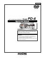
DVD LOCATION RECORDER
Model
PD-6
Operation Manual
<DANGER>
VISIBLE OR INVISIBLE LASER RADIATION WHEN OPEN.
AVOID DIRECT EXPOSURE TO BEAM.
<CAUTION>
• Use of controls or adjustments or performance of
procedures other than those specified herein may
result in hazardous radiation exposure.
• The use of optical instruments with this product will
increase eye hazard.
CAUTION
About DVD-RAM disks used with the PD-6
With the PD-6, only use DVD-RAM disks which is confirmed by Fostex.
Operation confirmed disk model: MAXELL DRMS-V28R (8-centimeter DVD-RAM
disk, double sided) *as of March 2003.
<Important notice>
Fostex does not guarantee the operation of the PD-6 when using a disk which is
not recommended by Fostex.
About disk formatting
Before starting recording, be sure to format the disk in either of the following
ways.a
•
For a brand-new disk:
Carry out the initial format (see page 24 in the operation manual).
•
For a used disk:
Carry out the physical format (see page 115 in the operation manual).
CAUTION
RISK OF ELECTRIC SHOCK
DO NOT OPEN
CAUTION:
TO PREVENT ELECTRIC SHOCK, MATCH WIDE BLADE OF
PLUG TO WIDE SLOT, FULLY INSERT.
ATTENTION:
CAUTION: TO REDUCE THE RISK OF ELECTRIC SHOCK,
DO NOT REMOVE COVER (OR BACK).
NO USER - SERVICEABLE PARTS INSIDE.
POUR EVITER LES CHOCS ELECTRIQUES, INTRODUIRE
LA LAME LA PLUS LARGE DE LA FICHE DANS LA BORNE
CORRESPONDANTE DE LA PRISE ET POUSSER JUSQU'
AU FOND.
REFER SERVICING TO QUALIFIED SERVICE PERSONNEL.
The lightning flash with arrowhead symbol, within an equilateral
triangle, is intended to alert the user to the presence of
uninsulated "dangerous voltage" within the product's enclosure
that may be of sufficient magnitude to constitute a risk of electric
shock to persons.
"WARNING"
The exclamation point within an equilateral triangle is intended
to alert the user to the presence of important operating and
maintenance (servicing) instructions in the literature
accompanying the appliance.
"TO REDUCE THE RISK OF FIRE OR ELECTRIC SHOCK,
DO NOT EXPOSE THIS APPLIANCE TO RAIN OR
MOISTURE."
SAFETY INSTRUCTIONS
10. Power Sources - The appliance should be connected to a power
supply only of the type described in the operating instructions or
1. Read Instructions - All the safety and operating instructions
should be read before the appliance is operated.
as marked on the appliance.
11. Grounding or Polarization - The precautions that should be taken
2. Retain Instructions - The safety and operating instructions
should be retained for future reference.
so that the grounding or polarization means of an appliance is
not defeated.
3. Heed Warnings - All warnings on the appliance and in the
operating instructions should be adhered to.
12. Power Cord Protection - Power supply cords should be routed
so that they are not likely to be walked on or pinched by items
4. Follow Instructions - All operating and use instructions should
be followed.
5. Water and Moisture - The appliance should not be used near
water - for example, near a bathtub, washbowl, kitchen sink,
laundry tub, in a wet basement, or near a swimming pool, and
the like.
6. Carts and Stands - The appliance should be used only with a
cart or stand that is recommended by the manufacturer.
placed upon or against them, paying particular attention to cords
at plugs, convenience receptacles, and the point where they
exit from the appliance.
13. Cleaning - The appliance should be cleaned only as
recommended by the manufacturer.
14. Nonuse Periods - The power cord of the appliance should be
unplugged from the outlet when left unused for a long period of
time.
15. Object and Liquid Entry - Care should be taken so that objects
do not fall and liquids are not spilled into the enclosure through
openings.
An appliance and cart combination should be moved with care.
Quick stops, excessive force, and uneven surfaces may cause
16. Damage Requiring Service - The appliance should be serviced
by qualified service personnel when:
7. Wall or Ceiling Mounting - The appliance should be mounted to
a wall or ceiling only as recommended by the manufacturer.
The power supply cord or the plug has been damaged; or
Objects have fallen, or liquid has been spilled into the appliance; or
The appliance has been exposed to rain; or
The appliance does not appear to operate normally or
exhibits a marked change in performance; or
E. The appliance has been dropped, or the enclosure damaged.
8. Ventilation - The appliance should be situated so that its location
or position dose not interfere with its proper ventilation.
17. Servicing - The user should not attempt to service the appliance
beyond that described in the operating instructions.
the appliance and cart combination to overturn.
For example, the appliance should not be situated on a bed,
sofa, rug, or similar surface that may block the ventilation
A.
B.
C.
D.
All other servicing should be referred to qualified service
personnel.
openings; or, placed in a built-in installation, such as a bookcase
or cabinet that may impede the flow of air through the ventilation
18. The appliance should be situated away from drops of water or
spray of water.
openings.
9. Heat - The appliance should be situated away from heat sources
19. Objects containing liquid such as vase must not be put on the
appliance.
such as radiators, heat registers, stoves, or other appliances
(including amplifiers) that produce heat.
20. The appliance is not completely isolated from the power supply
even if the power switch is at off position.
PD-6 DVD Location Recorder
Table of contents
Precautions .............................................................................................................................8
Precautions on safety ............................................................................................8
Precautions on installation ...................................................................................8
About this manual ............................................................................................................. .....9
Manual organization .............................................................................................9
Rules of manual description ..............................................................................11
Chapter 1: Introduction .......................................................................................................13
Introduction .........................................................................................................14
Main features / functions ...................................................................................14
What is in the box ................................................................................................16
PD-6 options and related Fostex products .......................................................16
Chapter 2: Before using the PD-6 ......................................................................................17
About power supply ............................................................................................18
About battery .........................................................................................................18
Charging the battery ..................................................................................18
Installing the battery ..................................................................................18
Removing the battery .................................................................................19
Saving the battery power ...........................................................................19
About AC adaptor .................................................................................................20
Connecting the AC adaptor .......................................................................20
Turning on the power ...........................................................................................21
About power supply voltage ................................................................................21
About Realtime clock ......................................................................................................22
About DVD-RAM disk ......................................................................................................22
Inserting / removing a disk .................................................................................23
About recording modes .......................................................................................26
Chapter 3: Names and functions .......................................................................................27
Left side panel (Inputs / outputs) .....................................................................28
Right side panel (Inputs / outputs) ..................................................................30
Front panel (part 1) .............................................................................................32
Front panel (part 2) .............................................................................................34
Front panel (part 3) .............................................................................................37
Top panel (part 1) ...............................................................................................38
Top panel (part 2) ...............................................................................................41
LCD display ...........................................................................................................43
Initial screen (Normal screen) .............................................................................43
Other screens .........................................................................................................44
4
PD-6 DVD Location Recorder
Chapter 4: Basic connections ............................................................................................47
Input connection .............................................................................................48
Analog audio input connection .....................................................................48
Digital audio input connection ......................................................................49
Time code input connection ..........................................................................49
Sync signal connection ....................................................................................49
Monitor signal input connection ...................................................................50
Output connection ..........................................................................................50
Analog audio output connection ...................................................................51
Digital audio output connection ....................................................................51
Time code output connection ........................................................................51
Word clock output connection ......................................................................51
Monitor output connection ............................................................................51
Connection examples .....................................................................................52
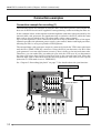
Connection example for recording (1) .........................................................52
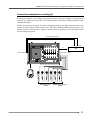
Connection example for recording (2) .........................................................53
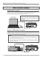
Other connection examples ..........................................................................54
Example of PC connection ...............................................................................54
Example of USB keyboard connection ..........................................................54
Power supply for external devices .................................................................55
Chapter 5: Recording / playback ........................................................................................57
Recording analog audio .................................................................................58
Selecting an input source ................................................................................59
Adjusting the input gain .................................................................................59
Filter setting ......................................................................................................60
Limiter setting ...................................................................................................60
Selecting the sampling frequency .................................................................61
Selecting recording tracks ..............................................................................62
Selecting a recording source ..........................................................................63
Adjusting the recording level .........................................................................63
Monitoring recording signals .........................................................................64
Making recording .............................................................................................65
Recording with the PRE REC mode active ...........................................66
Recording a slate tone/slate mic signal ..............................................67
About overloading .................................................................................67
File names of created audio files .........................................................68
Recording digital audio ..................................................................................69
Selecting digital input channels .....................................................................69
Selecting the sampling frequency .................................................................69
Selecting the system master clock .................................................................69
Recording time code .......................................................................................70
Selecting the TC frame rate .............................................................................70
Selecting the TC generate mode .....................................................................71
Setting the time code output ..........................................................................71
Jam function ....................................................................................................72
5
PD-6 DVD Location Recorder
Creating cue points .........................................................................................73
Creating a cue point automatically at the recording start point ...............73
Creating a cue point on-the-fly ......................................................................73
Viewing the cue point list ................................................................................74
Editing a cue point ...........................................................................................74
Creating a new cue point using the cue list screen ......................................75
Playback ...........................................................................................................76
Normal audio playback ...................................................................................76
Time code playback .........................................................................................77
Cueing playback ...............................................................................................77
Skip/locate functions .....................................................................................78
Skipping by file .................................................................................................78
Skipping by cue point ......................................................................................78
Locating to the beginning (ABS 0) of a file ....................................................78
Locating to the end (REC END) of a file .........................................................78
Locating to the previous locate point ............................................................78
Locating to the desired time ...........................................................................79
Locating to the desired cue point ..................................................................79
Chapter 6:TC Setup mode ..................................................................................................81
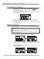
How to select the TC Setup menu .................................................................82
Editing the LTC start time ..............................................................................82
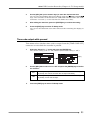
Time code output while paused ...................................................................83
User bit setting of playback time code .........................................................84
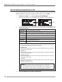
Editing the internal time code generator setting .......................................85
User bit setting of internal generator time code ........................................86
Jam mode setting ............................................................................................86
Chapter 7: Setup mode ........................................................................................................87
Setup menu details .........................................................................................88
How to select a Setup menu ...........................................................................89
How to make Setup menu setting .................................................................90
Adjusting the real-time clock (Adjust RTC) .................................................90
Setting the digital out format (Digital out) ...................................................91
Digital input channel setting (Digital in) ......................................................91
Skip mode setting (Skip mode) ......................................................................92
Diagnoses on/off setting (Diagnoses) ...........................................................92
Reference level setting (Reference level) ......................................................93
Peak hold time setting (Peak hold) ................................................................93
Slate tone recording time and mode setting (Tone rec mode) ..................94
Auto cue mode on/off setting (Auto cue) .....................................................95
Pause cancel time setting (Pause time) .........................................................95
Error tone output setting (Error tone) ..........................................................96
Battery warning setting (BATT warning) ......................................................97
Speaker mute on/off setting (Speaker mute) ..............................................97
Limiter parameter setting (Limiter parameter) ..........................................98
Default file name setting (Default file name) ...............................................99
6
PD-6 DVD Location Recorder
Default track name setting (Default track name) .....................................100
Next event number setting (Next event No.) .............................................100
USB keyboard type setting (Keyboard) ......................................................101
Pre-record time setting (Pre rec time) ........................................................101
Setup data saving (Save user setup) ...........................................................102
Setup data loading (Load user setup) .........................................................102
ROM version checking (Version) .................................................................103
Chapter 8: Utility mode ......................................................................................................105
Utility menu details ......................................................................................106
How to select a Utility menu ........................................................................107
Editing a file name [Edit file name] ............................................................108
Editing a file information editing [File info.] ............................................109
Checking file information ...........................................................................109
Checking a description information ..........................................................109
Editing a description information ..............................................................111
Adding a description information .............................................................111
Deleting a description information ...........................................................111
Deleting an unnecessary audio file [Delete file] ......................................112
Restoring a deleted audio file [Restore Del. file] ......................................113
Optimizing the current disk [Optimize disk] ...........................................114
Formatting the current disk [Format] .......................................................115
Editing the reel number (volume label) [Reel No.] ..................................118
Selecting the record protection “On” or “Off” [Rec protect] .................119
Selecting the resume function “On” or “Off” [Resume] ..........................120
Setting IEEE1394 connection [IEEE1394] .................................................121
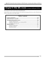
Chapter 9: EDL SEL mode ................................................................................................123
Creating a new ALE file .................................................................................124
Adding audio files to an ALE file .................................................................127
Viewing and editing audio file entries .......................................................129
Viewing audio file entries .............................................................................129
Adding an audio file entry to an existing ALE file .....................................130
Deleting an audio file entry ..........................................................................130
Editing an ALE file .........................................................................................131
Editing an ALE file name ...............................................................................131
Remaking an ALE file .....................................................................................132
Deleting an ALE file ........................................................................................133
Chapter 10: Exporting files using IEEE1394 ..................................................................135
Connection between the PD-6 and a PC ....................................................137
How to disconnect the PD-6 ........................................................................137
Example of copying data to an external hard disk ..................................138
Example of exporting data to a computer application ...........................138
Chapter 11: Specifications ...............................................................................................141
7
PD-6 DVD Location Recorder
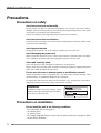
Precautions
Precautions on safety
Avoid excessive heat and humidity
Do not expose the PD-6 to extremes of humidity. Do not place the unit in direct
sunlight, close to heating units, or in areas subject to high temperatures. Also avoid
areas subject to extremely low temperatures.
The PD-6’s ambient operating temperature is between 0º and 45ºC.
Avoid excessive dust and vibration
Locations which are subject to excessive dust accumulation or vibration which could
cause mechanical damage.
Avoid physical shocks
Strong physical shocks can cause damage. Handle the unit with care.
Avoid damaging the power cord
Make certain that the PD-6’s power cord is not located in a position where it is likely
to be walked on or pinched by other equipment placed near the cord.
Clean with a soft dry cloth
Never use solvents such as benzine or thinner to clean the PD-6.
Wipe it clean with a soft dry cloth. If further cleaning is required, a lightly moistened
cloth with a mild detergent may be used.
Do not open the case or attempt repairs or modification yourself
The PD-6 contains no user-serviceable parts. For other than routine cleaning, refer
all maintenance to qualified FOSTEX service personnel.
To reduce the risk of electric shock, do not open the case. Opening the case and/or
tampering with the internal circuitry will void the warranty.
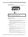
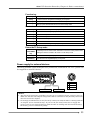
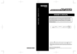
<Important!>
Equipment name, electrical ratings, serial
number and other information for the PD-6,
are written on bottom side.
MODEL PD-6
DVD LOCATION RECORDER
FOSTEX CO.
INPUT: 12VDC
SERIAL NO.
MADE IN JAPAN
Precautions on installation
Do not install the unit in the following conditions
- in a extremely hot or cold place
- in a moist place
- in a dusty place
- in a strong magnetic field or near a device which generates a magnetic field
- in the direct sunshine
8
PD-6 DVD Location Recorder
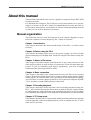
About this manual
This manual is intended to be used as a guide for using the Fostex PD-6 DVD
location recorder.
It is divided into Chapters. Each Chapter covers instructions for a specific
subject or feature of the PD-6 which you should know for using the unit, as
well as safety instructions, precautions, etc. Please retain this manual at hand
so that you can read it whenever necessary.
Manual organization
The following shows a brief description of each chapter though you may
know the contents of each chapter by the “Table of Contents”.
Chapter 1: Introduction
This chapter describes the brief introduction of the PD-6, as well as main
features.
Chapter 2: Before using the PD-6
This chapter describes some notes on the power supply, as well as details
about formatting a DVD-RAM disk. Read this chapter first before using the
PD-6.
Chapter 3: Names of Functions
This chapter describes names and functions of keys and controls on the
front and top panels, as well as those of connectors on the left and right side
panels. If you are familiar with digital equipment, you may roughly
understand the functions the PD-6 offers.
Chapter 4: Basic connection
This chapter describes basic connection between the PD-6 and external
devices. It includes details about how to connect analog audio signals, digital
audio signals, an external time code, and external synchronization signals,
as well as how to connect between the PD-6 and a personal computer by IEEE
1394, and how to make USB keyboard connection.
Chapter 5: Recording/playback
This chapter describes audio and time code recording/playback using the
PD-6. You can find description about how to make necessary switch setting
or adjustment for audio and time code recording/playback, as well as about
force jamming. Descriptions for the skip and locate functions are also included.
Chapter 6: TC Setup mode
This chapter describes the TC Setup mode which provides preferences/settings
related with time code recording/playback, such as settings for the TC start
time and TC user bits.
9
PD-6 DVD Location Recorder
Chapter 7: Setup mode
This chapter describes details about menus in the Setup mode. Using Setup
mode menus, you can set preferences, etc. of the PD-6. The following menus are
available in the Setup mode.
<Note>
The Setup mode menu may change when the PD-6 software is updated.
Real Time Clock menu
You can check or edit the internal real-time clock.
Digital Out menu
You can select the digital output signal format between AES/EBU and
SPDIF.
Digital In menu
You can select the input channel sources between digital and analog.
Skip mode menu
You can select the function of the [SKIP/CURSOR] key.
Diagnoses menu
You can select whether logging errors during recording to the diagnoses
file or not.
Reference level menu
You can select the PD-6 reference input level.
Peak hold time menu
You can set the peak hold time of the level meters.
Tone rec mode menu
You can set the recording duration and mode of the slate tone.
Auto cue menu
You can select whether automatically recording a cue point or not at
the record start position.
Pause time menu
You can set the pause cancel time.
Error tone menu
BATT warning menu
You can select on or off of the error tone.
You can set the threshold of the battery power voltage for generating
the error tone.
Speaker mute menu
You can select whether muting the monitor speaker or not except
during recording.
Limiter parameter menu
You can set the limiter parameters.
Default File name menu
You can select the name form of an audio file when it is created between
date information base and scene/take number information base.
Default track name menu
You can specify the default track name of audio files.
Next event menu
You can set the event number of audio files.
USB keyboard menu
You can select the USB keyboard type to be connected between US
and JAPAN.
Pre rec time menu
You can set the pre-record time of audio pooled in the buffer.
User setup save menu
You can save the setup data to the user box.
User setup load menu
You can load the setup data from the user box.
Version menu
You can check the PD-6 software version.
Chapter 8: Utility mode
This chapter describes the Utility mode, in which you can make settings related
with DVD-RAM disks to be used with the PD-6, as well as format a disk. The
following menus are available in the Utility mode.
<Note>
The Utility mode menu may change when the PD-6 software is updated.
10
PD-6 DVD Location Recorder
Edit File Name menu
You can edit audio file names.
File Info. menu
You can check the audio file information, as well as edit the description
information.
Delete File menu
You can delete an audio file.
Restore Del File menu
You can restore the deleted file.
Optimize Disk menu
You can optimize the current disk.
Format menu
You can format the current disk.
Reel No. menu
You can edit the reel No. (volume label).
Rec Protect menu
You can select record protection enabled or disabled.
Resume menu
You can select the resume function enabled or disabled.
IEEE1394 menu
You can select IEEE1394 connection enabled or disabled.
Chapter 9: EDL SEL mode
This chapter describes how to create an ALE file from a recorded audio file so as
to be used in the AVID system, as well as how to edit an ALE file information.
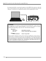
Chapter 10: Exporting files using IEEE1394
This chapter describes how to transfer audio files between the PD-6 and a
personal computer using IEEE1394.
Chapter 11: Main specifications
This chapter describes PD-6 specifications for mechanical and electronic
characters, etc.
Rules of manual description
This manual is described according to the following rules.
1.
The following abbreviations are sometimes used.
Time code
External time code
Internal time code generator
Sampling frequency
->
->
->
->
TC
EXT TC
INT TC GEN
Fs
2.
The names of keys and other connectors and controls of the PD-6 expressed
in this manual match the panel indication.
3.
The on-screen messages and switch position names are surrounded by “ “.
4.
The on-screen messages and items, as well as the indicators on the panel,
“light” or “flash”.
5.
“Notes” give a tip or advice for using the PD-6 properly. “Cautions” give
advice regarding a possible hazard to equipment or personnel.
11
PD-6 DVD Location Recorder
12
PD-6 DVD Location Recorder (Chapter 1: Introduction)
Chapter 1: Introduction
This chapter describes the introduction and main features/functions of the PD-6.
13
PD-6 DVD Location Recorder (Chapter 1: Introduction)
Introduction
The model PD-6 is a portable 6-track DVD location recorder using an 8centimeter DVD-RAM disk as a recording medium.
To get the best performance in the circumstance of location recording, the
PD-6 is equipped with a six-channel mixer in a light-weighted and small body,
and you can make reliable long-time recording with an internal battery
(equivalent to the NP-1 type). The PD-6 also offers video/word sync capability,
allowing the perfect synchronization to video/picture equipment such as a
video camera. In addition, it is equipped with a connector, conformed to
IEEE1394, for direct connection to a personal computer, allowing transferring
recorded audio file data to a personal computer for editing.
The versatile functions of the PD-6 make it the best location audio recorder
for broadcasts and post productions.
Main features/functions
14
•
Equipped with an ATAPI 8-centimeter DVD-RAM drive.
This drive is designed vibrationproof, and ensures high-speed access
and reliability, which only the optical disk system can afford.
•
The DVD-RAM disk format is conformed to “UDF Rev1.5”, which ensures
great compatibility with personal computers.
•
The recording file format is conformed to the BWF interleave 1 file
specification. When a file is imported to a DAW such as the Pro Tools
from the PD-6, it is separated to mono files.
•
Various recording track modes are available. You can select a desired t
rack mode from among 2, 4, 5 and 6, as well as 2+4 and 1+5 track
modes.
•
Supports 44.1 kHz, 48 kHz, 88.2 kHz and 96 kHz sampling frequencies
with 24 bit quantization. At 44.1 kHz or 48 kHz sampling frequency,
you can also select 16 bit quantization.
•
Supports video and word synchronization, allowing the PD-6
synchronized with external devices (such as video cameras). The PD-6
automatically recognizes a video or word signal.
•
“Pre Record” function, a useful feature for location recording, allows to
store maximum 10-second recent audio data into the buffer. You can
start recording from the current audio data in the buffer. The buffer
time can be set between 1 and 10 seconds.
•
A six-channel analog mixer is built in. You can make direct track
recording or mix recording. For example, you can record signals of
channels 1 through 4 to tracks 1 through 4 respectively, while record
stereo mix (rough mix) signals to tracks 5 and 6.
PD-6 DVD Location Recorder (Chapter 1: Introduction)
•
Each mixer channel provides a pan pot, a phantom power supply (P48/
T12), a frequency-sweepable filter and a limiter.
In addition, each of channels 2, 4 and 6 provides a phase switch.
•
A 128 x 64 dot-matrix backlit LCD display for showing various
information is used, which helped to design the PD-6 compact and
lower power consumption.
You can select the display mode by a single key operation.
The level meter section can be enlarged.
•
A connector conformed to IEEE1394 is provided for connecting directly
to a personal computer. It allows transferring audio file data recorded
by the PD-6 between the PD-6 and a personal computer.
•
A USB port is provided for connecting directly to a USB keyboard. You
can make setting and editing from a keyboard instead of the PD-6 panel
keys. (Note that you cannot make all setting and editing from a
keyboard.)
•
The Cue function allows to store markers (cue points) during recording.
Cue points are used for the locate or skip function. (To use cue points
for the skip function, you have to set the “Skip mode” menu in the
Setup mode to “CUE”.)
•
The circle take function allows to put “@” to desired recorded audio
files. Using this function, you can make an “OK take” list easily.
•
The reference input level can be selected between -18 dB and -20 dB.
(The selection is made in the Setup mode. The default setting is -20
dB.)
•
Built in accurate TC generator (in +/- 1 ppm accuracy) for recording
IEC time code. The time code can be started by jamming to an external
time code or from the desired time of the internal clock.
The jam function switches the reference from an external time code to
the internal time code generator.
•
The error tone can be generated for warning when disk writing error
occurs, clipping occurs at the input amplifier stage, the power voltage
is out of the allowable range, or the remaining space of the disk is few.
(You have to make setting of the “Error tone” menu in the Setup mode
appropriately.)
15
PD-6 DVD Location Recorder (Chapter 1: Introduction)
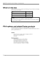
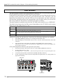
What is in the box
Make sure that the box contains the following. If any of them are missing,
please contact your dealer.
PD-6
1
Carrying belt
1
8-centimeter DVD-RAM disk (2.8 GB)
1
Operation manual (this manual)
1
<Note>
No internal battery nor AC adaptor is supplied with the PD-6.
Use an NP-1 type or equivalent for the internal battery. Use the Fostex optional
AD-15C for the AC adaptor.
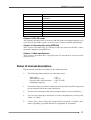
PD-6 options and related Fostex products
The following PD-6 options and related products are available.
Ask your local Fostex dealer or sale office for details about them such as
prices, specifications, etc.
Options
• External power supply unit (AC adaptor): AD-15C
• Soft case for the PD-6: ZP-6
• AATON
Related products
•
•
•
•
•
16
DVD digital master recorder: DV40
DAT portable digital recorder: PD-4
DAT digital master recorder: D-15
Personal powered monitor: 6301B/BX
Stereo headphones: T20RP/T-5/T40RP
PD-6 DVD Location Recorder (Chapter 2: Before using the PD-6)
Chapter 2: Before using the PD-6
This chapter describes notes for the power supply and DVD-RAM disks, which you should
know before using the PD-6.
<Table of contents>
About power supply .........................................................................................................18
About battery .........................................................................................................18
Charging the battery ...............................................................................................18
Installing the battery ...............................................................................................18
Removing the battery .............................................................................................19
Saving the battery power .......................................................................................19
About AC adaptor ..................................................................................................20
Connecting the AC adaptor ....................................................................................20
Turning on the power ...........................................................................................21
About power supply voltage ................................................................................21
About Realtime Clock ...................................................................................................................22
About DVD-RAM disk ...................................................................................................................22
Inserting/removing a disk ................................................................................................23
Initial format of a disk .......................................................................................................24
About recording modes ....................................................................................................26
17
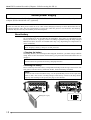
PD-6 DVD Location Recorder (Chapter 2: Before using the PD-6)
About power supply
The PD-6 is powered either by a battery which allows the unit to be used outside, or by the AC
adaptor (Fostex Model AD-15C, optional).
<Note>
Make sure that the PD-6 power switch is set to “OFF” when changing a battery or when disconnect the AC
adaptor from the unit. The unit continuously accesses data when the power is on, therefore, the memory
contents may be reset by the sudden power interruption.
About battery
No battery is supplied with the PD-6.
We recommend to use the IDX NP-L50, IDX NP23, Sony NP-1 or equivalent for the
battery of the PD-6. Typically 2-hour recording is possible using the fully charged
IDX NP-L50 (note that the recordable time may vary depending on temperature or
other condition).
<Note>
When charging a battery, charge to its full potential.
• Charging the battery
Normally, a battery is not charged when shipped, therefore, you must charge it before
using. Refer to the instruction of the battery you purchased for details about how to
charge it.
<Note>
The PD-6 does not provide the battery charging function.
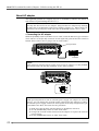
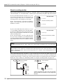
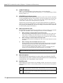
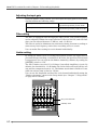
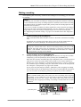
• Installing the battery
Insert a battery into the battery compartment firmly from the open end on the left
side panel, with the battery terminals inside, until the battery is locked.
<Note>
To run the unit on the installed battery, set the [POWER SEL] switch on the right side
panel to “INT”. Also set the “warning voltage of the battery” menu in the Setup mode
properly after turning on the power (see page 97 for details).
Battery (NP-1 type)
18
PD-6 DVD Location Recorder (Chapter 2: Before using the PD-6)
• Removing the battery
To remove the battery, set the [POWER] switch to “OFF” and slide the [EJECT] lever
beside the battery compartment to the arrow direction in the figure below.
<Caution>
NiCd batteries are recyclable. When disposing a used battery, follow your local
regulations regarding appropriate recycling procedures.
Do not leave the removed battery within children’s reach.
• Saving the battery power
The PD-6 offers the following measures for saving the battery power to extend the
battery life.
•
Pressing the [STOP] key stops the disk rotation to save the power
consumption. It is also possible to set the desired PAUSE release time
in the Setup mode (the default is three minutes).
•
When the internal monitor speaker is not used (i.e. when a headphones
plug is inserted to the [PHONES] jack), no power is supplied to the
amplifier for the speaker.
The following describes some tips for saving the battery power, as well as some notes
on using the battery.
•
The input impedance of devices connected to PD-6’s output connectors
should be greater than 10kΩ .
•
When convert a balanced output to unbalanced, do not connect the
unused pin to the ground pin and leave it open.
Though it lowers the output level 6dB, it does not influence to the
audio characteristics.
•
Set the monitor level as lower as possible (regardless of whether using
headphones or the internal monitor speaker).
•
When you do not operate the unit on battery power for a long period
of time, remove the battery or set the [POWER SEL] switch to “EXT”.
19
PD-6 DVD Location Recorder (Chapter 2: Before using the PD-6)
About AC adaptor
The optional genuine AC adaptor AD-15C is available. (Contact our dealer or
sale office for purchasing the AD-15C.)
<Notes>
Use only the AD-15C for an AC adaptor. Using another AC adaptor may damage
the PD-6 due to the mismatch of the power voltage, polarity, etc. When connect or
disconnect the AC adaptor, make sure that the [POWER] switch is set to “OFF”.
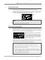
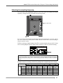
• Connecting the AC adaptor
While the [POWER] switch of the PD-6 is set to “OFF”, insert the XLR-4-32 type connector
of the AD-15C to the [DC IN] connector on the right side panel of the PD-6 until it is
locked. Then connect the AC plug to the AC main outlet.
[DC IN] connector
AD-15C
AC adaptor
<Note>
When using an external power supply such as the AC adaptor, set the [POWER
SEL] switch under the [DC IN] connector to the “EXT” position.
<Note>
While operating the PD-6 with an external power supply (AC adaptor or external
battery), you can change the AC main outlet connected to the adaptor or replace
the external power supply without TC interruption if the fully charged NP-1 type
is installed to the PD-6. See below for the procedure.
1) Make sure that the fully charged battery is installed to the PD-6.
2) Set the [POWER SEL] switch to “INT” from “EXT”.
3) Change the AC main outlet connected to the adaptor or replace the external
power supply.
4) Set the [POWER SEL] switch to “EXT” from “INT”.
20
PD-6 DVD Location Recorder (Chapter 2: Before using the PD-6)
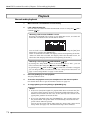
Turning on the power
When switch the [POWER] switch to “ON” after fitting the internal battery or
connecting the AC adaptor (AD-15C), the PD-6 works as follows.
If you turn on the power while no disk is inserted, the PD-6 releases the door
lock after recognizing that no disk is inserted, and shows “— Unlock door —
” is shown in the file name field on the LCD screen.
<Note>
The level, TC and Fs fields of the LCD screen show the settings according to the
switch positions when turning off the power last time. See “Display section” in
“Chapter 3: Names and Functions” for details.
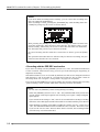
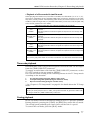
About power supply voltage
The output voltage of the power supply for the PD-6 must be within the
range between DC 12 to 18 volts. Never use the PD-6 at more than 18 volts or
less than 12 volts. You can check the internal battery voltage on the display
(indicated by the arrow in the screen example below).
The current battery voltage is shown in the dotted bar
meter.
Each dot corresponds to approximately 0.2 V. When the
battery voltage is less than 10.4 V, all dots are unlit. When
it is 14.0 V or more, all dots are lit. Note that the battery
life depends on the battery. The Also note that it fully lights
when the AC adaptor is used.
The PD-6 has the facility for sounding the warning tone from the internal
monitor speaker (or headphones) when the supplied voltage of the battery
or the external power supply voltage becomes improper.
<Notes>
• You can make the setting for generating the warning tone by the “Error tone”
menu in the Setup mode. See “Setup mode” on page 96 for details.
• If the power supply voltage exceeds 18 bolts, the PD-6 may be damaged. Never
supply more than 18 volts to the PD-6.
• If the battery is dead or the power supply section has a trouble by surge
current, etc., the protection circuit works and the power is shut off. In such a
case, set the [POWER] switch to “OFF”, replace the battery with a charged one,
then set the [POWER] switch to “ON” again.
If the PD-6 does not return to the normal condition after the operation above,
there may be some trouble in the circuit.
21
PD-6 DVD Location Recorder (Chapter 2: Before using the PD-6)
About Realtime Clock
The PD-6 offers realtime clock function.
The realtime clock data is used for a file name (date and time when the file is created)
when creating a new audio file on a disk, the time code start time when recording a time
code by the internal time code generator, and so on.
The realtime clock is adjusted according to the local time when shipped, therefore, set
the time to your local time before using the PD-6 (see “Chapter 7: Setup mode” on page
90 for details about realtime clock setting).
<Notes>
• When shipped, the file name mode is set to “DATE”, therefore, the realtime clock
data is automatically used as the name of an audio file name created when recording.
You can edit the file name later.
See “Chapter 7: Setup mode” on page 99 for details about file name editing and file
name mode setting.
file name
• Only when the TC GEN mode is set to “24H RUN”, the realtime clock data is used as
the TC start time (see “Recording/playback” on page 72 for details about the TC
GEN mode).
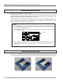
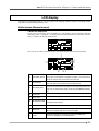
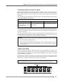
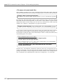
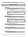
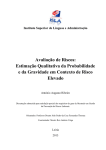
About DVD-RAM disk
The PD-6 uses MAXELL 8-centimeter DVD-RAM (double sided) disks shown below. You
can record data to both sides A and B. The arrows below show the direction for insertion.
<Side A>
22
<Side B>
PD-6 DVD Location Recorder (Chapter 2: Before using the PD-6)
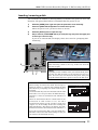
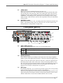
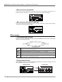
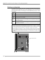
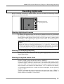
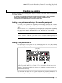
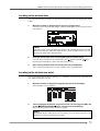
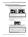
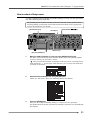
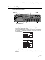
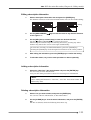
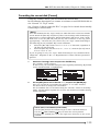
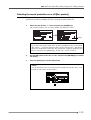
Inserting / removing a disk
You can insert or remove a disk regardless of whether the power is on or off,
however, the procedure below is assumed that the power is on.
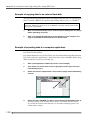
1)
Slide the [OPEN] lever right and open the protection cover manually.
2)
Press the [DISC UNLOCK] button to release the tray lock.
When the power is off, you do not have to do this.
3)
Slide the [EJECT] lever to open the tray.
4)
Set (or remove) a DVD-RAM disk to (or from) the tray and press the upper part
of the tray to close the tray.
If you set an unused disk, the display shows the screen for prompting disk
formatting.
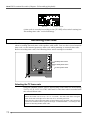
<Note>
When inserting a disk to the tray, make sure that the
direction is right.
2
<Note>
3
1
Depending on the condition when you turned off the power
last time, the disk lock may not be released on rare occasions . In such a case, turn off and on the power, then press
the [DISC UNLOCK] button again to release the disk lock.
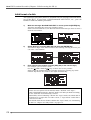
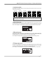
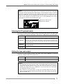
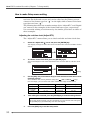
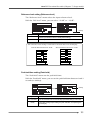
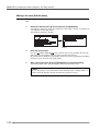
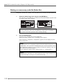
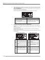
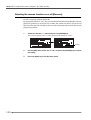
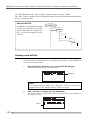
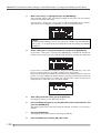
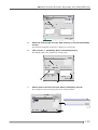
<Notes>
When setting an unused new disk, the message as
shown in <Figure 1> appears after reading the disk
information, prompting that disk formatting is
required.
An unused disk may not be formatted with the UDF
format Rev 1.5 or may not have the BWF directory,
therefore, it must be formatted with UDF Rev1.5
format.
<Figure-1>
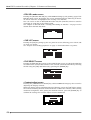
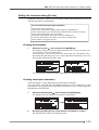
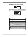
When an unformatted disk or a disk which is not
formatted in UDF format is set, the PD-6
automatically brings up the “Format” menu (see
<Figure 2>) in the Utility mode after reading the
disk information. This shows the disk is not UDFformatted and must be formatted with UDF Rev1.5.
If you do not format the disk, press the [EXIT] key.
The PD-6 releases the disk from locking so that you
can remove the disk from the tray.
<Figure-2>
23
PD-6 DVD Location Recorder (Chapter 2: Before using the PD-6)
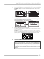
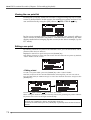
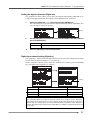
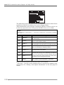
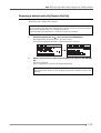
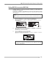
Initial format of a disk
The operation procedure below is assumed that an unused DVD-RAM disk is
set to the PD-6. If you have a disk formatted with FAT32, etc., you can
format it with the similar procedure.
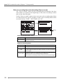
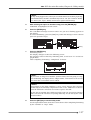
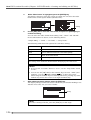
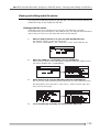
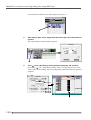
1)
While the message “Non-BWF-DVD FMT!” is shown, press the [ENTER] key.
The PD-6 automatically enters the “Format” menu.
When an unused disk is set, the Reel No field is blank and you have to enter a
desired reel number.
2)
Select “Reel No” using the [SEL] dial and press the [ENTER] key.
The leftmost digit of the Reel No field starts flashing, showing that now you
can enter a reel number.
3)
Enter a desired reel number using the [SEL] dial (or the numeric keys).
For example, you can enter “S001”.
Use the [
SKIP/CURSOR
] keys to move the cursor position.
When using the numeric keys for entering characters, pressing any other
numeric key moves the cursor to the right automatically.
<Note>
There are two options for the Format mode: “Normal” and “Tape”.
With a disk formatted in the “Normal” mode, each time you make recording,
a new audio file is automatically created.
Meanwhile, when formatting a disk in the “Tape” mode, the whole disk is
formatted as a single file. In other words, a “Tape mode” audio file is
created on a disk.
For details about how to format a disk in the “Tape” mode, see “Formatting
a disk” in “Chapter 8: Utility mode” on page 115.
24
PD-6 DVD Location Recorder (Chapter 2: Before using the PD-6)
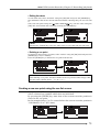
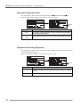
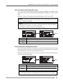
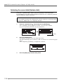
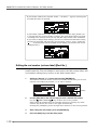
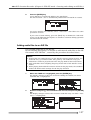
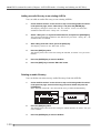
5)
Press the [ENTER] key twice to highlight “[EXECUTE]” and press the [ENTER]
key again.
The display changes to show the caution message, in which “Are you sure?”
flashes.
6)
Press the [ENTER] key.
Formatting starts.
The display now shows the approximate time required for formatting, as well
as the bar-graph meter which shows the progress.
When formatting finishes, “Fmt. Completed!” is shown.
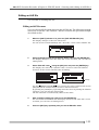
7)
Press the [EXIT] key to exit the Utility mode.
The display changes to shows the normal screen, on which “No Files!” is shown
in the file name field.
The disk is now formatted with UDF Rev1.5 and you can make recording or
playback.
The level, TC and BWF sections on the screen show the status according to the
[REC TR], [FS/24] and [FRAME] switch positions when formatting started.
8)
Format disk side B with the same procedure as above.
<Note>
On rare occasions, “Disk error!” appears on the display and the disk lock is
released after formatting is completed. In such a case, set “Physical format”
to “ON” in the “Format” menu and format the disk again (see “Format menu”
in “Chapter 8: Utility mode” on page 115 for details about the physical
format).
If “Disk error!” appears again after carrying out physical format, do not use
the disk.
25
PD-6 DVD Location Recorder (Chapter 2: Before using the PD-6)
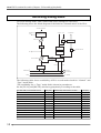
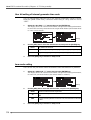
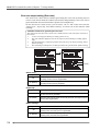
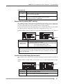
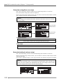
About recording modes
With a disk formatted in the UDF Rev1.5 “Normal” mode, you can make recording in the
“One file mode” or “Two file mode”, which can be selected by the [REC TR] select switch.
If you set the [REC TR] select switch to 2, 4, 5 or
6, recording is made by the “One file mode”, in
which a single audio file is created when
recording starts. See the figure on the right.
In the “One file mode”, each time recording is
made, a new audio file with the incremented
number is created.
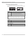
If you set the [REC TR] select switch to 2+4 or
1+5, recording is made by the “Two file mode”,
in which two audio files (two-track and four-track
files, or one-track and five-track files) are created
when recording starts.
In the “Two file mode”, two new audio file with
the successive numbers are simultaneously
created, in which the file with the smaller number
is the multitrack file and “M” is added to the file
name.
<One file mode>
2 TR
FILE
*******.wav (01)
Each file is individually created.
6 TR
FILE
*******.wav (02)
<Two file mode>
5 TR
FILE
*******M.wav (01)
Two files are simultaneously created.
1 TR
FILE
*******.wav (02)
<Note>
If a disk is formatted in the “Tape” mode, You cannot make recording in the “Two file mode”.
<Note>
The position of “M” added to a multitrack file name depends on the “File name mode” setting
in the “Default file name” menu of the Setup mode. See “Chapter 5: Recording/playback” on
page 68 for details.
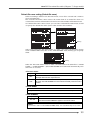
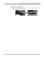
With a disk formatted in the “Normal” or “Tape” mode, files are stored in the “BWF” directory. An
8-centimeter DVD-RAM disk allows recording to both sides, so you can make recording in the
“Normal” mode on side A, while in the “Tape” mode on side B. For details about how to format a
disk in the “Tape” mode, see “Formatting a disk” in “Chapter 8: Utility mode” on page 115.
“Normal” mode disk
Resume. rsm
“Tape” mode disk
Resume. rsm
INF
O
INF
BW
F
******.wav (01)
******.wav (02)
******.wav (03)
******.wav (04)
******.wav (05)
******.wav (06)
******.wav (nn)
26
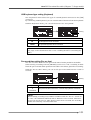
O
BW
F
Tape_mode1.wav (01)
If a disk is formatted in the “Tape” mode, the whole disk
side is formatted as a single file, so only a single audio
file exists.
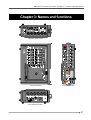
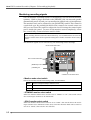
PD-6 DVD Location Recorder (Chapter 3: Names and functions)
Chapter 3: Names and functions
<Right side panel section>
<Top panel section>
<Front panel section>
<Left side panel section>
27
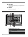
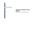
PD-6 DVD Location Recorder (Chapter 3: Names and functions)
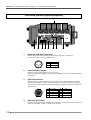
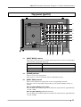
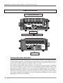
Left side panel (Inputs/outputs)
1
9
1.
8
7
6
5
4
2
3
[ANALOG LINE OUT] connectors
These connectors feed analog audio signals of tracks 1 through 6.
Connectors: XLR-3-32 type (balanced)
1
2
3
2.
1
2
3
GND
HOT
COLD
Internal monitor speaker
Outputs track audio signals, error tones, etc.
When a headphones plug is inserted to the [PHONES] jack, the monitor speaker
is inactive.
3.
[AUX I/O] connector
The input ports of the [AUX I/O] connector receive audio signals and route
them to the monitor circuit, while the output ports feed stereo buss signals.
You can select the output level from among three options using the [AUX OUT
ATT] switch.
8
1
9
10
5
4
2
7
6
4.
3
1
2
3
4
5
L OUT +
R OUT +
L OUT R OUT R IN +
6
7
8
9
10
R IN L IN +
L IN GND
GND
[AUX OUT ATT] switch
Switches the output level of signals sent from the output ports of the [AUX I/O]
connector among +4 dBu, -10 dBu and -60 dBu.
28
PD-6 DVD Location Recorder (Chapter 3: Names and functions)
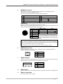
5.
[REMOTE] connector
This connector accepts parallel remote signals for controlling the PD-6
externally. Connector: MINI DIN 8-pin
You can control the following nine operations remotely.
1
PLAY
6
CUE point registration
2
STOP
7
PAUSE
3
RECORD
8
SKIP/CURSOR
4
REWIND
9
SKIP/CURSOR
5
F.FORWARD
<Operation>
When a terminal is grounded, the function is active.
Note that you can always control the PD-6 via this connector regardless of the
setting of the [PANEL LOCK] key on the panel.
8
6
7
5
1
2
3
4
5
6
7
8
4
2
3
1
PLAY
STOP
REC
GND
SHIFT
REW
VBATT *
FF
SHIT + STOP
SHIFT + REC
SHIFT + REW
SHIFT + FF
CUE
PAUSE
SKIP/CURSOR
SKIP/CURSOR
(*) V BATT (12 - 24 V). Max 500 mA.
This pin always supplies the voltage regardless of
whether the [POWER] switch is set to “ON” or “OFF”.
(delivers a voltage regardless of the [POWER] switch
setting.)
<Caution>
Pin 7 (DC 12V) supplies the PD-6 operation voltage. If it is short-circuited to
GND, or use it with a heavy load, the PD-6 internal battery life may be exhausted
faster or the PD-6 may generate heat abnormally.
Be careful not to use it with a heavy load or short-circuit it to GND.
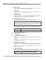
6.
[IEEE1394] connector
Exclusively used to connect to a PC, allowing you to transfer audio files
between the PD-6 and the PC.
1
2
3
4
1 2 3 4
7.
TPB TPB +
TPA TPA +
[USB] connector
Used to connect to a USB keyboard, allowing you to control the PD-6 from the
keyboard (see “Operation from a keyboard” on page 54).
1
8.
2
3
4
1
2
3
4
VBUS
DD+
GND
[EJECT] lever
Used to remove the internal battery (NP-1 type) from the battery compartment.
9.
Battery compartment
Stores the battery (NP-1 type).
29
PD-6 DVD Location Recorder (Chapter 3: Names and functions)
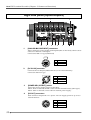
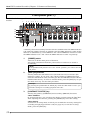
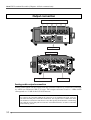
Right side panel (Inputs/outputs)
1
10
1.
9
2
8
7
6
5
4
3
[ANALOG MIC/LINE INPUT] connectors
These connector receive analog audio signals (mic or line level), which can be
sources of channels 1 through 6.
Connectors: XLR-3-31 type (balanced)
3
1
2
2.
1
2
3
GND
HOT
COLD
[DC IN 12V] connector
Connects the AC adaptor (Model AD-15C) or an external battery.
Connector: XLR-4-32 type
1
4
2
3
3.
1
2
3
4
GND
NC
NC
12V
[POWER SEL (INT/EXT)] switch
Selects the power supply source for the PD-6.
When “INT” is selected, the PD-6 runs with the internal battery (NP-1type).
When “EXT” is selected, it runs with an external power supply.
4.
[DC OUT] connectors
Each connector outputs DC 12 V power. You can supply power to up to two
external devices.
30
3
1
4
2
1
2
3
4
GND
NC
NC
12V
PD-6 DVD Location Recorder (Chapter 3: Names and functions)
5.
[TIME CODE OUT] connector
Outputs time code. Connector: XLR-3-32 type (balanced)
1
2
3
6.
GND
HOT
COLD
1
2
3
[TIME CODE IN] connector
Inputs external time code. Connector: XLR-3-31 type (balanced)
3
1
2
7.
GND
HOT
COLD
1
2
3
[WORD IN] terminate switch
Terminates the word input signal by setting the switch to “ON”.
8.
(Blank cap for installing the option)
This part is reserved for installing the optional AATON.
9.
[WORD/VIDEO IN]/[WORD OUT] connectors
The [WORD/VIDEO IN] connector receives word or video clock.
It automatically detects the clock type (word or video).
The [WORD OUT] connector feeds a word clock. Connectors: BNC type
10.
[DIGITAL I/O] connector
Receives and feeds AES/EBU or S/P DIF digital signals.
Connector: 25-pin D-sub connector
You can make AES/EBU or S/P DIF selection using the menu in the Setup mode.
Signal
13
25
1
14
Input 1/2
Input 3/4
Input 5/6
Input 7/8
Output 1/2
Output 3/4
Output 5/6
Output 7/8
Frame GND
Open
Hot
Cold
14
1
15
2
16
3
4
17
18
5
19
6
20
7
21
8
10, 12, 13, 22,
23, 24, 25
9, 11
Terminal
treatment
Open
GND
•
The pin assignment is compatible with the 25-pin D-sub connectors provide
on the Fostex 8350 and Yamaha equipment.
•
Recommended connection cable:
DBK-258, DB-25 (M), TO 4XLR (M), AND 4XLR (F), 5M (16.5FT.)
AES/EBU DIGITAL AUDIO TRANSFER CABLE
HOSA TECHNOLOGY,INC.
31
PD-6 DVD Location Recorder (Chapter 3: Names and functions)
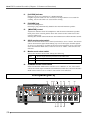
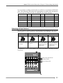
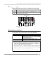
Front panel (part 1)
We divide the front panel into three parts and describe names and functions of controls for each
section.
1
2
12
11
3
4
5
6
7
8
16
15
14
13
10
9
* Some keys have the secondary function which is available when the SHIFT indicator
is lit, while the primary function is available when the SHIFT indicator is unlit. In this
manual, we sometimes say “when SHIFTed” and “when unSHIFTed” instead of “when
the SHIFT indicator is lit” and “when the SHIFT indicator is unlit” respectively.
1.
[POWER] switch
Turns on or off the main power of the PD-6.
The switch is fitted back from the panel surface in order not to switch it
accidentally.
<Note>
If the [PANEL LOCK] switch is set to the “LOCK” position, you cannot turn off
the power.
2.
[SHIFT] key/indicator
This key makes the shift mode active (the indicator is lit) or inactive (the
indicator is unlit). If you press a key which provides its SHIFTed function
while the shift mode is active, the PD-6 goes into the SHIFTed function which is
labeled under the key. To enter to another mode, press the [EXIT] key to quit
the mode and carry out the same procedure.
<Example>
By pressing the [CONTRAST/TC SETUP] key while the shift mode is active, you
can make settings for recording/playback time code.
3.
[CONTRAST/TC SETUP] key
This key has primary (unSHIFTed) and secondary (SHIFTed) functions.
• When unSHIFTed:
By pressing this key, you can adjust the display contrast using the [SEL] dial.
After adjusting the contrast, pressing the [ENTER] key stores the setting.
• When SHIFTed:
Activates the TC Setup mode, in which you can make the necessary settings for
recording and playing back time code (see page 81). To exit the TC Setup
mode, press the [EXIT] key.
32
PD-6 DVD Location Recorder (Chapter 3: Names and functions)
4.
[SETUP/UTILITY] key
This key has primary (unSHIFTed) and secondary (SHIFTed) functions.
•When unSHIFTed:
Enters the Setup mode in which you can make settings for the preferences (see
page 87). To exit from the Setup mode, press the [EXIT] key.
•When SHIFTed:
Enters the Utility mode in which you can make settings related with disks (see
page 105). To exit from the Utility mode, press the [EXIT] key.
5.
[FILE SEL/EDL SEL] key
This key has primary (unSHIFTed) and secondary (SHIFTed) functions.
•When unSHIFTed:
By pressing this key, you can selects an audio file from among the files recorded
on the current disk using the [SEL] dial (see page 77). After selecting the file,
pressing the [ENTER] key to confirm the setting.
•When SHIFTed:
Enters the EDL SEL mode. In this mode, you can create and edit an ALE file
which should be registered during recording (see page 123). To exit from the
EDL SEL mode, press the [EXIT] key.
6.
[TIME/DISP MODE] key
This key has primary (unSHIFTed) and secondary (SHIFTed) functions.
•When unSHIFTed:
Selects the time display mode from among ABS, LTC, TC IN and GEN.
•When SHIFTed:
Switches to the mode in which you can enlarge the level display section on the
screen (see page 44).
7.
[LIGHT] key
Used to turn on the LCD backlight.
By pressing the key instantly, the LCD backlight turns on for approximately
three seconds and then automatically turns off.
By pressing the key for more than three seconds, the backlight continues to
light up until pressing the key again.
<Note>
While operating the PD-6 with the internal battery, we recommend not to turn
on the backlight unless it is needed.
8.
[EXIT] key
Used to cancel edit operation or execution, as well as used to exit the setup or
Utility mode.
9.
[SEL] dial/[ENTER] key
The [SEL] dial is used to select a menu or enter characters in the Setup mode
and other editing modes.
The [ENTER] key confirms setting or executes the selected operation.
10.
LCD display
Displays audio input/output levels, settings, menus, etc. (see page 43).
33
PD-6 DVD Location Recorder (Chapter 3: Names and functions)
11.
[ACCESS] indicator
Indicates the access condition of a DVD-RAM disk.
It lights in green while it is not accessed, in orange while it is accessed for
reading, and in red while it is accessed for writing.
12.
[PHONES] jack
Connects headphones.
Inserting a plug automatically disables the internal monitor speaker.
13.
[MONITOR] control
Adjusts the monitor level of headphones and the internal monitor speaker.
Each press of the control pushes down the control to the same level as the
panel or pulls it up.
Turning the control counterclockwise until clicked turns off the monitor sound.
14.
SOLO monitor select switch
When the monitor mode select switch (see below) is set to “SOLO”, this switch
selects the monitor signal from among any one of the input channel signals
(1/M, 2/S, 3 through 6) or either of the stereo buss signals (L or R). Note that,
when the monitor mode select switch is not set to “SOLO”, this switch is not
effective.
15.
Monitor mode select switch
Selects the monitor mode from among the following.
16.
SOLO
Monitors singles selected by the SOLO monitor select switch.
ST
Monitors signals selected by the ST/MONO monitor select switch in stereo.
MONO
Monitors signals selected by the ST/MONO monitor select switch in mono.
ST/MONO monitor select switch
When the monitor mode select switch is set to “MONO” or “ST”, this switch
selects the tracks/input channels to be monitored. Note that, when the monitor
mode select switch is set to “SOLO”, this switch is not effective.
Front panel (part 2)
17
34
18 19
21
22
28 27 26
25
20
23
24
PD-6 DVD Location Recorder (Chapter 3: Names and functions)
17.
Alphanumeric keys
While the display shows the normal screen, pressing any of the numeric keys
enters the time data edit mode. After editing time data, you can locate to the
edited time position (see page 78). While the PD-6 is in any of the edit modes,
you can enter time data or name.
<Key example>
Using the “3” key, you can enter “d”, “e”, “f”, “D”, “E” and “F”, as well as “3”.
18.
[LOCATE] key
Locates to the desired position in the following manners.
19.
1)
While a cue point is selected, pressing the key locates to the selected cue
point (see page 79).
2)
While time data is edited, pressing the key locates to the edited time
position (see page 79).
3)
While the display shows the normal screen, pressing the key locates to
the previously located point (the default setting is “ABS 0”).
[CLEAR] key
Pressing this key functions as follows.
20.
1)
While entering characters:
Erases the next character on the right of the cursor position.
2)
While editing time data:
Clears time data and sets it to “00h 00m 00f 00sf”.
3)
While the “Peak hold” setting menu in the Setup mode is set to “∞”:
Resets the peak level indication on the level meters.
[
SKIP/CURSOR
] keys
These keys function as follows.
21.
1)
While the display shows the normal screen and the skip mode is set to
“File”:
Pressing the
(or
) key skips to “ABS 0” of the previous (or next)
audio file. You can skip to “ABS 0” of the desired audio file by pressing
the appropriate key as many times as required.
2)
While the display shows the normal screen and the skip mode is set to
“Cue”:
(or
) key skips to the previous (or next) cue point.
Pressing the
You can skip to the desired cue point by pressing the appropriate key as
many times as required.
3)
While editing time or a label in the edit mode:
(or
) key moves the cursor to right (or left).
Pressing the
[CUE] key
This key functions as follows depending on the recorder condition.
•
During recording:
By pressing this key during recording, the current position data is stored
as a cue point “on the fly”.
The data is entered into the next available cue point (see page 73).
•
In any condition except during recording:
Pressing this key brings up the cue point list, where you can check the
cue points which hold data. You can also locate to the desired cue point,
edit the cue point data and performs cue point entry (see page 73).
35
PD-6 DVD Location Recorder (Chapter 3: Names and functions)
22.
[CIRCLE TAKE] key
Adds “@” to the beginning of the name of the current audio file.
If the name of the current audio file already has “@” at the beginning, pressing
this key deletes “@”.
23.
[STANDBY] key/indicator (green)
During recording or playback, pressing this key pauses the recorder and lights
up the [STANDBY] indicator. Only this key can stop recording. You cannot stop
recording with any other key. You can set the pause release time using the
“Pause time” menu in the Setup mode (see page 95).
This key also can be used to clear an unsuccessful audio file you made last
time. By pressing the [STANDBY] key while holding down the [CLEAR] key and
then pressing the [ENTER] key, the last recording is canceled and the audio file
is cleared. (See page 66 for details.)
24.
[REC] key/indicator (red)
Pressing this key starts recording. Depending on the file format type (Normal
or Tape) and “PRE REC mode” setting (on or off), it works as follows.
1)
When recording to a disk formatted in the Normal mode:
Pressing this key automatically creates a new file and starts audio and
time code recording. The offset between the time code and ABS time
values after a second from the beginning of recording is also recorded.
2)
When recording to a disk formatted in the Tape mode:
Pressing this key starts recording onto the current file from the current
position.
3)
When recording with the PRE REC mode set to “ON”:
Pressing this key starts recording from the audio data stored in the buffer.
The offset between the time code and ABS time values after a second
from the beginning of recording is also recorded.
You can select the buffered time among 1 and 10 seconds using the
menu in the Setup mode (the default setting is 10 seconds).
<Note>
The recorded time code depends on the [TC GEN] select switch setting.
25.
Slate microphone
This internal slate microphone is active while you slide the [SLATE]
switch knob to the “MIC” position. The microphone level is automatically
controlled by AGC (Automatic Gain Control).
26.
[SLATE] switch
While sliding the switch knob to the [TONE] position, the slate tone is output.
While sliding the knob to the [SLATE] position, the internal slate microphone
is active.
36
TONE
While sliding the switch knob to the [TONE] position, the slate tone (at 1 kHz, reference
level) is fed to all tracks and stereo busses. During recording, you can record the slate tone.
MIC
The slate microphone signal is fed to all tracks and stereo busses.
By sliding the switch knob to the [MIC] position during recording, you can record the slate
microphone signal.
PD-6 DVD Location Recorder (Chapter 3: Names and functions)
27.
[JAM] switch
Used to execute the jamming function (see page 72).
When this switch is set to “ON” and the PD-6 is receiving external time code,
the internal time code generator takes over (jams) time code. Note that the
jamming function is only available when the [TC GEN] mode switch is set to
“FREE RUN”. Depending on the “JAM mode” menu setting in the TC Setup
mode, the PD-6 jams the time code user bits regardless of the [TC GEN] mode
switch setting.
28.
[PRE REC] switch
When this switch is set to “ON”, recording starts from audio data stored in the
buffer. The buffered time can be set using the “Pre rec time” menu in the
Setup mode (see “Setup mode” on page 101).
Front panel (part 2)
29
30
31
32
34
29.
33
[DISC FEED] switches
Each switch selects a recording source of corresponding track.
PRE
30.
Channel pre-fader signal is selected.
L BUS
R BUS
Stereo buss (L or R) signal is selected. The “L” signal can be assigned to the odd tracks,
while the “R” signal can be assigned to the even tracks.
POST
Channel post-fader signal is selected.
[PEAK] indicators
Each indicator lights up according to the input level of the input amplifier.
Lights in green: The input level is between -1 dB and -5 dB of the clipping level.
Lights in red: The input level is between 0 dB and -1 dB of the clipping level.
By setting “Input Clip” in the “Error tone” menu of the Setup mode to “On”,
the error tone is output from the monitor speaker (or headphones) whenever
the corresponding input channel receives a loud signal which makes the
indicator lit in red (see “Setup mode” on page 96).
31.
[PFL] keys
By pressing a [PFL] key, you can hear the pre-fader signal of the corresponding
channel from the internal monitor speaker or headphones.
When any of the [PFL] keys is pressed, the pre-fader signal takes priority to the
signal selected by the monitor selection switchs (SOLO monitor select switch,
Monitor mode select switch and ST/MONO monitor select switch).
37
PD-6 DVD Location Recorder (Chapter 3: Names and functions)
32.
[LEVEL] controls
Each control adjusts the analog input level of the corresponding channel (1 to
6). You can control the signal level sent to the stereo buss. When the [DISC
FEED] switch is set to “POST”, the [LEVEL] controlled signal is sent to the
corresponding track.
33.
[PAN] switches
Each switch sets pan for sending the channel signal to the stereo buss.
34.
[STEREO BUS LEVEL] control
Adjusts the stereo buss master level.
Top panel (part 1)
1
2
3
4
5
12
11
10
1.
9
8
7
6
[TC GEN] switch
Selects the generator mode for time code recording.
EXT (Ext Run)
38
Records an incoming external time code value as the start time.
FREE (Free Run)
Runs the internal generator by the free run mode, and records the current internal
generator time as the start time.
REC (Rec Run)
When recording to a new file, the generator records time code from the value
which continues to the last time code value of the previous audio file.
24H (24H Run)
Time code starts from the internal RTC (real-time clock) data.
PD-6 DVD Location Recorder (Chapter 3: Names and functions)
<Note>
See “Recording/playback” on page 70 for details about time code recording/
playback.
2.
[FRAME] switch
Selects the time code frame rate for recording, playback and generation by the
internal TC generator.
3.
23.976
American motion picture -0.1%
24
American motion picture
25
European film/PAL-SECAM video EBU
29.97DF
NTSC color with real time adjust
29.97
NTSC color
30DF
NTSC video/film
30
NTSC video/film
[CLOCK] switch
Selects the system master clock.
4.
INT
The internal clock is the master. “INT” is lit on the display.
EXT
The external word or video clock is the master. “EXT” is lit on the display.
The PD-6 automatically detects the clock type (word or video). When the PD-6 locks to a
word clock, “WORD” is lit. When it locks to a video clock, “VIDEO” is lit. When it does not
lock to the clock, “WORD” or “VIDEO” flashes and it runs with the internal clock reference.
DIGITAL
The external clock available in the external digital signal is the master. “DIGI” is lit on the
display. When the PD-6 locks to a clock, “DIGITAL” is also lit on the display. When it does
not lock to the clock, “DIGITAL” flashes and it runs with the internal clock reference.
[FS/24] switch
Selects the Fs (sampling frequency) and Bit (quantization bit) for recording.
Depending on the setting, the available recording track modes change as follows.
REC TR
5.
2
4
5
6
2+4
1+5
44.1/16
Yes
Yes
Yes
Yes
Yes
Yes
48/16
Yes
Yes
Yes
Yes
Yes
Yes
FS/24 44.1/24
SW 48/24
Yes
Yes
Yes
Yes
Yes
Yes
Yes
Yes
Yes
Yes
Yes
Yes
88.2/24
Yes
No
No
No
No
No
96/24
Yes
No
No
No
No
No
[REC TR] select switch
Selects the recording track mode from among the following.
2TR
You can record to a stereo-track file.
4TR
You can record to a four-track file.
5TR
You can record to a five-track file.
6TR
You can record to a six-track file.
2+4TR
You can record to a two-track file and a four-track file simultaneously.
1+5TR
You can record to a mono-track file and a five-track file simultaneously.
39
PD-6 DVD Location Recorder (Chapter 3: Names and functions)
<Note>
See “Chapter 2: Before using the PD-6” on page 26 for details about the recording
track modes.
<Note>
When a “Normal” mode audio file is played back, the level meters show the
levels of tracks selected by the [REC TR] select switch.
6.
[AUDIO FILE] select switch
Selects the file format (BWF or OPT) of a recording audio file. While the file is
played back, the switch setting takes priority.
<Note>
This software version does not support the “OPT” position. Always use the unit
with the [AUDIO FILE] select switch set to “BWF”.
7.
[TC OUT] switch
Selects the time code source (REPRO or GEN) fed from the [TIME CODE OUT]
connector.
<Note>
See “Chapter 6: TC Setup mode” for details about output time code setting.
8.
[PULL UP/DOWN] switch
Selects pull-up (+0.1 %) or pull-down (-0.1 %) of the sampling clock. The current
TC frame rate also changes according to the switch position.
9.
[OPEN] lever
Opens the tray protection cover.
To close the cover, press down the cover.
10.
[EJECT] lever
Opens the disk tray.
When a disk is set on the tray, release the disk lock by pressing the [DISC
UNLOCK] button before sliding the [EJECT] lever.
Normally, when no disk is set on the tray or the power is off, you can open the
tray by only sliding the [EJECT] lever.
<Note>
On rare occasions, the disk lock may not be released. In such a case, turn off
and on the power, then use the [DISC UNLOCK] button to release the disk lock.
11.
[DISC UNLOCK] button
Releases the disk lock. This button is effective only when a disk is set on the
tray.
To remove a disk, press this button then slide the [EJECT] lever to open the
disk tray.
12.
Disk tray
Sets a DVD-RAM disk.
To open the disk tray, use the [DISC UNLOCK] button and [EJECT] lever as
described above. To close the disk tray, press down the tray.
40
PD-6 DVD Location Recorder (Chapter 3: Names and functions)
Top panel (part 2)
13
14
15
16
17
18
23
13.
22
21
20
19
[INPUT MODE] switches
Each switch selects the type of analog audio input source for the corresponding
channel from among the following.
14.
L (Line)
Line-level input
D (Dynamic Mic)
Dynamic microphone
P (Phantom Power P-48)
48 V phantom powered microphone
T (Phantom Power T-12)
12 V phantom powered microphone
[PHASE] switches
Used to reverse the input phase.
Only even (2, 4 and 6) channels offer the [PHASE] switches.
15.
[INPUT GAIN] controls
Each control adjusts the input gain of the corresponding channel.
The gain control range differs depending on the [INPUT MODE] setting, as
follows.
When the [INPUT MODE] is set to “LINE”:
You can adjust the nominal input level within the range between approximately
-30 and +4dBu.
When the [INPUT MODE] is set to “D”, “P” or “T”:
You can adjust the nominal input level within the range between approximately
-60 and -26dBu.
41
PD-6 DVD Location Recorder (Chapter 3: Names and functions)
16.
[HPF] controls
Each control controls the high-pass filter cutoff frequency of the corresponding
channel within the range between 50 Hz and 300 Hz.
17.
[HPF] switch
Each switch selects the high-pass filter response of the corresponding channel
from among “OFF”, “-6 dB/oct.” and “-12 dB/oct.”.
18.
[LIMITER] switch
Each switch selects the limiter for the corresponding channel active or inactive.
The limiter parameters can be set using the “Limiter parameter” menu in the
Setup mode (see “Chapter 7: Setup mode” on page 98).
19.
[STOP] key/indicator (green)
Stops the recorder, as well as stops the disk rotation. This key is also used to
exit a menu operation (of the Setup mode, Utility mode, etc).
<Note>
While operating the PD-6 with the battery, we recommend using the [STOP] key
to stop playback rather than using the [PAUSE] key. Because using the [STOP]
key stops the disk rotation, which saves battery power.
By pressing the [REW] or [F FWD] key while holding down the [STOP] key, the
following operation is possible.
20.
[STOP] + [REW]
Locates to the beginning (ABS 0) of the current file.
[STOP] + [F FWD]
Locates to the recording end (REC END) of the current file.
[PLAY] key/indicator (green)
Starts playback.
21.
[F FWD] key/indicator (green)
Pressing this key while stopped fast-forwards the recorder at maximum 30 x
speed.
Pressing this key during playback fast-forwards with sound (cues forwards) at
2 x speed.
Pressing this key while holding down the [STOP] key locates the recording end
(REC END) of the current file.
22.
[REW] key/indicator (green)
Pressing this key while stopped rewinds the recorder at maximum 30 x speed.
Pressing this key during playback rewinds with sound (cues backwards) at 2 x
speed.
Pressing this key while holding down the [STOP] key locates the beginning
(ABS 0) of the current file.
23.
[PANEL LOCK] switch
Switches the panel lock function active (LOCKED) or inactive (OFF).
When set it to the “LOCKED” position, the following keys/switch are inactive.
[STOP] key, [PLAY] key, [F FWD] key, [REW] key, [CIRCLE TAKE] key,
[
SKIP/CURSOR ] key, [FILE SEL] key, [LOCATE] key, [POWER] switch
42
PD-6 DVD Location Recorder (Chapter 3: Names and functions)
LCD display
The PD-6 is equipped with a 128 x 64 dot LCD display, which shows recording levels,
recorder status, setting menus, etc.
Initial screen (Normal screen)
• When no disk is set
If you turn on the PD-6 when no disk is set, the display shows something like the
following. After “—No Disk—” is briefly shown and the door lock is released, “-Unlock
door-” is shown in the file name field.
This screen is called “Normal screen” and includes the following information.
2
3
4
5
1
6
9
8
7
1
Level meter section
Shows the recording/playback level meters. The number of meters depends
on the track mode selected by the [REC TR] switch. The screen above
shows the example when the 2-track mode is selected.
2
File name field
Shows the audio file name (up to 13 characters) or the frame rate of external
time code while LTC IN is shown in the time display field.
3
Time display field
Show the time value of the current file position in “ABS” or “LTC”. It also
can show an external time code value or internal generator time code
value. You can select the time display mode using the [TIME/DISP MODE]
key.
4
Remain field
Shows the remaining recordable time of the disk.
5
File No. field
Shows audio file No.
6
File information field
Shows Fs, bit and recording track mode of the file. It follows the [REC TR]
and [FS/24] switch settings.
7
Clock field
Shows the current reference clock (INT, EXT or DIGITAL).
8
Battery field
Shows the internal battery voltage.
When the AC adapter (AD-15C) is used, it fully lights.
9
TC field
Shows the frame rate of recording time code and TC GEN mode.
It follows the [FRAME] and [TC GEN] switches.
43
PD-6 DVD Location Recorder (Chapter 3: Names and functions)
• When you set an unused disk
If you set an unused disk after turning on the PD-6, the display prompts you to
format the disk, as below. See page 24 for details about disk formatting.
• When you set a disk with recorded data
If you set a disk with recorded data after turning on the PD-6, the file name and No.
are shown in the appropriate fields.
Other screens
• Time display mode selection
Each press of the [TIME/DISP MODE] key (when unSHIFTed) switches the time display
mode in the following order.
LTC
LTC IN
GEN
ABS
LTC
Shows LTC recorded on the disk. You can set the start time of LTC recording using the
appropriate menu in the TC Setup mode.
LTC IN
Shows incoming external LTC. If no LTC is received, “————” is shown.
ABS
Shows the absolute time, which is set to “00H00M00S00SF” at the beginning of the file.
GEN
Shows time code generated by the internal TC generator.
The value depends on [TC GEN] switch setting.
• Display mode selection
While SHIFTed, each press of the [TIME/DISP MODE] key switches the display between
the “Normal screen” and “Level screen”.
<Normal screen>
44
<Level screen>
PD-6 DVD Location Recorder (Chapter 3: Names and functions)
• Level meter section
Depending on the [REC TR] select switch setting, the level meter section on the screen
looks like the following.
2TR mode
4TR mode
5TR mode
6TR mode
2+4TR mode
1+5TR mode
<Note>
With a “Tape” mode file, the level meter section looks the same regardless of the
[REC TR] select switch setting.
• Setup mode screen
Pressing the [SETUP/UTILITY] key (while unSHIFTed) brings up the primary page of
the Setup mode screen. Using Setup mode menus, you can set preferences, etc. of the
PD-6. See “Chapter 7: Setup mode” on page 87 for details about the Setup mode.
• Utility mode screen
Pressing the [SETUP/UTILITY] key while SHIFTed brings up the primary page of the
Utility mode screen. Using Utility mode menus, you can make settings related with
DVD-RAM disks to be used with the PD-6, as well as format a disk.
See “Chapter 8: Utility mode” on page 105 for details about the Utility mode.
• TC Setup mode screen
Pressing the [CONTRAST/TC SETUP] key while SHIFTed brings up the primary page
of the TC Setup mode screen. Using the TC Setup mode menus you can make
preferences/settings related with time code recording/playback.
See “Chapter 6: TC Setup mode” on page 81 for details about the TC Setup mode.
45
PD-6 DVD Location Recorder (Chapter 3: Names and functions)
• EDL SEL mode screen
Pressing the [FILE SEL/EDL SEL] key while SHIFTed brings up the primary page of the
EDL SEL mode screen. By default, the screen something like the following is shown,
on which <New file> is highlighted for creating a new ALE file.
You can create or edit an EDL (Edit Decision List) file (ALE file) which is used for
exporting an audio file to the AVID system.
See “Chapter 9: EDL SEL mode <creating and editing an ALE file>” on page 123 for
details about the EDL SEL mode.
• CUE LIST screen
Pressing the [CUE] key brings up the cue point list screen, allowing you to check, edit
or create cue points.
See “Chapter 5: Recording/playback” on page 73 for details about cue points.
• FILE SELECT screen
Pressing the [FILE SEL] key brings up the audio file list screen, on which all audio files
recorded on the current disk is shown. You can load a desired audio file by selecting
the file using the [SEL] dial followed by pressing the [ENTER] key.
• Contrast adjust screen
Pressing the [CONTRAST/TC SETUP] key while unSHIFTed brings up the screen for
adjusting the display contrast.
While the display shows something like the following, rotate the [SEL] dial to adjust
the contrast. Rotating the dial counterclockwise weakens the contrast, while rotating
clockwise strengthens. After getting the desired contrast, press the [ENTER] key to
confirm the setting. The contrast adjust screen is dismissed.
46
PD-6 DVD Location Recorder (Chapter 4: Basic connections)
Chapter 4: Basic connections
This chapter describes the basic connection between the PD-6 and external devices.
<Table of contents>
Input connection ............................................................................................................48
Analog audio input connection ...................................................................................48
Digital audio input connection ....................................................................................49
Time code input connection .........................................................................................49
Sync signal connection ..................................................................................................49
Monitor signal input connection .................................................................................49
Output connection ........................................................................................................50
Analog audio output connection .................................................................................51
Digital audio output connection ..................................................................................51
Time code output connection ......................................................................................51
Word clock output connection ....................................................................................51
Monitor output connection ..........................................................................................51
Connection examples ...................................................................................................52
Connection example for recording (1) .......................................................................52
Connection example for recording (2) .......................................................................53
Other connection examples .........................................................................................54
Example of PC connection .............................................................................................54
Example of USB keyboard connection ........................................................................54
Power supply for external devices ...............................................................................55
47
PD-6 DVD Location Recorder (Chapter 4: Basic connections)
Input connection
Analog audio signals (mic/line)
Sync signal
External time code
Digital audio devices
Analog audio devices
Analog audio input connection
The PD-6 provides six analog mic/line input channels (channels 1 through 6) with sixchannel mixing capability, which allows location mixing and recording without the need
of an external mixing console. Six balanced XLR-3-31 type connectors, which accept a
wide range of audio signal level from mic to line, are used.
To record an analog audio signal, connect an analog source to any of the six [ANALOG
IN] connectors (XLR-3-31 type), and set the corresponding [INPUT MODE] switch to the
appropriate position (LINE, D, P or T) according to the input source. See “Chapter 5:
Recording/playback” on page 57 for details about the [INPUT MODE] switch setting.
The PD-6’s six-channel mixer provides the phantom power supply which allows the PD6 to accept condenser microphones, as well as dynamic microphones. It also provides
HPFs (High Pass Filters) and limiters.
48
PD-6 DVD Location Recorder (Chapter 4: Basic connections)
Digital audio input connection
The PD-6 accepts digital signals conformed to IEC 60958 (AES/EBU) or IEC 60958 (S/P
DIF) format (the format of the digital source is automatically detected). The digital
connection is made via the D-sub 25-pin DIGITAL I/O connector.
To record a digital audio source, connect a digital source to the [DIGITAL I/O] connector,
and set the digital input channels appropriately using the “Digital in” menu in the Setup
mode. The digital input channels can be set in 2-channel pairs (1-2, 3-4 and 5-6).
When the PD-6 receives a digital source from the selected channel, PLL (Phased-locked
loop) activates and locks to the input sync signal.
<Note>
When the sampling frequency of the input signal does not match the [FS/24] switch
setting, the switch setting indication shown on the screen flashes for warning.
Time code input connection
The [TIME CODE IN] connector (balanced, XLR-3-3-1) accepts SMPTE/EBU time code.
To record external time code, set the [TC GEN] mode switch to “EXT RUN”.
When the PD-6 receives valid external time code from the [TIME CODE IN] connector,
the “EXT TC” indicator is lit on the screen. When time code satisfies the following
conditions, it is “valid”.
1)
Runs in normal direction and value is continuous.
2)
Sync word matches the frame rate.
3)
Time code is not dropped out.
• For details about how to jam to external time code, see “Chapter 5: Recording/playback”
described later.
Sync signal connection
The PD-6 provides the [WORD/VIDEO IN] connector (BNC type) which is used to lock the
PD-6 to an external word or video reference. The connector accepts a word or video
clock from an external device, which easily makes the PD-6 locked to the external device.
The PD-6 also provides the [WORD OUT] connector which feeds a word clock to an
external device.
Monitor signal input connection
The PD-6 provides the [AUX IN] connector which receives an external monitor signal. A
Hirose 10-pin connector is used for the [AUX IN] connector.
The signal received by the [AUX IN] connector is sent to the PD-6 monitor section, and
can be monitored via headphones (or internal monitor speaker) in the similar manner
to stereo buss signals.
49
PD-6 DVD Location Recorder (Chapter 4: Basic connections)
Output connection
Analog audio devices
Analog devices
External digital devices
Digital devices
External device
Analog audio output connection
Analog audio signals can be output from the [ANALOG LINE OUT] connectors (1 through
6), which are balanced, XLR-3-32 type. The output reference level is +4 dBu which
corresponds to -12 dB of the LCD level meters.
<Note>
To connect the [ANALOG LINE OUT] connector to an unbalanced input, only use
the GND and hot pins. With this connection, the output level is 6 dB lower than
the balanced connection but there is no audio quality deterioration. Connecting
the cold pin to the GND pin increases the crosstalk and noise, as well as consumes
more battery power.
50
PD-6 DVD Location Recorder (Chapter 4: Basic connections)
Digital audio output connection
The digital audio signals can be output from the [DIGITAL OUT] connector (D-sub 25pin type) in the IEC 60958 (AES/EBU) or IEC 60958 (S/P DIF) format.
You can select the digital output signal format (AES/EBU or S/P DIF) using the “Digital
out” menu in the Setup mode (. See page 91 for details about the “Digital out” menu.
Time code output connection
You can output SMPTE/EBU time code from the [TIME CODE OUT] connector (balanced,
XLR-3-32 type).
According to the [TC OUT] switch setting, time code recorded on a disk (REPRO TC) or
generated by the internal time code generator (INT GEN TC) can be output.
Word clock output connection
Using the [WORD OUT] connector (BNC type), you can feed a word clock to a digital
device which needs to get a word clock for synchronization.
Monitor output connection
The stereo buss L/R signals can be output from the [AUX OUT] connectors. So, you can
monitor the stereo buss signals from an external monitor system, as well as from the
internal monitor speaker and headphones.
51
PD-6 DVD Location Recorder (Chapter 4: Basic connections)
Connection examples
Connection example for recording (1)
The following shows the example of using the PD-6 with microphones, which makes the
best use of the PD-6 and can be applied to news gathering, audio recording for film, etc.
In the example below, audio signals from microphones and time code generated by the
external time code generator are simultaneously recorded to the PD-6, while the same
time code is also recorded to the VTR along with a video camera signal.
Up to six microphones can be connected to the PD-6 input channels. Each of the input
channels provides the phantom power supply, gain control, limiter and high-pass filter,
allowing the PD-6 to accept any kinds of microphones.
The external time code generator output is connected to both the VTR’s time code input
and the PD-6 [TIME CODE IN] connector. Using the PD-6 jam function, the PD-6 time
code generator can run with extreme accuracy after it locks to the external time code.
Therefore, you can make PD-6 recording in sync with the VTR even if you disconnect
the time code input after the PD-6 generator locks to the external time code. When the
external time code is disconnected, the internal generator runs with its own crystal
(when the TC GEN mode is set to “FREE RUN”).
See “Chapter 5: Recording/playback” on page 72 for details about the jam function.
External Time code generator
TC
VTR
ANALOG MIC/LINE IN
Camera
52
PD-6 DVD Location Recorder (Chapter 4: Basic connections)
Connection example for recording (2)
In the next example, four main microphones (mono) and two ambience microphones
(stereo) are connected to the PD-6 six-channel mixer, allowing recording without using
an external mixer.
Unlike the previous example, the time code generated by the PD-6 internal time code
generator is the master which is fed to the VTR. The [ANALOG LINE OUT] connector can
always feeds the mixed source signals, which can be recorded to the VTR audio tracks
for the backup purpose.
For the backup purpose
LINE IN
TC
ANALOG LINE OUT
VTR
ANALOG MIC/LINE IN
Main microphones
(mono)
Ambience microphones
(stereo)
53
PD-6 DVD Location Recorder (Chapter 4: Basic connections)
Other connection examples
Example of PC connection
The PD-6 provides the IEEE1394 connector. By connecting a personal computer to this
connector, you can control the PD-6 drive from the personal computer.
See page 135 for details about audio file export/import.
<Note>
To use the PD-6 with a personal computer, make
setting of the “IEEE 1394” menu in the Utility mode
to “CONNECT”. See “Chapter 8: Utility mode” on page
121 for details.
Personal Computer
supporting IEEE1394
PD-6
IEEE1394
Example of USB keyboard connection
The PD-6 provides the [USB] connector only for connecting a USB keyboard. By connecting
a USB keyboard to this connector, you can enter file and label names, as well as carry
out some of menu operations, from the keyboard.
<Notes>
• To control the PD-6 from the USB keyboard, make setting of the [Keyboard” menu in
the Setup mode appropriately (“US” or “JAPAN”) according to the keyboard connected.
See “Chapter 7: Setup mode” for details.
• With some keyboard, indicators may not light until pressing a key after connection.
• We cannot guarantee to work correctly if you use a keyboard with built-in USB hub,
USB mouse or PS2 mouse.
PD-6
F1
ESC
~
`
!
1
TAB
@
2
Q
SHIFT
F3
E
S
Z
R
D
X
Alt
F5
F4
%
5
$
4
#
3
W
A
Caps Lock
Ctrl
F2
Help
^
6
T
F
C
&
7
Y
G
V
)
0
I
J
N
F8
(
9
*
8
U
H
B
F7
F6
O
K
M
F10 F11 F12
_
-
+
=
{
[
P
L
<
,
F9
J
>
.
K
?
/
Back Space
}
]
|
/
ENTER
SHIFT
Alt
USB keyboard
54
Print
Screen
SysReq
Scroll
Lock
Insert
Home
Page
Up
Num
Lock
Delete
End
Page
Down
7
Home
8
4
5
1
End
2
Pause
Break
/
*
-
9
Pg Up
+
6
3
Pg Dn
Enter
Ctrl
0
Ins
.
Del
USB
PD-6 DVD Location Recorder (Chapter 4: Basic connections)
Function key
F1 key
Brings up the “Edit file name” menu in the Utility mode.
F2 key
Acts the same as the [CIRCLE TAKE] key on the panel.
F3 key
Brings up the “Default file name” menu in the Setup mode.
F4 key
Brings up the “Default track name” menu in the Setup mode.
Shortcuts
ALT + F keys
Acts the same as the [FILE SEL] key on the panel.
ALT + C keys
Acts the same as the [CUE] key on the panel.
ALT + S keys
Enters the Setup mode.
ALT + U keys
Enters the Utility mode.
ALT + T keys
Enters the TC Setup mode.
ALT + E keys
Enters the EDL SEL mode.
CTRL + L keys
Acts the same as the [LOCATE] key on the panel.
Enters the TC Setup mode.
UP/DOWN
LEFT/RIGHT
key
ESC key
ENTER key
These keys can be used to enter characters or move the cursor position when
editing the name for a label or file name or in the Setup mode.
Acts the same as the [EXIT] key on the panel.
Acts the same as the [ENTER] key on the panel.
Power supply for external devices
The PD-6 provides a pair of the [DC OUT] connectors, from which “DC 12 V” power can
be supplied to external devices.
1
2
3
4
External device
3
1
4
2
GND
NC
NC
DC12V
External device
<Notes>
• The [DC OUT] connectors can deliver, in total, up to 0.5 ampere electric current at DC 12V.
Make sure that the total ampere rating of the devices connected to the [DC OUT] connectors
does not exceed 0.5 ampere.
• We strongly recommend to use the [DC OUT] connectors while the PD-6 is running with the
AC adaptor (or an external battery). If you use the [DC OUT] connectors to supply the
power to one or two external devices while the PD-6 is running with the internal battery,
the battery power is exhausted quickly.
55
PD-6 DVD Location Recorder (Chapter 4: Basic connections)
56
PD-6 DVD Location Recorder (Chapter 5: Recording/playback)
Chapter 5: Recording/playback
This chapter describes basic audio and time code recording/playback, as well as cue point creation
and skip/locate function.
<Table of contents>
Recording analog audio ........................................................................................................................58
Selecting an input source ............................................................................................................59
Adjusting the input gain .............................................................................................................59
Filter setting ..................................................................................................................................60
Limiter setting ...............................................................................................................................60
Selecting the sampling frequency ..............................................................................................61
Selecting recording tracks ...........................................................................................................62
Selecting a recording source .......................................................................................................63
Adjusting the recording level .....................................................................................................63
Monitoring recording signals ...............................................................................................64
Making recording .........................................................................................................................65
Recording with the PRE REC mode active ......................................................................66
Recording a slate tone/slate mic signal .........................................................................67
About overloading ...........................................................................................................67
File names of created audio files ....................................................................................68
Recording digital audio .........................................................................................................................69
Selecting digital input channels ................................................................................................69
Selecting the sampling frequency .............................................................................................69
Selecting the system master clock .............................................................................................69
Recording time code ..............................................................................................................................70
Selecting the TC frame rate ........................................................................................................70
Selecting the TC generate mode ................................................................................................71
Setting the time code output ......................................................................................................71
Jam function ...........................................................................................................................................72
Creating cue points ................................................................................................................................73
Creating a cue point automatically at the recording start point ...........................................73
Creating a cue point on-the-fly ..................................................................................................73
Viewing the cue point list ............................................................................................................74
Editing a cue point .......................................................................................................................74
Creating a new cue point using the cue list screen ..................................................................75
Playback ..................................................................................................................................................76
Normal audio playback ...............................................................................................................76
Time code playback .....................................................................................................................77
Cueing playback ...........................................................................................................................77
Skip/locate functions .............................................................................................................................78
Skipping by file .............................................................................................................................78
Skipping by cue point ..................................................................................................................78
Locating to the beginning (ABS 0) of a file ................................................................................78
Locating to the end (REC END) of a file ......................................................................................78
Locating to the previous locate point ........................................................................................78
Locating to the desired time .......................................................................................................79
Locating to the desired cue point ...............................................................................................79
57
PD-6 DVD Location Recorder (Chapter 5: Recording/playback)
Recording analog audio
To record analog audio, some control and switch settings are necessary.
The following shows the block diagram of the built-in 6-channel mixer of the PD-6.
ANALOG MIC/LINE IN
P48V
T12V
MIC AMP
(PHASE: ch 2/4/6)
TO REC
INPUT GAIN
PLAY
HP / MON SP
SW
D/A
HPF
A/D
SW
PFL
ANALOG LINE OUT
LIMITER
PRE FADER
LEVEL CONTROL
DISK FEED SW
POST FADER
Trk 1/3/5
Trk 2/4/6
PAN
L
STEREO BUSS
R
AUX OUT
HP / MON SP
HP / MON SP
AUX IN
The following table shows availability of PD-6 record modes both for “Normal” and
“Tape” mode disks.
*The availability for a “Tape” mode disk is shown in parentheses.
Set the [FS/24] and [REC TR] switches appropriately according to the table.
58
44.1kHz/16bit, 44.1kHz/24bit 2 track
Yes (Yes)
48kHz/16bit, 48kHz/24bit 1+5 track
Yes (No)
48kHz/16bit, 48kHz/24bit 2 track
88.2kHz/24bit 2 track
Yes (Yes)
Yes (Yes)
88.2kHz/24bit 4 track
No (No)
96kHz/24bit 4 track
No (No)
96kHz/24bit 2 track
Yes (Yes)
88.2kHz/24bit 5 track
No (No)
44.1kHz/16bit, 44.1kHz/24bit 4 track
Yes (Yes)
96kHz/24bit 5 track
No (No)
48kHz/16bit, 48kHz/24bit 4 track
Yes (Yes)
88.2kHz/24bit 6 track
No (No)
44.1kHz/16bit, 44.1kHz/24bit 5 track
Yes (Yes)
96kHz/24bit 6 track
No (No)
48kHz/16bit, 48kHz/24bit 5 track
Yes (Yes)
88.2kHz/24bit 2+4 track
No (No)
44.1kHz/16bit, 44.1kHz/24bit 6 track
Yes (Yes)
96kHz/24bit 2+4 track
No (No)
48kHz/16bit, 48kHz/24bit 6 track
Yes (Yes)
88.2kHz/24bit 1+5 track
No (No)
44.1kHz/16bit, 44.1kHz/24bit 2+4 track
Yes (No)
96kHz/24bit 1+5 track
No (No)
48kHz/16bit, 48kHz/24bit 2+4 track
Yes (No)
44.1kHz/16bit, 44.1kHz/24bit 1+5 track
Yes (No)
PD-6 DVD Location Recorder (Chapter 5: Recording/playback)
You can make recording on both sides A and B of an 8-centimeter DVD-RAM
disk. The following table shows the approximate recording time (in minute)
for each side according the [FS/24] and [REC TR] switch settings.
44.1kHz/16bit-2TR
118
44.1kHz/24bit-2TR
78
88.2kHz/24bit-2TR
39
48kHz/16bit-2TR
108
48kHz/24bit-2TR
72
96kHz/24bit-2TR
36
44.1kHz/16bit-4TR
59
44.1kHz/24bit-4TR
39
48kHz/16bit-4TR
54
48kHz/24bit-4TR
36
44.1kHz/16bit-5TR
47
44.1kHz/24bit-5TR
31
48kHz/16bit-5TR
43
48kHz/24bit-5TR
28
44.1kHz/16bit-6TR
39
44.1kHz/24bit-6TR
26
48kHz/16bit-6TR
36
48kHz/24bit-6TR
24
Selecting an input source
Set the [INPUT MODE] switch appropriately according to the source
(microphone or line) connected to the [ANALOG MIC/LINE IN] connector.
Mic input
Line input
“L” position
“D” position
“P” position
“T” position
For a line level analog
audio signal
For a dynamic
microphone
For a condenser
microphone which
requires the DC 48 V
phantom power.
Fo r a c o n d e n s e r
microphone swhich
requires the DC 12 V
phantom power.
On channels 2, 4 and 6, the [PHASE] switches are provided, allowing reversing
the phase.
[INPUT SEL] select switches
[PHASE] switches
[INPUT GAIN] controls
59
PD-6 DVD Location Recorder (Chapter 5: Recording/playback)
Adjusting the input gain
Using the [INPUT GAIN] control, you can adjust the input gain for each mixer
channel within the following range.
When the [INPUT MODE] switch is set to “D”, “P” or “T”: You can adjust the norminal input level within the
range between approximately -60 and -26 dBu.
When the [INPUT MODE] switch is set to “L:
You can adjust the norminal input level within the
range between approximately -30dB and +4 dBu.
Filter setting
The PD-6 is equipped with the high-pass filter circuit. The cutoff frequency
can be adjusted within the range between 50 Hz and 300 Hz, and the filter
slope can be selected between -6 dB/oct. and -12 dB/oct.
The filter is useful to eliminate the wind noise during location recording or
unnecessary low frequency noise when recording voice or sound.
You can make filter setting for each channel individually.
Limiter setting
By using the limiter when recording microphone sound, the signal level is
prevented from exceeding a certain level. In result, the signal level fluctuation
is suppressed. You can activate the limiter channel by channel, by setting the
[LIMITER] switch to “ON”.
The PD-6 limiter uses the VCA (Voltage Controlled Amplifier) circuit. By
default, the threshold is -12 dB under the 24-bit full-scale level (all bits are
on) and the compressed ratio is 1:3. The limiter attack time is fixed to 20 ms,
while the release time is fixed to 150 ms.
You can set the threshold and level for each channel individually using the
“Limiter parameter” menu in the Setup mode (see “Chapter 7: Setup mode”
on page 98 for details).
[HPF] control and switch
[LIMITER] switch
60
PD-6 DVD Location Recorder (Chapter 5: Recording/playback)
Selecting the sampling frequency
You can select the sampling frequency (Fs) only when recording an analog
signal by using the [FS/24] switch on the top panel.
[FS] select switch
You can select the Fs (and quantization bit) from among 44.1/16 bit, 48/16
bit, 44.1/24 bit, 48/24 bit, 88.2/24 bit and 96/24 bit. The current setting is
shown on the screen.
While receiving a digital signal, the PD-6 automatically detects the Fs from
the receiving digital signal, which takes priority to [FS/24] switch setting.
<Note>
During recording, you cannot change the Fs. If you change the [FS/24] switch
setting during recording, the switch setting becomes effective when recording
stops.
Available formats for recording (related to the [FS/24] switch and [REC TR] switch settings)
REC TR
2
FS SW
4
5
6
2+4
1+5
Yes
Yes
44.1/16
Yes
Yes
Yes
Yes
Yes
48/16
Yes
Yes
Yes
Yes
Yes
Yes
44.1/24
Yes
Yes
Yes
Yes
Yes
48/24
Yes
Yes
Yes
Yes
Yes
Yes
88.2/24
Yes
No
No
No
No
No
96/24
Yes
No
No
No
No
No
61
PD-6 DVD Location Recorder (Chapter 5: Recording/playback)
Selecting recording tracks
According to the situation, select the recording track mode from among the
following using the [REC TR] select switch. Depending on the selected mode,
the level meter section on the display is shown differently (except a “Tape”
mode disk).
2TR
You can record to a stereo-track file.
4TR
You can record to a four-track file.
5TR
You can record to a five-track file.
6TR
You can record to a six-track file.
2+4TR
You can record to a two-track file and a four-track file simultaneously.
For example, you can record sources directly to the four-track file and a rough stereo
mix to the two-track file.
1+5TR
You can record to a mono-track file and a five-track file simultaneously.
For example, you can record sources directly to the five-track file and a rough mono
mix to the a mono-track file.
<Notes>
• When playing back each individual file recorded in the “2+4TR” or “1+5TR”
mode, the audio fed from the [ANALOG LINE OUT] connectors differs depending
on the [REC TR] switch position. See “Playback” on page 78 for details.
• When making recording to a “Tape” mode disk, the [REC TR] switch setting is
not needed. The recording track mode is determined by the [REC TR] switch
setting when the disk has been formatted. See “Format menu” on page 115 for
details.
[REC TR] select switch
62
PD-6 DVD Location Recorder (Chapter 5: Recording/playback)
Selecting a recording source
Using the [DISC FEED] switches, select a recording source for each track.
PRE
L, R BUS
POST
Channel pre-fader signal is selected.
Stereo buss (L or R) signal is selected. The “L” signal can be assigned to the odd
tracks, while the “R” signal can be assigned to the even tracks.
Channel post-fader signal is selected.
[DISC FEED] switch
[STEREO BUS LEVEL]
control
[LEVEL] control
Adjusting the recording level
According to the recording source selected by the [DISC FEED] switch, use
the appropriate control to adjust the record level for each channel.
When set to “PRE”:
Use the [INPUT GAIN] control.
Use the [LEVEL] control to adjust the level sent from each
channel to the stereo buss, and use the [STEREO BUS LEVEL]
When set to “L BUS” (or “R BUS”):
control the total recording level.
Also select the pan position from among L, C and R.
When set to “POST”:
Use the [LEVEL] control.
<Notes>
• Adjust the recording level appropriately so that the level meter does not exceed
“0 dB”. To get the maximum signal-to-noise performance, set the level
appropriately so that the meter indication does not exceed “0 dB” but goes up
near to the “0 dB” at the loudest part of the signal.
The reference level is set to “-20 dB” by default, which means, +4 dBu signal
shows -20 dB from the 24-bit full-scale level (0 dB) on the level meter. You can
change the reference level to “-18 dB” using the “Ref. level” menu in the Setup
mode. See “Chapter 7: Setup mode” on page 93 for details.
• You can set to generate the error tone if the input amplifier clips using the
“Error tone” menu in the Setup mode (see page 96).
63
PD-6 DVD Location Recorder (Chapter 5: Recording/playback)
Monitoring recording signals
You can monitor recording signals via headphones (or the internal monitor
speaker). While a plug is inserted to the [PHONES] jack, the internal speaker
automatically turns off, and you can monitor the signals only via headphones.
The monitor level can be adjusted by the [MONITOR] control. This control is
a push-lock type. By pushing the head of the control, the control comes out
and you can rotate the control to adjust the level. Pressing the control again
puts it inside the panel. To turn off the monitor sound completely, rotate
the control fully counterclockwise until it clicks.
<Note>
While running the PD-6 with the internal battery, we recommend not to raise the
monitor volume more than required. Raising the volume consumes more battery
power.
The monitor signal can be selected by the following switch settings.
Monitor mode select switch
SOLO monitor select switch
[MONITOR] control
[PHONES] jack
ST/MONO monitor select switch
• Monitor mode select switch
Selects the monitor mode from among SOLO, ST and MONO.
SOLO
Monitors a single track/input channel in mono.
ST
Monitors a stereo mix of tracks/input channels.
MONO
Monitors a mono-mix of tracks/input channels.
• ST/MONO monitor select switch
When the monitor mode select switch is set to “MONO” or “ST”, this switch selects
the tracks/input channels to be monitored.
• SOLO monitor select switch
When the monitor mode select switch is set to “SOLO”, this switch selects the track/
input channel to be monitored. Note that, when the monitor mode select switch is
not set to “SOLO”, this switch is not effective.
64
PD-6 DVD Location Recorder (Chapter 5: Recording/playback)
Making recording
After making the necessary switch/level settings for recording, you can start
recording.
<Note>
By default, you can make recording of analog input signals of all mixer channels
if each channel receives only an analog signal. If a channel receives both an analog
and digital signals, the digital signal takes priority and the analog signal of this
channel is not recorded.
If you want to make recording of analog signals for some channels and digital
signals for the other channels simultaneously, use the “Digital in” menu in the
Setup mode to select the analog or digital inputs for each two-channel pairs.
See “Digital input channel setting” on page 91 for details about the “Digital in”
menu.
1.
To start recording, slide the [REC] key.
With a Normal mode disk, the PD-6 creates a “New File” and starts recording
to it.
By default, the real-time clock time data is given as the file name when an
audio file is created. (Example: “B19h 00m 30s 06jan 2003.wav”)
<Note>
Using the “Default file name” menu in the Setup mode, you can set the
default file name given when an audio file is created to “desired scene
name + take number” instead of the real-time clock time data. See “Chapter
7: Setup mode” on page 99 for details.
2.
To stop recording, press the [STANDBY] key.
During recording, only the [STANDBY] key is effective. To stop the recorder
completely, press the [STOP] key after pressing the [STANDBY] key.
Note that the recorder automatically stops completely after a certain period of
time since it enters the pause mode. This period is set to three minutes by
default, but can be changed to a desired period between 0.1 and 9.9 minutes
in 0.1 minute steps or infinity using the “Pause time” menu in the Setup mode.
See “Chapter 7: Setup mode” on page xx for details.
If you press the [LOCATE] (or [STOP] + [REW]) key after stopping recording,
the recorder locates to the beginning of the newly created audio file. Therefore,
you can check the recording by pressing the [PLAY] key in this condition.
<Note>
With a Normal mode disk, every time you start recording after stopping
recording, a new audio file is created and recording is made from the
beginning of the new file. With a Tape mode disk, every time you start
recording after stopping recording, recording is made from the current
position.
[REC] key
[PRE REC] switch
[SLATE] switch
[STANDBY] ley
65
PD-6 DVD Location Recorder (Chapter 5: Recording/playback)
<Note>
If you have made recording unsuccessfully, you can cancel the recording and
clear the audio file immediately.
After recording is made, pressing the [STANDBY] key while holding down the
[CLEAR] key brings up the screen as shown below.
Then pressing the [ENTER] key cancels the recording you made last time and
clears the audio file. After the PD-6 clears the file, the display shows "Completed!" briefly, followed by the screen of the audio file which was loaded before the audio file you have just cleared was made.
To cancel clearing the file while the screen above is shown, press the [EXIT]
key.
The operation described above is effective only for the last recording, and you
cannot restore the file once it is cleared.
• Recording with the PRE REC mode active
If you start recording with the [PRE REC] switch set to “ON”, the buffered audio data
is also recorded. This function may prevent you from missing the beginning of
important recording.
The buffered time is set to 10 seconds by default, but this can be changed to desired
time between 1 and 10 seconds in 1 second steps using the “Pre rec time” menu in
the Setup mode. See “Chapter 7: Setup mode” on page 101 for details.
If you press the [STANDBY] key to stop recording, the recorder will stop after executing
“post recording” which records audio data currently stored in the buffer.
<Notes>
• Do not alter the [PRE REC] switch setting during recording.
• When the [PRE REC] switch is set to “ON”, the [ANALOG LINE OUT] connectors
output analog audio input signals with no delay, but output a delayed digital
input signal.
• If you switch the Fs setting to “ON”, wait for 10 seconds before starting recording.
Otherwise, the audio signal stored in the buffer is recorded with the pitch altered.
• When making recording at 88.2kHz or 96kHz Fs with the “Pre rec” switch set to
“ON”, the maiximum buffered time is kimited to five seconds. Therefore, even
if you set the “Pre rec time” menu to more than 5 seconds, the recording buffer
can hold only 5-second audio data.
66
PD-6 DVD Location Recorder (Chapter 5: Recording/playback)
• Recording a slate tone/slate mic signal
While sliding and holding the [SLATE] switch to “TONE” or “MIC”, the slate tone (at 1
kHz, reference level) or the slate microphone signal is fed to all tracks and stereo
busses, allowing you to record the slate tone or the slate microphone signal during
recording.
You can adjust the recording level of the slate tone in the following manners depending
on the [DISC FEED] switch setting.
The setting of the [DISC FEED] switch
PRE position
L, R BUS position
POST position
Regardless of the [LEVEL] and The [STEREO BUS LEVEL] control The [LEVEL] control can be used to
[STEREO BUS LEVEL] control can be used to adjust the slate tone adjust the slate tone recording level.
settings, the slate tone is recorded recording level.
at the reference level.
If you set the “Tone rec mode” menu in the Setup mode appropriately, the slate tone
is automatically recorded at the beginning of an audio file when recording is made to
a “Normal” mode disk. (Note that this function is not available when recording to a
“Tape” mode disk.)
You can set the duration of the slate tone automatically recorded between 1 and 10
seconds (default: 10 seconds), as well as select between two types; continuous tone
or 4 pop tones. For details, see “Tone rec mode” on page 94.
<Notes>
• The slate tone is used for analog level calibration, therefore, it is not recorded
when selecting the digital input.
• While sliding and holding the [SLATE] switch to the “TONE” position, the slate
tone is output from the [ANALOG LINE OUT] connectors, allowing to calibrate
external devices.
• About overloading
While receiving an analog audio signal, if the input amplifier is clipped, the
corresponding PEAK indicator is lit in red. The responsibility of the detecting circuit
is approximately 10 milliseconds, and the indicator lights for more than 1.5 seconds
against momentary clipping.
By setting the “Input clip” item to “On” using the “Error tone” menu in the Setup
mode, the error tone is generated from the internal speaker or headphones for
warning. See “Chapter 7: Setup mode” on page 96 for details.
<Note>
If the [MONITOR] control is set to “OFF”, you cannot hear the error tone.
[PEAK] indicator
67
PD-6 DVD Location Recorder (Chapter 5: Recording/playback)
• File names of created audio files
When making recording in any of the single-file modes (2TR, 4TR, 5TR or 6TR), the
real-time clock time data when starting recording is given as the file name by default.
Example: “B15h 11m 25s 07jan 2003.wav”
The leftmost “B” stands for “BWF”. The file extension (“.wav”) is automatically appended.
By setting the “File name mode” item to “Take” instead of “Date” using the “Default
file name” menu in the Setup mode, “Scene name + Take number” is given as the
default file name. In this setting, you can also set a desired scene name and take
number. See “Chapter 7: Setup mode” on page 99 for details.
Example: “Action-001.wav” (when “SCENE NAME” and “TAKE NUMBER” are set to
“Action” and “-001” respectively.) The file extension (“.wav”) is automatically appended.
If you repeat creating new files in the above setting, the similar file name as above,
except that the take number is automatically incremented, is given to each file.
If you make recording in either of two-file mode (2+4TR or 1+5TR), the names of two
created files given are as below.
When “Default file name” is set to “Date”:
File 001: “M15h 11m 25s 07jan 2003.wav” (begins by “M”)
File 002: “B15h 11m 25s 07jan 2003.wav”
When “Default file name” is set to “Take” (when “SCENE NAME” and “TAKE NUMBER”
are set to “Action” and “-001” respectively.):
File 001: “ActionM-001.wav” (“M” is appended after the scene name)
File 002: “Action-001.wav”
In both cases, “M” stands for “multitrack”. File 001 (with “M”) corresponds to the 4track or 5-track file. Also note that, for the two files created in two-file mode, the
younger file number is always assigned to the multitrack file. In the example above,
001 is assigned to the multitrack file, while 002 is assigned to 1 or 2 track file.
68
PD-6 DVD Location Recorder (Chapter 5: Recording/playback)
Recording digital audio
Before executing recording of digital audio, you have to make the following settings
besides record track selection.
[FS/24] select switch
[CLOCK] select switch
Selecting digital input channels
By default, the digital inputs are selected as channel sources for all channels
(1 through 6). Therefore, when each pair channels (1-2, 3-4 and 5-6) receive
digital input signal which is locked, they accept it and allow to make digital
recording. If the digital input signal is not locked, the analog input is
automatically selected.
<Note>
Using the “Digital in” menu in the Setup mode, you can select the input sources between
digital and analog for each input channel pair (1-2, 3-4 and 5-6). Therefore, it is
possible to accept and record digital and analog sources simultaneously. For example,
you can make channels a and 2 to accept digital signal, while channels 3 through 6 to
accept analog signals. See “Chapter 7: Setup mode” on page 91 for details.
Selecting the sampling frequency
Set the [FS/24] select switch on the top panel appropriately to match the
digital signal input.
Selecting the system master clock
Set the “CLOCK” switch on the top panel to “DIGITAL”.
When the [DIGITAL IN] connector receives the digital audio signal and the
channel is locked, “DIG IN” is shown in the “CLK” field on the Normal screen,
while the “DIGI” icon is shown above it (see the screen example below). If the
input channel is not locked to the digital input, “INT” is shown on the display.
To synchronize the PD-6 to a video or word clock signal, set the [CLOCK]
switch to “EXT”.
The PD-6 automatically select between the video and word clock. “VIDEO” is
shown in the “CLK” field when it is locked to a video clock, while “WORD” is
shown when it is locked to a word clock.
69
PD-6 DVD Location Recorder (Chapter 5: Recording/playback)
“DIGI” icon
CLK field = “DIG IN”
A time code is recorded according to the [TC GEN] select switch setting (see
“Recording time code” in the following).
Recording time code
The PD-6 is equipped with the internal IEC time code generator/reader, which is used
when recording internal time code together with audio. You can also record external
time code, or the internal generator time code while jamming to external time code.
Before recording time code, the following three switch settings are needed.
[FRAME] select switch
[TC GEN] select switch
[TC OUT] select switch
Selecting the TC frame rate
Using the [FRAME] switch, select a desired time code frame rate from among
23.976, 24, 25, 29.97, 29.97DF, 30DF and 30. The time code is recorded with
the selected frame rate.
<Note>
When the frame rate is set to “30” or “29.97DF”, the time code does not agree
with clock time and slips off at the rate of 3.6 seconds per hour.
Also note that, when selecting either of these frame rates, the time code continuity
cannot be obtained when it passes through “24h00m00s00f”, according to the
nature of the EIAJ format time code.
70
PD-6 DVD Location Recorder (Chapter 5: Recording/playback)
<Note>
When recording external time code, you can check the external time code value
and frame rate by switching the time display on the Normal screen to “LTC IN”
using the [TIME] key (see the screen example below). If the external time code
frame rate does not match the [FRAME] select switch setting, the frame rate shown
on the screen flashes for warning. In this case, set the [FRAME] select switch
appropriately to match the external time code.
External time code frame rate
External time code value
Selecting the TC generate mode
Use the [TC GEN] select switch to select the generator mode for time code
recording from among “24H RUN”, “REC RUN”, “FREE RUN” and “EXT RUN”.
24H RUN
Time code starts from the internal RTC (real-time clock) data.
REC RUN
When recording to a new file, the generator records time code from the value which
continues to the last time code value of the previous audio disk. When recording to a new
disk which has no audio file after exchanging a disk, the generator records time code
from the value which continues to the last time code value of the previous disk used
before disk exchange.
FREE RUN
Runs the internal generator by the free run mode, and records the current internal generator
time as the start time.
EXT RUN
Records an incoming external time code value as the start time.
Setting the time code output
Use the [TC OUT] switch to select the time code source (REPRO or GEN) fed
from the [TIME CODE OUT] connector.
REPRO
Outputs time code recorded on the disk.
GEN
Outputs the internal generator time code.
<Notes>
• By setting the [TC OUT] switch to “GEN”, the [TIME CODE OUT] connector can
output the internal generator time code only when the generator is running
with the [TC GEN] switch set to “FREE RUN” or with the switch set to [REC RUN]
or [24H RUN] during recording.
• See “Chapter 6: TC Setup mode” on page 81 for details about the LTC start
time, TC user bit editing, internal TC generator start time setting, the generator
user bit setting, etc.
71
PD-6 DVD Location Recorder (Chapter 5: Recording/playback)
Jam function
The jam function of the PD-6 internal generator allows to take over generating time code
after the generator locks to the external time code timing.
Using the PD-6 jam function, the PD-6 time code generator can run with extreme accuracy
(its own crystal accuracy) after it locks to the external time code. Therefore, you can
make PD-6 recording in sync with the VTR even if you disconnect the time code input
after the PD-6 generator locks to the external time code. In other words, you can use the
PD-6 away from the VTR, which is essential for location recording.
The jam function is available only when the [TC GEN] select switch is set to “FREE RUN”.
The table below shows how the PD-6 reacts depending on the [TC GEN] switch setting
when you set the [JAM] switch to “ON”.
24H RUN
Invalid (“Void!” is shown).
REC RUN
Invalid (“Void!” is shown).
FREE RUN
When receiving external time code, the internal generator can jam to it.
The user bit of the external time code is copied and maintained. Runs the internal generator by the free run
mode, and records the current internal generator time as the start time.
EXT RUN
Invalid (“Void!” is shown).
• Before activating the jam function, check that the following conditions are satisfied.
1.
The [TIME CODE IN] connector is receiving external time code.
2.
The time display on the Normal screen is set to “LTC IN” and external time code value
is shown.
3.
The external time code frame rate matches the [FRAME] select switch setting.
Otherwise, if you try to activate the jam function, “Illegal Frame!” is shown on the display and
the operation is ignored.
• The following shows the basic jam operation procedure.
1.
2.
Feed external time code from a VTR, etc. to the [TIME CODED IN] connector.
Set the [JAM] switch to “ON”.
The display shows “—Force JAM!—” and the internal generator takes over generating time code.
3.
Cut off the external time code from the [TIME CODE IN] connector.
•
Set the “Jam mode” menu in the TC Setup mode if required (see “TC Setup mode” on
page 86 for details).
[JAM] switch
External TC
72
PD-6 DVD Location Recorder (Chapter 5: Recording/playback)
Creating cue points
The PD-6 provides the following three ways of creating a cue point. Each cue point can
be used as a marker.
1.
2.
3.
A cue point is automatically created at the recording start point (only for a “Tape” mode disk).
During audio recording, you can create a cue point “on-the-fly” at the desired point.
You can create a cue point using the cue point list on the screen.
Creating a cue point automatically at the recording start point
To create a cue point at the beginning of recording automatically, set the
“Auto cue” menu setting in the Setup mode to “On” (the default setting is
“Off”).
When it is set to “On”, a cue point (01) is automatically created at the beginning
of recording when recording is made to a “Tape” mode disk.
See page 95 for details about the “Auto cue” menu in the Setup mode.
<Note>
You can automatically create a cue point only when using a “Tape” mode disk.
With a “Normal” mode disk, you cannot create a cue point at the beginning of
recording automatically.
Creating a cue point on-the-fly
You can create a “cue point” at the point you press the [CUE] key during
recording. Up to 99 cue points can be created.
[CUE] key
If you press the [CUE] key during recording, a cue point holding the current time
value is created, while “Cue:**Stored!” (** is a cue number) and the time value
are briefly shown on the screen.
The least number unused for the existing cue numbers is assigned to the cue
number automatically.
You can edit the label of a cue point, edit the cue position (time data) or
delete a cue point. Cue points can be used for locate and skip functions.
73
PD-6 DVD Location Recorder (Chapter 5: Recording/playback)
Viewing the cue point list
Pressing the [CUE] key while the recorder is stopped brings up the CUE LIST
screen as shown below. In this screen, the existing cue points are listed. You
can scroll the list by using the [SEL] dial or [
SKIP/CURSOR
] key.
In the screen example above, cue points 1 through 4 are created, while no
data is stored on and after cue point 5. The time data is shown by the time
display mode before bringing up this screen (in the above example, by the
LTC mode).
Editing a cue point
By selecting a desired cue point on the CUE LIST screen, you can edit its label, edit its
position (time data) or delete it.
Highlight a desired cue point and press the [ENTER] key.
The display changes to show the edit screen for the selected cue point. By default,
“Label” flashes on the screen.
• Editing a label
To edit a cue point label, press the [ENTER] key when “Label” flashes.
The first character of the current label flashes, showing that you can now edit it.
Use the [SEL] dial (or numeric keys) to select the desired character and press the
[ENTER] key.
SKIP/CURSOR
] key to move the cursor.
Use the [
When using the numeric keys for entering characters, pressing any other numeric
key moves the cursor to the right automatically.
<Note>
Pressing the [CLEAR] key deletes the flashing character.
To delete the whole label, press the [CLEAR] key repeatedly when the first character
flashes.
74
PD-6 DVD Location Recorder (Chapter 5: Recording/playback)
• Editing time data
To edit time data, select “Position” using the [SEL] dial and press the [ENTER] key.
The subframe value of the current time data flashes, showing that you can now edit
it.
Select the edit point using the [
SKIP/CURSOR
] key, edit the value using the
[SEL] dial, and confirm the setting by pressing the [ENTER] key.
<Note>
Pressing the [CLEAR] key resets the time value to zero (00h 00m 00s 00f 00sf).
• Deleting a cue point
To delete an unnecessary cue point, select “Delete” using the [SEL] dial and press the
[ENTER] key (“Sure?” flashes).
Press the [ENTER] key to delete the cue point from the list.
<Note>
After deleting a cue point, the label column of the cue point becomes empty while
the time value column shows “—h—m—s—f—”.
Creating a new cue point using the cue list screen
Using the CUE LIST screen, you can create a new cue point.
Select a desired cue number which does not hold data.
By pressing the [ENTER] key, time data of the current recorder position is
stored as the cue point.
In the example below, Cue 5 is created when the current recorder position is
“01h58m20s**f**sf” (LTC time).
75
PD-6 DVD Location Recorder (Chapter 5: Recording/playback)
Playback
Normal audio playback
1.
Make sure that a recorded disk is set to the tray.
2.
Load a desired audio file.
You can select an audio file from the FILE SEL screen or using the [
CURSOR
] key.
SKIP/
<Selecting a file from the FILE SEL screen>
Pressing the [FILE SEL] key brings up the FILE SEL screen, on which all
audio files recorded on the current disk is shown.
You can load a desired audio file by selecting the file using the [SEL] dial
followed by pressing the [ENTER] key.
When an audio file is loaded, the display shows the beginning of the file.
When an audio file is loaded, the display shows the Normal screen, on
which the time display field shows the beginning of the file.]
<Selecting a file using the [
SKIP/CURSOR
] key>
By setting the “Skip mode” menu in the Setup mode to “File”, you can
select a desired file using the [
SKIP/CURSOR
] key.
By pressing the [
SKIP/CURSOR
] key while the recorder is stopped,
you can skip forward or backward a file. See “Skip/locate functions” on
page 78 and “Setup mode” on page 92 for details.
3.
Press the [PLAY] key to start playback.
The play indicator is lit.
4.
To monitor the playback sound, use headphones or the internal speaker.
For details about how to get the monitor sound, see page 64.
5.
To stop playback, press the [STOP] (or [STANDBY]) key.
<Notes>
• If the Fs or (and) bit length of a playback file does not match the [FS/
24] select switch setting, the FS or (and) bit length indication on the
Normal screen flashes. In this case, set the [FS/24] select switch to the
appropriate position to match the file.
• If you stop playback using the [STANDBY] key, the recorder goes into
the pause mode. The pause mode is automatically released after the
pause release time has passed.
You can set the pause release time using the “Pause time” menu in the
Setup mode (see page 95). The default setting is three minutes.
76
PD-6 DVD Location Recorder (Chapter 5: Recording/playback)
• Playback of a file recorded in two-file mode
When playing back either one of two files recorded in two-file mode (“2+4” or “1+5”),
the output assignment of the [ANALOG LINE OUT] connectors depends on the [REC
TR] select switch position. The following table shows the relation between the track
numbers (TR1 through TR6) of [ANALOG LINE OUT] connectors and the [REC TR]
select switch position for each mode.
• When playing back either one of two files recorded in the “2+4” mode
“2+4”
position
When playing back the 2-track file, the signals are output from the “TR1” and “TR2”
connectors.
When playing back the 4-track file, the signals are output from the “TR3” through “TR6”
connectors.
Other than “2+4”
position
When playing back the 2-track file, the signals are output from the “TR1” and “TR2”
connectors.
When playing back the 4-track file, the signals are output from the “TR1” through “TR4”
connectors.
• When playing back either one of two files recorded in the “1+5” mode
“1+5”
position
When playing back the mono-track file, the signal is output from the “TR1” connector.
When playing back the 5-track file, the signals are output from the “TR2” through “TR6”
connectors.
When playing back the mono-track file, the signal is output from the “TR1” connectors.
Other than “1+5” When playing back the 5-track file, the signals are output from the “TR1” through “TR5”
position
connectors.
<Note>
You cannot play back both of two files recorded in two-file mode simultaneously.
Time code playback
Recorded time code is played back together with audio and can be output
from the [TIME CODE OUT] connector.
To output recorded time code from the [TIME CODE OUT] connector, set the
[TC OUT] switch on the top panel to “REPRO”.
You can also make setting of the following menus in the TC Setup mode
according to the situation.
1.
2.
3.
LTC start time setting (using the “Edit LTC start” menu)
TC output setting while paused (using the “Pause TC” menu)
Repro TC user bit setting (using the “TC Ubit” menu)
* See “Chapter 6: TC Setup mode” on page 81 for details about the TC Setup
mode.
<Note>
If the [TC OUT] switch is set to “GEN”, always the internal TC generator time code
is output from the [TIME CODE OUT] connector.
Cueing playback
In the cue mode, forward or backward cueing (at up to 2 x speed) is possible.
During playback, pressing the [F FWD] (or [REW]) key enters the cue mode.
The cueing speed gradually gets faster unit it reaches the 2 x speed.
To cancel the cue mode, press the [PLAY] mode.
77
PD-6 DVD Location Recorder (Chapter 5: Recording/playback)
Skip/locate functions
The PD-6 offers comprehensive skip/locate functions.
Skipping by file
When more than one audio file is created on the current disk, you can quickly
skip to the beginning (ABS 0) of a desired track.
By pressing the
or
([SKIP/CURSOR]) keys while the recorder is stopped,
or
you can skip forward or backward a file. Therefore, pressing the
key as many times as required skips to the beginning of the desired file.
<Note>
To skip by file when pressing the
or
key, the “Skip mode” menu in the
Setup mode must be set to “File”. The default setting is “File”. If it is set to “CUE”,
change the setting.
Skipping by cue point
You can quickly skip to a desired cue point on the current audio file.
By pressing the
or
([SKIP/CURSOR]) keys while the recorder is stopped,
you can skip to the next or previous cue point. Therefore, pressing the
or
key as many times as required skips to the desired cue point.
<Note>
To skip by cue when pressing the
or
key, the “Skip mode” menu in the
Setup mode must be set to “CUE”. The default setting is “File”, so change the
setting to “CUE”.
Locating to the beginning (ABS 0) of a file
While the recorder is stopped, pressing the [REW] key while holding down
the [STOP] key locates to the beginning (ABS 0) of the current file quickly.
Locating to the end (REC END) of a file
While the recorder is stopped, pressing the [F FWD] key while holding down
the [STOP] key locates to the record end position (REC END) of the current
file quickly.
Locating to the previous locate point
While the recorder is stopped, pressing the [LOCATE] key locates to the
position where you located last time.
78
PD-6 DVD Location Recorder (Chapter 5: Recording/playback)
Locating to the desired time
You can locate the recorder to the desired position by specifying the time
value.
1.
While the recorder is stopped, press any one of numeric keys.
The PD-6 enters the time edit mode, while the TIME EDIT screen appears on the
LCD display.
<Note>
The time value can be specified according to the time display mode selected
before entering the time edit mode. In the screen example above, you can
specify the time value based on LTC.
2.
Enter the desired time value using the [SEL] dial (or numeric keys).
You can move the field to be edited using the [
SKIP/CURSOR
Pressing the [CLEAR] key clears the time value to zero.
3.
] keys.
After entering desired value to all fields, press the [LOCATE] key.
The recorder quickly locates to the position at the specified time.
Locating to the desired cue point
You can locate the recorder quickly to a desired cue point by selecting the
cue point from the cue list.
1.
While the recorder is stopped (or playing back), press the [CUE] key.
The CUE LIST screen appears.
2.
Select (highlight) the desired cue point from the cue list using the [SEL] dial
(or the [
SKIP/CURSOR
] keys), and press the [LOCATE] key.
The recorder quickly locates to the cue point.
<Note>
Regardless of the “Skip mode” menu setting, you can always locate to the
desired cue point by using this function.
79
PD-6 DVD Location Recorder (Chapter 5: Recording/playback)
80
PD-6 DVD Location Recorder (Chapter 6: TC Setup mode)
Chapter 6: TC Setup mode
This chapter describes details about each menu available in the TC Setup mode. In the TC Setup
mode, you can:
1.
2.
3.
4.
5.
6.
Check and edit the LTC start reference time at ABS 0.
Select whether the PD-6 outputs time code or not while the recorder is paused.
Select user bit of output time code when the [TC OUT] switch is set to “REPRO”.
Check the internal time code generator status and edit the start time and user bit.
Select the user bit of output time code when the [TC OUT] switch is set to “GEN”.
Set the jam mode when the internal time code generator is in the “FREE RUN” mode.
<Table of contents>
How to select the TC Setup menu .............................................................................................................82
Editing the LTC start time ..........................................................................................................................82
Time code output while paused ...............................................................................................................83
User bit setting of playback time code ....................................................................................................84
Editing the internal time code generator setting .............................................................................. .....85
User bit setting of internal generator time code .....................................................................................86
Jam mode setting .......................................................................................................................................86
81
PD-6 DVD Location Recorder (Chapter 6: TC Setup mode)
How to select the TC Setup menu
1.
When the [SHIFT] indicator is lit, press the [CONTRAST/TC SETUP] key.
The PD-6 enters the TC Setup mode, while the display shows the TC SETUP
screen as below by default.
This screen is the primary layer screen and shows the menu list.
Some menu has “ ” on the right. This indicates you can enter the dedicated
screen of the menu.
2.
Select the desired menu using the [SEL] dial and press the [ENTER] key.
You can now set or edit the selected menu.
In the following description, we assume that the TC SETUP (primary) screen is
shown on the display.
Editing the LTC start time
You can set the desired LTC start time corresponding to the beginning (ABS
0) of an audio file.
<Note>
PD-6 records only the start time of LTC, and the internal generator generates and
outputs LTC with reference to the start time.
With a “BWF” file, the start time is recorded as “Time Reference” in “Broadcast
Audio Extension Chunk”.
1.
Select the “Edit LTC start
” menu and press the [ENTER] key.
The current LTC start time is shown.
If you just check the current LTC start time without editing the time, press the
[EXIT] key to exit the TC Setup mode. To edit the LTC start time, go to the next
procedure.
2.
Press the [ENTER] key.
Initially, the subframe value flashes and you can now edit the subframe of LTC
start time.
flashing
82
PD-6 DVD Location Recorder (Chapter 6: TC Setup mode)
3.
Use the [SEL] dial (or the numeric keys) to enter the desired start time.
You can select the flashing digit (to be edited) using the [
SKIP/CURSOR
]
keys. The start time can be set between “00H: 00M: 00S: 00F: 00SF” and “23H:
59M: 59S: **F: 99SF” (** is one less than the frame rate value).
4.
After editing the start time, press the [ENTER] key to confirm the setting.
5.
Press the [EXIT] key to exit the TC Setup mode.
You can see the edited LTC start time reflected when switching the display to
“LTC”.
Time code output while paused
This menu select whether time code is output from the [TIME CODE OUT]
connector or not while the recorder is paused.
1.
Select the “Pause TC: ***” menu and press the [ENTER] key.
The current setting (“On” or “Off”) flashes (the default setting is “Off”).
flashing
2.
3.
Use the [SEL] dial to select “On” or “Off” and press the [ENTER] key to confirm
the selection.
On
When the [TC OUT] select switch is set to “REPRO” and the recorder is stopped
(or paused), time code of the same value is output intermittently.
Off
When the [TC OUT] select switch is set to “REPRO” and the recorder is stopped
(or paused), no time code is output.
Press the [EXIT] key to exit the TC Setup mode.
83
PD-6 DVD Location Recorder (Chapter 6: TC Setup mode)
User bit setting of playback time code
You can select the desired user bit of time code which is output from the
[TIME CODE OUT] connector while the [TC OUT] is set to “REPRO”.
1.
Select the “TC Ubit: ********” menu and press the [ENTER] key.
The currently selected user bit flashes (the default setting is “EEEEERRR”).
flashing
2.
Use the [SEL] dial to select the desired user bit and press the [ENTER] key to
confirm the selection.
EEEEERRR
BG_76543:EEEEE / BG_210:RRR
MMDDYYff
BG_76:MM (month)/ BG_54:DD (day)/ BG_32:YY (year)/ BG_10:ff (US)
DDMMYYff
BG_76:DD (day)/ BG_54:MM (month)/ BG_32:YY (year)/ BG_10:ff (EUR)
SSSSSSRR
BG_756432:SSSSSS / BG_10:RR
RRREEEEE
BG_756:RRR / BG_54321:EEEEE
SSSSSSTT
BG_765432:SSSSSS / BG_01:TT
<BWF UBIT>
Outputs the user bit of BWF descriptor information
EEEEE:EVENT No
Only the lower five figures of the numeral information in the event information recorded on BWF
are output from the rightmost five digits of the user bit fields.
RRR:REEL No
Only the lower three figures of the reel number recorded on BWF are output from the rightmost
three digits of the user bit fields.
RR:REEL No
Only the lower two figures of the the reel number recorded on BWF are output from the rightmost
two digits of the user bit fields.
SSSSSS:SCENE No
Only the lower six figures of the scene number recorded on BWF are output from the rightmost
six digits of the user bit fields.
TT:Take No
Only the lower two figures of the take number recorded on BWF are output from the rightmost
two digits of the user bit fields.
ff:File No (in decimal, 01 to 99)
<Notes>
• Date information shows the original date of an audio file.
• To output the event number, reel number, scene number, and
take number, it must be set in the Setup mode in advance.
3.
84
Press the [EXIT] key to exit the TC Setup mode.
PD-6 DVD Location Recorder (Chapter 6: TC Setup mode)
Editing the internal time code generator setting
You can check the generator mode, time code value and user bit of the internal
time code generator, as well as can edit the time code start time for the “FREE
RUN” or “REC RUN” mode and the user bit for the “FREE RUN” mode.
1.
Select the “Set Gen. TC
” menu and press the [ENTER] key.
The display shows the current internal time code generator setting information
(generator mode, TC start time and user bit), which can be edited.
<Notes>
• In the field where “[Run mode]” is shown on the upper left screen
example, the current generator mode (“FREE RUN”, “REC RUN”, “24H
RUN” or “EXT RUN”) is shown.
• If no time code is fed to the PD-6 in the “EXT RUN” mode, “<<EXT TC
Non!>>” is shown.
• In the “REC RUN” or “24H RUN” mode, user bit is not shown.
If you just check the information and do not make any editing, press the [EXIT]
key to exit the TC Setup mode.
Only when the time code generator mode is set to “FREE RUN”, “REC RUN” or
“24H RUN”, you can edit the start time by the procedure below.
2.
Press the [ENTER] key.
The frame value of time code starts flashing. You can now edit the start time of
the internal time code generator.
flashing
3.
Use the [
SKIP/CURSOR
] keys to move the edit position between the time
digits and use the [SEL] dial (or the numeric keys) to enter a desired value.
After entering the whole time code value, press the [ENTER] key to confirm the
setting. Pressing the [CLEAR] key clears the time value to zero.
<Notes>
• Only when the time code generator mode is set to “FREE RUN” and the
“Gen Ubit” menu is set to “<user>”, you can also edit the user bit on this
screen. In this condition, after step 2 above, you can use the [
SKIP/
CURSOR
] keys to moves the cursor position among the “TC” and
“Ubit” digits. So use the similar manner as described in step 3 above to
edit “TC” and “Ubit”, then press the [ENTER] key to confirm all the setting.
• After editing the generator start time, recording to a new file in the “REC
RUN” mode starts from the new start time.
4.
Press the [EXIT] key to exit the TC Setup mode.
85
PD-6 DVD Location Recorder (Chapter 6: TC Setup mode)
User bit setting of internal generator time code
You can set the time code user bit of the internal generator, which is output
from the [TIME CODE OUT] connector when the [TC OUT] switch is set to
“GEN”.
1.
Select the “Gen Ubit: ******” menu and press the [ENTER] key.
The display shows the current internal time code generator setting information,
in which the currently selected user bit output mode flashes (the default mode
is <User>:00 00 00 00>.
flashing
2.
Use the [SEL] dial to select the desired user bit, and press the [ENTER] key.
<User>
3.
the default is 00 00 00 00.
MMDDYYxx
BG_76:MM (month)/ BG_54:DD (day)/ BG_32:YY (year)/ BG_10:ff (US)
DDMMYYxx
BG_76:DD (day)/ BG_54:MM (month)/ BG_32:YY (year)/ BG_10:ff (EUR)
Press the [EXIT] key to exit the TC Setup mode.
Jam mode setting
You can set the jam mode which determines what information is jammed.
1.
Select the “JAM mode: ****” menu and press the [ENTER] key.
The display shows the current internal time code generator setting information,
in which the jam mode flashes (the default mode is “BOTH”).
flashing
2.
Use the [SEL] dial to select the desired mode, and press the [ENTER] key.
BOTH
3.
86
Both time code and user bit are jammed.
TC
Only time code is jammed. For the user bit, the external time code data is
used.
UBIT
Only the user bit is jammed. For the time code, the external time code data
is used.
Press the [EXIT] key to exit the TC Setup mode.
PD-6 DVD Location Recorder (Chapter 7: Setup mode)
Chapter 7: Setup mode
This chapter describes details about each menu in the Setup mode. These menus mainly set
preferences.
<Table of contents>
Setup menu details ...................................................................................................................88
How to select a Setup menu ....................................................................................................89
How to make Setup menu setting ...........................................................................................90
Adjusting the real-time clock (Adjust RTC) ...............................................................90
Setting the digital out format (Digital out) ................................................................91
Digital input channel setting (Digital in) ...................................................................91
Skip mode setting (Skip mode) ....................................................................................92
Diagnoses on/off setting (Diagnoses) ........................................................................92
Reference level setting (Reference level) ...................................................................93
Peak hold time setting (Peak hold) ..............................................................................93
Slate tone recording time and mode setting (Tone rec mode) ...............................94
Auto cue mode on/off setting (Auto cue) ..................................................................95
Pause cancel time setting (Pause time) .......................................................................95
Error tone output setting (Error tone) ........................................................................96
Battery warning setting (BATT warning) ...................................................................97
Speaker mute on/off setting (Speaker mute) ............................................................97
Limiter parameter setting (Limiter parameter) ........................................................98
Default file name setting (Default file name) ............................................................99
Default track name setting (Default track name) ...................................................100
Next event number setting (Next event No.) ...........................................................100
USB keyboard type setting (Keyboard) ....................................................................101
Pre-record time setting (Pre rec time) ......................................................................101
Setup data saving (Save user setup) .........................................................................102
Setup data loading (Load user setup) ......................................................................102
ROM version checking (Version) ..............................................................................103
87
PD-6 DVD Location Recorder (Chapter 7: Setup mode)
Setup menu details
The following menus are available in the Setup mode.
Note that the Setup mode menu may change when the PD-6 software is
updated.
Parameter/options
Default
year, month, day, hour, minute, second
When shipped
Setup menu
Real Time Clock setting
Digital out setting
Digital In setting
AES/EBU, SPDIF
AES/EBU
Digital, Analog (set by pair channels : 1-2, 3-4, 5-6)
Digital
File, Cue
File
On, Off
On
Skip mode setting
Diagnoses On/Off setting
Reference level setting
-20 dB, -18 dB
-20 dB
Peak hold time setting
0 to 9 seconds, infinity
3 seconds
Tone rec mode setting
Tone rec time
1 to 30 seconds
Tone rec ON/Off
Off, TONE, 4POP TONE
Pause cancel time setting
0.1 to 9.9 minutes, infinity
On, Off
Write error
Error tone setting
On, Off
On
On, Off
On
Off, 1 min. to 9 min. (in 1 minute steps)
10.5 V
On, Off
Off
Grouping
Mono, 1-2, 1-6
Mono
Threshold
-6 dB, -12 dB
-12 dB
Ratio
1:3. 1:5
File name mode
Date, Take
Scene name
Take number
Date
-
001 to 999 (available only when the
“Fill name mode” is set to “Take”)
-001
TR1
track1
TR2
track2
TR3
Up to 16 characters can be entered.
track3
track4
TR5
track5
TR6
track6
00001 to 99999
00001
US, JAPAN
US
Pre rec time setting
1 to 10 seconds
10 seconds
User setup data saving
Box 0 through 6
-
User setup data loading
Default setup, Box 0 through 6
-
-
-
USB keyboard setting
Version checking
88
1:3
Up to 15 characters can be entered
(available only when the “Fill name
mode” is set to “Take”).
TR4
Next event number setting
3 minutes
10.5 V to 13.0 V (in 0.5 V steps)
Speaker mute On/Off setting
Default track name setting
On
BATT warning
BATT warning setting
Default File name setting
3 minutes
Input clip
Disk warning
Limiter parameter setting
Off
Off
On, Off
Auto cue setting
10 seconds
PD-6 DVD Location Recorder (Chapter 7: Setup mode)
How to select a Setup menu
To select a desired Setup menu and make editing or carry out the operation,
use the following keys and dial.
The [CLEAR] key is used for clearing characters after the cursor position when
entering/editing a track name, scene name and user box label. See the appropriate
section described later for details.
[SKIP/CURSOR
[SETUP/UTILITY] key
] key
[CLEAR] key
space
POWER
SHIFT
CONTRAST
SETUP
FILE SEL
TIME
LIGHT
ABC
1
2
GHI
TC SETUP
UTILITY
EDL SEL
L
2/S
6
3
4
5
AUX IN
1/3+2/4
(4TR)
DISC MODE
ST BUS
3/5+2/4/6
(1+5TR)
1/3/5+2/4/6
3/5+4/6
(5/6TR)
(2+4TR)
MS
1+2
SKIP/CURSOR
CLEAR
-
WXYZ
symbol
CUE
CIRCLE TAKE
STANDBY
5
4
SLATE
JAM
6
TUV
TONE
OFF
MIC
ON
OFF
PUSH/ENTER SEL
7
9
8
0
R BUS
L BUS
PD-6 DVD LOCATION RECORDER
PEAK
PEAK
PFL
PEAK
PFL
7
7
7
PEAK
PFL
R BUS
PEAK
PEAK
PFL
7
POST
PRE
POST
PRE
POST
PRE
POST
PRE
PFL
L BUS
R BUS
L BUS
POST
PRE
POST
PRE
MONO
REC
+
PRE REC
FILE INFO
DISC FEED
SOLO
MONITOR
LOCATE
3
JKL
PQRS
1/M
R
DEF
MNO
EXIT
ON
OFF
PFL
7
7
7
LEVEL
OFF
MAX
ACCESS
0
10
0
STEREO BUS
LEVEL
PHONES
1/M
L
10
R
C
0
10
2/S
L
R
C
0
3
L
10
R
C
0
4
L
10
R
0
5
L
C
10
0
R
C
6
L
10
R
C
Numeric keys
[SEL] dial /[ENTER] key
1.
When the [SHIFT] indicator is unlit, press the [SETUP/UTILITY] key.
The PD-6 enters the Setup mode and the display shows the primary SETUP
screen on which you can select a menu.
“ ” tells you that more menus are hidden under the screen currently shown.
Some menu has “>” on the right. This indicates you can enter the dedicated
screen(s) of the menu.
2.
Select the desired Setup menu using the [SEL] dial.
Under the “Ref. level” menu, the following menus are hidden.
3.
Press the [ENTER] key.
Now you are ready for making editing or carrying out the operation.
For details about the actual procedure for editing or operation, see the following
description.
89
PD-6 DVD Location Recorder (Chapter 7: Setup mode)
How to make Setup menu setting
Some Setup menus have the dedicated screens for editing, while others do
not have the dedicated screens and can be edited on the primary screen.
A menu of the former type has “ ” on the right, while a menu of the latter
type does not have “ ”.
The following describes how to make settings of the “Adjust RTC” and “Digital
out” menus as the examples of the former and latter types, respectively.
You can make editing of each menu by the similar procedure as either of
these examples.
Adjusting the real-time clock (Adjust RTC)
The “Adjust RTC” menu allows you to check and edit real-time clock data.
1.
Select the “Adjust RTC
” menu and press the [ENTER] key.
The display changes to show the screen on which the current real-time clock is
shown.
2.
To edit the current clock data, press the [ENTER] again.
The second digits in the clock data flash. You are now able to edit the clock
data.
flashing
3.
Use the [SEL] dial (or the numeric keys) to enter the desired value at the cursor
(flashing) position.
You can move the cursor position using the [
SKIP/CURSOR
] keys.
For each digit, you can enter the value within the range shown below.
Cursor position
4.
Value range
Cursor position
Value range
“y” (year)
00 ~ 99
“H” (hour)
00 ~ 23
“m” (month)
01 ~ 12
“M” (minute)
00 ~ 59
“d” (day)
01 ~ 31
“S” (second)
00 ~ 59
After editing the clock data, press the [ENTER] key to make the editing effective.
<Note>
To set the clock precisely, set the clock data to a near future time and press
the [ENTER] key synchronizing with the time signal.
5.
90
Press the [EXIT] key to exit the Setup mode.
PD-6 DVD Location Recorder (Chapter 7: Setup mode)
Setting the digital out format (Digital out)
The “Digital out” menu allows you to select the digital signal format (AES/EBU or S/
P DIF) of the signal fed from the outputs of the [DIGITAL I/O] connector.
1.
Select the “Digital out: ******” menu and press the [ENTER] key.
The currently selected option flashes (the default selection is “AES/EBU). You
are now able to select the option.
flashing
2.
3.
Use the [SEL] dial to select the desired format (AES/EBU or S/P DIF), and then
press the [ENTER] key.
AES/EBU
A digital signal is output by the IEC 60958 (AES/EBU) format.
SPDIF
A digital signal is output by the IEC 60958 (S/P DIF) format.
Press the [EXIT] key to exit the Setup mode.
Digital input channel setting (Digital in)
The “Digital in” menu selects the input channel sources between digital and analog
in two channel pairs (channels 1-2, 3-4 and 5-6).
On the “Digital in” menu screen, select the channels to be edited, press the [ENTER]
key, and then select “Digital” or “Analog”.
flashing
Channels
Option
Default
CH1-2
Digital or Analog
Digital
CH3-4
Digital or Analog
Digital
CH5-6
Digital or Analog
Digital
<Note>
You can make digital recording to channels which select “digital” in the “Digital in”
menu when the channels lock to a correct digital clock. If the channels do not lock to a
digital clock, the analog inputs are selected automatically regardless of the “Digital in”
setting. The digital input signal format (AES/EBU or S/P DIF) is automatically detected
by the PD-6.
91
PD-6 DVD Location Recorder (Chapter 7: Setup mode)
Skip mode setting (Skip mode)
The “Skip mode” menu selects the function of the [
SKIP/CURSOR
] key.
With the “Skip mode” menu, you can select “File” or “CUE”.
flashing
Option
Comment
File
You can select a desired audio file in order of created date using the [SKIP/
CURSOR] key. (default setting)
CUE
You can skip to the previous (or next) cue point using the [SKIP/CURSOR]
key.
Diagnoses on/off setting (Diagnoses)
The “Diagnoses” menu selects whether or not creating a diagnoses file which logs
errors during recording, etc.
With the “Diagnoses” menu, you can select “On” or “Off”.
flashing
92
Option
Comment
On
Creates a diagnoses file which logs errors during recording, etc. (default
setting)
Off
Does not create a diagnoses file.
PD-6 DVD Location Recorder (Chapter 7: Setup mode)
Reference level setting (Reference level)
The “Reference level” menu selects the input reference level.
With the “Ref. level” menu, you can select “-20 dB” or “-18 dB”.
flashing
Comment
Option
-20dB
Sets the input reference level to -20 dB (default setting).
-18dB
Sets the input reference level to -18 dB.
The reference level setting is reflected to the level meter on the display.
When the reference level is set to “-20 dB”.
When the reference level is set to “-18 dB”.
Peak hold time setting (Peak hold)
The “Peak hold” menu sets the peak hold time.
With the “Peak hold” menu, you can set the peak hold time between 0 and 9
seconds (or infinity).
flashing
Option
Comment
0 to 9 seconds
You can set the time in one second steps (the default setting is 3 seconds).
Infinity
The infinity setting keeps holding the peak indication until pressing the
[CLEAR] key.
93
PD-6 DVD Location Recorder (Chapter 7: Setup mode)
Slate tone recording time and mode setting (Tone rec mode)
The “Tone rec mode” menu sets the recording time and mode of the slate
tone which is recorded at the beginning of a file when recording is taken
place in the New file mode.
On the “Tone rec mode” menu screen, you can set the recording time (Tone
rec time) between 0 and 30 seconds, as well as the recording mode (Tone
rec) from among “TONE”, “4POT TONE” and “Off”.
flashing
<Slate tone recording time> (Tone rec time)
Option
Comment
0 to 30 seconds
You can set the slate tone recording time in 1 second steps (the default
setting is 10 seconds).
<Slate tone recording mode>
Comment
Option
Off (default)
94
Nothing is recorded.
TONE
The 1 kHz tone at the reference level is recorded for the duration of “Tone
rec time”. While the slate tone is being recorded, you cannot record any
external signal.
4POP TONE
Repeats four times the combination of recording the 1 kHz tone at the
reference level for 0.5 second and muting for 0.5 second.
While the slate tone is being recorded, you cannot record any external signal.
PD-6 DVD Location Recorder (Chapter 7: Setup mode)
Auto cue mode on/off setting (Auto cue)
The “Auto cue” menu selects whether or not recording a cue point at the
record start position automatically when making recording to a “Tape” mode
disk.
With the “Auto cue” menu, you can select between “On” and “Off”.
<Note>
The auto cue function can be active only with a “Tape” mode disk. It is not active
with a “Normal” mode disk.
<Note>
You can manually create a cue point at a desired position by using the [CUE] key
(with either of a “Normal” or “Tape” mode disk).
You can edit created cue points or give labels to them.
flashing
Comment
Option
Off (default)
On
A cue point is not automatically created at the record start position.
A cue point is automatically created at the record start position.
Pause cancel time setting (Pause time)
The “Pause time” menu sets the pause cancel time. After the pause cancel
time has passed since the recorder entered the pause mode, the recorder
automatically cancels the pause mode and stops.
With the “Pause time” menu, you can set the pause cancel time between 0
and 9 seconds (or infinity).
flashing
Option
Comment
0.1 to 9.9 minutes You can set the time in 0.1 minute steps (the default setting is 3 seconds).
Infinity
The infinity setting maintains the pause mode until the “STOP” key is pressed.
<Note>
To save battery power, we recommend to set the time as short as possible.
95
PD-6 DVD Location Recorder (Chapter 7: Setup mode)
Error tone output setting (Error tone)
The “Error tone” menu selects whether generating the error tone (warning tone) or
not for each of four kinds of troubles (see below) independently. The error tone is
generated from the internal monitor speaker (or headphones).
On the “Error tone” menu screen, you can select “On” or “Off” of the error tone for
“Write error”, “Input clip” and “BATT warning”, as well as can set the time for “Disk
warning”.
<Available conditions for generating the error tone>
The name in the bracket at the end of each condition shows each item name of the Error
tone menu.
1.
2.
3.
4.
A write error happens during recording. [Write error]
The peak indicator lights because of the input overload during recording. [Input
clip]
The internal battery voltage drops below the level set by the “BATT warning” menu.
[BATT warning]
The remaining recording time of a disk gets under the specified time. [Disk warning]
flashing
<Write error>
Option
Comment
Off
When the peak indicator lights because of the input overload during
recording, the error tone is not generated.
On (default)
When the peak indicator lights because of the input overload during
recording, the error tone is generated.
<Input clip>
Option
Comment
Off
When the peak indicator lights continuously because of the input overload,
the error tone is not generated.
On (default)
When the peak indicator lights continuously because of the input overload,
the error tone is generated.
<BATT warning>
Option
Comment
Off
When the internal battery voltage drops below the level set by the “BATT
warning” menu, the error tone is not generated.
On (default)
96
When the internal battery voltage drops below the level set by the “BATT
warning” menu, the error tone is generated.
PD-6 DVD Location Recorder (Chapter 7: Setup mode)
<Disk warning>
Option
Comment
Off
When the remaining recording time of a disk gets under the specified time,
the error tone is not generated.
1 to 9 minutes
When the remaining recording time of a disk gets under the specified time,
the error tone is generated. (default setting is 3 minutes)
The time can be set in 1 minute steps.
Battery warning setting (BATT warning)
The “BATT warning” menu sets the threshold of the battery power voltage for
automatically ending recording or playback, releasing the disk lock or generating
the error tone while the PD-6 is running with the internal battery.
To generate the error tone when the battery power voltage drops below the threshold,
the “BATT warning” item in the “Error tone” menu must be set to “On”.
With the “BATT warning” menu, you can set the threshold between 10.5 V and 13.0
V.
flashing
Option
Comment
10.5 V to 13.0 V
(default: 10.5 V)
You can set the voltage in 0.5 V steps.
The following settings are recommended depending on the battery used.
10.5 V: When a NiCd battery is used.
12.5 V: When a Lithium ion battery is used.
<Note>
If the actual voltage lowers the voltage set by the “BATT warning” item for more
then one minute, the recorder automatically stops recording or playback, and
releases the disk lock.
Speaker mute on/off setting (Speaker mute)
The “Speaker mute” menu selects whether muting the internal monitor speaker or
not.
With the “BATT warning” menu, you can select “On” or “Off” for the monitor speaker
mute.
flashing
Option
Off (default)
On
Comment
The monitor speaker is not muted.
The monitor speaker is muted except during playback.
97
PD-6 DVD Location Recorder (Chapter 7: Setup mode)
Limiter parameter setting (Limiter parameter)
The “Limiter parameter” menu makes parameter setting for the limiter.
On “Limiter parameter” menu screen, you can set “Grouping”, “Threshold” and “Ratio”
parameters.
<“Grouping”>
Comment
Option
Mono
The limiter works for each channel independently. (default)
1-2
Channels 1 and 2 are grouped, and the limiter works the same for channels
1 and 2 according to the input levels of channels 1 and 2.
1-6
Channels 1 through 6 are grouped, and the limiter works the same for
channels 1 and 6 according to the input levels of channels 1 through 6.
<Note>
Even if the [LIMITER] switch of a channel in the group is set to “OFF”, the input
level of the channel is checked by the limiter. Therefore, do not feed any audio
signal to the unused channel in the group to prevent a malfunction of the
limiter.
<Threshold>
Comment
Option
-12dB
The threshold is set to -12 dB. (default)
-6dB
The threshold is set to -6 dB.
<Ratio (compression ratio)>
Comment
Option
98
1: 3
The ratio is set to 1:3. (default)
1: 5
The ratio is set to 1:5.
PD-6 DVD Location Recorder (Chapter 7: Setup mode)
Default file name setting (Default file name)
When recording is made in the New File mode, a new file is created and a name is
given automatically.
The “Default file name” menu selects the name form of an audio file when it is
created between date information base and scene/take number information base.
On “Default file name” menu screen, you can select a desired file name mode, as well
as specify the default file name (scene name and the take number).
flashing
Only when setting the “File name mode” to “Take”, the cursor automatically moves
to the “SCENE NAME” field, then to the “TAKE NUMBER” field, allowing you to specify
them.
flashing
When the “File name mode” is set to “Take”, the name form of an audio file is “<SCENE
NAME> + <TAKE NUMBER>”. (The TAKE NUMBER is incremented automatically each
time a file is created.)
<File name mode>
Comment
Option
Date
The internal real-time clock data (with “.wav”, the file extension) is the file name.
Example: B05h 05m 06s 02jan 2003.wav
Take
“<SCENE NAME> + <TAKE NUMBER>” (with “.wav”, the file extension) is the
file name. The TAKE NUMBER is incremented automatically each time a file is
created.
<SCENE NAME>
Comment
Up to 17 ASCII characters can be entered. The first character must be alphabetical.
<TAKE NUMBER>
Option
001-999
Comment
The selected TAKE NUMBER follows SCENE NAME.
The selected TAKE NUMBER is applied to the first file created.
<Note>
If you enter “000” to the TAKE NUMBER field, it is automatically set as “001”.
99
PD-6 DVD Location Recorder (Chapter 7: Setup mode)
For example, if you set “SCENE NAME” to “Action” and “TAKE NUMBER” to “003”, the file name of an audio file created when recording in the “New File
mode” is made for the first time is “Action-003”.
After then, each time you make recording in the “New File mode”, the TAKE
NUMBER is automatically incremented, so the file name will be “Action-004”,
“Action-005”, ...
Default track name setting (Default track name)
The “Default track name” menu specifies the default track name for each track of an
audio file created when recording is made in the “New File mode”.
The name specified for each track in advance is automatically added to the track
number. The default track name is recorded to each file as “fTRK” information in the
BWF BEXT Chunk Description.
In the “Default track name” menu screen, select a desired track and then enter the
desired name. The default track names are initially set to “track 1”, “track 2”, “track
3”, “track 4”, “track 5” and “track 6”.
Comment
Up to 16 ASCII characters can be entered as a track name.
<Note>
To edit a track name of a file, use the “Edit descriptor” item in the “File info.”
menu of the Utility mode.
Next event number setting (Next event No.)
The “Next event No.” menu sets the event number in the description information of
an audio file.
The event number is recorded to each file as “fEVENT” information in the BWF BEXT
Chunk Description.
With the “Next event No.” menu, you can set the desired number between 00001 and
99999.
flashing
Options
Comment
00001 to 99999
The default is “00001”.
<Notes>
• The edited value is reflected to newly recorded audio files. It does not affect
the current audio files.
• If the event number exceeds 99999, the number starts from 00001 again.
100
PD-6 DVD Location Recorder (Chapter 7: Setup mode)
USB keyboard type setting (Keyboard)
The “Keyboard” menu selects the type of a USB keyboard connected to the [USB]
connector.
By connecting a USB keyboard, you can control some of the PD-6 from the keyboard.
With the Keyboard” menu, you can select between “US” and “JAPAN”.
flashing
Comment
Options
US
JAPAN
A US keyboard can be connected.
A Japanese keyboard can be connected.
<Note>
See page 55 for details about how to use a USB keyboard for controlling the
PD-6.
Pre-record time setting (Pre rec time)
The “Pre rec time” menu sets the pre-record time of audio pooled in the buffer.
When starting recording with the [PRE REC] switch set to “ON”, recording is made
from the pre-recorded audio pooled in the buffer. This allows glitch-free recording.
With the “Pre rec time” menu, you can set the pre-record time between 1 and 10
seconds.
flashing
Options
1 second
to
10 seconds
Comment
The pre-record time can be set in 1 second steps. (default: 10 seconds)
<Note>
When making recording at 88.2 kHz or 96 kHz Fs with the “Pre rec” switch set
to “ON”, the maximum buffered time is limited to five seconds. Therefore,
even if you set the “Pre rec time” menu to more than 5 seconds, the recording
buffer can hold only 5-second audio data.
101
PD-6 DVD Location Recorder (Chapter 7: Setup mode)
Setup data saving (Save user setup)
The “Save user setup” menu is used to save whole Setup data to a user box.
You can load the Setup data saved as required.
In the “Save user setup” menu screen, you can select a user box where data is saved,
give a name to the box, and save the data.
<Note>
The settings of the default file name, default track name and event number
are not saved.
Now you can select
a desired user box.
Now you can enter
a desired name.
<User box selection>
Comment
You can select a user box from among Box Number 0 through 6.
<Name entry>
Comment
Up to 8 ASCII characters can be entered.
Setup data loading (Load user setup)
The “Load user setup” menu is used to load Setup data saved in a user box.
In the “Save user setup” menu screen, you can select a user box where data is saved
and load the data.
If you select “[Default setup]” at the top of the list, the default setup data is loaded.
<Note>
If you load “[Default setup]”, the settings of the default file name, default track
name and event number are initialized. Note that the settings of these items
are not changed when other user box data is loaded.
102
PD-6 DVD Location Recorder (Chapter 7: Setup mode)
ROM version checking (Version)
In the “Version” menu screen, you can check the software ROM version
number and creation/revision date.
103
PD-6 DVD Location Recorder (Chapter 7: Setup mode)
104
PD-6 DVD Location Recorder (Chapter 8: Utility mode)
Chapter 8: Utility mode
The Utility mode includes menus for settings and operations regarding disks and files.
This chapter describes details about each menu in the Utility mode.
<Table of contents>
Utility menu details ..............................................................................................................106
How to select a Utility menu ...............................................................................................107
Editing a file name [Edit file name] ....................................................................................108
Editing a file information editing [File info.] .....................................................................109
Checking file information ......................................................................................109
Checking a description information .....................................................................109
Editing a description information .........................................................................111
Adding a description information ........................................................................111
Deleting a description information ......................................................................111
Deleting an unnecessary audio file [Delete file] ..............................................................112
Restoring a deleted audio file [Restore Del. file] .............................................................113
Optimizing the current disk [Optimize disk] ....................................................................114
Formatting the current disk [Format] ...............................................................................115
Editing the reel number (volume label) [Reel No.] ..........................................................118
Selecting the record protection “On” or “Off” [Rec protect] ..........................................119
Selecting the resume function “On” or “Off” [Resume] .................................................120
Setting IEEE1394 connection [IEEE1394] .......................................................................121
105
PD-6 DVD Location Recorder (Chapter 8: Utility mode)
Utility menu details
The Utility mode includes execution menus and setting menus regarding
disks and files. The menu items may change when the PD-6 software is
upgraded.
Function
Execution menu
Edit File name
You can edit a file name of the currently loaded audio file.
File Info.
You can check audio file information (descriptor, file name, file No.,
creation date, start time, end time, duration and file volume), as well as
edit the descriptor information
Delete File
You can delete an unnecessary file.
Only the currently loaded audio file can be deleted.
Restore Del File
You can restore the deleted file.
Optimize Disk
You can optimize the current disk.
Format
You can format the current disk (regardless of whether it is formatted
or not)
Function
Default setting
Reel No.
You can edit the reel number of the currently
loaded audio file.
S001
Rec Protect
You can select “On” or “Off” of the recording
protection function for the currently loaded audio
file.
Off
Resume
You can select “On” or “Off” of the resume function
for the currently loaded audio file.
Off
IEEE1394
You can select “Connect” or “Disconnect” of the
IEEE1394 connection.
DISCONNECT
Setting menu
106
PD-6 DVD Location Recorder (Chapter 8: Utility mode)
How to select a Utility menu
To select a desired Utility menu and make editing or carry out the operation,
use the following keys and dial.
[SETUP/UTILITY] key
[CLEAR] key
[SHIFT] key
space
POWER
SHIFT
CONTRAST
SETUP
FILE SEL
TIME
LIGHT
ABC
1
2
GHI
TC SETUP
UTILITY
EDL SEL
L
2/S
6
3
4
5
AUX IN
1/3+2/4
(4TR)
DISC MODE
ST BUS
3/5+2/4/6
(1+5TR)
1/3/5+2/4/6
3/5+4/6
(5/6TR)
(2+4TR)
MS
1+2
SKIP/CURSOR
MNO
CLEAR
-
WXYZ
symbol
CUE
CIRCLE TAKE
STANDBY
5
4
SLATE
JAM
6
TUV
TONE
OFF
MIC
ON
OFF
PUSH/ENTER SEL
7
9
8
0
R BUS
L BUS
PD-6 DVD LOCATION RECORDER
PEAK
PEAK
PFL
PEAK
PFL
7
7
7
PEAK
PFL
R BUS
PEAK
PEAK
PFL
7
POST
PRE
POST
PRE
POST
PRE
POST
PRE
PFL
L BUS
R BUS
L BUS
POST
PRE
POST
PRE
MONO
REC
+
PRE REC
FILE INFO
DISC FEED
SOLO
MONITOR
LOCATE
3
JKL
PQRS
1/M
R
DEF
EXIT
ON
OFF
] key
[SKIP/CURSOR
PFL
7
7
7
LEVEL
OFF
MAX
ACCESS
0
10
0
STEREO BUS
LEVEL
PHONES
1/M
L
10
R
C
0
2/S
L
10
R
C
0
3
L
10
R
C
0
4
L
10
R
C
0
5
L
10
R
C
0
6
L
10
R
C
Numeric keys
[SEL] dial/[ENTER] key
1.
When the [SHIFT] indicator is lit, press the [SETUP/UTILITY] key.
The PD-6 enters the Utility mode and the display shows the primary UTILITY
screen on which you can select a menu.
“ ” tells you that more menus are hidden under the screen currently shown.
Some menu has “ ” on the right. This indicates you can enter the dedicated
screen(s) of the menu.
2.
Select the desired Utility menu using the [SEL] dial.
Under the “Format” menu, the following menus are hidden.
3.
Press the [ENTER] key.
Now you are ready for making editing or carrying out the operation.
For details about the actual procedure for editing or operation, see the following
description.
107
PD-6 DVD Location Recorder (Chapter 8: Utility mode)
Editing a file name [Edit file name]
The “Edit File name” menu edits a file name of the currently loaded audio
file.
1.
Select the “Edit file name
” menu and press the [ENTER] key.
The display changes to show the dedicated “File name” screen, on which you
can edit the current file name.
The leftmost character flashes.
flashing
2.
Enter the desired name.
Use the [
SKIP/CURSOR
] keys to move the cursor position and use the
[SEL] dial (or the numeric keys) to enter a desired character.
By pressing the [CLEAR] key repeatedly when the cursor is pointing the leftmost
character, you can clear the whole name.
3.
After entering the name, press the [ENTER] key to confirm the setting.
The Utility mode exits and the display shows the Normal screen.
<Note>
If you are going to set a file name which already exists, “Illegal Name!” is
shown and the display returns to show the previous screen.
108
PD-6 DVD Location Recorder (Chapter 8: Utility mode)
Editing a file information editing [File info.]
Using the “File info.” menu, you can check audio file information as well as
edit the descriptor information.
You can check the following file information.
•
•
•
•
•
•
•
File name of the audio file
Descriptor information (BWF Sound Sequence information)
File creation date (year/month/day) and time (hour/minute/second)
Start time information (LTC start time)
End time information (LTC time at the recording end)
Duration information (of audio area, shown in time code)
File volume (occupying space)
Checking file information
1.
Select the “File Info.
” menu and press the [ENTER] key.
The display changes to show the dedicated “File info.” screen, on which you
can check the current file information.
“Edit descriptor” has its own screen. The other items are “information only”.
By rotating the [SEL] dial, you can see “DUR” (duration information) and “Vol.”
(file volume information) under “End”.
You can check the “Edit descriptor” information by the following procedure.
Checking a description information
“Edit descriptor” is the Edit Sequence Descriptor function.
You can check and edit the recording area (up to 265 characters of the
description area specified by the BWF standard) for the sound sequence
information of a BWF file.
1.
Select the “Edit descriptor
” menu and press the [ENTER] key.
The display shows the BWF sound sequence information.
2.
By rotating the [SEL] dial, the sound sequence information is scrolled.
The information includes the following items.
109
PD-6 DVD Location Recorder (Chapter 8: Utility mode)
The table below shows the details for the description information which Fostex
registers by default according to the screen example above.
These information can be used for creating an ALE file of AVID, as well as can
be directly exported to the AVID system via IEEE 1394 (or via a disk).
<Note>
Each character string before “=” shows the “header ID” of currently available
meta data.
Line No.
Display
Details of setting/execution
01
fUBITS=$
The user bit used when recording time code is recorded as
the default setting.
02
fSCENE=**********
When creating a file, the character string before “-” in the file
name is set as SCENE by default.
03
fTAKE=***
When creating a file, the three-digit number between “-” and
the file extension in the file name is set as TAKE by default.
04
fTAPE=***********
When creating a file, the reel number (volume label) on the
disk is set as TAPE (up to 8 digits) by default.
05
fEVENT=*****
The five-digit number set by the “Set Next Event” menu in
the Setup mode is set by default.
06
fTRK1=***********
07
fTRK2=***********
08
fNOTE=
Track name of each track.
A default track name (up to 16 characters) is recorded for
each. The screen above shows the example when the
recording mode is set to stereo (2-track). The number of lines
increases if more recording tracks are used.
This is used for comment. By default, no data exists.
Each of these description information items can be edited.
“<New line>” (see the screen example above) is reserved for adding a new
information. See “Editing a description information” on the next page for
details.
110
PD-6 DVD Location Recorder (Chapter 8: Utility mode)
Editing a description information
1.
Select a description information item and press the [ENTER] key.
The leftmost character of the selected item flashes. You can now make editing.
flashing
2.
Use the [SKIP/CURSOR
on the right of “=”.
] key to move the cursor to any desired character
3.
Use the [SEL] dial (or numeric keys) to enter the desired character.
Use the [
SKIP/CURSOR
] key to move the cursor.
When using the numeric keys for entering characters, pressing any other
numeric key moves the cursor to the right automatically.
To clear the currently recorded information, press the [CLEAR] key.
Pressing the [CLEAR] key clears the right next character to the cursor position.
4.
After editing the information, press the [ENTER] key to confirm the setting.
5.
To edit other items, carry out the same procedure as above repeatedly.
Adding a description information
1.
Select the “<New line>” item at the bottom and press the [ENTER] key.
You are ready to enter information.
Carry out the same procedure as above for entering new information.
<Note>
When adding information to “New line”, enter the “meta data header ID”
followed by data.
Deleting a description information
1.
Select a line you want to delete, and press the [ENTER] key.
You can now edit the information, as described above.
2.
Use the [CLEAR] key to clear the whole information, and press the [ENTER]
key.
The line is deleted, while the following lines move up.
111
PD-6 DVD Location Recorder (Chapter 8: Utility mode)
Deleting an unnecessary audio file [Delete file]
Using the “Delete file” menu, You can delete the currently loaded audio file.
1.
Select the “Delete file
” menu and press the [ENTER] key.
The “Del. file” screen appears, on which the current file number and file name
are shown, while “Sure?” flashes.
flashing
<Note>
To cancel deleting a file, press the [EXIT] key while “Sure?” is flashing.
You cannot cancel the operation after starting deleting.
2.
Press the [ENTER] again.
The PD-6 starts deleting the current audio file.
While processing, “Please wait!” is flashing on the display.
When deleting is completed, “Completed!” appears on the display and the
Utility mode exits.
<Note>
A deleted file is not completely deleted from the disk. It still exist as a
“hidden file”. You can restore a hidden file by the “Restore Del FIle” menu
described below. However, if you optimize the disk after deleting a file, the
file cannot be restored anymore.
A file completely deleted from a disk is shown as “<<Deleted File>>”.
<Note>
After deleting audio files on a disk formatted in the “Tape” mode, if you
optimize the disk, it changes to a Normal mode disk.
112
PD-6 DVD Location Recorder (Chapter 8: Utility mode)
Restoring a deleted audio file [Restore Del. file]
Using the “Restore Del. file” menu, You can restore a hidden file which is
deleted by the “Delete file” menu.
<Note>
if you optimize the disk after deleting files, the file cannot be restored anymore
because the “hidden files” are completely deleted.
Also note that a file deleted on a computer cannot be restored.
1.
Select the “Restore Del. file
” menu and press the [ENTER] key.
The deleted files are listed on the “R.S file” screen.
If no deleted (hidden) file exists, “Delete File Non!” is shown.
2.
Select a file you want to restore using the [SEL] dial, and press the [ENTER]
key.
The file is restored.
After “Completed!” is shown, the Utility mode exits.
<Note>
The restored file returns to the original position (file number) when it was
deleted.
113
PD-6 DVD Location Recorder (Chapter 8: Utility mode)
Optimizing the current disk [Optimize disk]
Using the “Optimize disk” menu, You can optimize a DVD-RAM disk.
By optimizing a used disk, deleted (hidden) audio files are completely deleted,
and the disk free space increases.
<Note>
if you optimize the disk after deleting files, the file cannot be restored anymore
because the “hidden files” are completely deleted.
1.
Select the “Optimize disk
” menu and press the [ENTER] key.
The “CAUTION” message appears in which “Are you sure?” flashes.
To cancel optimizing the disk, press the [EXIT] key.
flashing
2.
Press the [ENTER] again.
The display changes to show the following screen.
The disk remaining space is shown in “MB” as well as in “%” on the bar-graph
meter.
After completing optimizing, “Completed!” is shown.
3.
114
Press the [EXIT] key to exit the Utility mode.
PD-6 DVD Location Recorder (Chapter 8: Utility mode)
Formatting the current disk [Format]
Using the “Format” menu, you can format the current disk
In the following description, we assume to reformat a used DVD-RAM disk in
the “Normal” or “Tape” mode.
See “Chapter 2: Before using the PD-6” on page 24 for details about initially
formatting an unused disk.
<Notes>
On a disk formatted in the “Tape” mode, an audio file whose record track mode
and Fs match the [REC TR] and [FS/24] select switch settings when formatting is
taken place, is created. Therefore, before formatting a disk in the “Tape” mode,
make sure to set the [REC TR] and [FS/24] select switches on the top panel
appropriately. Also note that you cannot carry out “Tape” mode formatting in
the following [FS/24] and [REC TR] switch conditions.
•
•
When the [REC TR] switch is set to “2+4” or “1+5” file mode, regardless of
the [FS/24] switch setting.
When the [REC TR] switch is set to “4”, “5” or “6”, while the [FS/24] switch
is set to “88.2” or “96”.
If you are going to carry out “Tape” mode formatting in any condition above,
“Illegal FS!”, “Illegal FS or TR!”, or “Illegal REC TR!” is shown and the operation is
ignored.
1.
Select the “Format
” menu and press the “ENTER” key.
The “Format” screen is shown.
In this screen, you can make setting for items regarding formatting. (By default,
“Drive: INT DVD-RAM” is highlighted.)
2.
Use the [SEL] dial to select “Reel No: ****”, and press the [ENTER] key.
Now you can edit the reel number (by default, “S” of “S001” flashes).
You do not have to change the reel number.
The reel number also can be edited using the “Reel No.” menu in the Utility
mode. The box below explains how to enter the desired reel number during
format operation.
How to enter a reel number (volume label)
Use the [SEL] dial (or the numeric keys) to enter a desired character.
Use the [
SKIP/CURSOR
] keys to move the cursor position.
Pressing the [CLEAR] key clears the right next character to the cursor
position.
115
PD-6 DVD Location Recorder (Chapter 8: Utility mode)
3.
After editing the reel number (or leaving the reel number as the default setting),
press the [ENTER] key.
The reel number is set, while the current “Format mode” option (“Normal”, by
default) starts flashing automatically.
Now you can select the format mode between “Normal” and “Tape”.
4.
Normal
Tape
With a disk formatted in the “Normal”
mode, you can make recording in the
“New file mode” anytime.
Up to 199 audio files can be created on
a disk.
A disk formatted in the “Tape” mode can
be regarded as if it were a single
prerecorded audio file. You can record
to the disk in the Insert mode.
Select the format mode, and press the [ENTER] key.
Depending on the format selected, the display shows either of the following
screens.
When selecting “Normal”, you are going to do next is to select “On” or “Off” of
the physical format.
When selecting “Tape”, you are going to do next is to select the disk type
between “New” and “Used”.
In both of these screens, the approximate time required for formatting is shown
at the bottom.
When selecting “Normal”
On
Off
116
Select this option when you
format a troublesome disk which
has been used many times and
has caused troubles, such as
sound jumping or slow access
speed.
When selecting this option, it
takes longer to format the disk.
Select this option when you
format a relatively new disk.
When selecting this option, it
takes shorter to format the disk.
When selecting “Tape”
New
Used
A disk is quick-formatted
instead of being completely
initialized.
A disk formatted in the “Tape”
mode last time is formatted
while the currently recorded
audio data remains.
The whole disk is physically
formatted. All the currently
recorded audio data is erased.
When selecting this option, it
takes longer to format the disk.
PD-6 DVD Location Recorder (Chapter 8: Utility mode)
<Note>
It may rarely happen that, when you set a disk which has not been physically
formatted before, the PD-6 automatically selects “On” (for “Normal” mode)
or “Used” (for “Tape” mode) and executes physical formatting.
5.
After selecting the option in the above step, press the [ENTER] key.
“EXECUTE” is highlighted on the screen.
6.
Press the [ENTER] key.
The “CAUTION” message screen on which “Are you sure” flashing appears on
the display.
To cancel formatting, press the [EXIT] key while this message screen is shown
(or in the previous steps).
flashing
7.
Press the [ENTER] key.
Formatting starts.
The display changes to show the following screen.
The progress status is shown by remaining time, as well as in “%” on the bargraph meter.
After completing formatting, “Completed!” is shown.
<Note>
If you enter an illegal reel number (volume name) and are going to carry
out formatting, the display shows “Illegal name!” and returns to the screen
on which the reel number can be edited.
<Notes>
Depending on the disk condition, it may rarely happen that physical
formatting is not normally completed. In such a case, “Disk Error!” is shown
and the disk lock is released. You need to replace the disk.
It may also be possible that a disk rejected by a PD-6 is accepted by another
PD-6, because the criterion of rejecting disks may not be exactly the same
between PD-6s.
8.
Press the [EXIT] key to exit the Utility mode.
See the explanation below about the screens shown after completing formatting
by the “Normal” or “Tape” mode.
117
PD-6 DVD Location Recorder (Chapter 8: Utility mode)
If you format a disk in the “Normal” mode, “—No Files!—” appears, showing that
no audio file exists on the disk.
If you format a disk in the “Tape” mode, an audio file named “Tape_mode1.wav”
is created and the screen as below is shown. The track mode and Fs are fixed
according to the settings of the [FS/24] and [REC TR] switches when formatted.
If you want to change these settings, you have to reformat the disk after setting
the [FS/24] and [REC TR] switches appropriately. With a “Tape” mode file,
“
” is shown below the file number on the display (as shown in the screen
example below).
Editing the reel number (volume label) [Reel No.]
Using the “Reel No.” menu, you can edit the reel number of the currently
loaded audio file. The reel number is also used as the disk volume label, and
reel number editing always reflects to the disk volume label.
1.
Select the “Reel No: [****]” menu and press the [ENTER] key.
The leftmost character of the current reel number flashes and you can now
edit the reel number (by default, “S” of “S001” flashes).
flashing
2.
Use the [SEL] dial (or the numeric keys) to enter a desired reel number.
Use the [
SKIP/CURSOR
] keys to move the cursor position.
When using the numeric keys for entering characters, pressing any other
numeric key moves the cursor to the right automatically.
Pressing the [CLEAR] key clears the right next character to the cursor position.
118
3.
After editing the reel number, press the [ENTER] key.
4.
Press the [EXIT] key to exit the Utility mode.
PD-6 DVD Location Recorder (Chapter 8: Utility mode)
Selecting the record protection on or off [Rec protect]
Using the “Rec protect” menu, you can select “On” or “Off” of the recording
protection (record prohibit) for the currently loaded audio file.
1.
Select the “Rec protect: ***” menu and press the [ENTER] key.
The current option (“On” or “Off”) flashes (the default is “Off”).
flashing
<Note>
If you enter the Utility mode when no file is available on the current disk,
“Rec protec—” is shown instead of “Rec protect: Off (or On)”. This means
there is no audio file to which the “Rec protection” setting is applied. If you
select it and press the [ENTER] key in this case, “Void!” is shown.
2.
Use the [SEL] dial to select “On” or “Off”, and press the [ENTER] key to confirm
the setting.
3.
Press the [EXIT] key to exit the Utility mode.
<Note>
On the Normal screen, a record protected audio file has the “key” icon
beside the file name, as show below.
119
PD-6 DVD Location Recorder (Chapter 8: Utility mode)
Selecting the resume function on or off [Resume]
Using the “Resume” menu, you can select “On” or “Off” of the resume function
for the currently loaded audio file.
By setting this menu to “On”, the current file information including the current
playback position is stored in the resume file when the disk is ejected, and
the next time the file is loaded, the recorder automatically locates the stored
playback position.
1.
Select the “Resume: ***” menu and press the [ENTER] key.
The current option (“On” or “Off”) flashes (the default is “Off”).
flashing
120
2.
Use the [SEL] dial to select “On” or “Off”, and press the [ENTER] key to confirm
the setting.
3.
Press the [EXIT] key to exit the Utility mode.
PD-6 DVD Location Recorder (Chapter 8: Utility mode)
Setting IEEE1394 connection [IEEE1394]
Using the “IEEE1394” menu, you can select “CONNECT” or “DISCONNECT” of
the IEEE1394 connection.
By selecting “CONNECT”, the [IEEE1394] connector can be used to connect
the PD-6 to a personal computer, and you can control the PD-6 drive from
the computer.
<Note>
When “CONNECT” is selected, the PD-6 drive cannot be controlled from the panel
keys.
1.
Select the “IEEE1394: ****” menu and press the [ENTER] key.
The current option (“CONNECT” or “DISCONNECT”) flashes (the default is
“DISCONNECT”).
flashing
2.
Use the [SEL] dial to select “DISCONNECT” or “CONNECT”, and press the
[ENTER] key to confirm the setting.
3.
Press the [EXIT] key to exit the Utility mode.
If you exit the Utility mode after setting this menu to “CONNECT”, “Selected!—
IEEE1394—” is shown on the display.
<Note>
To disconnect the IEEE1394 connection, go to the “IEEE1394” menu again
and select “DISCONNECT”.
121
PD-6 DVD Location Recorder (Chapter 8: Utility mode)
122
PD-6 DVD Location Recorder (Chapter 9: EDL SEL mode <Creating and editing an ALE file>)
Chapter 9: EDL SEL mode <Creating and editing an ALE file>
This chapter describes details about the EDL SEL mode.
In this mode, you can create or edit the ALE (Avid Log Exchange) file list on a disk. This file list is
used to export data to the AVID system.
<Table of contents>
Creating a new ALE file ...........................................................................................................124
Adding audio files to an ALE file ............................................................................................127
Viewing and editing audio file entries ...................................................................................129
Viewing audio file entries ............................................................................................129
Adding an audio file entry to an existing ALE file ....................................................130
Deleting an audio file entry ........................................................................................130
Editing an ALE file ....................................................................................................................131
Editing an ALE file name ..............................................................................................131
Remaking an ALE file ...................................................................................................132
Deleting an ALE file ......................................................................................................133
123
PD-6 DVD Location Recorder (Chapter 9: EDL SEL mode <Creating and editing an ALE file>)
On a DVD-RAM disk, the “info” folder is created under the “bwff” folder.
The “Info” folder contains ALE (Avid Log Exchange) files and various information files
such as a diagnoses file.
DVD RAM disk
About an ALE file
An ALE file is an EDL (Edit Decision
List) file for exporting to an AVID
system. Because it is a simple text
file, a personal computer easily
reads it.
Resume. rsm
BWFF
*****.wav
*****.wav
*****.wav
INFO
*****.ale
*****.ale
Creating a new ALE file
You can create a new ALE file on the current disk.
In the procedure described below, we assume that more than one audio file (BWF) is
created on a DVD-RAM disk.
1.
When the [SHIFT] indicator is lit, press the [FILE SEL/EDL SEL] key.
The display changes to show the ALE screen.
highlighted
<Note>
If no ALE file exists on a disk, only “<New file>” is shown as the screen
example above. If any ALE file exists on a disk, it is shown.
2.
While “<New file>” is flashing, press the [ENTER] key.
The display changes to show the screen for entering a name of an ALE file you
are going to create.
flashing
124
PD-6 DVD Location Recorder (Chapter 9: EDL SEL mode <Creating and editing an ALE file>)
3.
Use the [SEL] dial (or the numeric keys) to enter the desired name.
In the screen example below, “ALL-TAKE” is entered as a file list name.
flashing
4.
After entering the desired name, press the [ENTER] key to confirm the setting.
The entered name is stored, while the display changes to show the screen for
editing the ALE file, on which the “Video format” menu is highlighted as shown
below.
You can select the edit menu by rotating the [SEL] dial.
Typically, when you create a new ALE file, you make settings of menus in the
following order.
“Video format” -> “Sample FREQ” -> “TAPE” -> “TC frame” -> “Drop frame”
Function
Menu
Delete ALE file
Deletes an ALE file.
Save ALE file
Saves an ALE file.
Remake ALE
Remakes an ALE file.
Edit ALE name
Edits the name of an ALE file.
Video format
Sets the video format of an ALE file.
Sample FRQ
Sets the sampling frequency of an ALE file.
TAPE
Sets the reel number (TAPE) of an ALE file.
TC frame
Sets the TC Frame Rate of an ALE file.
Drop frame
Selects “On” or “Off” of the TC drop frame.
You need to select this option appropriately when you select “29.97” for
the TC frame.
Entry files
Adds/deletes an audio file to/from the ALE file.
<Note>
When creating a new ALE file, the screen is ready for entering “Edit ALE
name”. When editing a current ALE file, the “Remark ALE” menu is highlighted
on the screen.
125
PD-6 DVD Location Recorder (Chapter 9: EDL SEL mode <Creating and editing an ALE file>)
5.
While “Video format” is highlighted, press the [ENTER] key.
The display changes to show the screen on which you can select the video
format. The current option flashes (default: PAL).
flashing
6.
Use the [SEL] dial to select the video format, and press the [ENTER] key to
confirm the setting.
You can select the video format from among “PAL”, “NTSC” and “SECAM”.
In the same manner as above, set the following menus.
“Sample FREQ” -> “TAPE” -> “TC frame” -> “Drop frame”
The following table shows the options for each menu setting.
Options
Menu
Sample FRQ
44kHz, 48kHz, 88kHz, 96kHz, 176kHz and 192kHz
TAPE
Up to 5 desired characters for a reel number (TAPE)
TC frame
23.97, 30, 24, 29.97 and 25
Drop frame
On and Off (default)
The default setting for each menu except the “Drop frame” menu reflects
the setting of the audio file loaded before bringing up the ALE screen.
<Notes>
• If you set the “TC frame” menu to “29.97”, set the “Drop frame” menu
to “On”.
• You can use the [SEL] dial (or the numeric keys) to enter “TAPE” (reel
SKIP/CURSOR
] key to move the cursor.
number). Use the [
When using the numeric keys for entering characters, pressing any other
numeric key moves the cursor to the right automatically.
7.
After making necessary settings, press the [EXIT] key.
The display change to show the screen which asks you whether making a new
ALE file or not and “Are you sure?” flashes.
flashing
<Note>
To cancel creating a file list, press the [EXIT] key at this stage.
126
PD-6 DVD Location Recorder (Chapter 9: EDL SEL mode <Creating and editing an ALE file>)
8.
Press the [ENTER] key.
A new ALE file is created and added to the ALE file list.
The file extension “.ale” is automatically added when an ALE file is created.
To create another new ALE file, select “<New file>” and follow the same
procedure as above.
If you want to finish editing, press the [EXIT] key to dismiss the “Edit ALE”
screen. In the following description, we assume to continue editing operation
and add audio file entries.
Adding audio files to an ALE file
You can add audio files to an ALE file.
In the following description, we assume to add desired audio files to the ALE
file named “ALL-TAKE.ale”, created by the procedure described above.
<Notes>
• If more than one audio file entry in the ALE file overlaps playback range, the
audio file entry you added earlier takes priority. The audio file entry you
added later cannot be played back in the list play mode of the Fostex DV40.
• Only audio files whose sampling frequency match that of the ALE file can be
added.
• When playing back audio file entries in the DV40 list play mode, the condition
follows the DV40 switch settings for the list play function.
1.
While “ALL-TAKE.ale” is highlighted, press the [ENTER] key.
The display changes to show the screen for editing the ALE file, on which
“Remake ALE” is highlighted.
2.
Select the “Entry files ” menu at bottom of the menu list, and press the [ENTER]
key.
The display changes to shows the screen for audio file entry, on which “<New
entry>” is highlighted.
127
PD-6 DVD Location Recorder (Chapter 9: EDL SEL mode <Creating and editing an ALE file>)
3.
While “<New entry>” is highlighted, press the [ENTER] key.
After showing “Please wait!”, the display changes to shows the “Sel. new entries”
screen for selecting audio files.
You can select “<Entry all>” if you want to add all audio files on the current
disk which can be added to the ALE file, or select an individual file.
<Note>
To distinguish audio file you want to add to an ALE file, we recommended
you to put “@” at the head of each audio file in advance using the [CIRCLE
TAKE] key.
4.
Select “<Entry all>” or any desired audio file, and press the [ENTER] key.
If you select “<Entry all>” and press the [ENTER] key, all audio file entries are
shown on the screen (you can scroll through the list by rotating the [SEL] dial)
.
If you select an individual audio file and press the [ENTER] key, “Sel. next
entry!” is shown and you can make another entry successively.
Note that the audio files added to the ALE file are omitted from the “Sel. new
entries” list. After adding all desired entries, pressing the [EXIT] key brings up
the screen as shown below, on which you can check the entries. In the screen
example below, audio file “001” has been added.
5.
After adding audio file entries, press the [EXIT] key.
The display returns to the “Edit ALE” screen.
6.
Press the [EXIT] key again (or use the [SEL] dial to select “Save ALE file” and
press the [ENTER] key).
The display shows the screen for saving the ALE file, on which “Are you sure?”
flashes.
7.
Press the [ENTER] key.
The display shows the screen for selecting an ALE file.
8.
128
Press the [EXIT] key to exit the “EDL SEL” mode.
PD-6 DVD Location Recorder (Chapter 9: EDL SEL mode <Creating and editing an ALE file>)
Viewing and editing audio file entries
You can view audio file entries in an ALE file, as well as add (or delete) an
audio file entry to (or from) the ALE file.
Viewing audio file entries
Audio file entries in an ALE file can be viewed by the following procedure.
We assume that you have made the “ALL-TAKE.ale” file, as in the procedure described
above, and you want to see the audio file entries of this ALE file.
1.
When the [SHIFT] indicator is lit, press the [FILE SEL/EDL SEL] key.
The display changes to show the ALE screen.
You can see “ALL-TAKE.ale” and “<New file>” in the “Select ALE file” list.
2.
While “ALL-TAKE.ale” is highlighted, press the [ENTER] key.
After showing “Please wait!”, the display changes to show the editing screen
(on which “Remake ALE” is highlighted).
3.
Select “Entry files ” using the [SEL] dial, and press the [ENTER] key.
The screen now shows the entry list in which you can view audio file entries.
The bottom line of the list shows “<New entry>”. This is used to add a new
entry (see the next page).
4.
Press the [EXIT] key repeatedly until exiting the EDL SEL mode.
129
PD-6 DVD Location Recorder (Chapter 9: EDL SEL mode <Creating and editing an ALE file>)
Adding an audio file entry to an existing ALE file
You can add an audio file entry to an existing ALE file.
1.
On the “ALE file entries” screen shown in step 3 of “Viewing audio file entries”
in the previous page, select “<New entry>” and press the [ENTER] key.
The display changes to shows the “Sel. new entries” screen, on which the
available audio files and “<Entry all>” are listed.
2.
Select “<Entry all>” or any desired individual file, and press the [ENTER] key.
The selected audio file is added to the ALE file (if you select “<Entry all>”, all
available files are added).
3.
After adding audio file entries, press the [EXIT] key.
The display returns to the “Edit ALE” screen.
4.
Press the [EXIT] key twice.
The display shows the screen for saving the ALE file, on which “Are you sure?”
flashes.
5.
Press the [ENTER] key to save the ALE file.
6.
Press the [EXIT] key to exit the “EDL SEL” mode.
Deleting an audio file entry
You can delete an unnecessary audio file entry from the ALE file.
1.
On the “ALE file entries” screen shown in step 3 of “Viewing audio file entries”
in the previous page, select the file entry you want to delete and press the
[CLEAR] key.
After showing “Deleted!”, the selected file entry is deleted immediately.
2.
Press the [EXIT] key twice.
The display shows the screen for saving the edited ALE file, on which “Are you
sure?” flashes.
3.
130
Press the [ENTER] key to save the ALE file.
PD-6 DVD Location Recorder (Chapter 9: EDL SEL mode <Creating and editing an ALE file>)
Editing an ALE file
You can edit an existing ALE file.
Editing an ALE file name
You can edit an ALE file name shown in the ALE file list. The following example
shows how to edit the “ALL-TAKE.ale” ALE file created in the operation example
described earlier.
1.
When the [SHIFT] indicator is lit, press the [FILE SEL/EDL SEL] key.
The display changes to show the ALE screen.
You can see the created ALE file(s) and “<New file>” in the “Select ALE file” list.
2.
Select (highlight) an ALE file you want to delete, and press the [ENTER] key.
The display changes to show the “Edit ALE” screen on which you can select an
editing menu.
3.
Select “Edit ALE name ” using the [SEL] dial, and press the [ENTER] key.
The display now shows the “Edit file name” screen on which the leftmost
character of the current ALE file name is flashing.
flashing
SKIP/CURSOR
] keys to move the cursor position and use the
Use the [
[SEL] dial (or the numeric keys) to enter a desired character.
By pressing the [CLEAR] key repeatedly when the cursor is pointing the leftmost
character, you can clear the whole name.
The file extension is automatically added to the name.
4.
After completing editing the name, press the [ENTER] key.
The new name is confirmed and the display returns to the “Edit ALE” screen
on which you can select an editing menu.
5.
Press the [EXIT] key repeatedly until you exit the EDL SEL mode.
131
PD-6 DVD Location Recorder (Chapter 9: EDL SEL mode <Creating and editing an ALE file>)
Remaking an ALE file
If you edit an audio file which is used in the ALE file and the start time, end
time, or the description information is changed, the ALE file must be remade.
You can also remake the ALE file by selecting only audio files whose “Circle
take” is set to “On”.
The following procedure example describes how to remake the “ALL-TAKE.ale”
file.
1.
When the [SHIFT] indicator is lit, press the [FILE SEL/EDL SEL] key.
The display changes to show the ALE screen.
You can see the created ALE file(s) and “<New file>” in the “Select ALE file” list.
2.
Select (highlight) “ALL-TAKE.ale”, and press the [ENTER] key.
The display changes to show the “Edit ALE” screen on which you can select an
editing menu and “Remake ALE” is initially highlighted.
3.
While “Remake ALE ” is highlighted, press the [ENTER] key.
The display now shows the “Remake ALE” screen.
You can select the “Type” option between “Renewal” and “Circle Take”.
flashing
Renewal
The audio file entry list in the ALE file is
not changed.
The ALE file is updated by remaking only
the edited items in audio files.
4.
Circle Take
A new ALE file, containing only audio file
entries with “Circle take” set to “On”, is
created.
The old (previous) ALE file is deleted.
Select the desired type and press the [ENTER] key.
If you select “Renewal”, the PD-6 immediately remakes the ALE file, and the
display returns to the “Edit ALE” screen on which you can select an editing
menu.
If you select “Circle Take”, “Sure?” flashes on the screen. Press the [ENTER] key
again. The PD-6 remakes the ALE file, and the display returns to the “Edit ALE”
screen on which you can select an editing menu.
5.
Press the [EXIT] key.
The display shows the screen for updating the remade ALE file, and “Are you
sure?” flashes.
132
6.
Press the [ENTER] key to update the ALE file. If you do not update the file,
press the [EXIT] key.
7.
Press the [EXIT] key repeatedly until you exit the EDL SEL mode.
PD-6 DVD Location Recorder (Chapter 9: EDL SEL mode <Creating and editing an ALE file>)
Deleting an ALE file
You can delete an audio file entry in the ALE file.
The following procedure example describes how to delete the “ALL-TAKE.ale”
file entry.
1.
When the [SHIFT] indicator is lit, press the [FILE SEL/EDL SEL] key.
The display changes to show the ALE screen.
You can see the created ALE file(s) and “<New file>” in the “Select ALE file” list.
2.
Select (highlight) “ALL-TAKE.ale”, and press the [ENTER] key.
The display changes to show the “Edit ALE” screen on which you can select an
editing menu and “Remake ALE” is initially highlighted.
3.
Use the [SEL] key to select (highlight) “Delete file ALE ”, and press the [ENTER]
key.
The display now shows the “Delete file” screen, on which “Are you sure?”
flashes.
flashing
4.
Press the [ENTER] key to delete the file entry. If you do not delete the file entry,
press the [EXIT] key.
The audio file entry is deleted and the display returns to the “Select ALE file”
screen.
5.
Press the [EXIT] key repeatedly until you exit the EDL SEL mode.
133
PD-6 DVD Location Recorder (Chapter 9: EDL SEL mode <Creating and editing an ALE file>)
134
PD-6 DVD Location Recorder (Exporting files using IEEE1394)
Chapter 10: Exporting files using IEEE1394
This chapter describes how to transfer audio files between the PD-6 and a personal computer using
IEEE1394.
<Table of contents>
Connection between the PD-6 and a PC ...............................................................................137
How to disconnect the PD-6 ...................................................................................................137
Example of copying data to an external hard disk ..........................................................138
Example of exporting data to a computer application ........................................................138
135
PD-6 DVD Location Recorder (Exporting files using IEEE1394)
By connecting the PD-6 to a personal computer via the [IEEE1394] connector, audio file
data can be transferred. PD-6 audio data can be copied to a hard disk on the personal
computer, or exported to an application software such as Digidesign Pro Tools.
IEEE1394 cable
PD-6
[IEEE1394] connector
personal computer
< CAUTION >
The following OS can properly recognize the PD-6 DVD-RAM drive / disk connected
to an IEEE1394 port on PC without installing an exclusive driver software or writing
software but depending on the OS, read / write function is limited.
< Macintosh >
Mac OS 9.2.2
Mac OS X
: Read / Write is possible.
: Read is only possible. Write is prohibited.
< Windows >
Windows 98SE, ME
: Read is only possible.
When Windows 98SE, ME, 2000 or XP is used, by installing the writing software
"Instant Write" from Pinnacle Systems Inc. (ex VOB), Read / Write becomes possible.
Please remember that recognition of PD-6 DVD-RAM drive may differ depending
on the PC environment. "Instant Write" is included in the package software "Instant
CD/DVD" from Pinnacle Systems, Inc.). ("InstantWire" and "Instant CD/DVD" is a
registered trademark of a Pinnacle Systems, Inc.)
136
PD-6 DVD Location Recorder (Exporting files using IEEE1394)
Connection between the PD-6 and a PC
Use either method (1 or 2) below for connecting the PD-6 to a PC.
It is assumed that the PC has already started up in the following description.
<Note>
In the following procedure, we assume that a recorded DVD-RAM disk is
set to the PD-6 and an audio file is loaded. If no disk is set or the door is
not locked, you cannot make the “IEEE1394” menu setting in the Utility
mode.
1)
Set the “IEEE1394” menu in the Utility mode to “CONNECT”, and turn off the
PD-6 power (the menu setting is memorized even if the PD-6 is turned off).
Then, connect between the PD-6 and the PC using an IEEE1394 cable, and turn
on the PD-6 power.
2)
While the PD-6 power is off, connect between the PD-6 and the PC using an
IEEE1394 cable, and then turn on the PD-6 power while holding down the [SHIFT]
key (the “IEEE1394” menu is automatically set to “CONNECT”).
How to disconnect the PD-6
To disconnect the PD-6 from the PC, make the PC ready for disconnecting
the PD-6, and disconnect the IEEE1394 cable, then set the “IEEE1394” menu
to “DISCONNECT”.
The procedure for making the PC ready for disconnecting the PD-6 differs
depending on the PC. Please refer to the instructions of the PC.
If you turn off the PD-6 power with the “IEEE1394” menu set to “CONNECT”
and then turn it on next time, the PD-6 starts up with the “CONNECT” setting. Therefore, by repeating the procedure below, you can easily connect
more than one disk to the PC.
1)
Turn off the PD-6 power with the “IEEE1394” menu set to “CONNECT”.
2)
Change a disk and turn on the PD-6 power again.
3)
After “Selected --IEEE1394--” is shown on the display, connect the cable.
4)
After copying the disk contents to the PC, make the PC ready for
disconnecting the PD-6, and disconnect the cable.
137
PD-6 DVD Location Recorder (Exporting files using IEEE1394)
Example of copying data to an external hard disk
Also note that the procedure below is assumed that the PD-6 is connected to
the PC and the “IEEE1394” menu in the Utility mode is set to “CONNECT”.
<Note>
While the “IEEE1394” menu is set to “CONNECT”, the keys and controls on the
PD-6 panel are disabled.
1.
Make sure that the PD-6 drive icon is shown on the PC desktop (the icon design
differs depending on the PC).
2.
Start up an appropriate application such as Explorer on the computer, and
copy an audio data file in the PD-6 drive to the hard disk.
Example of exporting data to a computer application
The procedure example below shows how to export PD-6 data to Digidesign
Pro Tools for Macintosh.
For details about how to use Pro Tools, see the instructions supplied with the
Pro Tools software application. Note that the screen examples below may
differ from the screen you actually see.
1.
Start up the application software (Pro Tools, in this example).
2.
Click “Audio” on the Pro Tools screen to pop up the audio region list menu
(indicated by arrow 1).
3.
Select and click the “Import Audio” menu from the popup menu (indicated by
arrow 2).
2
1
4.
Select and click “PD6-DVD” (or “S001”) on the desktop (indicated by arrow 3).
The disk volume name example shown below is a default tentative name.
If you edit the volume name (Reel No.) in the disk formatting process, the
edited name is shown.
138
PD-6 DVD Location Recorder (Exporting files using IEEE1394)
3
5.
Select and click an audio file in the “bwff” directory on the disk (indicated by
arrow 4).
The selected audio file is shown in “Region in current file”.
6.
Click “Convert ->”, followed by “Done” (indicated by arrow 5).
The display shows the window for saving a file.
5
4
5
7.
Select a folder to be saved and click “Select” (indicated by arrow 6).
The computer starts saving the file to the selected folder.
6
139
PD-6 DVD Location Recorder (Exporting files using IEEE1394)
The saved file is added to the audio region list (arrow 7).
7
8.
After making “Spot” active, drag & down the audio region list to the track area
(arrow 8).
The “Spot Dialog” setting window appears.
8
9.
Click “ ” in the “Spot Dialog” setting window, followed by “OK” (arrow 9).
By clicking “ ”, the “original time stamp” time currently shown is set as the
“Start” time. Then clicking “OK” starts importing audio data from the specified
position.
9
9
140
PD-6 DVD Location Recorder (Chapter 11: Specifications)
Chapter 11: Specifications
141
PD-6 DVD Location Recorder (Chapter 11: Specifications)
Inputs/Outputs
*0 dBu=0.775 Vrms, 0 dBV=1 Vrms.
Reference level : -18 dB/-20 dB (default: -18 dB, selectable in the "Ref. Level" menu of the Setup
mode)
ANALOG MIC/LINE IN (CH 1 through 6)
• Connectors
:
XLR-3-31 type (balanced, pin 2: hot)
<LINE>
• Input impedance
• Input level
• Maximum input level
:
:
:
More than 10kΩ
-30 ~ +4dBu (+/-5dB)
+24 dBu (+41 dBu at the prefader stage)
:
:
:
More than 10kΩ
-60 ~ -26dBu (+/-5dB)
-40 dBu (-23dBu at the prefader stage)
:
:
:
:
XLR-3-32 type (balanced, pin 2: hot)
More than 10kΩ
+4 dBu
+24 dBu
<MIC>
• Input impedance
• Input level
• Maximum input level
ANALOG LINE OUT (TR 1 through TR 6)
• Connectors
• Output load impedance
• Reference output level
• Maximum output level
HEADPHONE OUTPUT (SOLO or STEREO/MONO: 1+2, MS, 3/5+4/6, 1/3/5+2/4/6, 3/5+2/4/6, 1/
3+2/4, ST, AUX IN, ST. BUS)
• Connector
: 6mm dia stereo phone jack
• Applicable load impedance
: More than 32Ω
• Maximum output level
: 200 mW (at 32Ω )
DIGITAL I/O (for channels 1 through 6)
• Connector
• Format
<Input>
:
D-sub 25-pin (auto software selection)
:
:
IEC 60958 (S/P DIF) or IEC 60958 (AES/EBU),
auto selection
IEC 60958 (S/P DIF) or IEC 60958 (AES/EBU),
The format of an output signal is selected in
the Setup mode.
TIME CODE INPUT
• Connector
• Format
• Reference input level
• Input impedance
• Minimum input level
:
:
:
:
:
XLR-3-31 type (balanced, pin 2: hot)
SMPTE/EBU
2V p-p
More than 20kΩ
0.25V p-p
TIME CODE OUTPUT
• Connector
• Format
• Reference output
• Output impedance
• Output load impedance
:
:
:
:
:
XLR-3-32 type (balanced, pin 2: hot)
SMPTE/EBU
2V p-p
Less than 1kΩ
More than 600Ω
<Output>
VIDEO/WORD INPUT
• Connector
: BNC type (auto software selection)
• Refernce input level
: TTL level (with 75Ω termination switch)
* The signal type (word or video) is automatically detected.
142
PD-6 DVD Location Recorder (Chapter 11: Specifications)
WORD OUTPUT
• Connector
• Output level
:
:
BNC type
TTL level
AATON INPUT / OUTPUT (option)
• Connector
• Format
:
:
LEMO 5pin
Complies to ASCII & LTC I/O
AUX INPUT/OUTPUT
• Connector
:
10-pin (male)/balanced (Hirose)
<AUX IN>
• Input impedance
• Reference input level
• Maximum input level
:
:
:
More than 10kΩ
+4dBu
+24dBu
<AUX OUT>
• Output load impedance
• Reference output level
• Maximum output level
:
:
:
More than 10kΩ
+4dBu / -10dBu / -60dBu (switchable)
+24 dBu
• Connector
:
MINI DIN 8pin (female)
• Connector
:
P1394a Draft 2.0 4pin
• Connector
:
Series A Receptable
• Connector
• Input power requirement
:
:
XLR-4-32 type
12~18V DC
REMOTE
IEEE1394
USB
DC IN
DC OUT
• Connector
: HR10A-7R-4S (Hirose 4-pin female) x2
• Rated output voltage/maximum output current: 12~18V DC/0.5 A (total combined)
MONITOR SPEAKER
• Maximum output level
:
720mW
Recording/playback
Recording device
:
ATAPI DVD-RAM drive (8cm)
Recording Format
:
BWF (SDIITM & AIFF planned future option)
Recording Medium
:
8cm DVD-RAM
Sampling Frequency
:
44.1 / 48 / 88.2 / 96kHz
Quantization
:
:
16bit (44.1 / 48kHz)
24bit (44.1 / 48 / 88.2 / 96kHz)
Recording Track
:
6
Track mode
:
:
:
:
:
:
2track 44.1 / 48 / 88.2 / 96kHz
4track 44.1 / 48kHz
5track 44.1 / 48kHz
6track 44.1 / 48kHz
2 + 4track 44.1 / 48kHz
1 + 5track 44.1 / 48kHz
143
PD-6 DVD Location Recorder (Chapter 11: Specifications)
:
:
20 Hz to 20 kHz, +/-1 dB (fs 44.1kHz / 48kHz)
20 Hz to 40 kHz +/-2 dB (fs 88.2kHz / 96kHz)
Signal to Noise Ratio
Line
Mic
:
:
100dB (ADC-DAC, 24bit, ref. -20dB, fs: 48kHz) typical
87dB (ADC-DAC, 24bit, ref. -20dB, fs: 48kHz) typical
Dynamic Range
:
100dB (ADC-DAC, 24bit, ref. -20dB, fs: 48kHz) typical
Reference Recording Level
:
-18dB / -20dB (selected the SETUP mode)
T. H. D.
:
Less than 0.01% (1kHz, -1dB, ADC-DAC, 24bit ref.-18dB,
fs: 48kHz) typical
Cue Point Chunk
:
100
R/P Frequency Response
General
Dimensions
:
110 (H) x 329 (W) x 245 (D) mm
Weight
:
3.4kg (excluding the battery)
Power sources
:
NP-1 type battery or equivalent, IDX NP-L50, IDX NP23
or AC adaptor AD-15C (option, DC 12V to 18V)
Power consumption
:
25 W
Battery life
:
approximately 2 hours (using the IDX NP-L50)
224
245
93
110
*"
" is a trademark of DVD format/Logo Licensing Corporation.
* Specifications and appearance are subject to change without notice for product improvement.
317
329
144
PD-6 DVD Location Recorder (Chapter 11: Specifications)
Declaration of EC Directive
This equipment is compatible with the EMC Directive (89/336/EEC) - Directive on approximation of member nation's
ordinance concerning the electromagnetic compatibility and with the Low Voltage Directive (73/23/EEC) - Directive on
approximation of member nation's ordinance concerning electric equipment designed to be used within the specified
voltage range.
The Affect of Immunity on This Equipment
The affect of the European Specification EN61000-6-1 (coexistence of electromagnetic waves - common
immunity specification) on this equipment are as shown below.
In the electrical fast transient/burst requirements, surge, conducted disturbances by radio-frequency fields, power frequency
magnetic field, radiate electromagnetic field requirements and static electricity discharging environment, this could be
affected by generation of noise in some cases.
FOSTEX DISTRIBUTORS LIST IN EUROPE
* Including non-EU countries (as of February, 2003)
<AUSTRIA>
<ITALY>
NAME: ATEC Audio-u. Videogeraete VertriebsgesmbH.
ADD: Im Winkel 5, A-2325 Velm, Austria
TEL: (+43) 2234-74004, FAX: (+43) 2234-74074
NAME: Proel S. p. A.
ADD: Zona Via Alla Ruenia, 37/43 64027 - Sant’Omero (Teramo),
Italy
TEL: (+39) 0861-81241, FAX: (+39) 0861-887862
<BELGIUM>
NAME: EML Sound Industries NV
ADD: Bijvennestraat 1A, B3500 Hasselt, Belgium
TEL: (+32) 11-232355, FAX: (+32) 11-232172
<THE NETHERLANDS>
NAME: IEMKE ROOS AUDIO B. V.
ADD: Kuiperbergweg 20, 1101 AG Amsterdam, The Netherlands
TEL: (+31) 20-697-2121, FAX: (+31) 20-697-4201
<DENMARK>
NAME: SC Sound ApS
ADD: Malervej 2, DK-2630 Taastrup, Denmark
TEL: (+45) 4399-8877, FAX: (+45) 4399-8077
<NORWAY>
NAME: Fitzpatrick
ADD: P. B. 4316 Nydalen, 0402 Oslo, Norway
TEL: (+47) 23-400 380, FAX: (+47) 23 400 389
<FINLAND>
NAME: Noretron Oy Audio
ADD: P. O. Box 22, FIN-02631 Espoo, Finland
TEL: (+358) 9-5259330, FAX: (+358) 9-52593352
<FRANCE>
NAME: Sennheiser France
ADD: 128 bis, avenue Jean-Jaures, 94851 Ivry-sur-Seine Cedex,
France
TEL: (+33) 1 4987 0300, FAX: (+33) 1 4987 0324
<GERMANY>
NAME: Mega Audio GmbH
ADD: Stromberger Str. 32, D-55411 Bingen, Germany
TEL: (+49) 6721-94330, FAX: (+49) 6721-32046
<GREECE>
NAME: Bon Studio S. A.
ADD: 6 Zaimi Street, Exarchia, 106.83 Athens, Greece
TEL: (+30) 210-3809-605, 606, 607, 608
FAX: (+30) 210-3845-755, 210-3827-868
<PORTUGAL>
NAME: Caius - Tecnologias Audio e Musica, Lda.
ADD: Praca do Bom Sucesso, No 61 Bom Sucesso Trade Center,
Escritorio 701/702, 4150 - 146 Porto, Portugal
TEL: (+351) 22-608-06-10, FAX: (+351) 22-608-06-29
<SPAIN>
NAME: Multitracker, S. A.
ADD: C/Laguna, No 10, Poligono Industrial Urtinsa, 28923
Alcorcon (Madrid), Spain
TEL: (+34) 91-4470700, 91-4470898, FAX: (+34) 91-5930716
<SWEDEN>
NAME: TTS Scandinavia AB
ADD: Kavallerivagen 24, 172 48 Sundbyberg, Sweden
TEL: (+46) 8-59798000, FAX: (+46) 8-59798001
<SWITZERLAND>
NAME: Audio Bauer Pro AG
ADD: Bernerstrasse-Nord 182, CH-8064 Zurich, Switzerland
TEL: (+41) 1-4323230, FAX: (+41) 1-4326558
<ICELAND>
NAME: I. D. elrf. electronic Ltd.
ADD: ARMULA 38 108 REYKJAVIK, ICELAND
TEL: (+354) 588 5010, FAX: (+354) 588 5011
<UK>
NAME: SCV London
ADD: 40 Chigwell Lane, Oakwood Hill Industrial Estate, Loughton,
Essex IG10 3NY U. K.
TEL: (+44) 20-8418-0778, FAX: (+44) 20-8418-0624
145
FOSTEX CO.
3-2-35, Musashino, Akishima-shi, Tokyo, Japan 196-0021
FOSTEX AMERICA
15431, Blackburn Ave., Norwalk, CA 90650, U. S. A.
© PRINTED IN JAPAN APR. 2003 8288 498 000 FX