1
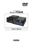
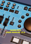
LOCATION RECORDER
PD204
Model
QUICK SET TIME
POWER
FILE SEL LIGHT
EXIT
space
ENTER
YES
1
ON
OFF
ABC
2
JKL
GHI
SHIFT
TC SET DRV,PAT CONTRAST BATT
MENU
MONO
C1
MS
L/M
R/S
5
PQRS
ACCESS
C2
LOCATE
FILE
MNO
CLEAR
PREV CUE NEXT
WXYZ
symbol
PRE REC
4
ST
AUX
DVD
7
8
CIRCLE TAKE
JAM
SLATE
FALSE START
6
TUV
ON
OFF
HDD
CUE
DEF
3
9
TONE
OFF
MIC
0
PD204 LOCATION RECORDER
MONITOR
MIN
MAX
PHONES
Owner’s Manual
PAUSE
REC
Safety Instructions/Table of contents
CAUTION
RISK OF ELECTRIC SHOCK
DO NOT OPEN
CAUTION:
TO PREVENT ELECTRIC SHOCK, MATCH WIDE
BLADE OF PLUG TO WIDE SLOT, FULLY INSERT.
ATTENTION:
CAUTION: TO REDUCE THE RISK OF ELECTRIC SHOCK,
DO NOT REMOVE COVER (OR BACK).
NO USER - SERVICEABLE PARTS INSIDE.
REFER SERVICING TO QUALIFIED SERVICE PERSONNEL.
"WARNING"
"TO REDUCE THE RISK OF FIRE OR ELECTRIC SHOCK,
DO NOT EXPOSE THIS APPLIANCE TO RAIN OR
MOISTURE."
SAFETY INSTRUCTIONS
1. Read Instructions - All the safety and operating instructions
should be read before the appliance is operated.
2. Retain Instructions - The safety and operating instructions
should be retained for future reference.
3. Heed Warnings - All warnings on the appliance and in the
operating instructions should be adhered to.
4. Follow Instructions - All operating and use instructions should
be followed.
5. Water and Moisture - The appliance should not be used near
water - for example, near a bathtub, washbowl, kitchen sink,
laundry tub, in a wet basement, or near a swimming pool, and
the like.
6. Carts and Stands - The appliance should be used only with a
cart or stand that is recommended by the manufacturer.
An appliance and cart combination should be moved with care.
Quick stops, excessive force, and uneven surfaces may cause
the appliance and cart combination to overturn.
7. Wall or Ceiling Mounting - The appliance should be mounted
to a wall or ceiling only as recommended by the manufacturer.
8. Ventilation - The appliance should be situated so that its location
or position dose not interfere with its proper ventilation.
For example, the appliance should not be situated on a bed,
sofa, rug, or similar surface that may block the ventilation
openings; or, placed in a built-in installation, such as a bookcase
or cabinet that may impede the flow of air through the ventilation
openings.
9. Heat - The appliance should be situated away from heat
sources such as radiators, heat registers, stoves, or other
appliances (including amplifiers) that produce heat.
10. Power Sources - The appliance should be connected to a power
supply only of the type described in the operating instructions
or as marked on the appliance.
11. Grounding or Polarization - The precautions that should be
taken so that the grounding or polarization means of an
appliance is not defeated.
2
Location Recorder Model PD204
POUR EVITER LES CHOCS ELECTRIQUES,
INTRODUIRE LA LAME LA PLUS LARGE DE LA
FICHE DANS LA BORNE CORRESPONDANTE DE
LA PRISE ET POUSSER JUSQU' AU FOND.
The lightning flash with arrowhead symbol, within an
equilateral triangle, is intended to alert the user to
the presence of uninsulated "dangerous voltage"
within the product's enclosure that may be of sufficient
magnitude to constitute a risk of electric shock to
persons.
The exclamation point within an equilateral triangle
is intended to alert the user to the presence of
important operating and maintenance (servicing)
instructions in the literature accompanying the
appliance.
12. Power Cord Protection - Power supply cords should be routed
so that they are not likely to be walked on or pinched by items
placed upon or against them, paying particular attention to
cords at plugs, convenience receptacles, and the point where
they exit from the appliance.
13. Cleaning - The appliance should be cleaned only with dry cloth.
14. Nonuse Periods - The power cord of the appliance should be
unplugged from the outlet when left unused for a long period
of time.
15. Object and Liquid Entry - Care should be taken so that objects
do not fall and liquids are not spilled into the enclosure through
openings.
16. Damage Requiring Service - The appliance should be serviced
by qualified service personnel when:
A. The power supply cord or the plug has been damaged; or
B. Objects have fallen, or liquid has been spilled into the
appliance; or
C. The appliance has been exposed to rain; or
D. The appliance does not appear to operate normally or
exhibits a marked change in performance; or
E. The appliance has been dropped, or the enclosure damaged.
17. Servicing - The user should not attempt to service the appliance
beyond that described in the operating instructions.
All other servicing should be referred to qualified service
personnel.
18. The appliance should be situated away from drops of water or
spray of water.
19. Objects containing liquid such as vase must not be put on the
appliance.
20. The appliance is not completely isolated from the power supply
even if the power switch is at off position.
21. Appliance shall not be exposed to dripping or splashing and
no objects filled with liquids, such as vases, shall be placed on
the appliance.
22. Only use attachments/accessories specified by the
manufacturer.
23. An appliance with a protective earth terminal should be
connected to a mains outlet with a protective earth connection.
24. An appliance should be placed in a position where an AC plug/
inlet can be easily pulled out by hand.
25. Main plug is used as the disconnection device. It shall remain
readily operable and should not be obstructed during intended
use. To be completely disconnected the apparatus from supply
mains, the mains plug of the apparatus shall be disconnected
from the mains socket outlet completely.
Safety Instructions/Table of contents
Important Safety Instructions
1)
Read these instructions.
2)
Keep these instructions.
3)
Heed all warnings.
4)
Follow all instructions.
5)
Do not use this apparatus near water.
6)
Clean only with dry cloth.
7)
Do not block any ventilation openings.
Install in accordance with the
manufacturer's instructions.
8)
Do not install near any heat sources such
as radiators, heat registers, stoves, or
other apparatus (including amplifiers) that
produce heat.
9)
Do not defeat the safety purpose of the
polarized or grounding-type plug.
A polarized plug has two blades with one
wider than the other. A grounding type
plug has two blades and a third grounding
prong. The wide blade or the third prong
are provided for your safety.
If the provided plug does not fit into your
outlet, consult an electrician for
replacement of the obsolete outlet.
10)
11)
Only use attachments/accessories
specified by the manufacturer.
12)
Use only with the cart, stand, tripod,
bracket, or table specified by the
manufacturer, or sold with the apparatus.
When a cart is used, use caution when
moving the cart/apparatus combination
to avoid injury from tip-over.
13)
Unplug this apparatus during lightning
storms or when unused for long periods
of time.
14)
Refer all servicing to qualified service
personnel. Servicing is required when the
apparatus has been damaged in any
way, such as power-supply cord or plug
is damaged, liquid has been spilled or
objects have fallen into the apparatus, the
apparatus has been exposed to rain or
moisture, does not operate normally, or
has been dropped.
Protect the power cord from being walked
on or pinched particularly at plugs,
convenience receptacles, and the point
where they exit from the apparatus.
Location Recorder Model PD204
3
Safety Instructions/Table of contents
Table of contents
Introduction of this manual ................................................................................................................11
Precautions ..........................................................................................................................................11
Cautions for use ..................................................................................................................................13
Precautions of installation .................................................................................................................13
Chapter-1: Main features .....................................................................................15
Main features and functions .........................................................................................................16
What is in the box? .........................................................................................................................19
PD204 options and related Fostex products .............................................................................19
Chapter-2: Preparation before using the PD204 ..............................................21
Preparation of power supply ........................................................................................................22
Mounting the battery .....................................................................................................................23
Important settings for using the battery .....................................................................................24
Battery priority setting (essential when using more than one battery) ....................................24
Low battery warning setting ............................................................................................................24
Power supply priority setting (essential when using both [DC-IN] and a battery) ..................25
Protector adjustment ........................................................................................................................25
Saving the battery power ...............................................................................................................26
Battery condition display ..............................................................................................................26
Dismounting the battery ...............................................................................................................27
Using [DC-IN] (Connecting the AC adaptor) ...............................................................................28
Important settings for using [DC-IN] ...........................................................................................28
Low battery warning setting ............................................................................................................28
Power supply priority setting (essential when using both [DC-IN] and a battery) ..................28
Turning on the power ....................................................................................................................29
Display backlight and contrast .....................................................................................................30
Turning on the display backlight .............................................................................................. ......30
Adjusting the display contrast ........................................................................................................30
Turning off the power ....................................................................................................................30
Internal clock setting ...........................................................................................................................31
Preparation of a DVD-RAM disk ........................................................................................................33
Inserting a disk ................................................................................................................................33
Initial format of a DVD-RAM disk .................................................................................................34
Replacing the internal hard disk drive ..............................................................................................37
4
Location Recorder Model PD204
Safety Instructions/Table of contents
Chapter-3: Names and functions .......................................................................39
Left side panel (inputs/outputs) ........................................................................................................40
Right side panel (inputs/outputs) ......................................................................................................42
Front panel ...........................................................................................................................................44
Top panel ..............................................................................................................................................52
Rear panel .............................................................................................................................................54
LCD display details .............................................................................................................................55
Home screen ....................................................................................................................................55
Time display .......................................................................................................................................55
Status information ....................................................................................................................56
File name/Next file name .........................................................................................................57
Disk remaining ..........................................................................................................................57
Current drive/file number ......................................................................................................57
Protect icon ........................................................................................................................................57
Screen examples ........................................................................................................................58
MENU list screen ..........................................................................................................................58
SYS SETUP menu screen ..............................................................................................................58
BATTERY SETUP menu screen ...................................................................................................58
TC SETUP menu screen ...............................................................................................................58
DISK UTILITY menu screen ........................................................................................................58
USB to PC menu screen ...............................................................................................................58
EDIT EDL FILE menu screen .......................................................................................................59
Audio file select screen ...............................................................................................................59
Drive select screen ......................................................................................................................59
CUE LIST screen ...........................................................................................................................59
Contrast adjustment screen .....................................................................................................59
Chapter-4: Basic connections ............................................................................61
Input connection .................................................................................................................................62
Analog audio input connection ....................................................................................................62
Digital audio input connection .....................................................................................................63
Time code input connection .........................................................................................................63
Sync signal connection ...................................................................................................................63
External audio signal connection for monitoring ......................................................................63
Output connection ..............................................................................................................................64
Analog audio output connection ..................................................................................................65
Digital audio output connection ...................................................................................................65
Time code output connection .......................................................................................................65
Word clock output connection ....................................................................................................65
Other connections ..............................................................................................................................66
USB keyboard connection ..............................................................................................................66
PC connection ..................................................................................................................................68
External controller connection .....................................................................................................68
Power connection ............................................................................................................................69
Location Recorder Model PD204
5
Safety Instructions/Table of contents
Connection examples .........................................................................................................................70
Connection example for recording (1) ........................................................................................70
Connection example for recording (2) ........................................................................................71
Chapter-5: Recording/playback .........................................................................73
Preparation before recording ............................................................................................................74
Setup for recording in quick setup mode ....................................................................................74
How to make settings in the quick setup mode .............................................................................74
Frame rate selection for LTC (or external time code) ...................................................................75
System clock reference selection ....................................................................................................75
Sampling frequency and bit length selection ................................................................................76
TC recording mode setting ..............................................................................................................76
Clock pull up/pull down setting .....................................................................................................76
Power source priority selection .......................................................................................................77
Setting in the MENU mode .............................................................................................................77
Default file name setting ..................................................................................................................77
Maximum file size setting .................................................................................................................77
Partition link setting .........................................................................................................................77
Error tone output setting .................................................................................................................78
Mixer settings ..................................................................................................................................78
Input signal selection ........................................................................................................................79
High-pass filter setting ......................................................................................................................79
Limiter setting ..................................................................................................................................79
Adjusting the input gain (for channels 1 through 4) ...........................................................80
Phase setting (for channels 1 through 4) .......................................................................................82
Controlling signals sent to the stereo bus ..............................................................................82
Monitoring recording signals ..................................................................................................83
Selecting the drive for recording ..................................................................................................84
Recording analog audio .....................................................................................................................85
Starting recording ...........................................................................................................................85
About overloading during recording .............................................................................................86
Canceling recording (False Start) .................................................................................................86
Recording in Pre rec mode .............................................................................................................87
Recording a slate tone/slate mic signal .......................................................................................88
Recording digital audio ....................................................................................................... ...............89
Selecting the sampling frequency/bit length .............................................................................89
Selecting the system clock .............................................................................................................89
Recording time code ...........................................................................................................................90
Selecting the TC frame rate ...........................................................................................................90
Selecting the TC generator mode (TC recording mode) ...........................................................90
Automatic record start by external time code ............................................................................91
Setting the time code output .........................................................................................................91
Force jam to external time code ........................................................................................................92
6
Location Recorder Model PD204
Safety Instructions/Table of contents
Cue point setting .................................................................................................................................93
Setting a cue point on the fly during audio recording ..............................................................93
Viewing the cue point list ...............................................................................................................93
Editing a cue point ..........................................................................................................................94
Editing a cue label .............................................................................................................................94
Editing cue point data .......................................................................................................................94
Deleting a cue point ..........................................................................................................................95
Adding a new cue point to the cue point list ...............................................................................95
Basic playback ....................................................................................................................................96
Normal audio playback ..................................................................................................................96
Cueing playback ..............................................................................................................................97
Time code playback ........................................................................................................................97
Skip/locate functions ........................................................................................................................98
Skipping by file .............................................................................................................................98
Skipping by cue point .................................................................................................................98
Locating to the beginning (ABS 0) of a file ................................................................................99
Locating to the end (REC END) of a file ......................................................................................99
Locating to the previous locate point ........................................................................................99
Locating to the desired time ........................................................................................................100
Locating to the desired cue point ...............................................................................................101
Chapter-6: Advanced operations .....................................................................103
Auto copy function ............................................................................................................................104
Setting a partition .........................................................................................................................104
Selecting auto copy mode ............................................................................................................105
Making auto copy .........................................................................................................................106
Disk copy function ............................................................................................................................107
Selecting source drive ..................................................................................................................107
Making disk copy ..........................................................................................................................108
File copy function ..............................................................................................................................110
Selecting source drive ..................................................................................................................110
Making file copy ............................................................................................................................111
Dual drive recording .........................................................................................................................113
Formatting in the “DDR” mode ..................................................................................................113
Making dual drive recording ......................................................................................................115
Data export to PC ...............................................................................................................................116
Connecting PC to the unit ............................................................................................................117
Location Recorder Model PD204
7
Safety Instructions/Table of contents
How to unmount the PD204 from the PC ..................................................................................117
Example of copying data to a computer hard disk ..................................................................118
Example of exporting data to a computer application ............................................................118
Chapter-7: Creating and editing ALE files (EDIT EDL FILE menu) ..............121
Creating a new ALE file .....................................................................................................................122
Adding audio file entries to an ALE file ..........................................................................................125
Viewing and editing audio file entries .............................................................................................127
Viewing audio file entries ............................................................................................................127
Adding an audio file entry to an existing ALE file ....................................................................128
Deleting an audio file entry .........................................................................................................128
Editing an ALE file .............................................................................................................................129
Editing an ALE file name ..............................................................................................................129
Remarking an ALE file ..................................................................................................................130
Deleting an ALE file .......................................................................................................................131
Chapter-8: MENU mode .....................................................................................133
About MENU mode ...........................................................................................................................134
SYS SETUP menu .............................................................................................................................136
Project name setting [Set project name] ....................................................................................137
Default file name setting [Default file name] ............................................................................138
Default track name setting [Default TrkName] ........................................................................140
Next event number setting [Next event No] ..............................................................................141
Recording FS/bit length setting [Record FS&Bit] .....................................................................142
Pull up/down setting [Pull up/down] ........................................................................................143
Digital output signal format selection [Digital out] .................................................................144
Diagnoses file setting [Diagnoses] ..............................................................................................145
Peak hold time setting [Peak hold] .............................................................................................146
Slate tone/pop tone recording mode setting [Tone rec mode] .............................................147
Pause cancel time setting [Pause time] ......................................................................................149
USB keyboard type setting [Keyboard] .....................................................................................150
Pre recording time setting [Pre rec time] ..................................................................................151
Maximum file length setting [Max file length] .........................................................................152
Continuous recording function [Auto part. link] ....................................................................153
False start mode setting [False start] ..........................................................................................155
Limiter parameter setting [Limiter parameter] .......................................................................156
8
Location Recorder Model PD204
Safety Instructions/Table of contents
ANALOG OUT nominal level setting [Stereo out level] ...........................................................158
Monitor speaker mute setting [Speaker mute] .........................................................................159
Error tone output setting [Error tone] .......................................................................................160
Chain play mode setting [Chain play] .......................................................................................163
ROM version checking [Version] ................................................................................................164
BATTERY SETUP menu ............................................................................................................ .......165
Battery low voltage warning setting [BATT. warning] .............................................................166
DC-IN low voltage warning setting [DC-IN warning] ...............................................................167
Power supply priority setting [Power priority] ........................................................................168
Battery priority setting [Active battery] ....................................................................................169
Battery setting examples .............................................................................................................170
Battery remaining time [BATT. Remain] ...................................................................................172
Battery status [BATT. status] .......................................................................................................173
TC SETUP menu ...............................................................................................................................174
System clock selection [Sync clock] ...........................................................................................175
TC frame rate selection [Frame rate] .........................................................................................176
Generator mode selection [Gen mode] .....................................................................................177
Internal TC generator setting [Set Gen. TC] ..............................................................................178
User bit setting [Set Gen Ubit] .....................................................................................................180
Jam mode setting [JAM mode] ....................................................................................................182
Time code output source selection [Sel. TC Out] .....................................................................183
Default LTC start time setting [Default LTC start] ....................................................................184
LTC start time editing [Edit LTC start] .......................................................................................185
UBIT setting of playback time code [Ref TC Ubit] ....................................................................186
Time code output while paused [Rep pause TC] ......................................................................187
Automatic recording start by external TC [Recin via ExtTC] ..................................................188
Internal TC generator power-off timer setting [TC PWR Timer] ..........................................189
DISK UTILITY menu ..........................................................................................................................190
Editing a file name [Edit file name] ............................................................................................191
Viewing a file information and editing descriptor information [File info.] .........................192
Editing descriptor information .....................................................................................................194
Adding descriptor information ....................................................................................................194
Deleting descriptor information ...................................................................................................194
Viewing iXML Chunk data information .......................................................................................195
Editing iXML Chunk data information .........................................................................................195
Deleting an unnecessary audio file [Delete file] .................................................................196
Restoring a deleted audio file [Restore Del. file] .................................................................197
Formatting a disk (or a hard disk partition) [Format] .......................................................198
Editing the reel number (Volume label) [Reel No.] ............................................................202
Record protection On/Off setting [Rec protect] ...............................................................203
Location Recorder Model PD204
9
Safety Instructions/Table of contents
Resume function On/Off setting [Resume] .........................................................................204
Partition protection On/Off setting [Part. protect] ............................................................205
HDD operating time display [HDD Ope. Time] ...................................................................206
LOAD SETUP menu ....................................................................................................................207
SAVE SETUP menu .....................................................................................................................208
Chapter-9: Specifications .............................................................................209
Inputs/outputs ..............................................................................................................................210
Recording/playback ....................................................................................................................211
General ..........................................................................................................................................211
Physical dimensions ...................................................................................................................212
Block diagram ..............................................................................................................................213
INDEX ............................................................................................................................................214
10
Location Recorder Model PD204
Introduction
Introduction of this manual
This manual is a guidebook for using the Fostex PD204 Location Recorder.
This manual is intended for users who have experience and knowledge of
using a professional digital recorder.
You may roughly understand how to use the PD204 by reading "Chapter
1: Main features" and "Chapter 3: Names and functions".
"Chapter 3: Names and functions" describes names and functions of keys,
controls and connectors, as well as reference pages. So you can refer to
this chapter as index for detail information.
"Chapter 2: Preparations before using the PD204" contains the necessary
information when using the PD204 for the first time, such as "About power
supply" and "Initial format of a DVD-RAM disk".
Precautions
•
For supplying the power to the unit from an AC outlet, only use the
Fostex authorized AC adaptor (optional).
If you use any unauthorized AC adaptor, the unit may not work
correctly and there is a serious risk of damage to the unit.
•
Make sure that the voltage of your AC power outlet matches the
voltage requirements printed on the AC adaptor.
If you wish to use the unit in a country where the voltage of the AC
power outlet does not match your AC adaptor, ask your local Fostex
dealer or service station for purchasing an appropriate AC adaptor.
Note that the AC adaptor can be used both in 50 Hz and 60 Hz areas.
•
Never supply voltage other than DC12V to the unit.
•
Only use the IDX ENDURA or NP-1 type battery (if you use the NP-1
type battery, the dedicated holder and holder plate are needed).
* IDX, IDX (logo), ENDURE, V-Mount, V-Plate, Digi-View and i-Trax are the trademarks of IDX
Company Ltd..
•
When inserting/replacing batteries or disconnecting the AC
adaptor, make sure that the unit main power is off. Otherwise,
memory data may be damaged because the unit always handles data
while the power is on.
•
While the unit is accessing to a disk, never turn off the power.
Make sure that the unit completely stops accessing to the disk
before you turn off the power. Otherwise, recorded data may be
lost, as well as the internal hard disk or DVD drive may be damaged.
<Note>: Fostex assumes no responsibility on data loss or whatsoever
due to use of the unit.
<Note>: Fostex is not responsible for any "direct damage" or "indirect
damage" caused by using the unit.
Location Recorder Model PD204
11
Introduction
•
Do not let water or other liquid, or metal objects such as pins,
accidentally enter the inside of the unit (especially inside of the disk
tray) because this may lead to electric shock or damage. Should
water enter the inside of the unit, turn off the power, unplug the AC
adaptor and remove batteries, and consult your dealer or the
nearest FOSTEX service station.
•
Do not drop the unit or give it a strong shock. Doing so may damage
the internal circuits, display or panels. Handle the unit with great
care because it is a precision mechanical device.
•
Do not open the case or touch inside the unit because of the danger
of electric shock and failure.
•
Do not give a strong shock to the LCD display. The liquid used inside
the LCD display is toxic. If the liquid is spilled, do not suck it in.
If it is stained to your hand or skin, wash immediately with plenty of
water.
•
Though the unit is designed to be used outside, it is not perfectly
waterproofed. So do not use the unit where it catches the rain or
spray directly.
<About replacing the lithium battery>
The unit contains the internal lithium battery for running the internal
clock. The battery should be replaced approximately every five years.
To replace the battery, ask your dealer or the nearest FOSTEX service
station. If the battery is not correctly replaced, there may be a risk of
explosion, etc.
<Important!>
The model name, power requirement and serial number for the PD204 are indicated on the bottom
side.
MODEL PD204
LOCATION RECORDER
FOSTEX CO.
INPUT: 12~24VDC
SERIAL NO.
MADE IN JAPAN
12
Location Recorder Model PD204
Introduction
Cautions for use
If you make recording or playback using a DVD-RAM disk, do not hang
the unit using the shoulder belt, which may damage the DVD drive.
Put the unit on a horizontal surface within the adjustable range of the
height adjustment arm.
* You can put the unit vertically when you make recording to the internal hard disk.
OPEN
LOCATE REC END
LOCATE ABS 0
OFF
LOCK
DISC IN
PANEL LOCK
REW
F FWD
PLAY
STOP
(dB/oct)
-12
-6
OFF
300
50
200
130
-12
-6
OFF
300
50
200
130
-12
-6
50
OFF
-12
300
-6
OFF
300
50
200
130
HPF
(Hz)
48V
DM
T12
48V
DM
T12
130
48V
200
DM
T12
48V
DM
T12
INPUT SEL
LINE
MIC
LINE
MIC
LINE
MIC
LINE
MIC
L
R
ANALOG OUT
ADJUST
DC-IN 12-24V
IN
USB
PC
HOST
KYBD
IN
R
ANALOG
L
ADJUST
DC-IN
12-24V
OUT
T
DC-OU
12-24V X)
A
(0.5A M
USB
PC
OUT
DIGITAL
DC-IN
1:GND
2:NC
3:NC
4:12-24V
DC-OUT
12-24V
(0.5A MAX)
DC-OUT
1:GND
2:NC
3:NC
4:12-24V
XLR
1:GND
2:HOT
3:COLD
OUT
DIGITAL
DC-OUT
DC-IN
1:GND
1:GND
2:NC
2:NC
3:NC
3:NC
4:12-24V
XLR
4:12-24V
1:GND
2:HOT
3:COLD
HOST
KYBD
Precautions on installation
•
Do not install the unit in the following conditions
* In an extremely hot or cold place
* In a moist place
* In a vibrated place
* In a dusty place
* In a strong magnetic field or near a device which generates a
magnetic field
* In the direct sunshine
* In the direct shower or rain
•
Notes on moisture condensation
When you bring the unit from a cold place to a warm place,
moisture may condense on the drive, display, panels, etc. In such a
case, leave the unit for a while until it warms up and evaporates any
moisture.
Location Recorder Model PD204
13
Introduction
14
Location Recorder Model PD204
Chapter 1: Main features
Chapter 1: Main features
Location Recorder Model PD204
15
Chapter 1: Main features
Main features and functions
•
Equipped with four analog inputs and two analog outputs as well as twochannel digital input and output. You can record signals from these inputs in
stereo. Two Aux analog inputs are also provided for monitoring the audio
track of a camera via headphones. (Note that the Aux inputs are provided for
monitoring only and you cannot record the Aux input signals.)
AUX input L, R
L
4
R
AUX IN
3
2
ANALOG IN
L
1
TIME CODE
IN
WORD
OUT
•
AUTO SEL
WORD/
VIDEO
IN
DC-IN 12-24V
OUT
Digital input/output
R
ANALOG OUT
ADJUST
ADJUST
9P-REMOTE
PARALLEL
Analog output L, R
Analog inputs 1-4
IN
OUT
DIGITAL
DC-IN
1:GND
2:NC
3:NC
4:12-24V
DC-OUT
12-24V
(0.5A MAX)
USB
PC
HOST
KYBD
ON OFF
DC-OUT
1:GND
2:NC
3:NC
4:12-24V
XLR
1:GND
2:HOT
3:COLD
Equipped with a 1.8-inch hard disk drive (80GB) and a 12-cm DVD multi
drive as standard. You can directly make recording to the hard disk partition
or DVD-RAM disk. In addition, you also can make "Auto copy", "File Copy"
and "Disk Copy" between a DVD-RAM disk and a hard disk partition, as well
as "Dual Drive Recording".
The internal hard disk drive can be replaced with the optional hard disk
drive unit (Model EX-HD1) by a user. The DVD multi drive is the slot loading
type and can accept a 4.7GB, non-cartridge DVD-RAM, DVD-R or DVD-RW
disk (only a DVD-RAM disk can be used for direct recording).
1.8-inch hard disk drive
LINE
MIC
LINE
T12
48V
MIC
LINE
T12
48V
MIC
LINE
T12
48V
MIC
INPUT SEL
48V
DM
DM
DM
DM
T12
130
200
130
200
130
200
130
200
50
300
50
300
50
300
50
300
(Hz)
-12
-6
OFF -12
-6
OFF
-12
-6
OFF
-12
-6
HPF
OFF
(dB/oct)
12-cm DVD combo drive
PANEL LOCK
DISC IN
LOCK
OPEN
REW
F FWD
PLAY
STOP
OFF
LOCATE REC END
LOCATE ABS 0
For the optional hard disk drive unit for replacement, ask your local Fostex
dealer or service station.
16
Location Recorder Model PD204
Chapter 1: Main features
•
The DVD-RAM disk format is conformed to "UDF Rev1.5", which ensures great
compatibility with personal computers.
•
The recording file format is conformed to the versatile BWF format. You can
export a recorded file including time code information to a BWF-compatible
application.
•
Can be used with the optional AC adaptor or IDX ENDURA battery (V-mount
type). You can stack up to four batteries for longer recording time.
•
Built in the internal generator with the jam sync function. The unit is equipped
with the time code input/output connectors (XLR), so you can stripe not only
the internal time code but also an external time code.
L
R
AUX IN
4
3
2
ANALOG IN
1
ADJUST
9P-REMOTE
TIME CODE
IN
WORD
OUT
PARALLEL
AUTO SEL
WORD/
VIDEO
IN
OUT
ON OFF
TIME CODE IN/OUT connectors
•
Provides the word sync function, allowing synchronization with external
digital equipment.
L
4
R
AUX IN
3
2
ANALOG IN
1
ADJUST
9P-REMOTE
TIME CODE
IN
WORD
OUT
PARALLEL
AUTO SEL
WORD/
VIDEO
IN
OUT
ON OFF
WORD/VIDEO IN and WORD OUT connectors
•
Equipped with the [USB PC] port for PC connection. You can directly connect
to a PC, allowing to mount the internal hard disk and DVD drives to the PC.
The unit also provides the [USB HOST] port for future expansion.
In addition, the [USB KYBD] port is also provided for USB keyboard
connection, which allows you to enter file names and volume labels from a
USB keyboard.
L
R
ANALOG OUT
ADJUST
DC-IN 12-24V
IN
DC-OUT
12-24V
(0.5A MAX)
USB
PC
HOST
KYBD
OUT
DIGITAL
DC-IN
1:GND
2:NC
3:NC
4:12-24V
DC-OUT
1:GND
2:NC
3:NC
4:12-24V
XLR
1:GND
2:HOT
3:COLD
USB port
Location Recorder Model PD204
17
Chapter 1: Main features
•
You can export a recorded audio file to the AVID system by creating the ALE
file.
•
The Mark/Cue function allows to store markers (cue points) during
recording. You can locate or skip to a cue point quickly.
•
The "False start" function allows to cancel recording easily.
•
"Pre Record" function allows glitch-free recording. When this function is
active, recent audio data is pooled in the buffer and recording starts from the
audio data in the buffer.
•
During recording, the audio file is automatically saved every minute in
background.
•
Equipped with the digital mixer which you can enjoy intuitive analog-like
operation.
Mixer section
•
In 24-bit/48kHz mode, you can record up to approximately 256 minutes onto
two tracks.
* The times shown above are the recording times on a DVD-RAM disk (4.7GB)
or a partition (approx. 4.5GB) of the hard disk.
•
In 24-bit mode, you can make recording with sampling frequencies of 44.1/
48 kHz, 88.2 kHz, 96 kHz, 176.4 kHz and 192 kHz.
In 16-bit mode, you can make recording with sampling frequencies of 44.1
kHz and 48 kHz.
18
Location Recorder Model PD204
Chapter 1: Main features
What is in the box?
Make sure that the box contains the following. If any of them are missing, please
contact your dealer.
PD204
1
Shoulder belt
1
Operation manual (this manual)
1
Driver software (CD)
1
PD204 options and related Fostex products
The following PD204 options and related products are available.
Ask your local Fostex dealer or sale office for details about them such as prices,
specifications, etc.
You can also get product information from our web site below.
http://www.fostex.com
Options
•
•
•
•
AC adaptor: Model AD15-4300 or AD-15C
1.8-inch hard disk drive: Model EX-HD1
Battery plate: Model EX-BP1
Soft case: Model ZP-62
Related products
•
•
•
•
•
Location recorder: Model PD606
DVD multitrack recorder: Model DV824
Portable location recorder: Model FR-2LE
Personal powered monitor: Model 6301B/BX/BE
Stereo headphones: Model T20RPMkII/T-5/T-7/T40RPMkII/T50RP
Location Recorder Model PD204
19
Chapter 1: Main features
20
Location Recorder Model PD204
Chapter 2: Preparation before using the PD204
Chapter 2: Preparation before using the PD204
This chapter explains what you should do before using the PD204 for the first time, including
power connection, internal clock setting and preparation of the DVD-RAM disk.
It also explains how to replace the internal hard disk drive.
Chapter 2 - Table of contents
Preparation of power supply .....................................................................................................22
Mounting the battery .............................................................................................................23
Important settings for using the battery .............................................................................24
Battery priority setting (essential when using more than one battery) ......................24
Low battery warning setting ..............................................................................................24
Power supply priority setting (essential when using both [DC IN] and battery) ..25
Protector adjustment ..........................................................................................................25
Saving the battery power .......................................................................................................26
Battery condition display ......................................................................................................26
Dismounting the battery .......................................................................................................27
Using [DC IN] (Connecting the AC adaptor) .......................................................................28
Important settings for using [DC IN] ....................................................................................28
Low battery warning setting ..............................................................................................28
Power supply priority setting (essential when using both [DC IN] and battery) ..28
Turning on the power ............................................................................................................29
Display backlight and contrast .............................................................................................30
Turning on the display backlight ......................................................................................30
Adjusting the display contrast ..........................................................................................30
Turning off the power ............................................................................................................30
Internal clock setting ..................................................................................................................31
Preparation of a DVD-RAM disk ................................................................................................33
Inserting a disk ........................................................................................................................33
Initial format of a DVD-RAM disk .........................................................................................34
Replacing the internal hard disk drive .....................................................................................37
Location Recorder Model PD204
21
Chapter 2: Preparation before using the PD204
Preparation of power supply
The unit can operate on the mobile IDX ENDURA or NP-1 type battery, as well as the dedicated
AC adaptor.
IDX ENDURA battery
NP-1 type battery
Holder and holder plate for the NP series
Dedicated AC adaptor (optional)
<Note>: The IDX ENDURA battery, NP-1 type battery (including the holder and holder
plate) and AC adaptor are not included with the unit. For the information about the
AC adaptor, ask your dealer or the nearest FOSTEX service station.
<Note>: In general, a battery is not charged when shipped. Therefore, before using
the battery, you must charge it according to the manual of the battery (note that the
PD204 does not provide the battery charge function). Also note that you must handle
the battery correctly according to the manual of the battery.
<Note>: You can mount the NP-1 battery housed in the dedicated holder to the
PD204 without any special parts, however, the holder projects from the PD204 body.
If you want to mount the NP-1 battery housed in the dedicated holder to the PD204
without projecting from the PD204 body, the optional mounting hardware (Model
EX-BP1) is needed. Ask your dealer or the local Fostex service station for installing
the mounting hardware. The mounting hardware must be installed by Fostex service
station.
* IDX, IDX (logo), ENDURE, V-Mount, V-Plate, Digi-View and i-Trax are the trademarks of IDX Company Ltd..
22
Location Recorder Model PD204
Chapter 2: Preparation before using the PD204
Mounting the battery
The ENDURA battery is mounted to the bottom of the PD204.
There are two mounts for mounting the batteries. If you use the non-PowerLink type
batteries, you can mount one battery for each base. If you use the PowerLink type
batteries, you can mount up to four batteries (two batteries for each base).
<Note>: When you mount or replace the battery, make sure that the unit power is off.
By sudden power failure, memory data may be reset or the unit may be damaged because the unit handles data while the power is on. However, note that, if you set two
batteries, you can replace a battery which is not currently active.
<Note>: If you use the IDX ENDURA battery, read the operation manual supplied with
the battery and handle it correctly. The PD204 does not provide battery charge function. Charge the IDX ENDURA battery correctly according to the battery manual.
Battery mount 2 (BATT2)
Battery mount 1 (BATT1)
Connectors
ENDURA battery
ENDURA battery
<Example of mounting the ENDURA batteries to the both battery mounts>
Location Recorder Model PD204
23
Chapter 2: Preparation before using the PD204
When you use PowerLink batteries, you
can mount up to four batteries (two batteries for each base, as shown on the
right).
<Note>: When you mount four batteries, you cannot use the protector on the
bottom panel. Use the unit horizontally.
<Notes for using PowerLink batteries>
• When you use PowerLink batteries, use batteries of the same charging
condition. If the charging conditions are significantly different, the PowerLink
function may not operate correctly resulting the PD204 powered off.
• You cannot mount more than two batteries. Each battery mount can accept up
to two batteries.
Important settings for using the battery
Battery priority setting (essential when using more than one battery)
When you use two batteries or four PowerLink batteries, you must set the battery
priority (BATT1 or BATT2).
You can specify the battery to be used preferentially. When the preferential battery
gets empty, the display shows the warning popup window and the other battery automatically takes over.
You can make setting via the quick setup mode or via the "Active battery" item in the
"BATTERY SETUP" menu of the MENU mode (see pages 77 and 169).
Low battery warning setting
Whether you use a battery with or without BMS (Battery Management System), you
can set the threshold voltage for warning low battery.
When the battery voltage gets lower than the threshold voltage you set, the warning
tone is output from the headphones connected to the unit.
By default, the threshold voltage is set to 13.2V for battery with BMS or 13.0V for
battery without BMS. However, you can set the desired threshold voltage via the "BATT.
warning" item in the "BATTERY SETUP" menu of the MENU mode (see page 166).
<Note>: When you use a battery with BMS (Battery Management System), you can check
the battery information via the "BATT. status" item in the "BATTERY SETUP" menu of
the MENU mode (see page 173).
<Note>: When you use a battery with BMS (Battery Management System), you can check
the remaining time until the battery voltage reaches the threshold voltage in one-minute
steps via the "BATT. Remain" item in the "BATTERY SETUP" menu of the MENU mode
(see page 172).
<Note>: While the battery has power, the output voltage is between 13 V to 15 V. When
the remaining power gets short, the output voltage rapidly drops. Therefore, to replace
the battery well in advance, we recommend setting the threshold voltage to 13 V or
around.
24
Location Recorder Model PD204
Chapter 2: Preparation before using the PD204
Power supply priority setting (essential when using both [DC IN] and a battery)
When you use both a battery and the [DC IN] connector, you must set the power
supply priority ("DC-IN" or "BATT"). For example, if you set it to "DC-IN", the battery
automatically takes over only when the power supply from the "DC-IN" jack is cut off
(power failure, disconnection, etc).
Note that, if you use only batteries, you do not need to make this setting.
You can make setting via the "Power priority" item in the "BATTERY SETUP" menu of
the MENU mode (see page 168).
Protector adjustment
When the battery is mounted, pull out the protector to protect the battery, as shown
below. While sliding the [ADJUST] levers on left and right side panels to the arrow
direction, pull out the protector. There are two locked positions for the protector.
Set it to the appropriate position. Note that you should push it down when replacing
the battery.
E
OUT
ADJUST
Protector
[ADJUST] levers
<Note>: The protector can protect the IDX ENDURA-7 and ENDURA-7S. When you
use the ENDURA-10 or ENDURA-10S, or PowerLink is active, we recommend using
the PD204 horizontally.
Location Recorder Model PD204
25
Chapter 2: Preparation before using the PD204
Saving the battery power
The PD204 offers the following measures for saving the battery power to extend the
battery life.
•
Pressing the [STOP] key stops the disk rotation to save the power consumption.
It is also possible to set the desired pause release time using the "Pause time" item in
the SYS SETUP menu of the MENU mode (the default pause time is three minutes).
•
When the internal monitor speaker is not used or when a headphone plug is inserted
to the [PHONES] jack, no power is supplied to the amplifier for the speaker.
The following describes some tips for saving the battery power, as well as some notes on
using the battery.
•
When you do not operate the unit on battery power for a long period of time, remove
the battery. Even if the [POWER] switch is set to "OFF", a small amount of electric
power is consumed.
•
Set the monitor level as lower as possible (regardless of whether using headphones
or the internal monitor speaker).
•
You should use the display backlight only when needed.
•
When you do not use a DVD-RAM disk, remove the disk.
•
The load impedance connected to PD204 output connectors should be greater than
10k ohm.
•
When converting a balanced output to an unbalanced output, you should not
connect the unused pin to the ground pin and leave it open. Though it lowers the
output level by 6dB, it does not influence to the audio characteristics.
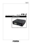
You can check the current battery remaining amount in realtime by following the procedure described below.
Battery condition display
You can check the battery remaining amount in realtime from the [ST BUS] bargraph
meters beside the LCD display on the front panel.
By pressing and holding down the [EXIT/BATT] key when you use a BMS battery and
the display shows the Home screen (in stop, playback or record mode), the [ST BUS]
bargraph meters show the battery remaining amount in % and the display pops up the
battery power voltage in V. Releasing the [EXIT/BATT] key returns the meters to the
stereo buss level monitoring and dismiss the popup window).
When you use a non-BMS battery, only the display pops up the battery power voltage.
[ST BUS] bar-graph meters
EXIT
[EXIT / BATT] key
BATT
QUICK SET TIME
POWER
FILE SEL LIGHT
EXIT
space
ENTER
YES
1
ON
OFF
SHIFT
TC SET DRV,PAT CONTRAST
BATT
MENU
MONO
C1
MS
L/M
R/S
HDD
DVD
PD204 LOCATION RECORDER
MONITOR
MAX
PHONES
26
Location Recorder Model PD204
5
PQRS
ACCESS
C2
7
LOCATE
FILE
CLEAR
PREV CUE NEXT
WXYZ
symbol
CIRCLE TAKE
PAUSE
REC
JAM
SLATE
FALSE START
6
TUV
Shows the
BATT1
remaining
amount
8
CUE
DEF
MNO
3
JKL
PRE REC
4
ST
AUX
MIN
ABC
2
GHI
9
0
ON
OFF
TONE
OFF
MIC
Shows the
BATT2
remaining
amount
Chapter 2: Preparation before using the PD204
Dismounting the battery
To dismount the battery, make sure that the power is off, and remove the battery
while pressing the release button on the IDX ENDURA battery or press down the eject
lever on the PD204.
Eject lever on the PD204
Eject lever on the PD204
Release button
<Note>: Dispose the used battery properly (see the instruction manual of your battery).
Keep the removed battery away from children.
Location Recorder Model PD204
27
Chapter 2: Preparation before using the PD204
Using [DC-IN] (Connecting the AC adaptor)
You can connect the AC adaptor or another appropriate power source to the [DC IN]
connector on the left side panel of the PD204. If you use the AC adaptor, insert the
XLR-4-32 type connector of the AC adaptor to the [DC IN] connector until it is locked,
then connect the AC plug to the AC main outlet (see the figure below).
<Notes>
• When you connect or disconnect the connector, make sure that the power is off.
• Use only the Fostex dedicated AC adaptor. Using another AC adaptor may damage
the PD204 due to the mismatch of the power voltage, polarity, etc. When connect or
disconnect the AC adaptor, make sure that the [POWER] switch is set to "OFF".
The AC adaptor for the PD204 is optionally available (ask your local Fostex dealer or
sale office for purchasing the option).
L
ADJUST
R
ANALOG OUT
DC-IN
12-24V
IN
USB
PC
OUT
DIGITAL
DC-IN
1:GND
2:NC
3:NC
4:12-24V
DC-OUT
12-24V
(0.5A MAX)
HOST
KYBD
DC-OUT
1:GND
2:NC
3:NC
4:12-24V
XLR
1:GND
2:HOT
3:COLD
[DC IN] connector
AC adaptor
To the AC main outlet
Important settings for using [DC IN]
Low battery warning setting
When you get the power from the [DC IN] connector (such as use the AC adaptor), you
can set the threshold voltage for warning low battery.
When the DC-IN voltage gets lower than the threshold voltage you set, the warning
tone is output from the headphones connected to the unit.
By default, the threshold voltage is set to 13.0V. However, you can set the desired
threshold voltage via the "DC-IN warning" item in the "BATTERY SETUP" menu of the
MENU mode (see page 167).
Power supply priority setting (essential when using both [DC IN] and battery)
When you use both a battery and the [DC IN] connector, you must set the power
supply priority ("DC-IN" or "BATT"). For example, if you set it to "DC-IN", a warning
message pops up on the display and the battery automatically takes over only when
the power supply from the "DC-IN" jack is cut off (power failure, disconnection, etc).
Note that, if you use only batteries, you do not need to make this setting.
You can make setting via the "Power priority" item in the "BATTERY SETUP" menu of
the MENU mode (see page 168).
28
Location Recorder Model PD204
Chapter 2: Preparation before using the PD204
Turning on the power
After mounting the battery or connecting the power source such as the AC adaptor to
the [DC IN] connector, you can turn on the power by setting the [POWER] switch to
"ON". The unit starts up and the screen similar to below appears (the screen example
below shows the one the first time you turn on the power after purchasing the unit).
[POWER] switch
QUICK SET TIME
POWER
FILE SEL LIGHT
EXIT
space
ENTER
YES
1
ON
OFF
ABC
2
GHI
SHIFT
TC SET DRV,PAT CONTRAST BATT/
MENU
4
MONO
L/M
R/S
5
PQRS
ACCESS
C2
C1
MS
LOCATE
FILE
CLEAR
PREV CUE NEXT
PRE REC
ST
AUX
DVD
7
8
CIRCLE TAKE
JAM
SLATE
PAUSE
REC
FALSE START
6
TUV
WXYZ
symbol
ON
OFF
HDD
CUE
DEF
MNO
3
JKL
9
TONE
OFF
MIC
0
PD204 LOCATION RECORDER
MONITOR
OFF
MAX
PHONES
This screen shows the current drive is partition 01 of the internal hard disk and there
is no file recorded in the partition. The screen also shows the next file name and
remaining recordable time of the partition.
The next file name is the name of the file which is created when you start recording. By
default, "Scene_001.wav" is automatically given to the file. You can specify the desired
name instead of this default name using the "Default file name" item in the "SYS SETUP"
menu of the MENU mode (see page 138).
The internal hard disk has been formatted when shipped. So you can make recording
to the partition in this condition. The hard disk is divided into 16 partitions (approximately 4.5GB per partition). If you want to record a file to another partition, select the
desired partition by using the drive selection function (see page 84).
<Note>: If you make recording to a DVD-RAM disk, you must format the disk (see page
34) and select the DVD-RAM drive by using the drive selection function.
<Note>: When the power is being supplied from a battery, the [BATT1] or [BATT2]
indicator on the top panel lights, while the "POWER" area on the display shows "BATT1"
or "BATT2". These depend on the settings of the "Active battery" and "Power priority"
items in the "BATTERY SETUP" menu of the MENU mode.
Battery indicators
When the power is being supplied from the [DC IN] connector,
both battery indicators on the top panel are unlit, while the
"POWER" area on the display shows "DC-IN".
Location Recorder Model PD204
29
Chapter 2: Preparation before using the PD204
Display backlight and contrast
[LIGHT / CONTRAST] key
[SHIFT] key
[MENU] dial
QUICK SET TIME
POWER
FILE SEL LIGHT
EXIT
space
ENTER
YES
1
ON
OFF
MENU
MONO
L/M
R/S
HDD
DVD
LOCATE
MNO
CLEAR
PREV
PRE RE
4
5
PQRS
ACCESS
C2
C1
MS
DEF
3
JKL
GHI
TC SET DRV,PAT CONTRAST BATT/
SHIFT
ST
AUX
ABC
2
7
6
TUV
8
WXYZ
9
symbol
0
PD204 LOCATION RECORDER
MONITOR
Turning on the display backlight
Turns on or off the backlight of the display.
Pressing the [LIGHT/CONTRAST] key turns on the backlight of the display, which is
automatically turned off after three seconds. If you keep holding down the [LIGHT/
CONTRAST] key for more than three seconds, the display shows "--Light on hold--" and
the backlight keeps on lighting until you press this key again.
<Note>: When you operate the unit on battery, we recommend not using the display
backlight unless necessary, because the backlight consumes the battery power.
Adjusting the display contrast
The display contrast is adjusted appropriately when shipped. However, you can adjust
it as your favor by the following procedure after turning on the power.
1)
Press the [SHIFT] key to enter shift mode, followed by the [LIGHT/CONTRAST] key.
The display shows the popup screen for adjusting the display contrast.
2)
Use the [MENU] dial to adjust the display contrast.
Rotating the [MENU] dial clockwise weakens the contrast while rotating the dial counter
clockwise strengthens the contrast.
3)
Press the [ENTER/YES] key to confirm the setting.
The display contrast is set.
The popup screen is dismissed and the unit exits the contrast adjustment mode.
Turning off the power
Before you turn off the power, make sure that the unit stops access to the drive.
To turn off the power, switch the [POWER] switch to the OFF position.
The display backlight flashes weakly and slowly. This indicates that the internal TC generator is still working after turning off the main unit.
The time until the TC generator turns off is set to five minutes by default, however, you can
set it to the desired time via the "TC PWR Timer" item in the "TC SETUP" menu of the MENU
mode (see page 189).
30
Location Recorder Model PD204
Chapter 2: Preparation before using the PD204
Internal clock setting
The PD204 offers realtime clock.
The realtime clock data is used for a default file name when creating a new audio file on a disk,
the file creation date/time information, the time code start time when recording a time code by
the internal time code generator, and so on (see Notes below) .
The realtime clock is adjusted according to the local time when shipped, therefore, set the time
to your local time before using the PD204 by following the procedure below.
<Note>: The realtime clock date is used for the default file name of a newly created file
when the file name mode is set to "DATE" using the "Default file name" item in the "SYS
SETUP" menu of the MENU mode (see page 138).
The following shows the Home screen examples which are shown when the file name
mode is set to "DATE". While stopped, "<DATE>.wav" is shown in the NEXT field. During
recording or playback, the file name (based on the realtime clock data) given to the current file is shown. (During playback, the remaining time is not shown.)
File name
<Home screen while stopped>
<Home screen during recording>
<Note>: Only when the TC GEN mode is set to "24H RUN", the realtime clock data is used
as the TC start time (see pages 76 and 177 for details about the TC GEN mode).
The following procedure assumes that partition 1 (PT01) which has no recorded file is currently selected.
1)
While the unit is stopped, press the [SHIFT] key to enter shift mode, followed by the
[ENTER/YES] key.
The unit enters MENU mode and brings up the MENU list screen for selecting the desired
main menu.
2)
While "SYS SETUP" is highlighted, press the [ENTER/YES] key.
The display shows the SYS SETUP menu screen, on which you can select system setup
menu item.
Location Recorder Model PD204
31
Chapter 2: Preparation before using the PD204
3)
Use the [MENU] dial to select "Adjust RTC" and press the [ENTER/YES] key.
The display now shows current internal clock time which runs in realtime.
By pressing the [ENTER/YES] key while "SET "00s":" is highlighted (as the screen shown
above right), the second field is reset to "00". If you reset the second field when the
second value is 30 or more, the minute field value is incremented. If you reset the second
field when the second value is less than 30, only the second field is reset.
4)
Use the [MENU] dial to select "EDIT" and press the [ENTER/YES] key.
The clock data at the moment when you press the [ENTER/YES] key is held and you can
now edit it (the second field flashes).
Flashing
5)
Enter the desired date/time data.
Use the [MENU] dial (or the alphanumeric keys) to enter a desired value to the current
cursor position (flashing field).
] and [
] keys.
You can move the cursor position using the [
6)
After entering date/time data, move the cursor to the offset time value (by default, "+0:00")
of Time Zone, and enter the desired offset time according to the country where the unit is
used.
By rotating the [MENU] dial, you can select the desired offset time within the range
between -12:00 and +13:00.
Example: London: +0:00, Tokyo: +9:00, Los Angels: -8:00 (-7:00)
Flashing
7)
After entering all data, press the [ENTER/YES] key to start running the clock.
<Note>: We recommend entering a time shortly ahead of "now" (such as one
minute ahead) in step 5 above and pressing the [ENTER/YES] key (in step 7
above) at the moment when the current time reaches the entered time.
8)
32
Press the [EXIT] key repeatedly to exit the MENU mode.
Location Recorder Model PD204
Chapter 2: Preparation before using the PD204
Preparation of a DVD-RAM disk
The internal DVD multi drive of the PD204 features a slim drive and accepts a non-cartridge
DVD-RAM disk (4.7GB, 2-3 x or more than 3x). An unused DVD-RAM disk must be formatted in
UDF 1.5.
Inserting a disk
The following procedure assumes that partition 1 (PT01) which has no recorded file is
currently selected.
1)
Slide the [OPEN] lever to the right.
The cover of the disk tray opens a little, so you can open the cover by hand.
PANEL LOCK
DISC IN
LOCK
REW
F FWD
OFF
OPEN
OPEN
QUICK SET TIME
POWER
FILE SEL LIGHT
EXIT
space
ENTER
YES
1
TC SET DRV,PAT CONTRAST BATT/
SHIFT
2)
MENU
MONO
L/M
LOCATE
FILE
CLEAR
PREV CUE NEXT
WXYZ
symbol
PRE REC
4
5
JAM
SLATE
6
PQRS
ACCESS
C2
C1
CUE
DEF
MNO
3
JKL
GHI
ST
AUX
ABC
2
ON
OFF
TUV
ON
OFF
HDD
DVD
7
8
9
0
Insert a disk to the drive slot.
The unit loads the disk and reads the disk information.
When the unit is shipped from the factory, the current drive is set to the internal hard
disk drive, so the display shows the Home screen for partition 1. Therefore, the screen
does not change when loading a DVD-RAM disk.
To eject the disk, press the eject button located at the left of the slot.
<Note>: Do not eject a DVD disk from the disk tray while the current drive is set to
the DVD drive and the disk is running. Before you eject the disk, make sure that
the disk is stopped (the [PAUSE] indicator is unlit).
Also note that it takes some time to eject the disk. Do not press the [PLAY], [F.
FWD] or [REW] key.
Eject button
QUICK SET TIME
POWER
FILE SEL LIGHT
EXIT
space
ENTER
YES
1
ON
OFF
3)
TC SET DRV,PAT CONTRAST BATT/
MENU
C1
MS
L/M
R/S
5
PQRS
ACCESS
MONO
LOCATE
MNO
CLEAR
WXYZ
symbol
CU
FILE
PREV CUE NEXT
PRE REC
4
ST
C2
DEF
3
JKL
GHI
SHIFT
AUX
ABC
2
JAM
SLAT
6
TUV
ON
OFF
HDD
DVD
7
8
9
0
Close the tray cover until locked by hand.
Now you can format the DVD-RAM disk by following the procedure described on the next
page.
Location Recorder Model PD204
33
Chapter 2: Preparation before using the PD204
Initial format of a DVD-RAM disk
1)
While the unit is stopped, press the [SHIFT] key to enter shift mode, followed by the
[ENTER/YES] key.
The unit enters MENU mode and brings up the MENU list screen for selecting the desired
main menu.
2)
Use the [MENU] dial to select "DISK UTILITY" and press the [ENTER/YES] key.
The display shows the DISK UTILITY menu screen, on which you can select disk utility
menu item.
3)
Use the [MENU] dial to select "Format" and press the [ENTER/YES] key.
The display now shows the screen for formatting.
On this screen, you can make the following four settings.
This procedure example assumes that the "Reel No" and "Physical Format" items are left
as default.
Drive
Selects the drive to be formatted.
You can select "DVD-RAM" or any of the hard disk partitions ("PT01HD" through
"PT16HD").
Sets the reel number for the DVD-RAM disk or partition to be formatted.
The default reel numbers for a DVD-RAM disk and partitions are as follows.
Reel No
DVD-RAM: S001
Partitions: S002 through S017
You can change the reel number later via the "Reel No" item in the "DISK UTILITY"
menu of the MENU mode (see page 202).
34
Format
Mode
Selects the format mode.
When you format a DVD-RAM disk, only "Normal" is available.
When you format a partition, "Normal" and "DDR" are available. The "DDR" option is
used when executing dual drive recording described later (see page 113).
Physical
Format
Selects whether or not you physically format a DVD-RAM disk or partition.
When selecting "Off", a quick format is performed.
When selecting "On", a physical format is performed, which takes longer time (see
<Note> on the next page).
Location Recorder Model PD204
Chapter 2: Preparation before using the PD204
<Note>: When formatting a well-used DVD-RAM disk, perform the physical format. The following shows the approximate required time for formatting a 4.7GB
DVD-RAM disk.
When "Physical Format" is set to "Off":
When "Physical Format" is set to "On":
4)
approx. 1 min. 30 sec.
approx. 1 hour 30 min.
Press the [ENTER/YES] key.
You can now select the drive.
Flashing
5)
Use the [MENU] dial to select "DVD-RAM" and press the [ENTER/YES] key.
The drive selection is confirmed and "Reel No: [S001" is highlighted.
Flashing
For the operation of setting the desired reel number on this screen, see the next page.
Also, you can set the desired reel number after formatting via the "Reel No" item in the
"DISK UTILITY" menu of the MENU mode (see page 202).
6)
Use the [MENU] dial to highlight "[EXECUTE]" and press the [ENTER/YES] key.
The display shows the caution screen, where "Are you sure?" flashes.
Flashing
7)
While "Are you sure?" flashes, press the [ENTER/YES] key.
The unit starts formatting.
The display shows the formatting countdown, as well as the progress status by the
bar-graph meter. When formatting completes, the display shows "Fmt. Completed!".
<Note>: Note that the formatting countdown and bar-graph meter show the approximate information. Do not proceed to the next step until "Fmt. Completed!"
is shown.
Location Recorder Model PD204
35
Chapter 2: Preparation before using the PD204
<Note>: In rare cases, the unit shows "Disk error!" and releases the disk lock after
formatting is performed. In such a case, set "Physical Format" to "On" and format
the disk again. If "Disk error!" is shown again after the physical format is performed, do not use the disk.
8)
After formatting, press the [EXIT] key to exit the MENU mode.
The display returns to the Home screen previously shown before entering the MENU
mode.
To make recording to the DVD-RAM disk, select the current drive to the DVD drive (see
page 84 for details).
<Note>: If you format a DVD-RAM disk when any partition is selected as the current drive, the current drive does not change after formatting is completed.
Therefore, if you want to make recording to the DVD-RAM disk, you must change
the current drive from the partition to the DVD drive.
On the other hand, if you format a partition when the DVD drive is selected as the
current drive, the current drive automatically changes to the partition after formatting is completed.
How to set the desired reel number
During the process of initial formatting, you can set the desired reel number by the
following procedure.
1)
While "Reel No: [S001" is highlighted, press the [ENTER/YES] key.
The first digit of the reel number field starts flashing. You are ready for editing the
reel number.
flashing
2)
Use the [MENU] dial (or the alphanumeric keys) to enter the desired reel number.
Use the [
] and [
] keys to move the cursor position when entering the number
using the [MENU] dial.
When using the alphanumeric keys for entering characters, pressing any other
alphanumeric key moves the cursor to the right automatically.
Pressing the [CLEAR] key clears the character at the cursor position.
3)
36
After editing the reel number, press the [ENTER/YES] key to confirm your setting.
Location Recorder Model PD204
Chapter 2: Preparation before using the PD204
Replacing the internal hard disk drive
You can replace the internal hard disk drive with the optional Model EX-HD1 hard disk drive by
following the procedure below.
<Note>: Before you replace the hard disk drive, turn off the power and remove the AC
adaptor (or battery). Handle the optional and internal hard disk drives gently and carefully because they contain precision parts.
<Note>: When you use the unit vertically with the front panel down, put the unit on a soft
fabric, etc. and fix the unit so that it does not fall down.
Optional hard disk drive (Model EX-HD1)
<Note>: The optional hard disk is formatted when
shipped so you do not have to format it after mounting
it to the PD204.
1)
Loosen the four fixed screws around battery mount 1 and remove the panel.
The internal hard disk drive appears as indicated in the figure below.
Fixed screw 1
Fixed screw 2
Fixed screw 3
Fixed screw 4
Internal hard disk drive
2)
Loosen the two fixed screws which fixes the hard disk drive and remove the hard disk drive.
The fixed screws are not removed. Grip the screw heads by fingers and pull out the hard
disk drive. The drive is connected to the connector inside so take great care for pulling it
out.
Location Recorder Model PD204
37
Chapter 2: Preparation before using the PD204
Fixed screw 1
Fixed screw 2
After removing the hard disk drive, you can see the connector inside for connecting with
the hard disk drive.
Connector
3)
Insert the optional hard disk drive to the slot.
Insert the drive into the slot until it is fully inserted to the connector inside, and fix it with
two screws.
4)
Cover the slot with the panel and fix it with four screws.
Now you finish hard disk drive replacement.
38
Location Recorder Model PD204
Chapter 3: Names and Functions
Chapter 3: Names and Functions
Chapter 3 - Table of contents
Left side panel .............................................................................................................................40
Right side panel ...........................................................................................................................42
Front panel ..................................................................................................................................45
Top panel .....................................................................................................................................53
Rear panel ...................................................................................................................................55
LCD display details .....................................................................................................................56
Location Recorder Model PD204
39
Chapter 3: Names and Functions
Left side panel (inputs/outputs)
1
L
12
ADJUST
R
ANALOG OUT
DC-IN
12-24V
IN
USB
1.
HOST
KYBD
9 8 7
11 10
OUT
DIGITAL
DC-IN
1:GND
2:NC
3:NC
4:12-24V
DC-OUT
12-24V
(0.5A MAX)
PC
3
2
6
DC-OUT
1:GND
2:NC
3:NC
4:12-24V
XLR
1:GND
2:HOT
3:COLD
4
5
[ANALOG OUT (L, R)] connectors (XLR-3-32 type/balanced)
Outputs the stereo tracks L/R signals. It is used to connect to an external audio
device. The reference level is set to +4dBu by default but you can change it to
-10dBu or -60dBu using the "Stereo out level" menu item in the "SYS SETUP" menu
of the MENU mode (see page 158).
2
1
1
2
3
GND
HOT
COLD
3
2.
[DIGITAL IN] connector (XLR-3-31 tyep/balanced)
This connector recieve AES/EBU or S/P DIF digital signals.
It automatically detects the digital audio input format (AES/EBU or S/P DIF).
1
2
1
2
3
GND
HOT
COLD
3
3.
[DIGITAL OUT] connector (XLR-3-32 tyep/balanced)
This connector sends AES/EBU or S/P DIF digital signals.
The digital output signal format (AES/EBU or S/P DIF) can be set by the “Digital out”
menu item in the “SYS SETUP” menu of the MENU mode (see page 144).
2
1
3
40
Location Recorder Model PD204
1
2
3
GND
HOT
COLD
Chapter 3: Names and Functions
4.
Handle
Used to fix the supplied shoulder belt.
5.
Angle adjustment arm
Used to adjust the angle of the unit when you use it on a desk.
IN
OUT
DIGITAL
DC-IN
1:GND
2:NC
3:NC
4:12-24V
DC-OUT
1:GND
2:NC
3:NC
4:12-24V
XLR
1:GND
2:HOT
3:COLD
IN
R
OUT
ANALOG
L
ADJUST
DC-IN
V
12-24
UT
DC-O
V
12-24 X)
MA
(0.5A
USB
PC
6.
OUT
L
DIGITA
DC-OUT
DC-IN
1:GND
1:GND
2:NC
2:NC
3:NC
3:NC
4:12-24V
XLR
4:12-24V
1:GND
2:HOT
3:COLD
HOST
KYBD
Internal monitor speaker
Outputs audio signals of tracks L and R, error tones, etc.
When a headphones plug is inserted to the [PHONES] jack, the monitor speaker is
inactive.
7.
[USB HOST] connector (Series A Receptacle/USB 2.0 High speed)
Not currently supported. Prepared for the future expansion.
1
2
3
1
2
3
4
4
VBUS
DD+
GND
<Note>: When you connect the PD204 to a personal computer using the [USB
PC] connector, do not connect any device to the [USB HOST] connector.
8.
[USB KYBD] connector (Series A Receptacle/USB 1.1)
Used to connect to a USB keyboard. You can control the PD204 from the keyboard
(see “Connection examples of a keyboard” on page 66).
1
9.
2
3
1
2
3
4
4
VBUS
DD+
GND
[USB PC] connector (Series B Receptacle)
Used to connect to a personal computer. You can transfer audio files between the
PD204 and your personal computer (see pages 68 and 116).
<Note>: When you connect the PD204 to a personal computer using the [USB
PC] connector, do not connect any device to the [USB HOST] connector.
10.
[DC IN 12-24V] connector (XLR-4-32 type/male)
Connects the optional AC adaptor or an external battery.
1
4
3
2
1
2
3
4
GND
NC
NC
12-24V
Location Recorder Model PD204
41
Chapter 3: Names and Functions
11.
[DC OUT] connectors (Hirose 4-pin, HR10A-7R-4S type/female)
Outputs DC 12 V/0.5 A power. You can supply power to an external device.
4
2
3
12.
1
2
3
4
1
GND
NC
NC
12-24V
[ADJUST] lever
Used to adjust the protector on the left of the rear panel (see page 25).
Right side panel
2
1
11
L
R
AUX IN
4
3
2
ANALOG IN
1
ADJUST
9P-REMOTE
TIME CODE
IN
WORD
OUT
PARALLEL
10
1.
AUTO SEL
WORD/
VIDEO
IN
9
3
OUT
ON OFF
7 6 5
8
4
[AUX IN (L, R)] connectors (XLR-3-31 type/balanced)
These connectors receive analog audio signals from the external device.
1
2
1
2
3
GND
HOT
COLD
3
2.
[ANALOG IN (1 ~ 4)] connectors (XLR-3-31 type/balanced)
These connector receive analog audio signals (mic or line level), which can be sources
of channels 1 through 4.
1
2
1
2
3
GND
HOT
COLD
3
3.
[ADJUST] lever
Used to adjust the protector on the right of the rear panel (see page 25).
42
Location Recorder Model PD204
Chapter 3: Names and Functions
4.
[TIME CODE OUT] connector (XLR-3-32 type/balanced)
Outputs time code.
2
1
GND
HOT
COLD
1
2
3
3
5.
[TIME CODE IN] connector (XLR-3-31 type/balanced)
Inputs external time code.
1
2
GND
HOT
COLD
1
2
3
3
6.
[WORD IN] termination switch
Terminates the word input signal by setting the switch to "ON".
7.
[WORD/VIDEO IN] and [WORD OUT] connectors (BNC type)
The [WORD/VIDEO IN] connector receives word or video clock. It automatically
detects the clock type (word or video).
The [WORD OUT] connector feeds a word clock.
8.
[9P-REMOTE] connector (D-sub 9-pin/female)
Not currently supported. Prepared for the future expansion.
9.
Angle adjustment arm
10.
[PARALLEL] connector (MINI DIN 8-pin)
This connector accepts parallel remote signals for controlling the PD204 externally.
You can control the following nine operations remotely.
1
PLAY
6
CUE point registration
2
STOP
7
PAUSE
3
RECORD
8
FILE
4
REWIND
9
FILE
5
F. FORWARD
<Operation>
When each terminal is grounded, the corresponding function is active.
Note that you can always control the PD204 via this connector regardless of the setting of the [PANEL LOCK] key on the panel.
8 7 6
5
4 3
2 1
1
2
3
4
5
6
7
8
PLAY
STOP
REC
GND
SHIFT
REW
DC-OUT
FF
SHIFT + STOP
SHIFT + REC
SHIFT + REW
SHIFT + FF
CUE
PAUSE
FILE
FILE
(*) V BATT (12V), Max 500mA.
It is output regardless of power on/off.
Location Recorder Model PD204
43
Chapter 3: Names and Functions
<Caution>: Pin 7 (DC-12V) is supplied from the PD204.
If it is short-circuited to GND or used with a heavy load, the PD204 internal
battery life may be exhausted faster or the PD204 may generate heat abnormally. Be careful not to use it with a heavy load or short-circuit it to GND.
11.
Handle
Used to fix the supplied shoulder belt.
Front panel
2
4
1
3
QUICK SET TIME
POWER
6
5
8
7
FILE SEL LIGHT
EXIT
9
space
ENTER
YES
1
ON
OFF
SHIFT
27
ABC
2
GHI
TC SET DRV,PAT CONTRAST BATT
MENU
MONO
C1
MS
L/M
R/S
JKL
5
PQRS
ACCESS
C2
CUE
DEF
LOCATE
FILE
MNO
CLEAR
PREV CUE NEXT
WXYZ
symbol
DVD
7
8
PAUSE
REC
JAM
SLATE
FALSE START
6
TUV
ON
OFF
HDD
CIRCLE TAKE
21
3
PRE REC
4
ST
AUX
11 13 15 17 19
12 14 16 18
20
10
9
TONE
OFF
MIC
0
PD204 LOCATION RECORDER
MONITOR
26
MIN
MAX
PHONES
24
25
1.
POWER
23
22
[POWER] switch
Turns on or off the main power of the PD204.
To prevent pressing the switch by accident, it is located in the depressed area
on the panel .
ON
OFF
2.
[SHIFT] key/indicator
Pressing this key turns the shift mode on or off. When on, the indicator is lit and
you can execute a SHIFTed (secondary) function of a key which has dual
functions. The SHIFTed function of a key (if available) is labeled under the key.
SHIFT
<Note>: When the shift mode is on, pressing any key which has a shifted
function executes the shifted function and turns off the shift mode.
About Non-shift mode and Shift mode
Some keys have the secondary function which is available when the SHIFT
indicator is lit (i.e. in the Shift mode), while the primary function is available when the SHIFT indicator is unlit (i.e. in the Non-shift mode). In this
manual, we sometimes say "when SHIFTed" and "when unSHIFTed", instead of "when the SHIFT indicator is lit" (or "in the Shift mode") and
"when the SHIFT indicator is unlit" (or "in the Non-shift mode") respectively.
44
Location Recorder Model PD204
Chapter 3: Names and Functions
<Example of a key with a SHIFTed function>
LIGHT
CONTRAST
3.
[QUICK SET] key
Pressing this key enters the quick setup mode. In this mode, you can directly
select the setting items shown in the status indication area on the Home screen
(see page 74 for details).
To cancel the quick setup mode, press the [EXIT] key.
QUICK SET
TIME
For example, the [LIGHT/CONTRAST] key as shown on the left
has the secondary (SHIFTed) function which is labeled under
the key. When "unSHIFTed", pressing this key turn on the backlight of the display. When "SHIFTed", pressing this key adjusts
the display contrast.
4.
[TIME / TC SET] key
This key has primary (unSHIFTed) and secondary (SHIFTed) functions.
• When unSHIFTed:
Selects the time display mode on the display from ABS, LTC, TC IN and GEN (see
page 56).
TC SET
• When SHIFTed:
Brings up the TC SETUP menu screen, on which you can make the necessary
settings for recording and playing back time code (see page 174).
To exit the TC SETUP menu, press the [EXIT] key.
FILE SEL
5.
[FILE SEL / DRV, PAT] key
This key has primary (unSHIFTed) and secondary (SHIFTed) functions.
• When unSHIFTed:
Brings up the screen for selecting an audio file from the files recorded on the
current disk (or a hard disk partition) (see page 96). You can select a file by
highlighting the desired file using the [MENU] dial and pressing the
[ENTER/YES] key.
DRV,PAT.
• When SHIFTed:
Brings up the screen for selecting the active drive for recording/playback (see
page 84). To exit the mode, press the [EXIT] key.
LIGHT
6.
[LIGHT / CONTRAST] key
This key has primary (unSHIFTed) and secondary (SHIFTed) functions.
• When unSHIFTed:
CONTRAST
Turns on or off the backlight of the display (see page 30).
Pressing this key turns on the backlight of the display, which is automatically
turned off after three seconds. If you keep holding down this key for more than
three seconds, the backlight keeps on lighting until you press this key again.
• When SHIFTed:
By pressing this key, you can bring up the screen for adjusting the display
contrast using the [MENU] dial (see page 30).
After adjusting the contrast, pressing the [ENTER/YES] key confirms the setting.
Location Recorder Model PD204
45
Chapter 3: Names and Functions
7.
EXIT
[EXIT / BATT] key
Used to cancel an edit operation or execution, as well as used to exit the
MENU mode.
While the Home screen is shown, pressing and holding down this key
switches the screen to show the battery remaining condition instead of
the stereo bus bar-graph meters (see page 26).
BATT
8.
ENTER
YES
[MENU]/[LINK MASTER] dial / [ENTER/YES] key
You can rotate or press this knob. This knob has two main functions.
• [MENU] dial function:
In the MENU or editing mode, rotating this knob selects an item, option,
alphanumeric character, etc.
MENU
• [ENTER/YES] key function.
When unSHIFTed, pressing this knob confirms the setting or executes a
function. When SHIFTed, pressing this knob brings up the main menu
screen.
<Note>: In this manual, we describe this knob as the [MENU] dial
or [ENTER/YES] key, depending on the function used.
9.
ACCESS
HDD
[ACCESS] indicator (HDD, DVD)
Each indicator Indicates the access condition of the internal hard disk
drive or the DVD-RAM drive.
Each indicator lights in green while the corresponding drive is not
accessed, in orange while it is accessed for reading, and in red while it is
accessed for writing.
DVD
* When no disk is set to the DVD-RAM drive, the "DVD" indicator is unlit.
space
1
ABC
2
GHI
4
5
7
MNO
6
TUV
8
WXYZ
9
Alphanumeric keys
While the display shows the Home screen, pressing any of the
alphanumeric keys enters the time data edit mode. After editing time
data, you can locate to the edited time position by pressing the [LOCATE]
key (see page 101). While the unit is in any of the edit modes, you can
enter time data or name.
3
JKL
PQRS
10.
DEF
symbol
0
<Key example>: Using the "3" key, you can enter "d", "e", "f", "D", "E" and
"F", as well as "3".
LOCATE
11.
[LOCATE] key
Locates to the desired position in the following manners.
• While a cue point is selected, pressing the key locates to the selected
cue point (see page 102).
• While time data is being edited, pressing the key locates to the edited
time position (see page 101).
• While the display shows the Home screen, pressing the key locates to
the point previously located to (the default setting is "ABS 0")(see page
100).
46
Location Recorder Model PD204
Chapter 3: Names and Functions
CLEAR
12.
[CLEAR] key
Pressing this key functions in the following manners.
• While entering characters:
Erases the next character on the right of the cursor position.
• While editing time data:
Clears time data and sets it to “00h 00m 00f 00sf”.
• While the "Peak hold" setting menu in the Setup mode is set to "∞":
Resets the peak level indication on the level meters.
• While a warning popup window is shown:
Dismisses the popup window.
PRE REC
13.
When this switch is set to "ON", recording starts from audio data stored
in the buffer (see page 87). The buffered time can be set using the "Pre
rec time" menu item in the "SYS SETUP" menu of the MENU mode (see
page 151).
ON
OFF
FILE
[PRE REC] switch
14.
[
/ PREV] and [
/ NEXT] keys
These keys have primary (unSHIFTed) and secondary (SHIFTed)
functions.
• When unSHIFTed:
PREV CUE NEXT
• Pressing the [
/ PREV] or [
/ NEXT] key skips to "ABS 0" of the
previous or next audio file. You can skip to "ABS 0" of the desired audio
file by pressing the appropriate key as many times as required.
/ PREV]
• While editing time or a label in the edit mode, pressing the [
/ NEXT] key moves the cursor to right or left.
or [
• When SHIFTed:
Pressing the [
/ PREV] or [
/ NEXT] key skips to the previous or
next cue point. You can skip to the desired cue point by pressing the
appropriate key as many times as required.
JAM
15.
[JAM] switch
Used to execute the jamming function (see page 92).
When this switch is set to "ON" and the PD204 is receiving external time
code, the internal time code generator takes over (jams) time code.
Note that the jamming function is only available when the TC generator
mode is set to "Free Run". Depending on the setting of the "JAM mode"
menu item in the TC SETUP menu of the MENU mode, the PD204 also
jams the time code user bits (see page 182).
CUE
16.
[CUE] key
This key functions as follows depending on the recorder condition.
• During recording:
By pressing this key during recording, the current position data is stored
as a cue point "on the fly". The data is entered into the next available cue
point (see page 93).
• In any condition except during recording:
Pressing this key brings up the cue point list. While the cue point list is
shown, you can check the cue points which hold data, as well as can
locate to the desired cue point, edit the cue point data and performs cue
point entry (see page 93).
Location Recorder Model PD204
47
Chapter 3: Names and Functions
17.
[SLATE] (TONE, OFF, MIC) switch
While you slide up and holding the switch knob to the “TONE” position,
the slate tone is output. While sliding down and hold the knob to the
“MIC” position, the internal slate microphone is active (see page 88).
TONE
OFF
MIC
CIRCLE TAKE
18.
TONE
While sliding up and hold the switch knob to the “TONE” position, the
slate tone (at 1 kHz, reference level) is fed to all channels and the
stereo bus. During recording, you can record the slate tone.
<Note>: If you slide up and hold the switch knob to the “TONE” position for more than three seconds, the slate tone is continuously output
even after you release the switch knob. Sliding up the knob to the
“TONE” position stops slate tone output.
MIC
While sliding down and holding the switch knob to the “MIC” position,
the slate microphone signal is fed to all channels and the stereo bus.
During recording, you can record the slate microphone signal.
[CIRCLE TAKE / FALSE START] key
This key has primary (unSHIFTed) and secondary (SHIFTed) functions.
• When unSHIFTed:
Adds "@" to the beginning of the name of the current audio file.
If the name of the current audio file already has "@" at the beginning,
pressing this key deletes "@" (see page 126).
FALSE START
• When SHIFTed:
Pressing this key after making recording cancels the recording (False
start function) (see page 86). You can select whether the canceled file is
stored to or deleted from the disk (or partition) using the "False start"
item in the "SYS SETUP" menu of the MENU mode (see page 155).
19.
Slate microphone
This internal slate microphone is active while you slide and hold the
[SLATE] switch knob to the "MIC" position. The protection circuit (AGC)
is provided for protecting against excessive input (see page 88).
TONE
OFF
MIC
PAUSE
20.
REC
21.
[PAUSE] key/indicator (green)
Pressing this key enters the recorder to the standby mode and lights up
the indicator. Only this key can stop recording.
You cannot stop recording with any other key. You can set the pause
release time using the "Pause time" menu in the SYS SETUP menu of the
MENU mode (see page 149).
[REC] key/indicator (red)
Pulling this key to the right starts recording.
Depending on the "PRE REC mode" setting (on or off), it works as follows.
• When recording with the PRE REC mode set to "OFF":
By pulling this key, the PD204 automatically creates a new file to the
current disk (or a partition) and starts recording audio and time code.
It also records the offset between time code and ABS one second after
recording starts.
48
Location Recorder Model PD204
Chapter 3: Names and Functions
• When recording with the PRE REC mode set to "ON":
Pulling this key starts recording from the audio data stored in the buffer.
The offset between the time code and ABS time values after a second
from the beginning of recording is also recorded.
You can select the buffered time between 1 and 10 seconds using the
"Pre rec time" menu item in the SYS SETUP menu of the MENU mode (the
default setting is 10 seconds) (see page 151).
<Note>: The time code recorded is conformed to the setting done
by the quick setup mode or the "TC GEN" item in the "TC SETUP"
menu of the MENU mode. See pages 76 and 177 for details about
the "TC GEN" item.
22.
Mixer section
The mixer section allows you to mix signals from inputs 1 through 4 and
send the mixed signals to the stereo bus.
a
b c d e
k
j
i h
a.
g f
The [MASTER (L, R)] controls
Controls the master level of the signals sent to the stereo bus.
Each control adjusts the master level of the signal sent to the L or
R channel or the stereo bus.
The [MASTER (L, R)] controls can be linked by pressing the
[MASTER LINK] key. When linked, the L control adjusts the master
level of both L and R channels (see page 82).
b.
[MASTER LINK] key
This key has the primary (unSHIFTed) and secondary (SHIFTed)
functions.
• When unSHIFTed:
Enables or disables the link function of the [MASTER (L, R)]
control. When the link function is enabled, the "LINK" indicator
under the [MASTER] controls is lit, while it is unlit when the
function is disabled (see page 83).
• When SHIFTed:
Switches on/off of the stereo bus limiter (see page 79).
When it is on, the [LIM.] indicator below the [MASTER (L, R)]
controls is lit. When the limiter is working, the indicator quickly
flashes.
You can set the limiter parameter using the "Limiter parameter"
item in the "SYS SETUP" menu of the MENU mode (see page 156).
c.
[ST BUS SEND] control
Controls the channel send level to the stereo bus (see page 82).
Location Recorder Model PD204
49
Chapter 3: Names and Functions
d.
[PFL/SEL] key
This key has primary (unSHIFTed) and secondary (SHIFTed)
functions.
• When unSHIFTed:
While pressing down the [PFL/SEL] key(s) for the desired channel(s),
you can monitor the pre-fader signal(s) of the channel(s) (see page
83). Switches on/off of PFL (Pre Fader Listen) for each channel (1
through 4).
• When SHIFTed:
You can reverse the input phase of each channel.
When reversed, the [REV.] indicator left the [GAIN] control is lit
(see page 82).
e.
[PAN] key
This key has primary (unSHIFTed) and secondary (SHIFTed)
functions.
• When unSHIFTed:
Selects the pan mode for sending the channel signal to the stereo
bus. Each press of the key switches among three modes: "L" (left),
"C" (center), “OFF” and “R” (right). The indicator of the selected
pan mode is lit (see page 82).
• When SHIFTed:
Switches on/off of the limiter of the corresponding channel (see
page 79). When it is on, the [LIM.] indicator left the [GAIN] control
is lit. When the limiter is working, the indicator quickly flashes.
You can set the limiter parameter using the "Limiter parameter"
item in the "SYS SETUP" menu of the MENU mode (see page 156).
f.
[PEAK] indicator
Lights or flashes in red when the input signal reaches the peak
level.
g.
[GAIN] control
Controls the channel input gain. Depending on the setting of the
[INPUT SEL] switch on the top panel, you can control the gain within
the following ranges (see page 80).
• When the [INPUT SEL] switch is set to "LINE":
• When the [INPUT SEL] switch is set to "MIC":
h.
+4dBu to -32dBu
-34dBu to -70dBu
[REV.] indicator
Lights up when the phase of each input channel is reversed.
You can reverse the phase by pressing the [SHIFT] key followed by
the [PFL/SEL] key.
i.
[LIM.] indicator
Flashes when the limiter function of each input channel is enabled
and lights up when the limiter function is active. You can enable or
disable the limiter function by pressing the [SHIFT] key followed
by the [PAN] key.
j.
[MASTER LIM.] indicator
Flashes when the limiter function of the stereo bus is enabled and
lights up when the limiter funtion is active. You can enable or
disable the limiter function by pressing the [SHIFT] key followed
by the [MASTER LINK] key.
k.
[MASTER LINK] indicator
Lights up when the [MASTER (L, R)] controls are linked. You can
link or unlink the controls by pressing the [MASTER LINK] key.
50
Location Recorder Model PD204
Chapter 3: Names and Functions
23.
ST BUS bargraph meters
Indicates the input or output levels of the stereo bus (L and R) or battery
remaining (see page 26). The display mode can be selected by the
[EXIT/BATT] key.
24.
LCD display
Displays information for time, file, settings, etc. (see page 55).
25.
[PHONES] jack
Connects headphones.
Inserting a plug automatically disables the internal monitor speaker.
26.
[MONITOR] control
Controls the monitor level of headphones (or the internal speaker).
At the leftmost position, monitoring is completely switched off.
This control can be pushed-lock. Pressing the control puts it down to the
panel height level. Pressing it again releases it.
27.
Monitor select dial
Selects the tracks/inputs to be monitored (see the table below).
Record
Playback
ST
L: BUS L, R: BUS R
L: ST L, R: ST R
MONO
BUS L+R (MONO)
ST L+R (MONO)
L/M
BUS L (MONO)
ST L (MONO)
R/S
BUS R (MONO)
ST R (MONO)
M/S
L: BUS MS L, R: BUS MS R
L: ST MS L, R: ST MS R
C1
For the future expansion. No monitor signal is assigned on this version.
C2
For the future expansion. No monitor signal is assigned on this version.
AUX
L: AUX L, R: AUX R
L: AUX L, R: AUX R
Location Recorder Model PD204
51
Chapter 3: Names and Functions
Top panel
1
3
2
4
LINE
MIC
LINE
T12
48V
MIC
LINE
T12
48V
MIC
LINE
T12
48V
MIC
INPUT SEL
48V
DM
DM
DM
DM
T12
5
6
130
200
130
200
130
200
130
200
(Hz)
50
-12
50
300
-6
OFF
-12
300
-6
OFF
50
-12
300
-6
OFF
50
-12
300
-6
HPF
OFF
(dB/oct)
7
PANEL LOCK
DISC IN
LOCK
REW
F FWD
PLAY
LOCATE REC END
LOCATE ABS 0
OPEN
13
1.
STOP
OFF
12 11 10
9
8
Disk tray
Sets a DVD disk.
To set a disk, use the [OPEN] lever to release the lock of the protection
cover, and open the disk tray (see page 33 for details).
<Note>: Do not eject a DVD disk from the disk tray while the current drive is set to the DVD drive and the disk is running.
Before you eject the disk, make sure that the disk is stopped (the
[PAUSE] indicator is unlit).
Also note that it takes some time to eject the disk. Do not press the
[PLAY], [F FWD] or [REW] key.
2.
[BATT1] indicator
Lights up when the battery mounted to battery mount 1 is supplying the
power (see page 29 for details).
3.
[BATT2] indicator
Lights up when the battery mounted to battery mount 2 is supplying the
power (see page 29 for details).
4.
[INPUT SEL] switches
Each switch selects the input gain (LINE or MIC). Set it appropriately
according to the analog audio input source of the corresponding channel
(see page 79 for details).
52
Location Recorder Model PD204
Chapter 3: Names and Functions
5.
Microphone power supply switches
You should set each switch to the appropriate position depending on the
microphone connected to the corresponding input (see page 79).
6.
DM
No power is supplied. (For a dynamic microphone)
48V
48 V phantom power is supplied.
T12
12 V A-B power (T12) is supplied.
[HPF] frequency controls
Each control adjusts the cutoff frequency of the high pass filter for the
corresponding input (see page 79).
The adjustable range is from 50 Hz to 300 Hz.
7.
[HPF] switches
Each switch selects the high pass filter response from the followings (see
page 80).
OFF, -6 dB/oct. and -12 dB/oct.
8.
[STOP] key/indicator (green)
Stops the recorder, as well as stops the disk rotation.
<Note>: While operating the unit on battery, we recommend using
the [STOP] key to stop the disk rotation for saving battery power.
By pressing the [REW] or [F FWD] key while holding down the [STOP] key,
the following operation is possible.
9.
[STOP] + [REW]
Moves the recorder to the beginning (ABS 0) of the current file.
[STOP] + [F FWD]
Moves the recorder to the recording end (REC END) of
the current file.
[PLAY] key/indicator (green)
Starts playback.
10.
[F FWD] key/indicator (green)
Pressing this key while stopped fast-forwards the recorder at maximum
30 x speed.
Pressing this key during playback fast-forwards with sound (cues
forwards) at 2 x speed.
Pressing this key while holding down the [STOP] key moves the recorder
to the recording end (REC END) of the current file.
11.
[REW] key/indicator (green)
Pressing this key while stopped rewinds the recorder at maximum 30 x
speed.
Pressing this key during playback rewinds with sound (cues backwards)
at 2 x speed.
Pressing this key while holding down the [STOP] key moves the recorder
to the beginning (ABS 0) of the current file.
12.
[PANEL LOCK] switch
Switches the panel lock function active (LOCKED) or inactive (OFF).
When set it to the “LOCKED” position, all keys except the [REC], [PAUSE]
and [EXIT/BATT] keys are inactive.
13.
[OPEN] lever
Releases the lock of the protection cover of the tray (see page 33).
When you close the cover, press and lock the protection cover by hand.
Location Recorder Model PD204
53
Chapter 3: Names and Functions
Rear panel
1
3
2
1.
1
Protectors
These protect the bottom panel when the unit is used vertically.
When a battery is fitted, extend the protectors.
You can adjust the height of the protectors by hand while sliding the
[ADJUST] levers on the left and right side panels (see page 25).
(Hz)
130
48V
200
DM
T12
130
48V
200
DM
T12
130
48V
200
DM
T12
130
48V
200
DM
T12
INPUT SEL
LINE
MIC
LINE
MIC
LINE
MIC
LINE
MIC
When no battery is fitted, the protectors protect the projections on the
bottom panel.
<Note>: When the unit is set vertically with the projectors extended,
it should be set on a flat and stable surface, because it is easily
upset.
2.
Battery mount 2
Mounts one or two IDX ENDURA batteries (see page 23 for details).
In this manual, we sometimes describe this mount as "BATT2".
3.
Battery mount 1
Mounts one or two IDX ENDURA batteries (see page 23 for details).
In this manual, we sometimes describe this mount as "BATT1".
By opening the cover of battery mount 1, you can exchange the internal
hard disk drive (see page 37 for details about how to change the hard
disk drive).
* IDX, IDX (logo), ENDURE, V-Mount, V-Plate, Digi-View and i-Trax are the trademarks of IDX Company Ltd..
54
Location Recorder Model PD204
Chapter 3: Names and Functions
LCD display details
Home screen
Each of the following screen examples is the screen which appears when an audio file
recorded on a DVD-RAM disk or the internal hard disk is loaded.
The Home screen displays information for audio file, settings, etc.
Time display
File name
Remaining
Current drive/file number
Protect icon
Status information
Time display
This area shows the time value of the current file position in "ABS" or "LTC".
It also can show an external time code value or internal generator time code value. You can
switch the time display mode in the following order by pressing the [TIME/TC SET] key.
ABS
Ubit
LTC
GEN
LTC IN
LTC
Shows LTC recorded on the disk. You can set the start time of LTC recording using the TC
SETUP menu of the MENU mode.
Ubit
Shows the user bit information of playback time code.
LTC IN
Shows incoming external LTC and the frame rate. If no LTC is received, "----------" is shown.
ABS
Shows the absolute time, which is set to "00H 00M 00S 00F" at the beginning of the file.
GEN
Shows time code generated by the internal TC generator.
The value depends on the setting of the "Gen mode" item in the TC SETUP menu of the MENU
mode.
Location Recorder Model PD204
55
Chapter 3: Names and Functions
Status information
The status information area shows the current settings including the Fs/bit information of
the playback file. Using the quick setup mode, you can make settings directly via the status
information area.
The FS/bit and the number of recorded tracks of the current playback audio file are
shown. When playing back an audio file, the status of the playback audio file takes
priority over the menu setting. The example on the left indicates that, in the current
audio file, two tracks are recorded at 44.1kHz/16-bit.
Shows the current recording source (Analog or Digital).
When no digital signal is fed to the [DIGITAL IN] connector, "Analog" is shown.
When the unit is locking to the digital input, "Digital" is shown (while "L" and "R" are
reversed).
When "Analog" is shown, you can record analog audio signals which are fed to the
[ANALOG IN] connectors on channels 1 through 4 and routed through the mixer
section. When "Digital" is shown, you can directly (without routed through the mixer
section) record a digital audio signal which are fed to the [DIGITAL IN] connector
(without routed through the mixer section).
Shows the time code frame rate currently set (the default is "25"). You can set the
frame rate via the quick setup mode or via the "Frame rate" menu item in the "TC
SETUP" menu of the MENU mode (see pages 75/179).
Shows the current reference clock (the default is "INT").
You can set the clock reference via the quick setup mode or the "Sync Clock" menu
item in the "TC SETUP" menu of the MENU mode (see pages 75/175). If the unit
does not lock to the external clock reference, the selected option flashes quickly.
Shows the current FS/bit setting (the default is "48/24").
You can set the FS/bit rate via the quick setup mode or the "Record FS/BIT" menu
item in the "SYS SETUP" menu of the MENU mode (see pages 76/142).
Shows the active power source. You can specify the power source to be used preferentially when more than one source is available via the quick setup mode or the
"Active battery" menu item in the "BATTERY SETUP" menu of the MENU mode
(see pages 77/169). Note that when only one power source is available, the available source ("DC-IN", "BATT1" or "BATT2") is shown regardless of "Active battery"
setting.
Shows the current pull up/down setting which is effective when the PD204 is referenced to the internal clock (the default is "0.0%").
You can make the pull up/down setting via the quick setup mode or the "Pull up/
down" menu item in the "SYS SETUP" menu of the MENU mode (see pages 76/
143).
Shows the current time code recording mode (the default is "REC RUN").
You can set the time code recording mode via the quick setup mode or the "Gen
mode" menu item in the "TC SETUP" menu of the MENU mode (see pages 76/177).
When executing the auto copy function, it shows the auto copy recording mode
currently set (the default is "Off" and none is shown).
When the recording mode is set to "Immediately", "Imm-C" is shown, while "BGR-C"
is shown when the recording mode is set to "Background". You can set the auto copy
recording mode via the quick setup mode or the "Auto copy" menu item in the "SYS
SETUP" menu of the MENU mode (see page 104).
When executing dual drive recording, "DDR-m" is shown (see page 113).
56
Location Recorder Model PD204
Chapter 3: Names and Functions
File name/Next file name
During playback or recording, this area shows the name of the current audio file.
In record pause (or stop) mode, it shows the name of the next audio file to be created.
During recording, this area shows the name of the current
audio file, as well as the remaining time.
While in record pause (or stop) mode, this area shows the
name of the next audio file to be created, as well as the
remaining time.
During playback, this area shows the name of the current
audio file.
A file name is automatically given and shown according to the setting of the "Default file
name" item in the "SYS SETUP" menu of the MENU mode, as follows.
(By default, the "Default file name" item is set to "Take". See page 138 for details about
the "Default file name" item.)
The file name is given as "<Scene name> + <Take number>". You can
When "Take" is selected specify the Scene name and the starting take number via the MENU mode.
The Take number is incremented automatically each time a file is created.
When "Date" is selected
The file name is given as the internal realtime clock data when you start
recording.
When "Reel" is selected
The file name is given as "<Disk (or partition) volume label> + <File number>".
Disk remaining
This area shows the remaining recordable space of a disk or partition in time.
The remaining time is shown during recording or while stopped. As the recording goes
on, the remaining time decreases (see "File name/Next file name" above).
Current drive/file number
This area shows the current drive name and the audio file number.
The following shows the examples when an audio file recorded on a DVD-RAM disk or
hard disk partition is loaded.
The DVD drive is selected as the current drive
and the audio file "002" is currently loaded.
Partition 1 is selected as the current drive and
the audio file "001" is currently loaded.
Protect icon
When a hard disk partition is protected, " " is shown.
You can protect or unprotect a hard disk partition via the "DISK UTILITY" menu of the
MENU mode (see page 205).
Location Recorder Model PD204
57
Chapter 3: Names and Functions
Screen examples
MENU list screen
You can bring up the MENU list screen by pressing the
[SHIFT] key followed by the [ENTER/YES] key.
This screen is the first level screen of the MENU mode
and you can select a desired menu from the menus for
various settings or preferences of the PD204. See page
134 for details.
SYS SETUP menu screen
You can bring up this menu screen by selecting "SYS
SETUP" from the MENU list screen and pressing the [ENTER/YES] key. The "SYS SETUP" menu includes system
setup and execution menu items. See page 136 for details.
BATTERY SETUP menu screen
You can bring up this menu screen by selecting "BATTERY SETUP" from the MENU list screen and pressing the
[ENTER/YES] key.
The "BATTERY SETUP" menu includes the setup menu
items regarding the battery which powers the PD204.
See page 165 for details.
TC SETUP menu screen
You can bring up this menu screen by pressing the [SHIFT]
key followed by the [TIME] key, or by selecting "TC SETUP"
from the MENU list screen and pressing the [ENTER/YES]
key.
The "TC SETUP" menu includes the setup menu items
for time code recording/playback. See page 174 for details.
DISK UTILITY menu screen
You can bring up this menu screen by selecting "DISK
UTILITY" from the MENU list screen and pressing the [ENTER/YES] key.
The "DISK UTILITY" menu includes the setup or execution menu items regarding a DVD-RAM disk (or a partition). See page 190 for details.
USB to PC menu screen
You can bring up this menu screen by selecting "USB to
PC" from the MENU list screen and pressing the [ENTER/
YES] key.
The "USB to PC" menu is used when connecting the PD204
to a personal computer for audio file transfer. See page
116 for details.
58
Location Recorder Model PD204
Chapter 3: Names and Functions
EDIT EDL FILE menu screen
You can bring up this menu screen by selecting "EDIT
EDL FILE" from the MENU list screen and pressing the
[ENTER/YES] key.
From the EDIT EDL FILE menu, you can create or edit
an EDL (Edit Decision List) file (ALE file) for exporting
recorded audio files to the AVID system. See page 121
for details.
Audio file select screen
You can bring up this screen by pressing the [FILE
SEL] key, or by selecting "FILE SEL" from the MENU
list screen and press the [ENTER/YES] key. This screen
shows the list of audio files recorded on the current
disk (or partition).
By highlighting the desired file using the [MENU] dial
and pressing the [ENTER/YES] key, the file is loaded.
See page 96 for details.
Drive select screen
You can brings up this screen by pressing the [SHIFT]
key followed by the [FILE SEL] key, or by selecting
"DRV/PAT SEL" from the MENU list screen and press
the [ENTER/YES] key. From this screen, you can select the drive (DVD or partition) by highlighting the
desired file using the [MENU] dial and pressing the
[ENTER/YES] key. See page 84 for details.
CUE LIST screen
You can brings up this screen by pressing the [CUE]
key, or by selecting "CUE LIST" from the MENU list
screen and press the [ENTER/YES] key. From this
screen, you can select the cue point to be checked
and edited by highlighting the desired file using the
[MENU] dial and pressing the [ENTER/YES] key. See
page 93 for details.
Contrast adjustment screen
You can bring up this screen by pressing the [SHIFT]
key followed by the [LIGHT/CONTRAST] key.
On this screen, you can adjust the contrast using the
[MENU] dial, and press the [ENTER/YES] key to confirm the setting as well as dismiss the screen.
Rotating the [MENU] dial clockwise weakens the contrast, while rotating the dial counterclockwise
strengthens the contrast. See page 30 for details.
Location Recorder Model PD204
59
Chapter 3: Names and Functions
60
Location Recorder Model PD204
Chapter 4: Basic connections
Chapter 4: Basic connections
This chapter describes the basic connection between the PD204 and external devices.
Chapter 4 - Table of contents
Input connection .........................................................................................................................62
Analog audio input connection ............................................................................................62
Digital audio input connection .............................................................................................63
Time code input connection ................................................................................................63
Sync signal input connection ................................................................................................63
External audio signal connection for monitoring ..............................................................63
Output connection ......................................................................................................................64
Analog audio output connection ..........................................................................................65
Digital audio output connection ..........................................................................................65
Time code output connection ...............................................................................................65
Word clock output connection .............................................................................................65
Other connection ........................................................................................................................66
USB keyboard connection ......................................................................................................66
PC connection ..........................................................................................................................68
External controller connection .............................................................................................68
Power supply connection ......................................................................................................69
Connection examples ................................................................................................................70
Connection example for recording (1) ................................................................................70
Connection example for recording (2) ................................................................................71
Location Recorder Model PD204
61
Chapter 4: Basic connections
Input connection
Analog audio signals (mic/line)
Analog audio signals
L
4
R
AUX IN
3
2
ANALOG IN
1
ADJUST
9P-REMOTE
TIME CODE
IN
WORD
OUT
PARALLEL
AUTO SEL
WORD/
VIDEO
IN
ON OFF
Digital audio signals
Sync signal
L
R
ANALOG OUT
ADJUST
DC-IN 12-24V
OUT
IN
DC-OUT
12-24V
(0.5A MAX)
US B
PC
HOST
KYBD
OUT
DIGITAL
DC-IN
1:GND
2:NC
3:NC
4:12-24V
DC-OUT
1:GND
2:NC
3:NC
4:12-24V
XLR
1:GND
2:HOT
3:COLD
External time code
Analog audio input connection
The PD204 provides four analog mic/line input channels (channels 1 through 4).
The balanced XLR-3-31 type connector on each channel accepts a wide range of
audio signal level from mic to line.
Each channel provides the input selector (LINE or MIC), power supply for microphone, limiter circuit and HPF (high pass filter). The power supply for microphone
supports both phantom power (P48) and A-B power (T12) which allows the PD204
to accept various condenser microphones.
The limiter threshold and ratio can be adjusted using the "Limiter parameter" item
in the "SYS SETUP" menu of the MENU mode (see page 156).
As for the HPF, you can adjust the cutoff frequency and select the slope curve.
To record an analog audio signal, follow the procedure below (for details, see "Chapter
5: Recording/Playback").
62
1)
Set the [INPUT SEL] switch on the top panel to the appropriate position (LINE
or MIC) according to the input source.
2)
Select the Microphone power switch appropriately when you use a microphone.
3)
Connect an analog source to the [ANALOG IN] connector.
Location Recorder Model PD204
Chapter 4: Basic connections
Digital audio input connection
The PD204 accepts digital signals conformed to IEC 60958 Part3 (AES/EBU) or IEC
60958 Part2 (S/P DIF) format (the format of the digital source is automatically
detected). The digital connection is made via the XLR-3-31 type connector.
When the PD204 receives a digital source from the selected channel, the PLL (Phasedlocked loop) circuit activates and locks to the input sync signal.
<Note>: The sampling frequency of the digital input signal must match the Fs/bit
setting of the PD204. You can set the Fs/bit via the "Record FS&Bit" item in the "SYS
SETUP" menu of the MENU mode (see pages 76 and 142).
Time code input connection
The [TIME CODE IN] connector (balanced, XLR-3-31) accepts SMPTE/EBU time code.
To record external time code, set the TC generator mode to "Ext Run" (Ext).
By default, the TC generator mode is set to "Rec Run", however, you can select the
desired mode via the quick setup mode or the "Gen mode" item in the "TC SETUP"
menu of the MENU mode (see pages 76 and 177).
When the PD204 receives "valid" external time code from the [TIME CODE IN] connector and the time display mode on the display is set to "LTC IN", you can view the
incoming time code value as well as the frame rate (you can switch the time display
mode using the [TIME/TC SET] key).
When incoming time code satisfies the following conditions, it is "valid".
1)
Time code runs in normal direction and value is continuous.
2)
Sync word matches the frame rate.
3)
Time code is not dropped out.
• For details about how to jam to external time code, see "Chapter 5: Recording/
playback" described later.
Sync signal connection
The PD204 provides the [WORD/VIDEO IN] connector (BNC type) which is used to
lock the PD204 to an external word or video reference.
The connector accepts a word or video clock from an external device (the clock
type is automatically detected), which makes the PD204 locked to the external device.
External audio signal connection for monitoring
The signal fed to the [AUX IN (L, R)] connectors are routed to the monitor circuit.
Using this facility, you can monitor the audio signal from an external device such as
a camera.
The balanced XLR-3-31 type connectors are used for the [AUX IN (L, R)] connectors.
<Note>: You cannot record the signals fed to the [AUX IN (L, R)] connectors.
Location Recorder Model PD204
63
Chapter 4: Basic connections
Output connection
Digital audio device
Analog audio devices
L
R
ANALOG OUT
ADJUST
DC-IN 12-24V
IN
DC-IN
1:GND
2:NC
3:NC
4:12-24V
DC-OUT
12-24V
(0.5A MAX)
USB
PC
OUT
DIGITAL
HOST
KYBD
DC-OUT
1:GND
2:NC
3:NC
4:12-24V
XLR
1:GND
2:HOT
3:COLD
Digital audio devices
L
4
R
AUX IN
3
2
ANALOG IN
1
ADJUST
9P-REMOTE
TIME CODE
IN
WORD
OUT
PARALLEL
AUTO SEL
WORD/
VIDEO
IN
OUT
ON OFF
External device
64
Location Recorder Model PD204
Chapter 4: Basic connections
Analog audio output connection
Analog audio signals can be output from the [ANALOG OUT] connectors (L and R),
which are balanced, XLR-3-32 type. The output reference level is +4 dBu which
corresponds to -20 dB of the ST BUS bargraph meters.
The reference level is set to “+4dBu” by default, however, you can change it to
“-10dBu” or “-60dBu” using the “Stereo out level” item in the “SYS SETUP” menu of
the MENU mode (see page 157).
<Note>: To connect the [ANALOG OUT] connector to an unbalanced input, only use
the GND and hot pins. With this connection, the output level is 6 dB lower than the
balanced connection but there is no audio quality deterioration. Connecting the cold
pin to the GND pin increases the crosstalk and noise, as well as consumes more
battery power.
Digital audio output connection
The digital audio signals can be output from the [DIGITAL OUT] connector (XLR-332 type) in the IEC 60958 Part3 (AES/EBU) or IEC 60958 Part2 (S/P DIF) format.
You can select the digital output signal format (AES/EBU or S/P DIF) using the
"Digital out" item in the "SYSTEM SETUP" menu of the MENU mode.
See page 144 for details about the "Digital out" item.
Time code output connection
You can output SMPTE/EBU time code from the [TIME CODE OUT] connector (balanced, XLR-3-32 type).
According to the "Sel. TC Out" item in the "TC SETUP" menu of the MENU mode,
time code recorded on a disk (REPRO TC) or generated by the internal time code
generator (INT GEN TC) is output (see page 183).
Word clock output connection
Using the [WORD OUT] connector (BNC type), you can feed a word clock to a digital
device which needs a word clock for synchronization.
Location Recorder Model PD204
65
Chapter 4: Basic connections
Other connections
USB keyboard connection
The PD204 provides the [USB (KYBD)] connector for connecting a USB keyboard.
By connecting a USB keyboard to this connector, you can enter file and label names
as well as carry out some of menu operations from the keyboard.
<Notes>
• To control the unit from a USB keyboard, make setting of the "Keyboard Sel"
item in the "SYS SETUP" menu of the MENU mode appropriately ("US" or
"JAPAN") according to the keyboard you use (see page 150).
• With some keyboard, indicators may not light until you press any key after
connection.
• We cannot guarantee to work correctly if you use a keyboard with the built-in
USB hub, USB mouse or PS2 mouse.
L
R
ANALOG OUT
ADJUST
IN
DC-IN 12-24V
OUT
DIGITAL
DC-IN
1:GND
2:NC
3:NC
4:12-24V
DC-OUT
12-24V
(0.5A MAX)
USB
DC-OUT
1:GND
2:NC
3:NC
4:12-24V
XLR
1:GND
2:HOT
3:COLD
HOST
KYBD
PC
USB (KYBD)
USB keyboard
F1
ESC
~
`
!
1
TAB
@
2
Q
Caps Lock
SHIFT
Ctrl
F2
Help
F3
A
E
S
Z
%
5
$
4
#
3
W
R
D
X
F5
F4
^
6
T
F
C
&
7
Y
G
V
)
0
I
J
N
F8
(
9
*
8
U
H
B
F7
F6
O
M
Alt
<
,
F10 F11 F12
_
-
+
=
{
[
P
L
K
F9
J
>
.
Alt
K
?
/
Back Space
}
]
|
/
ENTER
SHIFT
Print
Screen
SysReq
Scroll Pause
Lock Break
Insert
Home
Page
Up
Num
Lock
Delete
End
Page
Down
7
Home
8
4
5
6
1
End
2
3
/
*
-
9
Pg Up
+
Pg Dn
Enter
Ctrl
0
Ins
.
Del
Function keys
66
F1 key
Brings up the screen for the "Edit file name" item in the DISK UTILITY menu.
F2 key
Acts the same as the [CIRCLE TAKE] key on the panel.
F3 key
Brings up the screen for the "Default file name" item in the SYS SETUP menu.
F4 key
Brings up the screen for the "Default track name" item in the SYS SETUP menu.
F5 key
Brings up the screen for the "Set Gen TC" item in the TC SETUP menu.
Location Recorder Model PD204
Chapter 4: Basic connections
Shortcuts
ALT + F keys
Acts the same as the [FILE SEL] key on the panel.
ALT + D keys
Acts the same as the [SHIFT] key + [FILE SEL] key on the panel.
ALT + C keys
Acts the same as the [CUE] key on the panel.
ALT + S keys
Enters the SYS SETUP menu.
ALT + U keys
Enters the DISK UTILITY menu.
ALT + T keys
Enters the TC SETUP menu.
ALT + E keys
Enters the EDIT EDL SEL menu.
Control key
CTRL+ L key
Acts the same as the [LOCATE] key on the panel.
Other keys
Left/Right/Up/
Down key
These keys can be used to enter characters or move the cursor point when editing
a name for a label or file name or in the MENU mode.
Left/Right key
Act as the [
] and [
] keys respectively.
BS key
Deletes the character to the left of the cursor point when editing a name.
DEL key
Deletes the characters of the cursor point as well as at the cursor point when
editing a name.
ENTER key
ESC key
HOME key
Acts the same as the [ENTER/YES] key on the panel.
Acts the same as the [EXIT] key on the panel.
Returns the display to the Home screen.
<Note>: The functions assigned to keys of USB keyboard may change for product
improvement.
Location Recorder Model PD204
67
Chapter 4: Basic connections
PC connection
The PD204 provides the [USB (PC)] connector dedicated for PC connection.
By connecting a personal computer to this connector, you can control the PD204
drive from the personal computer as well as transfer an audio file between the
PD204 and personal computer (see page 116 for details).
<Note>: To use the PD204 with a personal computer, make setting of the "USB to PC"
menu of the MENU mode to "CONNECT". See page 117 for details.
L
R
ANALOG OUT
ADJUST
DC-IN 12-24V
IN
OUT
DIGITAL
DC-IN
1:GND
2:NC
3:NC
4:12-24V
DC-OUT
12-24V
(0.5A MAX)
USB
PC
HOST
KYBD
DC-OUT
1:GND
2:NC
3:NC
4:12-24V
XLR
1:GND
2:HOT
3:COLD
[USB (PC)] connector
External controller connection
The PD204 provides the [PARALLEL] connector (MINI DIN 8-pin) on the right side
panel. By connecting an appropriate controller to this connector, you can control
the following PD204 operations externally.
1
3
5
REWIND
FAST FORWARD
6
8
CUE point entry
9
2
4
PLAY
STOP
7
REC
PAUSE
<How it works>
Each operation is active by grounding the corresponding terminal (see page 43 for
details).
8 7 6
5
4 3
2 1
L
4
R
AUX IN
3
2
ANALOG IN
PARALLEL
1
ADJUST
9P-REMOTE
TIME CODE
IN
WORD
OUT
PARALLEL
AUTO SEL
WORD/
VIDEO
IN
External controller
68
Location Recorder Model PD204
ON OFF
1
PLAY
2
3
STOP
REC
4
5
GND
SHIFT
6
REW
DC-OUT
OUT
7
8
FF
Chapter 4: Basic connections
Power connection
The [DC IN] connector (XLR-4-32 type) on the left side panel is used for operating
the unit on the optional AC adaptor or an external battery. The PD204 also provides the [DC OUT] connector for supplying DC-12V to an external device.
External device
3
1
4
2
1
4
3
L
R
ANALOG OUT
ADJUST
DC-IN 12-24V
IN
DC-OUT
12-24V
(0.5A MAX)
USB
PC
HOST
KYBD
2
OUT
DIGITAL
DC-IN
1:GND
2:NC
3:NC
4:12-24V
DC-OUT
1:GND
2:NC
3:NC
4:12-24V
XLR
1:GND
2:HOT
3:COLD
DC IN
DC OUT
1
GND
1
GND
2
2
3
NC
NC
NC
NC
4
DC12~24V
3
4 DC12~24V
Optional AC adaptor, etc.
<Notes>
• The [DC OUT] connector can deliver up to 0.5 ampere electric current at DC 12V
to 24V. Only connect a device which meets this requirement.
• We strongly recommend using the [DC OUT] connector while you are operating
the PD204 on the AC adaptor (or an external battery). If you use the [DC OUT]
connectors to supply the power to an external device while the PD204 runs on
the battery, the battery power is exhausted quickly.
Location Recorder Model PD204
69
Chapter 4: Basic connections
Connection examples
Connection example for recording (1)
The following shows the example of using the PD204 with microphones, which
makes the best use of the PD204 and can be applied to news gathering, audio
recording for film, etc.
In the example below, audio signals from microphones and time code generated by
the external time code generator are simultaneously recorded to the PD204, while
the same time code is also recorded to the VTR along with a video camera signal.
Up to four microphones can be connected to the PD204 input channels, allowing
recording various sources simultaneously.
The external time code generator output is connected to time code inputs of both
the VTR and PD204. Using the PD204 jam function, the PD204 time code generator
can run with extreme accuracy after it locks to external time code.
Therefore, you can make PD204 recording in sync with the VTR even if you disconnect the time code input after the PD204 generator locks to external time code.
When external time code is disconnected, the internal generator runs with its own
crystal (when the generator mode is set to "FREE RUN"). See pages 92 and 182 for
details about the jam function.
You can also connect the audio output of a camera to the [AUX IN (L, R)] connector
for monitoring via headphones.
External TC generator
TC
LINE
MIC
LINE
T12
48V
MIC
LINE
T12
48V
MIC
LINE
T12
48V
MIC
VTR
INPUT SEL
48V
DM
DM
DM
DM
T12
130
200
130
200
130
200
130
200
50
300
50
300
50
300
50
300
AUX IN L, R
(Hz)
-12
-6
OFF -12
-6
OFF
-12
-6
OFF
-12
-6
HPF
OFF
(dB/oct)
ANALOG IN 1-4
PANEL LOCK
DISC IN
LOCK
REW
F FWD
PLAY
STOP
OFF
OPEN
LOCATE REC END
LOCATE ABS 0
Camera
70
Location Recorder Model PD204
Chapter 4: Basic connections
Connection example for recording (2)
In the following example, two main microphones (mono) and two ambience microphones (stereo) are connected to the PD204 four-channel mixer, without using an
external mixer.
Unlike the previous example, the time code generated by the PD204 internal time
code generator is the master which is fed to the VTR. The [ANALOG OUT] connector
always feeds the mixed source signals, which can be recorded to the VTR audio
tracks for backup purpose.
You can also monitor audio signals from an external device using the [AUX IN (L,
R)] connectors.
For backup purpose
LINE
MIC
LINE
T12
48V
MIC
LINE
T12
48V
MIC
LINE
T12
48V
MIC
LINE IN
INPUT SEL
48V
DM
DM
DM
DM
T12
TC
VTR
130
200
130
200
130
200
130
200
(Hz)
ANALOG OUT L, R
50
-12
50
300
-6
OFF
-12
300
-6
OFF
50
-12
300
-6
OFF
50
-12
300
-6
HPF
OFF
ANALOG IN 1-4
(dB/oct)
PANEL LOCK
DISC IN
LOCK
REW
F FWD
PLAY
STOP
OFF
OPEN
LOCATE REC END
LOCATE ABS 0
AUX IN L, R
External device
Main microphones
(mono)
Ambience microphones
(stereo)
Location Recorder Model PD204
71
Chapter 4: Basic connections
72
Location Recorder Model PD204
Chapter 5: Recording/Playback
Chapter 5: Recording/Playback
This chapter describes basic recording and playback of analog and digital audio signals, as well
as cue point setting and skip/locate functions.
Chapter 5 - Table of contents
Preparation before recording ....................................................................................................74
Setup for recording in quick setup mode ....................................................................................74
Setting in the MENU mode .............................................................................................................77
Mixer settings ..................................................................................................................................78
Selecting the drive for recording ..................................................................................................84
Recording analog audio signals ...............................................................................................85
Starting recording ...........................................................................................................................85
Canceling recording (False Start) .................................................................................................86
Recording in Pre rec mode .............................................................................................................87
Recording a slate tone/slate mic signal .......................................................................................88
Recording digital audio signals ................................................................................................89
Selecting the sampling frequency/bit length .............................................................................89
Selecting the system clock .............................................................................................................89
Recording time code ..................................................................................................................90
Selecting the TC frame rate ...........................................................................................................90
Selecting the TC generate mode (TC recording mode) .............................................................90
Automatic record start by external time code ............................................................................91
Setting the time code output .........................................................................................................91
Force jamming to external time code (Jam function) ............................................................92
Cue point setting .........................................................................................................................93
Setting a cue point on the fly during audio recording ..............................................................93
Viewing the cue point list ...............................................................................................................93
Editing a cue point ..........................................................................................................................94
Adding a new cue point to the cue point list ..............................................................................95
Basic playback ............................................................................................................................96
Normal audio playback ..................................................................................................................96
Cueing playback ...........................................................................................................................97
Time code playback .....................................................................................................................97
Skip/locate functions ................................................................................................................98
Skipping by file .............................................................................................................................98
Skipping by cue point .............................................................................................................98
Locating to the beginning (ABS 0) of a file .............................................................................99
Locating to the end (REC END) of a file ......................................................................................99
Locating to the previous locate point ........................................................................................99
Locating to the desired time ........................................................................................................100
Locating to the desired cue point ...............................................................................................101
Location Recorder Model PD204
73
Chapter 5: Recording/Playback
Preparation before recording
Before starting audio recording, make necessary settings in the quick setup mode (or the MENU
mode), as well as mixer settings.
Setup for recording in quick setup mode
In the quick setup mode, you can make basic settings for recording via the Home screen, while
you can make all preferences for the unit via the appropriate menu items in the MENU mode.
You can make the settings of the following items listed below from the status information area
pointed by the arrow on the Home screen example below.
1. LTC frame rate
2. System reference clock
3. Recording Fs/bit
4. TC recording mode
5. Clock pull up/down
6. Prioritized power source
How to make settings in the quick setup mode
You can make settings in the quick setup mode by following the procedure below.
FILE
ENTER
YES
QUICK SET
PREV CUE NEXT
MENU
QUICK SET TIME
POWER
FILE SEL LIGHT
EXIT
space
ENTER
YES
1
ON
OFF
ABC
2
JKL
GHI
SHIFT
TC SET DRV,PAT CONTRAST BATT
MENU
MONO
C1
MS
L/M
R/S
5
PQRS
ACCESS
C2
FILE
MNO
CLEAR
PREV CUE NEXT
WXYZ
symbol
DVD
7
8
CIRCLE TAKE
PAUSE
REC
JAM
SLATE
FALSE START
6
TUV
ON
OFF
HDD
CUE
LOCATE
PRE REC
4
ST
AUX
DEF
3
9
TONE
OFF
MIC
0
PD204 LOCATION RECORDER
EXIT
MONITOR
BATT
MIN
MAX
PHONES
1)
While the display shows the Home screen and the unit is stopped, press the [QUICK SET] key.
By default, "FRAME" in the status information area flashes.
Flashing
In this condition, rotating the [MENU] dial (or pressing the [
the flashing position in the following order.
74
Location Recorder Model PD204
] or [
] key) moves
Chapter 5: Recording/Playback
2)
Select the desired item you want to edit and press the [ENTER/YES] key.
The current option of the selected item starts flashing and you can now select the
desired option using the [MENU] dial.
Flashing
3)
Use the [MENU] dial to select the desired option and press the [ENTER/YES] key.
The selected option is set and the item name flashes again.
Repeat steps 2) and 3) for setting another item if required.
4)
After completing settings, press the [EXIT] key to exit the quick setup mode.
For details about each item in the quick setup mode, see the following.
Frame rate selection for LTC (or external time code) [
]
You can select the frame rate of LTC generated by the internal TC generator or external time
code.
Available frame rate options (default: 25)
23 (23.97), 24, 25, 29.97DF, 29.97ND, 30DF, 30ND
The unit records LTC together with audio signals. By default, "01h 00m 00s 00f" is stamped
at the beginning (one-hour offset to ABS) and the generator records LTC jammed to this start
time code. The LTC recording mode ("TC GEN" mode) is set to "Rec Run" by default, so each
time you make audio recording, uninterrupted LTC is recorded. When you record an external time code, set the frame rate to match the incoming time code.
You can set the time code frame rate also via the "Frame rate" menu item in the "TC SETUP"
menu of the MENU mode (see page 176 for details). You can edit the LTC start time via the
"Default LTC Start" menu item in the "TC SETUP" menu of the MENU mode. See page 184 for
details.
System clock reference selection [
]
You can select the system clock reference.
Available clock reference options (default: INT)
INT, DIGI, WORD, VIDEO
To make recording with internal clock reference, select "INT" (default). To make the unit
lock to an external digital, word or video clock, select "DIGI", "WORD" or "VIDEO".
You can select the system clock reference also via the "Sync Clock" menu item in the "TC
SETUP" menu of the MENU mode (see page 175 for details).
<Note>: When "DIGI" (or "WORD" or “VIDEO”) is selected but the unit does not receive a correct digital (or word or video) signal or does not lock to the reference
signal, "DIGI" (or "WORD" or “VIDEO”) quickly flashes. In such a case, check cable
connection, etc.
Location Recorder Model PD204
75
Chapter 5: Recording/Playback
<Note>: When the system clock is set to "DIGI" or "WORD", the FS of a file to be played
back must match the FS setting of the unit. Otherwise, you cannot play back the file.
In such a case, make the FS setting of the unit to match the FS of the file.
Sampling frequency and bit length selection [
]
You can select a sampling frequency and bit length combination.
Available FS/BIT options (default: 48/24)
44.1/16, 44.1/24, 48/16, 48/24, 88.2/24, 96/24, 176.4/24, 192/24
You can select a sampling frequency and bit length combination also via the "Record FS&Bit"
menu item in the "SYS SETUP" menu of the MENU mode (see page 142 for details).
<Note>: The sampling frequency of the digital input signal must match the Fs/Bit
setting of the PD204.
<Note>: If you change the FS/BIT setting during recording, the new setting is not
valid until recording stops.
TC generator mode setting (TC recording mode) [
]
You can select the recording mode of the LTC generated by the internal TC generator or
external time code.
Available TC recording mode options (default: Rec-Run)
FREE (Free Run), Rec-R (Rec-Run), 24H-R (24H-Run), EXT (Ext Run)
You can also select the TC recording mode via the "Gen mode" menu item in the "TC SETUP"
menu of the MENU mode (see page 177).
<Note>: You can set the default LTC start time via the "Default LTC Start" menu item
in the "TC SETUP" menu of the MENU mode (see page 184).
Clock pull up/pull down setting [
]
You can make the pull up/pull down setting of the sampling clock/internal TC frame rate
when the clock reference is set to "INT".
Available pull up/pull down options (default: 0.0%)
+0.1%, 0.0%, -0.1%
You can also make the pull up/pull down setting via the "Pull up/down" menu item in the
"SYS SETUP" menu of the MENU mode (see page 143 for details).
<Note>: You cannot make pull up or down setting when the time code frame rate is
set to 25 fps. If you select "+0.1%" or "-0.1%" when the frame rate is set to 25 fps,
"+0.1%" or "-0.1%" is shown in the "UP/DW" field.
76
Location Recorder Model PD204
Chapter 5: Recording/Playback
Power source priority selection [
]
You can select the prior power source when the unit can get power from both the battery and
[DC-IN] connection.
Available power source options (default: BATT1)
BATT1, BATT2, DC-IN
<Note>: Only the available power source(s) can be selected. When only one power
source is available, it is automatically selected.
You can also select the prior power source via the "Active battery" and "Power priority" items
in the "BATTERY SETUP" menu of the MENU mode. (see page s 168 and 169)
Settings in the MENU mode
In the MENU mode, you can set many items besides those you can set via the quick setup mode.
Set the items in the MENU mode for recording/playback shown below if required.
Default file name setting
The "Default file name" menu item selects the default name format of an audio file which is
created automatically when recording starts.
The "Default file name" is initially set to "SCENE NAME + Take number". So the name of the
first file recorded is "SCENE_001.wav." (You can set the desired scene name instead of the
default "SCENE").
You can select the default name format from "DATE" and "Reel Number + File Number" in
addition to the default "SCENE NAME + Take number".
You can select the default file name via the "Default file name" item in the "SYS SETUP" menu
of the MENU mode (see page 138).
Maximum file size setting
The maximum recording size per file can be selected. The default size is 2GB.
You can change it to 4GB according to the capacity of your personal computer which receives
an audio file created by the PD204.
You can select the maximum file size via the "Max file length" item in the "SYS SETUP" menu
of the MENU mode (see page 152).
Partition link setting
This setting is valid only when you make recording to a hard disk partition.
If partition link is enabled, when there is no recording space left in the current partition
during recording, the unit automatically creates a new file in the next partition and continues recording to it. By default, partition link is disabled.
You can select partition link setting via the "Auto part. link" item in the "SYS SETUP" menu of
the MENU mode (see page 153).
Location Recorder Model PD204
77
Chapter 5: Recording/Playback
Error tone output setting
During recording, if the unit encounters the following problems, the error tone is output for
warning.
1. A write error happens during recording.
2. The input amplifier is clipped during recording.
3. The battery voltage drops below the specified level.
4. The remaining volume of a disk (or partition) becomes less than the specified volume.
You can make error tone output setting via the "Error tone" item in the "SYS SETUP" menu of
the MENU mode (see page 160).
Mixer settings
The mixer section provides the function for mixing four analog input sources to the stereo bus.
You can record the stereo bus signals to stereo L/R tracks. (When you record a digital input
signal, the signal is directly recorded to the stereo L/R tracks without being routed to the mixer
section.)
The four input channels of the mixer section provide controls for the analog input signal,
including the filter, limiter, etc.
The following diagram shows the signal flow of the mixer section of the PD204.
Read the explanation described in the following pages and make mixer settings appropriately.
ANALOG IN 1-4
P48V
T12V
AUX IN L, R
LINE/MIC
AMP
LEVEL
SEL
GAIN
DA
LIMITER
HPF
MONITOR
SEL
DA
TO HP/MON SP
DA
ANALOG OUT
AD
PHASE
REPRO/
INPUT
SEL
PFL
ST BUS
SEND
PAN
FROM RECORDER
(REPRO DATA)
ST BUS
MASTER
78
LIMITER
Location Recorder Model PD204
TO RECORDER
(2TRK FILE)
Chapter 5: Recording/Playback
Input signal selection
According to the analog audio signal fed to the [ANALOG IN] connector, set the LINE-MIC
switch to "LINE" or "MIC". When you select "MIC", set the phantom power switch to "48V",
"DM" or "T12" appropriately according to the microphone connected.
LINE
MIC
LINE
T12
48V
MIC
LINE
T12
48V
MIC
LINE
T12
48V
MIC
INPUT SEL
48V
DM
130
DM
130
200
200
DM
130
200
DM
130
T12
LINE-MIC switches and
phantom power switches
200
(Hz)
50
-12
50
300
-6
OFF
-12
300
-6
OFF
50
-12
300
-6
OFF
50
-12
300
-6
HPF
OFF
(dB/oct)
High-pass filter setting
The PD204 is equipped with the high-pass filter circuit. The cutoff frequency can be adjusted
within the range between 50 Hz and 300 Hz, while the filter slope can be selected between
-6 dB/oct. and -12 dB/oct.
The filter is useful to eliminate the wind noise during location recording or unnecessary low
frequency noise when recording voice or sound. You can make filter setting for each channel
individually.
LINE
MIC
LINE
T12
48V
MIC
LINE
T12
48V
MIC
LINE
T12
48V
MIC
INPUT SEL
48V
DM
DM
DM
DM
T12
130
200
130
200
130
200
130
200
50
300
50
300
50
300
50
300
(Hz)
-12
-6
OFF -12
-6
OFF -12
-6
OFF -12
-6
HPF
OFF
(dB/oct)
[HPF] controls
and switches
Limiter setting
By using the limiter when recording microphone sound, the signal level is prevented from
exceeding a certain level. In result, the signal level fluctuation is suppressed. By default, the
threshold of the PD204 limiter is set to -12 dB under the 24-bit full-scale level (all bits are
ON) and the compressed ratio is set to 1:5. The limiter attack time is fixed to 5 ms, while the
release time is fixed to 200 ms. You can set limiter parameters using the "Limiter parameter"
menu item in the "SYS SETUP" menu of the MENU mode (see page 156 for details).
<Note>: When you use the limiter function, see also "Gain adjustment" on the page 81.
Location Recorder Model PD204
79
Chapter 5: Recording/Playback
You can enable or disable the limiter function on each channel (1 through 4) by pressing the
[SHIFT] key followed by the [PAN] key. On the other hand, you can enable or disable the
limiter function on stereo bus by pressing the [SHIFT] key followed by the [LINK] key.
When the limiter function is active, the [LIM.] indicator of the corresponding input channel
(as well as the stereo channels) is lit. When the limiter is actually working, the [LIM.] indicator flashes quickly.
[LINK] key
SHIFT
[PAN] key
[LIM.] indicator of each
channel (1 through 4)
[LIM.] indicator of the
Master channels
Adjusting the input gain (for channels 1 through 4)
Using the [GAIN] control, you can adjust the input gain for each channel.
The nominal input level can be adjusted within the following range.
• When the LINE-MIC switch is set to "LINE": -32dBu to +4dBu
• When the LINE-MIC switch is set to "MIC": -34dBu to -70dBu
[GAIN] control
Adjust the input gain of each channel appropriately so that the corresponding [PEAK] indicator does not flash or light in red.
[PEAK] indicator
80
Location Recorder Model PD204
Chapter 5: Recording/Playback
<Notes>
• Adjust the recording level appropriately so that the level meter does not exceed "0 dB" but
goes up near to the "0 dB" at the loudest part of the signal.
The reference level is set to "-20 dB" by default. This means a +4 dBu signal indicates 20 dB
down from the 24-bit full-scale level (0 dB) on the level meter.
• You can set to generate the error tone when the input amplifier clips using the "Error tone"
menu item in the "SYS SETUP" menu of the MENU mode (see page 160).
<About gain adjustment>
The PD204 controls the gain by the advanced digital control volume with the latest
technology, which offers the following advantages.
(1)
Improvement of audio quality by simplifying the analog circuit.
(2)
Controls the volume of an input signal and can be used as an analog limiter with no
sound deterioration unlike a conventional VCA limiter.
This volume control provides the zero-crossing control function which restrains an
unwanted stepping noise.
<Zero-crossing control function>
The zero-crossing is the instantaneous
point at which there is no voltage present
(indicated by arrows in the figure on the
0V
right). The zero-crossing control function
alters the audio level at the zero-crossing
point to prevent generating a stepping
noise of a digitally controlled volume.
<Note on gain adjustment>: When no signal or very low-level signal is fed, the unit may not
detect zero-crossing points, resulting generating a small amount of the stepping noise.
<Limiter function>
On channels 1 through 4, the limiter function is achieved by automatically controlling
the digital control volume on each channel. (Note that the ST BUS channel limiter
works differently.)
<Notes on using the limiter function>: Due to the nature of the digitally-controlled volume,
a small amount of the stepping noise may be generated in the following conditions.
(1)
When a single low frequency signal is fed.
(2)
When channels are linked and the limiter on the channel with no input signal works.
If you hear the stepping noise in the condition as above, we recommend that you do not
use the limiter function of the PD204 or you use an external limiter.
Location Recorder Model PD204
81
Chapter 5: Recording/Playback
Phase setting (for channels 1 through 4)
You can reverse the phase of the input signal by pressing the [SHIFT] key followed by the
[PFL/SEL] key of the desired channel. The [REV.] indicator under the bargraph meter of a
phase-reversed channel is lit. To disable the phase reverse, press the [SHIFT] key followed by
the [PFL/SEL] key again.
[PFL/SEL] key
SHIFT
[REV.] indicator
Controlling signals sent to the stereo bus
Using the [PAN] key on each of channels 1 through 4, you can select "L", "C" or "R" for the
panning position of the channel signal sent to the stereo bus. Each time you press the [PAN]
key, the option ("C", "R", "OFF" or "L") changes, and the corresponding indicator lights.
When "Off" is selected, no indicator is lit and the channel signal is not sent to the stereo bus.
[PAN] keys
L
C
R
OFF
light in green
light in yellow
unlit
unlit
light in yellow
unlit
unlit
light in yellow light in green
unlit
unlit
unlit
Using the [ST BUS SEND] control on each of channels 1 through 4, you can adjust the signal
level sent to the stereo bus. Using the [MASTER (L, R)] control, you can adjust the stereo bus
master level.
[ST BUS SEND] controls
[MASTER] control
<Linking the MASTER (L, R) controls>
[LINK] key
By pressing the [MASTER LINK] key to
light up the [LINK] indicator, the [L]
control adjusts the master level of both
the left and right channels simultaneously.
[LINK] indicator
82
Location Recorder Model PD204
Chapter 5: Recording/Playback
Monitoring recording signals
You can monitor recording signals via headphones or the internal monitor speaker.
While a plug is inserted to the [PHONES] jack, the internal speaker automatically turns off,
and you can monitor the signals only via headphones.
The monitor level can be adjusted by the [MONITOR] control. This control can be pushedlock. By pushing down the control, you can put it down to the panel height level. By pressing
the control again, it comes out and you can rotate the control to adjust the level.
<Note>: By default, the internal monitor speaker is automatically muted during recording. You can select on or off of this mute function via the "Speaker mute" item in the
"SYS SETUP" menu of the MENU mode (see page 159).
QUICK SET TIME
POWER
FILE SEL LIGHT
EXIT
space
ENTER
YES
1
ON
OFF
GHI
TC SET DRV,PAT CONTRAST BATT
SHIFT
4
ST
AUX
Monitor select dial
MENU
PQRS
ACCESS
C2
MONO
C1
MS
L/M
R/S
HDD
DVD
7
PD204 LOCATION RECORDER
MONITOR
[MONITOR] control
MIN
MAX
[PHONES] jack
PHONES
Depending on the settings of the monitor select dial, you can monitor the sound as shown on
the table below.
Record
Playback
ST
L: BUS L, R: BUS R
L: ST L, R: ST R
MONO
BUS L+R (MONO)
ST L+R (MONO)
L/M
BUS L (MONO)
ST L (MONO)
R/S
BUS R (MONO)
ST R (MONO)
M/S
L: BUS MS L, R: BUS MS R
L: ST MS L, R: ST MS R
C1
For the future expansion. No monitor signal is assigned on this version.
C2
For the future expansion. No monitor signal is assigned on this version.
AUX
L: AUX L, R: AUX R
L: AUX L, R: AUX R
By pressing any of the [PFL/SEL] keys on channels 1 through 4, you can monitor Pre-fader
listen of the corresponding channel(s).
[PFL/SEL] keys
Location Recorder Model PD204
83
Chapter 5: Recording/Playback
Selecting the drive for recording
The PD204 is equipped with the DVD multi drive and hard disk drive.
Before recording, select the drive to which recording is made. By default, partition 1 (PT01) on
the hard disk drive is selected as the current drive.
To record to a DVD-RAM disk or another partition, select the desired drive by following the
procedure below.
In the procedure below, it is assumed that a formatted DVD-RAM disk is set to the DVD drive.
FILE SEL
DRV,PAT.
SHIFT
QUICK SET TIME
POWER
FILE SEL LIGHT
EXIT
space
ENTER
YES
1
ON
OFF
JK
GHI
SHIFT
TC SET DRV,PAT CONTRAST BATT
MENU
4
ST
AUX
AB
2
MONO
C1
MS
L/M
R/S
HDD
DVD
5
PQRS
ACCESS
C2
7
TU
8
PD204 LOCATION RECORDER
MONITOR
1)
While stopped, press the [SHIFT] key to enter shift mode, followed by the [FILE SEL / DRV, PAT.] key.
The display changes to show the screen for selecting a drive. On the screen, the current
selection is initially highlighted.
<Note>: You can also bring up the screen for selection a drive (as shown above) by the
following methods.
2)
1)
While stopped, press the [SHIFT] key to enter shift mode, followed by the [ENTER/YES] key.
The display shows the MENU list screen for selecting the desired main menu.
2)
Use the [MENU] dial to select "DRV/PAT SEL" and press the [ENTER/YES] key.
The display shows the screen for selecting a drive as above.
Use the [MENU] dial to select the desired drive (the DVD drive or a partition) and press the
[ENTER/YES] key.
The selected drive is loaded and the display shows the Home screen of the current drive as
below (in the both examples below, no recording has been made to the current drive).
<When the DVD drive is selected>
84
Location Recorder Model PD204
<When partition 2 is selected>
Chapter 5: Recording/Playback
Recording analog audio
Starting recording
The following procedure assumes that all the necessary preparations for recording such as
signal source connection, drive selection, level settings, etc. have been completed.
<Note>: When the unit only receives analog audio signals, you can always record analog
audio signals.
However, when the [DIGITAL IN] connector receives a digital signal and the unit locks to
the signal, the digital signal takes priority and you cannot record the analog signals.
[PAUSE] key
EXIT
space
ENTER
YES
1
ABC
2
MENU
LOCATE
MNO
CLEAR
5
PQRS
S
7
TUV
8
PAUSE
REC
JAM
SLATE
FALSE START
6
symbol
WXYZ
ON
OFF
DVD
CIRCLE TAKE
PREV CUE NEXT
PRE REC
4
CUE
FILE
3
JKL
GHI
BATT
DEF
[REC] key
9
TONE
OFF
MIC
0
R
1)
Slide the [REC] key.
A "New File" is automatically created and recording starts. The display changes as follows.
The file name given to the created audio file depends on the setting of the "Default file
name" item in the "SYS SETUP" menu of the MENU mode.
2)
To stop recording, press the [PAUSE] key.
During recording, only the [PAUSE] key is effective. To stop the recorder completely, press
the [STOP] key after pressing the [PAUSE] key.
Note that the recorder automatically stops completely after a certain period of time since
it enters the pause mode. This period is set to three minutes by default, but can be changed
to a desired period between 0.1 and 9.9 minutes in 0.1 minute steps or infinity using the
"Pause time" menu in the "SYS SETUP" menu of the MENU mode (see page 149).
If you press the [LOCATE] (or [STOP] + [REW]) key after stopping recording, the recorder
locates to the beginning of the newly created audio file. Therefore, you can check the
recorded sound by pressing the [PLAY] key in this condition.
<Note>: Every time you start recording after you stop recording, a new audio file is
created and recording is made from the beginning of the new file.
Location Recorder Model PD204
85
Chapter 5: Recording/Playback
About overloading during recording
While a channel receives an analog audio signal, if the input amplifier is clipped, the
corresponding [OL] indicator lights in red. The [OL] indicator keeps lighting for a
predetermined period set by the "Peak hold" menu item in the "SYS SETUP" menu of
the MENU mode (see page 146).
By setting "Input clip" in the "Error tone" menu item to "On", the error tone is generated from the internal speaker or headphones for warning overloading. The "Error
tone" menu item is found in the "SYS SETUP" menu of the MENU mode ( see page 160).
<Note>: If the [MONITOR] control is set to the "MIN" position, you cannot hear the
error tone.
[OL] indicator
Canceling recording (False Start)
By pressing the [SHIFT] key followed by the [CIRCLE TAKE / FALSE START] key while the
recorder is stopped, you can cancel the last recording.
<Note>: You can cancel only the file most recently recorded.
[SHIFT] key
[CIRCLE TAKE/ FALSE START] key
QUICK SET TIME
POWER
FILE SEL LIGHT
EXIT
space
ENTER
YES
1
ON
OFF
ABC
2
GHI
SHIFT
TC SET DRV,PAT CONTRAST BATT
MENU
MONO
C1
MS
L/M
R/S
5
PQRS
ACCESS
C2
LOCATE
FILE
CLEAR
PREV CUE NEXT
WXYZ
symbol
PRE REC
4
ST
AUX
DVD
7
8
CIRCLE TAKE
PAUSE
REC
JAM
SLATE
FALSE START
6
TUV
ON
OFF
HDD
CUE
DEF
MNO
3
JKL
9
TONE
OFF
MIC
0
PD204 LOCATION RECORDER
MONITOR
MIN
MAX
PHONES
By pressing the [CIRCLE TAKE / FALSE START] key while the unit is in shift mode, the popup
message as below appears.
If you cancel the last recording, press the [ENTER/YES] key. If you do not cancel the last
recording, press the [EXIT] key.
86
Location Recorder Model PD204
Chapter 5: Recording/Playback
The false start function has two mode: Rename and Delete. You can select the desired mode
via the "False start" item in the "SYS SETUP" menu of the MENU mode (the default is "Rename") (see page 155 for details about how to select the mode).
In the Rename mode, the canceled audio file is stored to the DVD-RAM disk (or partition)
even if you execute the false start function.
In the Delete mode, the canceled audio file is automatically deleted after you execute the
false start function.
<Note>: When the mode is set to "Rename", each time you execute the false start function, the remaining recordable space is reduced. If you do not want to reduce the remaining space by executing the false start function, set the false start mode to "Delete".
Note that, however, the deleted file cannot be restored.
<Note>: If an error occurs during recording, you can log the error in the diagnoses file.
You can select whether or not an error is logged in the diagnoses file using the "Diagnoses" item in the "SYS SETUP" menu of the MENU mode (by default, an error is not
logged). See page 145.
Recording in Pre rec mode
If you start recording with the [PRE REC] switch set to "ON", the buffered audio data is also
recorded. This function may prevent you from missing the start of important recording.
The buffered time is set to 10 seconds by default, but this can be changed to desired time
between 1 and 10 seconds in 1 second steps using the "Pre rec time" item in the "SYS SETUP"
menu of the MENU mode (see page 151).
When you press the [PAUSE] key to stop recording, the recorder will stop after executing
"post recording" which records audio data stored in the buffer.
space
1
ABC
2
JKL
GHI
LOCATE
FILE
MNO
CLEAR
PREV CUE NEXT
WXYZ
symbol
PRE REC
4
5
PQRS
CUE
DEF
8
PAUSE
REC
JAM
SLATE
FALSE START
6
TUV
TONE
OFF
MIC
ON
OFF
7
CIRCLE TAKE
3
9
0
[PRE REC] switch
<Notes>
• When the [PRE REC] switch is set to "ON", the [ANALOG OUT] connectors output
analog audio input signals with no delay, but output a delayed digital input signal.
• If you switch the Fs setting to "ON", wait ten seconds to start recording.
Otherwise, the audio signal stored in the buffer is recorded with altered Fs.
Location Recorder Model PD204
87
Chapter 5: Recording/Playback
Recording a slate tone/slate mic signal
While sliding and holding the [SLATE] switch to "TONE" or "MIC", the slate tone (at 1kHz,
reference level) or the slate microphone signal is fed to all tracks, allowing you to record the
slate tone or the slate microphone signal during recording.
space
1
ABC
2
JKL
GHI
LOCATE
FILE
MNO
CLEAR
PREV CUE NEXT
WXYZ
symbol
PRE REC
4
5
PQRS
8
CIRCLE TAKE
PAUSE
REC
JAM
SLATE
FALSE START
6
TUV
ON
OFF
7
CUE
DEF
3
9
TONE
OFF
MIC
0
Slate microphone
[SLATE] switch
If you set the "Tone rec mode" item in the "SYS SETUP" menu of the MENU mode appropriately, the slate tone is automatically recorded at the beginning of an audio file which is
created when recording is made.
You can select the slate tone type between continuous tone and 4 pop tones. For details
about "Tone rec mode" menu item, see page 147.
<Notes>
• While sliding up and holding the [SLATE] switch to the "TONE" position, the slate
tone is output from the [ANALOG OUT] connectors, allowing you to calibrate
external devices.
• If you keep holding the [SLATE] switch for more than three seconds, the display
shows "--Slate tone hold--" and the slate tone is continuously output even if you
release the switch. In this condition, sliding up the [SLATE] switch again stops slate
tone output.
<Hints>
Besides recording capability to a DVD-RAM disk or hard disk partition, the PD204 has the
following recording capabilities.
(1)
While you make recording to a hard disk partition, you can automatically record the same
materials to a DVD-RAM, DVD-R/RW or CD-R/RW disk (auto copy function). See page 104.
(2)
You can copy all recorded files between a DVD-RAM disk and a hard disk partition or between
hard disk partitions (disk copy function). See page 107.
(3)
You can copy a desired file between a DVD-RAM disk and a hard disk partition or between hard
disk partitions (file copy function). See page 110.
(4)
While making recording to a hard disk partition formatted in the DDR mode, you can
simultaneously make recording to the mirror disk of DDR (dual drive recording). See page 113.
88
Location Recorder Model PD204
Chapter 5: Recording/Playback
Recording digital audio
When recording digital audio, you do not need to make mixer settings described earlier.
Instead, you have to make the following settings.
Note that time code is recorded according to the time code generator mode setting (see the next
page).
<"INPUT" status indication while recording digital audio>
When a correct digital audio signal is fed to the [DIGITAL IN] connector, the PLL
(Phase-locked loop) is activated and begins locking to the input signal.
When the unit locks to the digital input signal, the "INPUT" area on the display looks
like the one on the left below. This indicates that the digital input takes priority and
you can record the digital signal directly to the stereo tracks (L and R).
Note that the unit cannot adjust the input level when recording a digital audio signal.
Adjust the external digital source level.
Selecting the sampling frequency/bit length
You can select the Fs (sampling frequency) and bit length for recording.
<Note>: The sampling frequency of the digital input signal must match the Fs/Bit setting
of the PD204. You can set the Fs/Bit via the “Record FS&Bit” item in the “SYS SETUP”
menu of the MENU mode (see pages 76 and 142).
Selecting the system clock
To record a digital signal, set the system clock of the PD204 to "DIGITAL" for synchronizing
with an external device (by default, the system clock is set to "INT (Internal)").
When the unit receives a correct digital audio signal and locks to it, "DIGI" is shown on the
Home screen. If the unit does not lock to the incoming digital signal, "DIGI" flashes.
If you want to synchronize the unit to a video or word clock, set the system clock to "VIDEO"
or "WORD" appropriately.
You can select the system clock via the quick setup mode or the "Sync clock" item in the "SYS
SETUP" menu of the MENU mode (see pages 75 and 175).
Location Recorder Model PD204
89
Chapter 5: Recording/Playback
Recording time code
The PD204 is equipped with the internal SMPTE time code generator/reader, which is used
when recording internal time code together with audio. You can also record external time code,
or the internal generator time code while jamming to external time code.
Before recording time code, you must make the following settings via the "TC SETUP" menu of
the MENU mode.
Selecting the TC frame rate
The frame rate of recording time code follows the setting of the unit.
You can select a desired frame rate via the quick setup mode or the "Frame Rate" item in the
"TC SETUP" menu of the MENU mode (see pages 75 and 176). The available frame rates are
23.976, 24, 25, 29.97, 29.97DF, 30DF and 30.
<Note>: When the frame rate is set to "29.97" (or "30DF"), the time code does not agree
with clock time and slips off at the rate of 3.6 seconds per hour.
Also note that, when selecting either of these frame rates, the time code continuity
cannot be obtained when it passes through "24h 00m 00s 00f", according to the nature
of the EIAJ format time code.
<Note>: When recording external time code, you can view the external time code value
by switching the time display to "LTC IN" using the [TIME] key (see the screen example
below). The external time code frame rate flashes on the right of the time display area.
To record external time code, select the TC generator mode to "EXT" (see below).
Incoming time code value
Frame rate of incoming
time code
Selecting the TC generate mode (TC recording mode)
You can select the generate mode for time code recording from the following via the quick
setup mode or the "Gen mode" item in the "TC SETUP" menu of the MENU mode (see pages
76 and 177).
24H RUN
Time code starts from the internal RTC (real-time clock) data.
REC RUN
When recording to a new file, the generator records time code from the value which
continues to the last time code value of the previous audio file. When recording to a new
disk which has no audio file, the generator records time code from the value which
continues to the last time code value of the previous disk used before disk exchange.
FREE RUN
Runs the internal generator by the free run mode, and records the current internal
generator time as the start time.
EXT RUN
90
Records an incoming external time code value as the start time.
Location Recorder Model PD204
Chapter 5: Recording/Playback
Automatic record start by external time code
The PD204 provides the function which automatically starts recording when the unit receives external time code.
You can make this function active or inactive via the "RecIn via ExtTc" item in the "TC
SETUP" menu of the MENU mode (the default is "Off"). See page 188 for details.
Off
The unit does not automatically start recording when the unit receives external
time code. You must start recording manually.
On
The unit automatically starts recording when the unit receives external time code.
<Note>: To activate this function, you must set the TC generate mode to "EXT RUN".
<Note>: If the unit receives external time code whose frame rate does not match the
frame rate setting of the unit when the "RecIn via ExtTc" item is set to "On", the unit
does not start recording. Make sure that the frame rate setting matches the frame rate
of external time code.
Setting the time code output
You can select the time code source ("Repro" or "Gen") fed from the [TIME CODE OUT]
connector via the "Sel TC Out" item in the "TC SETUP" menu of the MENU mode (see page
183).
Repro
Gen
Outputs time code recorded on a disk (or partition).
Outputs the internal generator time code.
<Note>: By setting the "Sel TC out" item to "Gen", the [TIME CODE OUT] connector can
output the internal generator time code when the generator mode is set to "FREE RUN",
or when the generator mode is set to "REC RUN" or "24H RUN" and the unit is in
recording mode.
<Note>: See "TC SETUP menu" on page 174 for details about the LTC start time, TC user
bit editing, internal TC generator start time setting, the generator user bit setting, etc.
Location Recorder Model PD204
91
Chapter 5: Recording/Playback
Force jam to external time code
The jam function of the PD204 internal generator allows to take over generating time code after
the generator locks to the external time code timing.
Using the jam function, the PD204 time code generator can run with extreme accuracy (its own
crystal accuracy) after it locks to the external time code. Therefore, you can make PD204 recording in sync with the VTR even if you disconnect the time code input after the PD204
generator locks to the external time code. In other words, you can use the PD204 away from the
VTR, which is essential for location recording.
<Note>: The jam function is available only when
the "TC GEN" item in the quick setup mode is set
to "FREE" (FREE RUN). If you press the [JAM] key
when "TC GEN" is not set to "FREE", the display
shows "Void!".
• Before activating the jam function, check that the following conditions are satisfied.
(1) The [TIME CODE IN] connector is receiving external time code.
(2) The time display on the Normal screen is set to “LTC IN” and external time code value is shown.
(3) The external time code frame rate matches the [FRAME] setting.
Otherwise, if you try to activate the jam function, “Illegal Frame!” is shown on the display
and operation is ignored.
• The following shows the basic jam operation procedure.
(1) Feed external time code from a VTR, etc, to the [TIME CODE IN] connector.
Set the “Jam mode” menu in the TC SETUP menu of the MENU mode if required (see “TC
SETUP menu” page 182 for details).
(2) Set the [JAM] switch to “ON”.
The display shows “--Force JAM!--” and the internal generator takes over generating time
code.
(3) Cut off the external time code from the [TIME CODE IN] connector.
[JAM] switch
CUE
FILE
CIRCLE TAKE
PAUSE
REC
PREV CUE NEXT
PRE REC
ON
OFF
JAM
SLATE
FALSE START
TONE
OFF
MIC
3
2
ANALOG IN
1
ADJUST
TIME CODE
IN
OUT
ON OFF
External time code
92
Location Recorder Model PD204
Chapter 5: Recording/Playback
Cue point setting
The PD204 provides the following two ways of setting a cue point.
(1) During audio recording, you can set a cue point “on-the-fly” at the desired point.
(2) During playback or while stopped, you can set a cue point using the cue point list on the screen.
Setting a cue point on the fly during audio recording
You can set a “cue point” at the point you press the [CUE] key during recording.
Up to 99 cue points can be set in a single audio file.
[CUE] key
space
1
ABC
2
JKL
GHI
LOCATE
FILE
MNO
CLEAR
PREV CUE NEXT
WXYZ
symbol
PRE REC
4
5
PQRS
CUE
DEF
8
PAUSE
REC
JAM
SLATE
FALSE START
6
TUV
TONE
OFF
MIC
ON
OFF
7
CIRCLE TAKE
3
9
0
If you press the [CUE] key during recording, a cue point holding the current time value is set,
while “Cue: ** Stored!” (** is a cue number) and the cue time value are briefly shown on the
screen. Setting a cue point repeatedly counts up the cue number.
You can view cue points after recording.
Viewing the cue point list
Pressing the [CUE] key while the unit is stopped brings up the CUE LIST screen as
shown below. In this screen, the existing cue points are listed. In the screen example
below, cue points 01 through 04 are set, while no data is stored on and after cue point
05. The time data is shown by the format based on the time display indicator.
Labels are automatically given to the recorded CUEs. “BC$START” to CUE 01, “BC$END”
to CUE 02, and “Cue 03”, “Cue 04”.... “Cue 99” to CUE 03 and the following cues.
“BC$START” and “BC$END” are the label names reserved by the BWF-J specification.
On this list screen, you can not only view cue points but also locate to a cue point, edit
a cue point and add a new cue point to the list.
Location Recorder Model PD204
93
Chapter 5: Recording/Playback
Editing a cue point
By selecting a desired cue point in the CUE LIST screen, you can edit its label or point
(time data) or delete it.
By highlighting a desired cue point and press the [ENTER/YES] key, the display changes
to show the screen for editing the selected cue point (by default, “Label” flashes on the
screen).
flashing
• Editing a cue label
To edit a cue point label, press the [ENTER/YES] key while “Label” flashes.
The first character of the current label flashes, showing that you can now edit it.
Use the [MENU] dial (or alphanumeric keys) to edit the label. After editing the
label, press the [ENTER/YES] key (“Label” starts flashing again).
flashing
When using the alphanumeric keys for entering characters, pressing any other
alphanumeric key moves the cursor to the right automatically.
You can move the cursor position using the [ ] / [ ] keys. Pressing the [CLEAR]
key clears the right next character to the cursor position. To delete the whole
label, press the [CLEAR] key repeatedly when the first character flashes.
• Editing cue point data
To edit a cue point data, use the [MENU] dial to select “<Position>” while “Label”
is flashing and press the [ENTER/YES] key.
The subframe value of the current time data flashes, showing that you can now
edit it.
flashing
flashing
Select the edit point using the [ ] / [ ] keys, edit the value using the [MENU]
dial, and confirm the setting by pressing the [ENTER/YES] key (the display returns to the CUE LIST screen).
<Note>: Regardless of the cursor position, pressing the [CLEAR] key resets the
time data to “00h 00m 00s 00sf”.
94
Location Recorder Model PD204
Chapter 5: Recording/Playback
• Deleting a cue point
To delete an unnecessary cue point, select “<Delete>” using the [MENU] dial and
press the [ENTER/YES] key (“Sure?” flashes).
flashing
flashing
Press the [ENTER/YES] key again to delete the cue point from the list.
The display returns to the home screen
<Note>: After deleting a cue point, the label column of the cue point becomes
empty while the time value column shows “--h --m --s --f --sf”.
To exit the CUE LIST screen, press the [EXIT] key.
Adding a new cue point to the cue point list
While the CUE LIST screen is shown, you can add a new cue point to the list.
Select a desired cue number which does not hold data.
By pressing the [ENTER/YES] key, time data of the current recorder position is set as
the cue point.
In the example below, Cue 05 is set when the current recorder position is “01h 58m
20s **f **sf” (LTC time).
To exit the CUE LIST screen, press the [EXIT] key.
Location Recorder Model PD204
95
Chapter 5: Recording/Playback
Basic playback
Normal audio playback
The following procedure assumes that an audio file is recorded to a DVD-RAM disk or
hard disk partition.
1)
Press the [SHIFT] key followed by the [FILE SEL / DRV, PAT.] key to enter drive select
mode.
2)
Use the [MENU] dial to select the desired drive and press the [ENTER/YES] key.
3)
Select the desired audio file you want to play back using either of the following methods.
<Selecting a file using the [
] / [
] keys>
By pressing the [ ] or [ ] keys
while the unit is stopped, you can
skip backward or forward to the
beginning of the previous or next
audio file.
FILE
PREV CUE NEXT
CUE
DEF
LOCATE
FILE
MNO
CLEAR
PREV CUE NEXT
WXYZ
symbol
CIRCLE TAKE
PAUSE
REC
3
PRE REC
JAM
SLATE
FALSE START
6
ON
OFF
9
TONE
OFF
MIC
0
See "Skip/locate functions" on page 98 for details.
<Selecting a file from the FILE SEL screen>
While the unit is stopped, press the [FILE SEL/DRV,PAT.] key to bring up the
FILE SEL screen, on which all audio files recorded to the selected drive are
listed.
FILE SEL
DRV,PAT.
EXIT
ENTER
YES
TC SET DRV,PAT CONTRAST BATT
MENU
QUICK SET TIME
POWER
FILE SEL LIGHT
ON
OFF
SHIFT
ST
AUX
ACCESS
C2
MONO
C1
MS
L/M
R/S
HDD
DVD
PD204 LOCATION RECORDER
MONITOR
MIN
MAX
PHONES
Use the [MENU] dial to select the desired audio file and press the [ENTER/
YES] key.
The display shows the Home screen of the selected audio file.
96
Location Recorder Model PD204
Chapter 5: Recording/Playback
4)
Press the [PLAY] key to start playback.
The [PLAY] indicator is lit.
You can monitor the playback sound via headphones, the internal speaker or the
[ANALOG OUT] connectors.
5)
To stop playback, press the [STOP] (or [PAUSE]) key.
<Note>: While operating the unit on battery, we recommend using the [STOP] key
to stop playback for saving battery power.
<Note>: If you stop playback using the [PAUSE] key, the recorder goes into pause
mode. The pause mode is automatically released after the pause release time has
passed and the recorder completely stops.
You can set the pause release time using the "Pause time" item in the "SYS SETUP"
menu of the MENU mode. The default pause release time is three minutes (see
page 149).
<Hint>
You can select how the recorder behaves after it finishes playback of an audio
file, using the "Chain play" item in the "SYS SETUP" menu of the MENU mode (see
page 163). By default, the recorder stops after playback ends. However, depending on your selection, it can pause at the beginning of the next audio file or
continue playback of audio files one after another.
Cueing playback
In the cue mode, forward or backward cueing (at up to 2 x speed) is possible.
During playback, pressing the [F FWD] (or [REW]) key enters the cue mode and you
can monitor audio at 2 x speed.
To cancel the cue mode, press the [PLAY] mode.
Time code playback
Recorded time code is played back together with audio and can be output from the
[TIME CODE OUT] connector.
To output recorded time code from the [TIME CODE OUT] connector, set the "Sel. TC
Out" item in the "TC SETUP" menu of the MENU mode to "Repro". By default, the "Sel.
TC Out" item is set to "Repro".
If the "Sel. TC Out" item is set to "Gen", set it to "Repro" (see page 183 for details about
how to set the "Sel. TC Out" item).
<Note>: If the "Sel. TC Out" item is set to "Gen", always the internal TC generator
time code is output from the [TIME CODE OUT] connector.
In the "TC SETUP" menu, the following menu items regarding time code playback are
available. Set these item appropriately.
1)
LTC start time setting ("Edit LTC start") -> page 185
2)
Time code output setting in pause mode ("Pause TC") -> page 187
3)
Userbit setting of repro. time code ("Rep TC Ubit") -> page 186
Location Recorder Model PD204
97
Chapter 5: Recording/Playback
Skip / locate functions
The PD204 offers comprehensive skip/locate functions.
Skipping by file
When more than one audio file is created on the current DVD-RAM disk (or hard disk
partition), you can quickly skip to the beginning (ABS 0) of a desired track.
By pressing the [ ] or [ ] key while the recorder is stopped, you can skip forward
or backward to the beginning (ABS 0) of the previous or next file.
Therefore, pressing the [ ] or [
beginning of the desired file.
] key as many times as required skips to the
FILE
PREV CUE NEXT
QUICK SET TIME
POWER
FILE SEL LIGHT
EXIT
space
ENTER
YES
1
ON
OFF
ABC
2
TC SET DRV,PAT CONTRAST BATT
SHIFT
MENU
MONO
L/M
R/S
5
PQRS
ACCESS
C2
C1
MS
LOCATE
FILE
CLEAR
PREV CUE NEXT
WXYZ
symbol
PRE REC
4
ST
AUX
CUE
DEF
MNO
DVD
7
PAUSE
REC
JAM
SLATE
FALSE START
6
TUV
TONE
OFF
MIC
ON
OFF
HDD
CIRCLE TAKE
3
JKL
GHI
8
9
0
PD204 LOCATION RECORDER
MONITOR
MIN
MAX
PHONES
Skipping by cue point
You can quickly skip to a desired cue point on the current audio file.
By pressing the [SHIFT] key followed by the [ ] or [ ] key while the recorder is
stopped, you can skip to the next or previous cue point.
Therefore, pressing the [
cue point.
] or [
] key as many times as required skips to the desired
FILE
PREV CUE NEXT
SHIFT
QUICK SET TIME
POWER
FILE SEL LIGHT
EXIT
space
ENTER
YES
1
ON
OFF
SHIFT
TC SET DRV,PAT CONTRAST BATT
MENU
MONO
L/M
R/S
LOCATE
FILE
CLEAR
PREV CUE NEXT
WXYZ
symbol
HDD
DVD
7
MONITOR
MAX
PHONES
Location Recorder Model PD204
8
CIRCLE TAKE
JAM
SLATE
FALSE START
6
TUV
ON
OFF
PD204 LOCATION RECORDER
98
5
PQRS
ACCESS
C2
C1
MS
CUE
DEF
MNO
3
JKL
PRE REC
4
ST
AUX
MIN
ABC
2
GHI
9
0
TONE
OFF
MIC
PAUSE
REC
Chapter 5: Recording/Playback
Locating to the beginning (ABS 0) of a file
While the recorder is stopped, pressing the [REW] key while holding down the [STOP]
key locates to the beginning (ABS 0) of the current file quickly.
130
200
130
200
130
200
130
200
(Hz)
50
-12
300
-6
50
OFF
300
-12
-6
OFF
50
-12
300
-6
OFF
50
-12
300
-6
HPF
OFF
STOP
REW
PANEL LOCK
DISC IN
(dB/oct)
REW
F FWD
PLAY
STOP
OFF
LOCK
LOCATE REC END
LOCATE ABS 0
OPEN
Locating to the end (REC END) of a file
While the recorder is stopped, pressing the [F FWD] key while holding down the [STOP]
key locates to the record end position (REC END) of the current file quickly.
130
200
130
300
50
200
130
200
130
200
(Hz)
50
-12
-6
300
OFF -12
-6
OFF
50
-12
300
-6
OFF
50
-12
300
-6
HPF
OFF
F FWD
PANEL LOCK
DISC IN
LOCK
REW
STOP
(dB/oct)
F FWD
PLAY
STOP
OFF
LOCATE REC END
LOCATE ABS 0
OPEN
Locating to the previous locate point
While the recorder is stopped, pressing the [LOCATE] key locates to the position where
you located last time.
LOCATE
QUICK SET TIME
POWER
FILE SEL LIGHT
EXIT
space
ENTER
YES
1
ON
OFF
ABC
2
JKL
GHI
SHIFT
TC SET DRV,PAT CONTRAST BATT
MENU
MONO
C1
MS
L/M
R/S
5
PQRS
ACCESS
C2
LOCATE
FILE
MNO
CLEAR
PREV CUE NEXT
WXYZ
symbol
PRE REC
4
ST
AUX
DVD
7
8
CIRCLE TAKE
PAUSE
REC
JAM
SLATE
FALSE START
6
TUV
ON
OFF
HDD
CUE
DEF
3
9
TONE
OFF
MIC
0
PD204 LOCATION RECORDER
MONITOR
MIN
MAX
PHONES
Location Recorder Model PD204
99
Chapter 5: Recording/Playback
Locating to the desired time
You can locate the recorder to the desired position by specifying the time value.
1)
While the recorder is stopped (or playing back), press any one of alphanumeric keys.
The unit enters time edit mode and the EDIT TIME screen pops up on the display.
QUICK SET TIME
POWER
FILE SEL LIGHT
EXIT
space
ENTER
YES
1
ON
OFF
ABC
2
SHIFT
TC SET DRV,PAT CONTRAST BATT
4
C1
MS
L/M
R/S
5
PQRS
ACCESS
MONO
FILE
MNO
CLEAR
PREV CUE NEXT
WXYZ
symbol
PRE REC
MENU
ST
C2
CUE
LOCATE
JKL
GHI
AUX
DEF
DVD
7
PAUSE
REC
JAM
SLATE
FALSE START
6
TUV
ON
OFF
HDD
CIRCLE TAKE
3
8
9
TONE
OFF
MIC
0
PD204 LOCATION RECORDER
MONITOR
space
MIN
MAX
1
ABC
2
DEF
3
JKL
GHI
MNO
PHONES
4
5
PQRS
7
6
TUV
8
WXYZ
9
symbol
0
<Note>: The time value can be specified according to the time display mode selected before entering time edit mode. In the screen example above, you can specify
the time value in LTC.
2)
Enter the desired time value using the [MENU] dial (or alphanumeric keys).
You can move the field to be edited using the [ ] / [ ] keys.
Pressing the [CLEAR] key resets the time value to "00h 00m 00s 00sf".
You can enter the time value between “00h 00m 00s 00f 00sf” and “23h 59m 59s **f
**sf” (** depends on the frame rate of the audio file).
3)
After entering desired time value, press the [LOCATE] key.
The recorder quickly locates to the position at the specified time.
<Note>: If you enter a time value which is out to the current file and press the
[LOCATE] key, “Out of Zone” is shown and the locate operation is not executed.
100
Location Recorder Model PD204
Chapter 5: Recording/Playback
Locating to the desired cue point
You can locate the recorder quickly to a desired cue point by selecting the cue point
from the cue list.
1)
While the recorder is stopped (or playing back), press the [CUE] key.
The CUE LIST screen appears.
CUE
QUICK SET TIME
POWER
FILE SEL LIGHT
EXIT
space
ENTER
YES
1
ON
OFF
ABC
2
JKL
GHI
SHIFT
TC SET DRV,PAT CONTRAST BATT
MENU
MONO
C1
MS
L/M
R/S
5
PQRS
ACCESS
C2
LOCATE
FILE
MNO
CLEAR
PREV CUE NEXT
WXYZ
symbol
PRE REC
4
ST
AUX
DVD
7
8
CIRCLE TAKE
PAUSE
REC
JAM
SLATE
FALSE START
6
TUV
ON
OFF
HDD
CUE
DEF
3
9
TONE
OFF
MIC
0
PD204 LOCATION RECORDER
MONITOR
MIN
MAX
PHONES
2)
Use the [MENU] dial to select the desired cue point from the cue list, and press the
[LOCATE] key.
The unit quickly locates to the selected cue point and the display returns to the
Home screen.
<Note>: The recorder skips to the selected cue point as with described in "Skipping by cue point" on page 98.
Location Recorder Model PD204
101
Chapter 5: Recording/Playback
102
Location Recorder Model PD204
Chapter 6: Advanced operations
Chapter 6: Advanced operations
Chapter 6 - Table of contents
Auto copy function .........................................................................................................................................104
Selecting a partition ...............................................................................................................104
Selecting auto copy mode .....................................................................................................105
Making auto copy ...................................................................................................................106
Disk copy function .........................................................................................................................................107
Selecting source drive ............................................................................................................107
Making disk copy .............................................................................................................. .....108
File copy function ...........................................................................................................................................110
Selecting source drive ............................................................................................................110
Making file copy .....................................................................................................................111
Dual drive recording .......................................................................................................................................113
Formatting in the “DDR” mode ............................................................................................113
Making Dual drive recording ...............................................................................................115
Data export to PC ............................................................................................................................................116
Connecting PC to the unit .....................................................................................................117
How to unmount the PD204 from the PC ............................................................................117
Example of copying data to a computer hard disk ............................................................118
Example of exporting data to a computer application .....................................................118
Location Recorder Model PD204
103
Chapter 6: Advanced operations
Auto copy function
When recording to an audio file on a partition of the PD204 hard disk drive, the auto copy
function automatically copies the same audio file to a DVD-RAM disk. You can select the auto
copy mode from the following two auto copy modes.
Immediately mode
Copy recording to a DVD-RAM disk is executed simultaneously when recording to a
hard disk partition. The recording size of a take is limited to the capacity of the hard
disk partition or DVD-RAM disk.
<Note>: In this mode, if no DVD-RAM disk is set, the PD204 cancels the auto copy
mode and returns to the normal recording mode.
Back ground mode
Immediately after the PD204 ends recording to the partition and stops, the copy
starts.
In this mode, even if no DVD-RAM disk is set when starting recording, you can start
copying by setting a disk later.
<Note>: If you turn off the PD204 before setting a DVD-RAM disk, the copy data is
erased.
<Note>: While the auto copy mode is “On” and a DVD-RAM disk is set to the DVD multi
drive, if the partition you are going to record to is formatted in the “DDR” mode (for dual
drive recording), dual recording takes priority to auto copy.
<Note>: Editing the name or meta data of the file on the partition does not reflect to the
data on the DVD-RAM disk.
<Note>: Auto copy cannot be canceled by False start.
Selecting a partition
Select a partition to which audio data is recorded.
1)
While the unit is stopped, press the [SHIFT] key to light [SHIFT] indicator, followed by the
[FILE SEL/DRV.PAT] key.
The display shows the “DRIVE SEL” screen. On this screen, “DVD” represents the DVD
multi drive, while “PT01” through “PT16” represent the hard disk partition.
FILE SEL
SHIFT
DRV,PAT.
<Note>: You can also bring up the "DRIVE SEL" screen by the procedure below.
1)
2)
While the unit is stopped, press the [SHIFT] key to light [SHIFT] indicator,
followed by the [ENTER/YES] key.
Use the [MENU] dial to select “DRV/PAT SEL” and press the [ENTER/YES] key.
The display now shows the “DRIVE SEL” screen.
104
Location Recorder Model PD204
Chapter 6: Advanced operations
2)
Use the [MENU] dial to select the desired partition and press the [ENTER/YES] key.
The display changes to show the Home screen for the selected partition.
The following shows the screen example when you select unused partition 2 (P02).
Selecting auto copy mode
You can make setting of the auto copy mode via the "Auto copy" item in the "SYS SETUP"
menu of the MENU mode. The following procedure assumes that an unused DVD-RAM disk
is set to the DVD multi drive.
1)
While the unit is stopped, press the [SHIFT] key to light [SHIFT] indicator, followed by the
[ENTER/YES] key.
The display now shows the MENU list screen.
2)
While “SYS SETUP” is highlighted, press the [ENTER/YES] key.
The display now shows the SYS SETUP menu screen.
3)
Use the [MENU] dial to select the “Auto copy” menu item and press the [ENTER/YES] key.
The current setting flashes and you can now select the desired auto copy mode.
By default, “Off” flashes.
Flashing
You can select from among “Off”, “BGRD” (Background) and “IMME” (Immediately).
4)
Use the [MENU] dial to select the desired option and press the [ENTER/YES] key.
After the display shows “Setup auto copy” followed by “Ready auto copy”, the selected
mode is set. In this procedure example, it is assumed that “IMME” is selected.
Location Recorder Model PD204
105
Chapter 6: Advanced operations
5)
Pressing the [EXIT] key repeatedly to exit the MENU mode.
The display now shows the Home screen for the partition.
” icon (when selecting
According to the copy mode selection in set 4) before, “
“IMME”) or “
” icon (when selecting “BGRD”) is shown on the left of the status
information area.
By making the unit record ready while the auto copy mode is active, the copy source
(partition) remaining time and copy destination (DVD-RAM disk) remaining time is
alternately shown.
BKUP **h**m**s
BKUP **h**m**s
Making auto copy
1)
Slide the [REC] key to start recording to the partition.
When the auto copy mode is set to “IMME”, audio data is recorded to the partition, while
it is copied to the PD204 DVD-RAM disk.
2)
Press the [PAUSE] key to stop recording.
If you choose the “BGRD” (Background mode) in step 4) and execute recording,
auto copy actually starts when pressing the [PAUSE] key to stop recording.
When starting auto copy, “Backup Copy start!” is shown on the display for a few
seconds, and immediately after copy finishes, “Backup Copy Finished!” is shown.
In the “BGRD” (background mode), even if no DVD-RAM disk is set, the PD204
makes recording to the partition. In such a case, the copy data remains internally
after recording to the partition finishes, therefore, auto copy is executed when setting a blank DVD-RAM disk.
<Note>: If you execute auto copy without setting a copy destination (blank DVDRAM) disk, the copy data remains until turning off the unit.
However, once you turn off the unit, the copy data is erased and the unit does
not execute auto copy.
<Note>: If you do not need to make auto copy, set the “Auto copy” menu item back
to “Off”.
106
Location Recorder Model PD204
Chapter 6: Advanced operations
Disk copy function
The disk copy function fully copies all audio files recorded on a DVD-RAM disk (or hard disk
partition) to another DVD-RAM disk (or hard disk partition).
To execute the disk copy function, use the “Disk copy” menu item in the “DISK UTILITY” menu
of the MENU mode.
DVD-RAM disk
Hard disk partition
Hard disk partition
Hard disk partition
<Note>: You cannot make disk copy using a DVD-R, DVD-RW, CD-R or CD-RW disk.
Selecting source drive
Before executing disk copy, select the desired copy source as the current drive (DVD multi
drive or a hard disk partition).
1)
While the unit is stopped, press the [SHIFT] key to light [SHIFT] indicator, followed by the
[FILE SEL/DRV.PAT] key.
The display shows the “DRIVE SEL” screen. In this screen, “DVD” represents the
DVD multi drive, while “PT01” through “PT16” represent the hard disk partition.
FILE SEL
SHIFT
DRV,PAT.
<Note>: You can also bring up the "DRIVE SEL" screen by the procedure below.
1)
2)
While the unit is stopped, press the [SHIFT] key to light [SHIFT] indicator,
followed by the [ENTER/YES] key.
Use the [MENU] dial to select “DRV/PAT SEL” and press the [ENTER/YES] key.
The display now shows the “DRIVE SEL” screen.
2)
Use the [MENU] dial to select the desired partition and press the [ENTER/YES] key.
The display changes to show the Home screen for the selected partition.
Location Recorder Model PD204
107
Chapter 6: Advanced operations
Making disk copy
The following procedure assumes that partition 1 (PT01) is selected as the current drive and
you attempt to copy audio data recorded on the partition to the DVD-RAM disk.
1)
While the unit is stopped, press the [SHIFT] key to light [SHIFT] indicator, followed by the
[ENTER/YES] key.
The display now shows the MENU list screen.
2)
Use the [MENU] dial to select “DISK UTILITY” and press the [ENTER/YES] key.
The display now shows the DISK UTILITY menu screen.
3)
Use the [MENU] dial to select the “Disk copy” menu item and press the [ENTER/YES] key.
The display now shows the screen for selecting the drive of the copy destination.
The default setting “DVD” is flashing.
Flashing
4)
While “DVD” is flashing, press the [ENTER/YES] key.
The display now shows the screen for selecting the copy mode.
Flashing
Flashing
Options
108
Rec area
Copies only the recorded area at high speed. (default).
Full area
Copies the whole UDF-formatted area.
Location Recorder Model PD204
Chapter 6: Advanced operations
5)
Use the [MENU] dial to select the “Copy mode” item and press the [ENTER/YES] key.
The display shows the “---CAUTION---” message on which “Are you sure?” flashes, as
shown below. In the bottom of this message screen, the approximate time required for
disk copy is shown.
Flashing
<Note>: You cannot select the disk copy destination to the same medium as the copy
source. If you do so, the display shows “Void!” and returns to the screen for selecting
the copy destination medium.
6)
If you are sure, press the [ENTER/YES] key.
The PD204 starts disk copy to the selected destination medium.
During disk copy, the display shows estimated time and space remaining progress
indication for disk copy. When disk copy completes, “Completed!” is shown on the
display and the PD204 stops disk access.
7)
Pressing the [EXIT] key repeatedly to exit the MENU mode.
Location Recorder Model PD204
109
Chapter 6: Advanced operations
File copy function
The file copy function copies an audio file recorded on a DVD-RAM disk (or hard disk partition)
to another DVD-RAM disk (or hard disk partition).
To execute the file copy function, use the “File copy” menu item in the “DISK UTILITY” menu of
the MENU mode.
DVD-RAM disk
Hard disk partition
Hard disk partition
Hard disk partition
<Note>: You can make file copy to a DVD-R, DVD-RW, CD-R or CD-RW disk, as well as a
DVD-RAM disk. However note that you cannot use DVD-R/RW and CD-R/RW discs for
normal recording. You can use them only when you make audio file copy from a hard disk
partition. Also note that you cannot make file copy to a recorded DVD-R/RW or CD-R/RW
disk because file copy to a disk is made in disc-at-once mode.
<Note>: When you select a hard disk partition as the copy destination, you cannot make
file copy from a DVD-R/RW or CD-R/RW disk, though you can do it from a DVD-RAM disk.
Selecting source drive
Before executing file copy, select the desired copy source as the current drive (DVD multi
drive or a hard disk partition).
<Important note>: When you execute file copy to a DVD-R/RW or CD-R/RW disk, you
must select a hard disk partition as the current drive before you set a DVD-R/RW or
CD-R/RW disk.
1)
While the unit is stopped, press the [SHIFT] key to light [SHIFT] indicator, followed by the
[FILE SEL/DRV.PAT] key.
The display shows the “DRIVE SEL” screen. In this screen, “DVD” represents the
DVD multi drive, while “PT01” through “PT16” represent the hard disk partition.
FILE SEL
SHIFT
DRV,PAT.
<Note>: You can also bring up the "DRIVE SEL" screen by the procedure below.
1)
2)
While the unit is stopped, press the [SHIFT] key to light [SHIFT] indicator,
followed by the [ENTER/YES] key.
Use the [MENU] dial to select “DRV/PAT SEL” and press the [ENTER/YES] key.
The display now shows the “DRIVE SEL” screen.
2)
Use the [MENU] dial to select the desired drive and press the [ENTER/YES] key.
The display changes to show the Home screen for the selected partition.
110
Location Recorder Model PD204
Chapter 6: Advanced operations
Making file copy
The following procedure assumes that partition 1 (PT01) is selected as the current drive and
you attempt to copy audio files recorded on the partition to the DVD-RAM disk.
1)
While the unit is stopped, press the [SHIFT] key to light [SHIFT] indicator, followed by the
[ENTER/YES] key.
The display now shows the MENU list screen.
2)
Use the [MENU] dial to select “DISK UTILITY” and press the [ENTER/YES] key.
The display now shows the DISK UTILITY menu screen.
3)
Use the [MENU] dial to select “File copy” and press the [ENTER/YES] key.
The display now shows the screen for selecting the copy destination.
The default setting “DVD” is flashing.
Flashing
4)
While “DVD” is flashing, press the [ENTER/YES] key.
The display now shows the screen for selecting the desired audio file from those
recorded on the hard disk partition 1 (PT01).
<Note>: You cannot select the file copy destination to the same medium as the copy
source. If you do so, the display shows “Void!” and returns to the screen for selecting
the copy destination medium.
5)
Use the [MENU] dial to select the desired audio file(s) to be copied, and press the
[FILE SEL] key.
The audio file to be copied is selected and a checkmark is placed to the left of its name.
You can select more than one audio file by repeating the operation above.
To deselect an audio file, select the file with a checkmark and press the [FILE SEL] key
again.
Location Recorder Model PD204
111
Chapter 6: Advanced operations
If you select "<All Select>" at the bottom of the file list on the screen and press the
[FILE SEL] key, all audio files are selected and checkmarked.
6)
After making audio file selection, press the [ENTER/YES] key.
The PD204 starts file copy to the destination medium (DVD-RAM disk or partition).
During file copy, the display shows estimated time and space remaining progress
indication for file copy. When file copy completes, “Completed!” is shown on the
display and the PD204 stops disk access.
<Note>: If the available recording space of the copy destination is smaller than the
copy source size, “Over copy size!” is shown and the display returns to the previous
screen for selecting an audio file.
<Note>: After file copy to a DVD-R/RW or CD-R/RW is completed, the disk is automatically finalized. While finalizing the disk, the popup screen as shown below appears. When you copy an audio file whose size is less than 1GB to a DVD-R/RW disk,
the unit must write readout area from the center of the disk to the 70mm diameter
position, resulting longer finalizing time.
We recommend using a CD-R/RW disk when you make a file copy of an audio file
whose size is less than 650 MB.
7)
Pressing the [EXIT] key repeatedly to exit the MENU mode.
<Note>: If you set a recorded DVD-R/RW or CD-R/RW disk to the copy destination,
the display shows “Write protected!” or "No Blank disk". In such a case, do the following.
• When a recorded DVD-R or CD-R disk is set:
After briefly showing "Write protected!", the display shows the screen for selecting
the drive of the copy destination. Change the disk.
• When a recorded DVD-RW or CD-RW is set:
After briefly showing "No Blank disk", the display shows the popup screen as below.
If you erase the disk, press the [ENTER/YES] key. If you do not erase the disk, press
the [EXIT] key. If erasing the disk is properly completed, the display automatically
returns to the execution screed for disk copy.
112
Location Recorder Model PD204
Chapter 6: Advanced operations
Dual drive recording
Dual drive recording is a special function which simultaneously records the same data to a
“mirror” DVD-RAM disk (*) while recording audio data to a hard disk partition specially formatted for “dual drive recording”.
Dual drive recording intends to make a clone disk. Therefore, editing meta data or disk volume
label (reel No.) of an audio file recorded to a hard disk partition is reflected to a “mirror” DVDRAM disk.
(*) About “mirror” disk
A DVD-RAM disk which is the partner of the current drive formatted for “dual drive
recording” is called a “mirror disk”.
When formatting the PD204 internal hard disk partition for “dual drive recording”,
a DVD-RAM disk set to the DVD-RAM drive is automatically assigned as a “mirror
disk”. Therefore, when making dual drive recording, the “mirror disk” must be set
to the drive.
<Note>: You cannot record data only to the mirror disk.
To make it possible to record data only to the mirror disk, reformat the current hard
disk partition for normal recording via the “Format” menu item in the “DISK UTILITY” menu of the MENU mode.
The following explains how to format a partition for dual drive recording and how to
make dual drive recording.
Formatting in the “DDR” mode
To carry out dual drive recording, you have to format the current partition in the “DDR”
mode for dual drive recording. The following procedure is assumed that the “PT02HD” hard
disk partition is currently selected (see page 112 for details about how to select a partition).
1)
While the unit is stopped, press the [SHIFT] key to light [SHIFT] indicator, followed by the
[ENTER/YES] key.
The display now shows the MENU list screen.
2)
Use the [MENU] dial to select “DISK UTILITY” and press the [ENTER/YES] key.
The display now shows the DISK UTILITY menu screen.
3)
Use the [MENU] dial to select “Format” and press the [ENTER/YES] key.
The display now shows the screen for format setting.
Location Recorder Model PD204
113
Chapter 6: Advanced operations
In this procedure example, we assume that we format partition 2 (PT02) which is the
current drive in the "DDR" mode. If you want to format another partition, press the
[ENTER/YES] key while "Drive: PT02HD" is highlighted and select the desired partition.
In this procedure, we assume that we use the default reel number (volume label) which
is "S003", and skip to the format mode selection. (If you want to change the reel number
later, you can do it using the "Reel No" menu item in the "DISK UTILITY" menu of the
MENU mode.)
4)
Use the [MENU] dial to select “Format mode” and press the [ENTER/YES] key.
The current format mode (“Normal” on the screen below) flashes.
You can now select the desired mode.
Flashing
5)
Use the [MENU] dial to select “DDR” and press the [ENTER/YES] key.
The format mode is set to "DDR" and the display changes to the screen on the right
below. In this procedure, we assume that we format the drive with the "Physical Format"
set to "Off".
Flashing
6)
Use the [MENU] dial to select “[EXECUTE]” and press the [ENTER/YES] key.
The display shows the caution message before executing formatting.
Flashing
7)
If you are sure, press the [ENTER/YES] key to execute formatting.
The display now shows the formatting progress indication. When formatting completes,
“Completed!” is shown.
114
Location Recorder Model PD204
Chapter 6: Advanced operations
8)
Pressing the [EXIT] key repeatedly to exit the MENU mode.
After exiting the MENU mode, the display returns to the Home screen of the formatted
partition (PT02, in this procedure example), while the unit scans the mirror disk.
On the Home screen of a DDR-formatted partition, "
" flashes.
Making dual drive recording
The following procedure is assumed that the selected partition (PT02) is “DDR” formatted
and a mirror disk is set to the DVD multi drive.
<Note>: To execute dial drive recording, you must set a mirror disk to the DVD-RAM disk
drive. If a wrong disk is set to the DVD-RAM disk drive or no disk is set, the PD204 detects
an error when scanning the mirror disk, and shows a caution message (“Difference! DDR
mirror disk”, etc). When it scans a correct mirror disk, “Presence! DDR mirror disk” is
shown.
<Note>: When starting dual drive recording, if the current drive is “Normal” formatted,
switch to a “DDR” formatted hard disk partition and set a mirror disk to the DVD-RAM
drive.
On the screen for selecting a drive, “DDR” is placed on the right of the name of the “DDR”
formatted partition. So you can easily distinguish them.
1)
Slide the [REC] key to start recording to the partition.
Dual drive recording starts.
The PD204 also make recording to the mirror disk in the background, as well as
recording to partition 2 (“PT02”).
2)
After completing recording, press the [PAUSE] key to stop recording.
If recording has not been successfully made, immediately cancel by the “False start”
function and make recording again.
Location Recorder Model PD204
115
Chapter 6: Advanced operations
Data export to PC
By connecting the PD204 to a personal computer via the [USB PC] connector, audio file data can
be transferred. PD204 audio data can be copied to hard disk on the personal computer, or
exported to an application software such as Digidesign Pro Tools.
L
R
ANALOG OUT
ADJUST
DC-IN 12-24V
IN
USB
PC
OUT
DIGITAL
DC-IN
1:GND
2:NC
3:NC
4:12-24V
DC-OUT
12-24V
(0.5A MAX)
HOST
KYBD
DC-OUT
1:GND
2:NC
3:NC
4:12-24V
XLR
1:GND
2:HOT
3:COLD
[USB PC] connector
<Note>: For the stable operation, the length of a USB cable for connection between the
PD204 and a personal computer should be less than three meters. If you use a longer USB
cable, we do not guarantee the stable data transfer operation.
<Note>: When you connect the PD204 to a personal computer using the [USB PC] port, do
not connect any device to the [USB HOST] port.
<Note>: Depending on your computer OS, the read/write functions may be limited as
below.
• Windows XP, Windows 2000, Vista:
Only "Read" is possible (no driver software or
commercially available writing software required).
* Write data from the personal computer is possible only on the DVD-RAM disk.
• Macintosh OS 9.2.2:
Only "Read" is possible (no driver soft ware or
commercially available writing software required).
• Macintosh OSX:
Only "Read" is possible (no driver software or
commercially available writing software required).
* All company names and model names mentioned in this manual are trademarks or registered trademarks of
their respective holders.
<Note>: The procedure of access to a DVD-RAM disk or the internal hard disk drive differs
depending on the port you use and the OS of your PC. Note that you can read data on the
internal hard disk drive from your PC but cannot write data to it.
Also note that, with some writing software applications in the market, the file transfer
speed from the hard disk drive may be extremely slower than the file transfer speed from
a DVD-RAM disk. In such a case, the transfer speed may be improved by disabling the
packet write function of the writing software application (see the operation manual of the
writing software application for details about the packet write function),
<Note>: Most PC applications can import an interleave file directly, however, if you cannot
export an interleave file to your PC application, use Fostex BWF Manager to convert the file
to mono files. Mono BWF files converted using the BWF Manager can be imported and
edited by an audio software application. An interleave BWF file converted from mono files
can be played back by the PD204 or DV824. You can download "BWF Manager" from the
Fostex website (http://www.fostexinternational.com/).
116
Location Recorder Model PD204
Chapter 6: Advanced operations
Connecting PC to the unit
After connecting the cable between the unit and a PC using a USB cable, make USB connection using the "USB to PC" menu of the MENU mode.
<Note>: If you make USB connection between the PD204 and your personal computer
while a recorded disk is set to the DVD drive, you can see two icons (for the DVD multi
drive and the selected partition) on your computer. If no disk is set to the DVD multi drive,
only the icon for the selected partition is shown.
1)
While the unit is stopped, press the [SHIFT] key to light [SHIFT] indicator, followed by the
[ENTER/YES] key.
The display now shows the MENU list screen.
2)
Use the [MENU] dial to select “USB to PC” and press the [ENTER/YES] key.
The display now shows the screen for USB connection. You can select a partition on this
screen.
Flashing
3)
Use the [MENU] dial to select the desired partition and press the [ENTER/YES] key.
USB connection between the PD204 and personal computer is made, while the display
changes to the screen as shown right below.
On the computer display, two icons (for the DVD drive and the selected partition) are
shown.
Flashing
You can transfer data between the PD204 and computer while the screen on the right
above is shown.
How to unmount the PD204 from the PC
To disconnect the PD204 from the personal computer, unmount the PD204 drive(s) from
the computer and remove the USB cable, then press the [EXIT] key to disconnect USB.
The method of unmounting a device from a computer differs depending on the computer
OS. See the computer operation manual for details.
<Note>: Depending on the OS, the unmounted device may be immediately mounted again.
Therefore, to stop using “USB to PC” menu, disconnect the cable immediately after
unmounting the unit.
Location Recorder Model PD204
117
Chapter 6: Advanced operations
Example of copying data to a computer hard disk
In the following procedure, we assume that the cable between the PD204 and the PC is
connected and the “USB to PC” menu item in the “SYS SETUP” menu of the MENU mode is set
to “CONNECT”.
<Note>: While the "USB to PC" screen shows "Connecting", the keys and dial on the PD204 are disabled. If you operate any key/dial, the popup message shown on the right appears for warning.
1)
Make sure that the PD204 drive (or partition) icon appears on the desktop of your computer
(note that the icon looks differently depending on the personal computer).
2)
Start up an appropriate application such as Explorer on the computer, and copy an audio
data file in the PD204 drive (or partition) to the computer hard disk.
Example of exporting data to a computer application
The procedure example below shows how to export PD204 data to Digidesign Pro Tools for
Macintosh. For details about operations of Pro Tools, see the instructions supplied with Pro
Tools. Note that the screen examples below may look different from the screen you actually
see. Also note that the procedure below is assumed that the PD204 is connected to the PC
(Macintosh) and the “USB to PC” menu in the “SYS SETUP” menu is set to “CONNECT”.
1)
Start up the application software (Pro Tools, in this example).
2)
Click on “Audio” on the Pro Tools screen to pop up the audio region list menu (indicated by
an arrow 1).
3)
Select and click on the “Import Audio” menu from the popup menu (indicated by an arrow 2).
1
Audio
Click on “Audio”.
2
Import Audio
Select and click on
“Import Audio”.
4)
Select and click on “DVD drive” (or partition) on the desktop (indicated by an arrow3).
The disk volume label in the example shown on the next page shows the default
tentative name.
If you edit the volume label (Reel Number) in the process of disk formatting, the edited
volume label is shown.
118
Location Recorder Model PD204
Chapter 6: Advanced operations
3
Select and click on “DVD
drive” or “partition”.
5)
Select and click on an audio file in the “bwff” directory on the disk (indicated by an arrow 4).
The selected audio file is shown in “Region in current file”.
6)
Click on “Convert ->”, followed by “Done” (indicated by an arrow 5).
The display shows the window for saving a file.
4
bwff
Select “bwff”.
The selected audio
file is shown.
Done
Click on “Done”.
5
5
Convert->
Click on “Convert _>”.
7)
Select a saving file and click on “Select” (indicated by an arrow 6).
The computer starts saving the file to the selected file.
New
Open
Cancel
Select
6
Select
Click on “Select”.
Location Recorder Model PD204
119
Chapter 6: Advanced operations
The saved file is added to the audio region list (indicated by an arrow 7).
The saved file is shown.
7
8)
After making “Spot” active, drag and drop the audio region list to the track area (indicated
by an arrow 8).
The “Spot Dialog” setting window appears.
8
9)
Spot
Click on “UP” in the “Spot Dialog” setting window, followed by “OK” (indicated by an arrow 9).
By clicking on “UP”, the “original time stamp” time currently shown is set to the
“Start” time. Then clicking on “OK” starts importing audio data from the specified
position.
The currently displayed time of “Original Time Stamp” is
set to the “Start time”.
9
9
OK
Click on “OK”.
The audio data is imported to the
specified position.
120
Location Recorder Model PD204
Click on “UP”.
Chapter 7: Creating and editing ALE files (EDIT EDL FILE menu)
Chapter 7: Creating and editing ALE files (EDIT EDL FILE menu)
This chapter describes details about how to create an ALE (Avid Log Exchange) file for
exporting audio data of the PD204 to an AVID system, as well as how to edit an existing ALE
file.
Chapter 7 - Table of contents
Creating a new ALE file ..................................................................................................................................122
Adding audio file entries to an ALE file ........................................................................................................125
Viewing and editing audio file entries ..........................................................................................................127
Viewing audio file entries ...........................................................................................................127
Adding an audio file entry to an existing ALE file ...................................................................128
Deleting an audio file entry ........................................................................................................128
Editing an ALE file ..........................................................................................................................................129
Editing an ALE file name .............................................................................................................129
Remaking an ALE file ...................................................................................................................130
Deleting an ALE file ......................................................................................................................131
Location Recorder Model PD204
121
Chapter 7: Creating and editing ALE files (EDIT EDL FILE menu)
On a DVD-RAM disk (or hard disk partition), the PD204 creates the "info" folder under the
"bwff" folder. The "Info" folder stores ALE (Avid Log Exchange) files and various information
files such as a diagnoses file.
About an ALE file
An ALE file is an EDL (Edit Decision List) file for exporting audio data created by the PD204
to an AVID system. Because it is a text file, a personal computer easily reads it.
Note that the start and end time values of the file are referenced to the BWF time reference
and data length. The ALE file is also used for the PD204 list play function.
DVD RAM disk
or
Partition
Resume. rsm
BWFF
*****.wav
*****.wav
*****.wav
INFO
*****.ale
*****.ale
Creating a new ALE file
You can create a new ALE file on a recorded DVD-RAM disk or hard disk partition.
In the procedure described below, we assume that more than one audio file (BWF) is created on
the DVD-RAM disk (or hard disk partition) set to the PD204.
1)
2)
While the unit is stopped, press the [SHIFT] key to light the [SHIFT] indicator, followed by the
[ENTER/YES] key.
Use the [MENU] dial to select the “EDIT EDL FILE” menu and press the ENTER/YES] key.
The unit enters the "EDIT EDL FILE" menu and the display now shows the ALE screen for
selecting an ALE file.
<Note>: If no ALE file exists on the disk (or partition), only "<New file>" is shown as
the screen example above. If any ALE file exists on a disk, its current file name is
shown.
122
Location Recorder Model PD204
Chapter 7: Creating and editing ALE files (EDIT EDL FILE menu)
3)
While "<New file>" is highlighted, press the [ENTER/YES] key.
The display now shows the screen for entering a name of a newly created ALE file.
Flashing
<Note>: The display shows the screen for entering a file name when creating a new
ALE file, however, it shows the screen on which "Remake ALE" is highlighted if you
select an existing ALE file for editing.
4)
Use the [MENU] dial (or the alphanumeric keys) to enter the desired name.
In the screen example below, "ALL-TAKE" is entered as an ALE file name.
Flashing
5)
After entering the desired name, press the [ENTER/YES] key to confirm your setting.
The entered name is stored, while the display changes to show the screen for editing the
ALE file, on which the "Video format" menu item is highlighted.
You can select a desired menu item by rotating the [MENU] dial.
Typically, when you create a new ALE file, you make settings of menu items in the
following order.
"Video format" -> "Sample FREQ" -> "TAPE" -> "TC frame" -> "Drop frame"
With each menu item, you can make editing/setting as below.
Menu
Function
Delete ALE file
Deletes an ALE file.
Save ALE file
Saves an ALE file.
Remake ALE
Remakes an ALE file.
Edit ALE name
Edits the name of an ALE file.
Video format
Sets the video format of an ALE file.
Sample FRQ
Sets the sampling frequency of an ALE file.
TAPE
Sets the reel number (TAPE) of an ALE file.
TC frame
Sets the TC Frame Rate of an ALE file.
Drop frame
Selects "On" or "Off" of the TC drop frame.
You need to set it to "On" when you select "29.97" for the TC frame.
Entry files
Adds/deletes an audio file to/from the ALE file.
Location Recorder Model PD204
123
Chapter 7: Creating and editing ALE files (EDIT EDL FILE menu)
6)
While "Video format" is highlighted, press the [ENTER/YES] key.
The display changes to show the screen on which you can select the video format.
The current option flashes (the default is "PAL").
Flashing
7)
Use the [MENU] dial to select the video format, and press the [ENTER/YES] key to confirm
your setting.
You can select the video format from among "PAL", "NTSC" and "SECAM".
In the same manner as above, set the other menu items in the following order.
"Sample FREQ" -> "TAPE" -> "TC frame" -> "Drop frame"
The following table shows the options for each menu item setting.
Menu item
Options
Sample FRQ
You can select from among 44.1kHz, 48kHz, 88kHz, 96kHz, 176.4kHz and 192kHz.
TAPE
You can enter up to eight desired characters for a reel number (TAPE).
TC frame
You can select from among 23.97, 30, 24, 29.97 and 25.
Drop frame
You can select between On and Off (the default is "Off").
The initial setting for each menu item except the "Drop frame" menu item reflects the setting of the
audio file loaded before the unit enters the EDIT EDL FILE menu.
<Notes>
• If you set the "TC frame" menu to "29.97", set the "Drop frame" menu to "On".
• You can use the [MENU] dial (or the alphanumeric keys) to enter "TAPE" (reel
number). Use the [
]or [
] key to move the cursor.
When using the alphanumeric keys for entering characters, pressing any other
numeric key moves the cursor to the right automatically.
8)
After making necessary settings, press the [EXIT] key.
The display now shows the confirmation screen for making a new ALE file, on which
"Are you sure?" flashes.
Flashing
<Note>: To cancel creating a file list, press the [EXIT] key now.
9)
Press the [ENTER/YES] key.
A new ALE file is created and added to the ALE file list.
".ale", the file extension, is automatically added to the file name when an ALE file is
created.
124
Location Recorder Model PD204
Chapter 7: Creating and editing ALE files (EDIT EDL FILE menu)
To create another new ALE file, select "<New file>" and follow the same procedure as
above. If you want to exit the EDIT EDL FILE menu, press the [EXIT] key to dismiss the
"Edit ALE" screen. In the following description, we continue editing operation and add
audio file entries.
Adding audio file entries to an ALE file
You can add audio file entries to an ALE file.
The following shows how to add desired audio file entries to the ALE file named "ALL-TAKE.ale",
created by the procedure described above.
<Notes>
• Only audio file entries whose FS match the FS set for the ALE file can be added.
• When playing back audio file entries in the DV824 list play mode, the condition follows
the DV824 settings for the list play function, regardless of the ALE file settings.
1)
While "ALL-TAKE.ale" is highlighted, press the [ENTER/YES] key.
The display now shows the screen for editing the ALE file, on which "Remake ALE" is
highlighted.
2)
Use the [MENU] dial to select the "Entry files" menu item at bottom of the menu, and press
the [ENTER/YES] key.
The display now shows the screen for audio file entry, on which "<New entry>" is
highlighted.
3)
While "<New entry>" is highlighted, press the [ENTER/YES] key.
After showing "Please wait!", the display changes to show the screen for selecting audio
files.
If you select "<Entry all>", all audio files on the current disk which can be added to the
ALE file are added. You can also select from individual files shown below "<Entry all>".
Location Recorder Model PD204
125
Chapter 7: Creating and editing ALE files (EDIT EDL FILE menu)
<Note>: We recommend setting an audio file you want to add to an ALE file later as
"Circle Take". When the file is set as "Circle Take", "@" is added to the beginning of
the file name so that you can distinguish the file easier (see below for details).
<How to set a file as "Circle Take">
To set a file as “Circle Take”, press the [CIRCLE TAKE] key while a desired audio file
is loaded. When the file is set as “Circle Take”, “@” is added to the beginning of the
file name. Pressing the [CIRCLE TAKE] key again removes “@”.
“@” is not shown on the Home screen, however, you can see it on the file select
screen. To bring up the file select screen, press the [FILE SEL] key. In the following
screen example, “@” is added to the “Scene_003.wav” file which is currently loaded.
Setting "Circle Take"
@
<Home screen>
4)
<File select screen>
Select "<Entry all>" or any desired audio file, and press the [ENTER/YES] key.
If you select "<Entry all>" and press the [ENTER/YES] key, all audio file entries are
shown on the screen (you can scroll through the list by rotating the [MENU] dial) .
If you select an individual audio file and press the [ENTER/YES] key, "Sel. next entry!" is
shown and you can make another selection successively.
Note that the audio file entries added to the ALE file are omitted from the audio entry
selection list.
After adding all desired files to the ALE file, press the [EXIT] key.
The display now shows the screen as below, on which you can check the entries. In the
screen example below, audio file "001" is added.
5)
After adding audio file entries, press the [EXIT] key.
The display returns to the screen for selecting an item for editing the ALE file.
6)
Press the [EXIT] key again (or use the [MENU] dial to select "Save ALE file" and press the
[ENTER/YES] key).
The display shows the screen for saving the ALE file, on which "Are you sure?" flashes.
7)
Press the [ENTER/YES] key to save the ALE file.
8)
Press the [EXIT] key to exit the EDIT EDL FILE menu.
126
Location Recorder Model PD204
Chapter 7: Creating and editing ALE files (EDIT EDL FILE menu)
Viewing and editing audio file entries
You can view audio file entries in an ALE file, as well as add (or delete) an audio file entry to (or
from) the ALE file.
Viewing audio file entries
We assume that you have created an ALE file named "ALL-TAKE.ale", as described in the
previous procedure.
1)
While the unit is stopped, press the [SHIFT] key to light the [SHIFT] indicator, followed by the
[ENTER/YES] key.
2)
Using the [MENU] dial to select the “EDIT EDL FILE” menu and press the [ENTER/YES] key.
The unit enters the "EDIT EDL FILE" menu and the display now shows the ALE screen for
selecting an ALE file. You can see "ALL-TAKE.ale" and "<New file>" in the "Select ALE
file" list.
3)
While "ALL-TAKE.ale" is highlighted, press the [ENTER/YES] key.
After showing "Please wait!", the display shows the screen for editing an ALE file (on
which "Remake ALE" is highlighted).
4)
Use the [MENU] dial to select "Entry files", and press the [ENTER/YES] key.
The screen now shows the entry list in which you can scroll through audio file entries by
rotating the [MENU] dial.
While the file entry list above is shown, you can add a new audio file to the list or delete
an unnecessary audio file from the list. See the next page for details.
If you want to exit the EDIT EDL FILE menu after viewing the list, press the [EXIT] key
repeatedly until exiting the EDIT EDL FILE menu.
Location Recorder Model PD204
127
Chapter 7: Creating and editing ALE files (EDIT EDL FILE menu)
Adding an audio file entry to an existing ALE file
1)
On the entry list screen shown in step 3 of "Viewing audio file entries" in the previous page,
use the [MENU] dial to select "<New entry>" and press the [ENTER/YES] key.
The display now shows the list, in which available audio files except those already added
to the ALE file, as well as "<Entry all>", are listed.
2)
Select "<Entry all>" or any desired audio file, and press the [ENTER/YES] key.
The selected audio file is added to the ALE file (if you select "<Entry all>", all available
files are added).
3)
After adding all desired audio file to the ALE file, press the [EXIT] key.
The display returns to show the entry list screen.
4)
Press the [EXIT] key twice.
The display shows the screen for resaving the edited ALE file, on which "Are you sure?"
flashes.
5)
Press the [ENTER/YES] key to resave the ALE file.
To exit the EDIT EDL FILE menu, press the [EXIT] key repeatedly.
Deleting an audio file entry
1)
On the entry list screen, use the [MENU] dial to select the file entry you want to delete and
press the [CLEAR] key.
After showing "Deleted!", the selected file entry is deleted immediately.
2)
Press the [EXIT] key twice.
The display shows the screen for resaving the edited ALE file, on which "Are you sure?"
flashes.
3)
Press the [ENTER/YES] key to resave the ALE file.
To exit the EDIT EDL FILE menu, press the [EXIT] key repeatedly.
128
Location Recorder Model PD204
Chapter 7: Creating and editing ALE files (EDIT EDL FILE menu)
Editing an ALE file
You can edit an existing ALE file. The editing functions include:
• Editing an ALE file name and resave it.
• Remaking an ALE file after its audio file entry is edited.
• Deleting an unnecessary ALE file.
Editing an ALE file name
You can edit an existing ALE file name and resave the edited name.
The following example shows how to edit the "ALL-TAKE.ale" ALE file created in the operation example described earlier.
1)
2)
While the unit is stopped, press the [SHIFT] key to light the [SHIFT] indicator, followed by the
[ENTER/YES] key.
Use the [MENU] dial to select the “EDIT EDL FILE” menu and press the [ENTER/YES] key.
The display now shows the ALE list for selecting a desired ALE file from among the
existing ALE files (in the ALE list example below, "ALL-TAKE.ale" is shown).
3)
While "ALL-TAKE.ale" is highlighted, press the [ENTER/YES] key.
After showing "Please wait!", the display changes to show the screen for ALE file editing.
4)
Use the [MENU] dial to select "Edit ALE name" and press the [ENTER/YES] key.
The display now shows the screen for file name editing, on which the leftmost character
of the current name flashes.
Flashing
Use the [
]/[
] keys to move the cursor position and use the [MENU] dial (or the
alphanumeric keys) to enter a desired character. By pressing the [CLEAR] key repeatedly when the cursor is pointing the leftmost character, you can clear the whole name.
The file extension (".ale") is automatically added to the name so you do not need to
enter it.
5)
After completing editing the name, press the [ENTER/YES] key.
The new name is confirmed and the display returns to the screen on which you can
select an editing item.
6)
Press the [EXIT] key repeatedly until you exit the EDIT EDL FILE menu.
Location Recorder Model PD204
129
Chapter 7: Creating and editing ALE files (EDIT EDL FILE menu)
Remaking an ALE file
If you edit the start time, end time, or the description information of an audio file which
is listed in the ALE file, the ALE file must be remade. You can also remake the ALE file
which contains only audio files whose "Circle take" is set to "On".
The following procedure describes how to remake the ALE file named "ALL-TAKE.ale",
assuming that any of audio files listed in the ALE file has been edited after it was added to
the ALE file.
1)
2)
While the unit is stopped, press the [SHIFT] key to light the [SHIFT] indicator, followed by the
[ENTER/YES] key.
Use the [MENU] dial to select the “EDIT EDL FILE” menu and press the [ENTER/YES] key.
The unit enters the "EDIT EDL FILE" menu and the display now shows the ALE screen for
selecting an ALE file. On the example screen below, "ALL-TAKE.ale" is shown.
3)
While "ALL-TAKE.ale" is highlighted, press the [ENTER/YES] key.
After showing "Please wait!", the display shows the screen for editing an ALE file (on
which "Remake ALE" is highlighted).
4)
While "Remake ALE" is highlighted, press the [ENTER/YES] key.
The display now shows the screen for selecting the remaking "Type" (by default,
"Renewal" flashes). You can select the "Type" option between "Renewal" and
"Circle Take".
Flashing
Renewal
The audio file entry list in the ALE file is not
changed. The ALE file is updated by remaking
only the edited items (such as the start time,
end time, etc.) in audio files.
5)
Circle Take
A new ALE file, containing only audio file entries whose "Circle take" is set to "On", is created.
The old (previous) ALE file is deleted.
Select the desired type and press the [ENTER/YES] key.
If you select "Renewal", the PD204 immediately remakes the ALE file, and the display
returns to show the screen on which you can select an editing item.
If you select "Circle Take", "Sure?" flashes on the screen. Press the [ENTER/YES] key
again. The PD204 remakes the ALE file, and the display returns to show the screen on
which you can select an editing item.
130
Location Recorder Model PD204
Chapter 7: Creating and editing ALE files (EDIT EDL FILE menu)
<Note>: As described above, executing "Circle Take" erases the old list. If you cancel
executing "Circle Take" in step 4) above, press the [EXIT] key.
6)
After "Remake ALE" completes, press the [EXIT] key.
The display shows the screen for updating the remade ALE file, on which "Are you
sure?" flashes.
7)
Press the [ENTER/YES] key.
The remade ALE file is updated and the display returns to show the screen on which you
can select an editing item.
8)
Press the [EXIT] key repeatedly until you exit the EDIT EDL FILE menu.
Deleting an ALE file
You can delete an ALE file.
The following procedure example describes how to delete the "ALL-TAKE.ale" file.
1)
2)
While the unit is stopped, press the [SHIFT] key to light the [SHIFT] indicator, followed by the
[ENTER/YES] key.
Use the [MENU] dial to select the “EDIT EDL FILE” menu and press the [ENTER/YES] key.
The unit enters the "EDIT EDL FILE" menu and the display now shows the ALE screen for
selecting an ALE file. On the example screen below, "ALL-TAKE.ale" is shown.
3)
While "ALL-TAKE.ale" is highlighted, press the [ENTER/YES] key.
After showing "Please wait!", the display shows the screen for editing an ALE file (on
which "Remake ALE" is highlighted).
4)
Use the [MENU] dial to select the "Delete ALE file", and press the [ENTER/YES] key.
The display now shows the screen for deleting the selected ALE file, on which "Are you
sure?" flashes.
Flashing
5)
Press the [ENTER/YES] key to delete the file.
The ALE file is deleted and the display returns to show the screen for selecting an ALE
file.
6)
Press the [EXIT] key repeatedly until you exit the EDIT EDL FILE menu.
Location Recorder Model PD204
131
Chapter 7: Creating and editing ALE files (EDIT EDL FILE menu)
132
Location Recorder Model PD204
Chapter 8: MENU mode/SYS SETUP menu
Chapter 8: MENU mode
Chapter 8 - Table of contents
About MENU mode ..................................................................................................................................................134
SYS SETUP menu ....................................................................................................................................................136
Project name setting ...............................................................................................................................................................137
Default file name setting ........................................................................................................................................................138
Default track name setting ....................................................................................................................................................140
Next event number setting ....................................................................................................................................................141
Recording FS/bit length setting ............................................................................................................................................142
Pull up/down setting ..............................................................................................................................................................143
Digital output setting .............................................................................................................................................................144
Diagnoses file setting .............................................................................................................................................................145
Peak hold time setting ............................................................................................................................................................146
Slate tone/pop tone recording mode setting ......................................................................................................................147
Pause cancel time setting .......................................................................................................................................................149
USB keyboard type setting ....................................................................................................................................................150
Pre rec time setting .................................................................................................................................................................151
Maximum file length setting .................................................................................................................................................152
Continuous recording function ............................................................................................................................................153
False start mode setting .........................................................................................................................................................155
Limiter parameter setting ......................................................................................................................................................156
ANALOG OUT nominal level setting ....................................................................................................................................158
Monitor speaker mute setting ...............................................................................................................................................159
Error tone output setting .......................................................................................................................................................160
Chain play mode setting ........................................................................................................................................................163
ROM version checking ...........................................................................................................................................................164
BATTERY SETUP menu ..........................................................................................................................................165
Battery low voltage warning setting .....................................................................................................................................166
DC-IN low voltage warning setting .......................................................................................................................................167
Power supply priority setting ...............................................................................................................................................168
Battery priority setting ..........................................................................................................................................................169
Battery remaining time ..........................................................................................................................................................172
Battery status ..........................................................................................................................................................................173
TC SETUP menu .......................................................................................................................................................174
System clock selection ...........................................................................................................................................................175
TC frame rate selection ..........................................................................................................................................................176
Generator mode selection .....................................................................................................................................................177
Internal TC generator setting ................................................................................................................................................178
User bit setting .......................................................................................................................................................................180
Jam mode setting ....................................................................................................................................................................182
Time code output source setting ..........................................................................................................................................183
Default LTC start time setting ...............................................................................................................................................184
LTC start time editing .............................................................................................................................................................185
UBIT setting of playback time code ......................................................................................................................................186
Time code output while paused ...........................................................................................................................................187
Automatic recording start by external TC ...........................................................................................................................188
Internal TC generator power-off timer ................................................................................................................................189
DISK UTILITY menu ........................................................................................................................................190
Editing a file name ..................................................................................................................................................................191
Viewing a file information and editing descriptor information .......................................................................................192
Deleting an unnecessary audio file ......................................................................................................................................196
Restoring a deleted audio file ...............................................................................................................................................197
Formatting a disk (or a hard disk partition) .......................................................................................................................198
Editing the reel number (Volume label) ..............................................................................................................................202
Record protection On/Off setting ........................................................................................................................................203
Resume function On/Off setting ..........................................................................................................................................204
Partition protection On/Off setting .....................................................................................................................................205
HDD operating time display ..................................................................................................................................................206
LOAD SETUP menu .................................................................................................................................................207
SAVE SETUP menu ..................................................................................................................................................208
Location Recorder Model PD204
133
Chapter 8: MENU mode/SYS SETUP menu
About MENU mode
In the MENU mode, various essential setting and execution menu items are available.
While the unit is stopped, you can enter the MENU mode by pressing the [SHIFT] key to enter
shift mode followed by the [ENTER/YES] key. The display shows the MENU list screen as shown
below. You can select a desired menu using the [MENU] dial.
For the brief introduction of each main menu, see the next page.
[ENTER/YES] key/ [MENU] dial
[SHIFT] key
QUICK SET TIME
POWER
FILE SEL LIGHT
EXIT
space
ENTER
YES
1
ON
OFF
ABC
2
SHIFT
TC SET DRV,PAT CONTRAST BATT
MENU
MONO
C1
MS
L/M
R/S
5
PQRS
ACCESS
C2
LOCATE
FILE
CLEAR
PREV CUE NEXT
WXYZ
symbol
PRE REC
4
ST
AUX
DVD
7
8
9
PD204 LOCATION RECORDER
MONITOR
MIN
MAX
PHONES
<MENU list screen>
<Whole MENU list>
134
Location Recorder Model PD204
CIRCLE TAKE
JAM
SLATE
FALSE START
6
TUV
ON
OFF
HDD
CUE
DEF
MNO
3
JKL
GHI
0
TONE
OFF
MIC
PAUSE
REC
Chapter 8: MENU mode/SYS SETUP menu
The following shows the brief introduction of each menu.
This chapter describes details of the menus with "*" in the following table. For the details of the
menus without "*", see the associated pages indicated below.
Menu name
(in the displayed order)
Contents
* SYS SETUP menu
This menu includes menu items for setting preferences. 24 menu items
are available.
* BATTERY SETUP menu
This menu includes menu items for settings when the unit is operated on
battery. Seven menu items are available.
* TC SETUP menu
This menu includes menu items regarding time code recording/playback,
synchronization to an external device, etc. Thirteen menu items are available.
* DISK UTILITY menu
This menu includes menu items for settings regarding a DVD-RAM disk
and hard disk drive partition, as well as disk formatting. Twelve menu items
are available.
EDIT EDL FILE menu
This menu allows you to create and edit an ALE file (see page 121 for
details).
USB to PC menu
This menu is used when connecting or disconnecting between the PD204
and personal computer (see page 116 for details).
RS422 SETUP menu
This menu is not supported. It is prepared for future expansion.
FILE SEL menu
This menu allows you to select an audio file. You can directly enter this
menu simply by pressing the [FILE SEL] key (see page 96 for details).
DRV/PAT SEL menu
This menu allows you to select a drive/partition. You can directly enter this
menu by pressing the [SHIFT] key followed by the [FILE SEL] key (see
page 84 for details).
CUE LIST menu
This menu allows you to view and edit the cue list. You can directly enter
this menu simply by pressing the [CUE] key (see page 93 for details).
* LOAD SETUP menu
This menu allows you to load the settings saved by using the SAVE SETUP
menu.
* SAVE SETUP menu
This menu allows you to save the all settings in the MENU mode.
Location Recorder Model PD204
135
Chapter 8: MENU mode/SYS SETUP menu
SYS SETUP menu
In the SYS SETUP menu, the following menu items for settings regarding recording/playback
are available. You can save setting data using the "SAVE SETUP" menu and recall the saved data
whenever you want (see pages 207 and 208).
<Note>: For the “Auto copy” and “Adjust RTC” menu items in the SYS SETUP menu, see
pages shown below.
Menu item
Contents
Set project name
Edits a project name recorded to an iXML file.
Default file name
Edits the default file name of an audio file created when recording.
Default TrkName
Edits the default track name of a BWF file created when recording.
Next event No
Sets the event number in the description information of an audio file.
Record FS & Bit
Selects the Fs and bit length of the audio file created when recording.
Pull up/down
Selects pull up/down setting when using the internal clock reference.
Auto copy
Selects the auto copy mode which enables simultaneous recording to a DVD-RAM
disk when making recording to a hard disk partition (see page 104).
Digital out
Selects the digital output audio format.
Diagnoses
Selects whether or not creating a diagnoses file which logs errors during recording, etc.
Peak hold
Sets the peak hold time of the bargraph meters.
Tone rec mode
Sets the recording time and mode of the slate tone.
Pause time
Sets the pause cancel time.
Keyboard Sel
Selects the type of a USB keyboard connected to the [USB KYBD] connector.
Pre rec time
Sets the pre recording time of audio pooled in the buffer.
Max file length
Sets the maximum recording volume of a file.
Auto part. link
Sets on/off of the auto partition link function.
False start
Selects the false start mode.
Limiter parameter
Sets the limiter parameters.
Stereo out level
Selects the output reference level of the [ANALOG OUT] connectors.
Speaker mute
Selects on/off of muting the internal speaker when the unit is not in playback mode.
Error tone
Selects whether or not the unit outputs the warning tone for four types of conditions.
Chain play
Selects how the recorder behaves after it finishes playback of an audio file.
Adjust RTC
Adjusts the internal realtime clock (see page 31).
Version
Shows the system version of the unit.
136
Location Recorder Model PD204
Chapter 8: MENU mode/SYS SETUP menu
Project name setting [Set project name]
The "Set project name" menu item sets the project name recorded to an iXML file.
1)
2)
While the unit is stopped, press the [SHIFT] key to light the SHIFT indicator, followed by the
[ENTER/YES] key.
While “SYS SETUP” is highlighted, press the [ENTER/YES] key.
The display now shows the SYS SETUP menu screen.
3)
Use the [MENU] dial to select the “Set project name” menu item and press the [ENTER/YES]
key.
The display now shows the screen for entering a project name.
Flashing
4)
Use the [MENU] dial or alphanumeric keys entering the desired project name, press the
[ENTER/YES] key to confirm your setting.
Use the [
]/[
] keys to move the cursor position. By pressing the [CLEAR] key
when the cursor is pointing any character of the name, you can clear the whole
name.
The project name is stored to the Flash ROM of the unit, while recorded to an iXML
file.
Characters you can enter using the [MENU] dial
Alphabetical characters: A ~ Z, a ~ z
Numerical characters: 0 ~ 9
Symbols: !, #, $, %, &, ’, (, ), +, -, ., /, =, @, [, ], ^, _, ->, <-, space
Characters you can enter using the alphanumeric keys
Alphabetical characters: A ~ Z, a ~ z
Numerical characters: 0 ~ 9
Symbols: !, #, $, %, &, ’, (, ), +, -, ., /, =, @, [, ], ^, _, space
5)
Press the [EXIT] key repeatedly until you exit the MENU mode.
Location Recorder Model PD204
137
Chapter 8: MENU mode/SYS SETUP menu
Default file name setting [Default file name]
The "Default file name" menu item selects the default name format of an audio file which is
created automatically when recording starts.
You can give a file name of date information (according to the internal realtime clock), a scene
name with a take number, or a reel number with a file number.
1)
2)
While the unit is stopped, press the [SHIFT] key to light the SHIFT indicator, followed by the
[ENTER/YES] key.
While “SYS SETUP” is highlighted, press the [ENTER/YES] key.
The display now shows the SYS SETUP menu screen.
3)
4)
Use the [MENU] dial to select the “Default file name” menu item and press the [ENTER/YES] key.
Press the [ENTER/YES] key.
The currently selected mode starts flashing (the default mode is “Take”).
Flashing
5)
Use the [MENU] dial to select the desired option and press the [ENTER/YES] key.
When setting the file name mode to “Take”, the SCENE NAME and TAKE NUMBER
specified on the same screen are used for each file name.
Even if you set the file name to “Date” or “Reel”, the SCENE NAME and TAKE NUMBER
currently set are used as the SCENE data in the meta data.
Options
You can select from among “Date”, “Take” and “Reel” (the default is “Take”).
138
Date
The internal realtime clock data is the file name.
Example: B05h 05m 06s 10oct 2007.wav (“<DATE>.wav” is shown in the “Next file name”
field on the Home screen.)
Take
“<SCENE NAME>+<TAKE NUMBER>” (with “.wav”, the file extension) is the file name.
The take number is incremented automatically each time recording is made.
Example: Scene-001,wav, Scene-002.wav, .....
Reel
The reel number of a drive (DVD drive or a partition of the internal HDD) currently selected
for recording with the file number is the default file name.
Example: S001_005.wav, S002_008.wav, etc.
Location Recorder Model PD204
Chapter 8: MENU mode/SYS SETUP menu
6)
Use the [MENU] dial to select “SCENE NAME”, and press the [ENTER/YES] key.
Flashing
7)
Use the [MENU] dial or alphanumeric keys entering the desired scene name, press the
[ENTER/YES] key to confirm your setting.
Use the [
] keys to move the cursor position. By pressing the [CLEAR] key
]/[
when the cursor is pointing any character of the name, you can clear the whole name.
Scene name
Up to 247 ASCII characters can be entered (note that only 55 characters are valid for BWF).
“.wav”, the file extension, is automatically added, therefore, you do not need to enter it.
8)
After entering the scene name, press the [ENTER/YES] key.
The scene name is confirmed and you can now set a take number.
Flashing
9)
Use the [MENU] dial or alphanumeric keys to enter the desired take number, and press the
[ENTER/YES] key to confirm your setting.
Take number
Any number between 001 and 999 can be entered.
<Note>: If you enter “000” to the TAKE NUMBER field, it is automatically set as
“001”.
10)
Press the [EXIT] key repeatedly until you exit the MENU mode.
Location Recorder Model PD204
139
Chapter 8: MENU mode/SYS SETUP menu
Default track name setting [Default TrkName]
The “Default TrkName” menu item specifies the default track name for each track of a BWF file
created when recording is made.
The track name specified is automatically added to the track number whenever an audio file is
created. The data is recorded to each file as the “fTRKn” information of the BWF BEXT Chunk
Description. The default track name is stored in the System ROM of the unit.
1)
2)
While the unit is stopped, press the [SHIFT] key to light the SHIFT indicator, followed by the
[ENTER/YES] key.
While “SYS SETUP” is highlighted, press the [ENTER/YES] key.
The display now shows the SYS SETUP menu screen.
3)
Use the [MENU] dial to select the “Default TrkName” menu item and press the [ENTER/YES]
key.
The display now shows the current track name of each track.
4)
Use the [MENU] dial to select a track number and press the [ENTER/YES] key.
You are ready for entering the track name.
Flashing
5)
Use the [MENU] dial or alphanumeric keys to enter the desired track name, and press the
[ENTER/YES] key to confirm your setting.
Use the [
]/[
] keys to move the cursor position. By pressing the [CLEAR] key
when the cursor is pointing the character, you can clear the whole name.
6)
Press the [EXIT] key repeatedly until you exit the MENU mode.
<Note>: You can change track names of a file later by using the “Edit descriptor”
function of the “File Info.” menu item in the “DISK UTILITY” menu (see page 192).
140
Location Recorder Model PD204
Chapter 8: MENU mode/SYS SETUP menu
Next event number setting [Next event No]
The “Next event No” menu item sets the event number in the description information of an
audio file. The event number is recorded to each file as “fEVENT” information in the BWF BEXT
Chunk Description. The setting is stored in the System ROM of the unit.
1)
2)
While the unit is stopped, press the [SHIFT] key to light the SHIFT indicator, followed by the
[ENTER/YES] key.
While “SYS SETUP” is highlighted, press the [ENTER/YES] key.
The display now shows the SYS SETUP menu screen.
3)
Use the [MENU] dial to select the “Next event No” menu item and press the [ENTER/YES]
key.
The current setting starts flashing and you can now select the desired option.
Flashing
Options
You can set the “Next event No” to a desired number between “00001” and “99999”.
<Note>: The edited value is reflected to newly recorded audio file. It does not affect
the current audio file. If the event number exceeds 99999, the number returns to
00000.
4)
Use the [MENU] dial to enter the desired number and press the [ENTER/YES] key to confirm
your setting.
5)
Press the [EXIT] key repeatedly until you exit the MENU mode.
Location Recorder Model PD204
141
Chapter 8: MENU mode/SYS SETUP menu
Recording FS/bit length setting [Record FS&Bit]
The “Record FS&Bit” menu item sets the recording sampling frequency and bit length.
You can also make the setting via the quick setup mode on the Home screen.
The setting is stored to the Flash ROM of the unit.
1)
2)
While the unit is stopped, press the [SHIFT] key to light the SHIFT indicator, followed by the
[ENTER/YES] key.
While “SYS SETUP” is highlighted, press the [ENTER/YES] key.
The display now shows the SYS SETUP menu screen.
3)
Use the [MENU] dial to select the “Record FS&Bit” menu item and press the [ENTER/YES]
key.
The current setting starts flashing and you can now select the desired option.
Flashing
Options
You can select from among the following:
44/16, 48/16, 44/24, 48/24, 88/24, 96/24, 176/24, 192/24 (the default is “48/24”)
4)
Use the [MENU] dial to select the desired option and press the [ENTER/YES] key to confirm
your setting.
The current setting is shown in the status area on the Home screen.
5)
142
Press the [EXIT] key repeatedly until you exit the MENU mode.
Location Recorder Model PD204
Chapter 8: MENU mode/SYS SETUP menu
Pull up/down setting [Pull up/down]
The “Pull up/down” menu item makes clock pull up/down when the unit is referenced to the
internal clock. You can also make the setting via the quick setup mode on the Home screen.
The setting is stored to the Flash ROM of the unit.
1)
While the unit is stopped, press the [SHIFT] key to light the SHIFT indicator, followed by the
[ENTER/YES] key.
2)
While “SYS SETUP” is highlighted, press the [ENTER/YES] key.
The display now shows the SYS SETUP menu screen.
3)
Use the [MENU] dial to select the “Pull up/down” menu item and press the [ENTER/YES] key.
The current setting starts flashing and you can now select the desired option.
Flashing
Options
You can select from among “-0.1%”, “0.0%” and “+0.1%” (the default is “0.0%”.
0.0%
+ 0.1%
- 0.1%
23.97 FPS
24 FPS
23.97 FPS
The TC frame changes only when the clock is pulled up.
24 FPS
23.97 FPS
The TC frame changes only when the clock is pulled down.
24 FPS
25 FPS
Unselectable Unselectable
29.97 FPS
30 FPS
29.97 FPS
30 FPS
30 FPS
29.976
The TC frame changes only when the clock is pulled up.
The TC frame changes only when the clock is pulled down.
4)
Use the [MENU] dial to select the desired option and press the [ENTER/YES] key to confirm
your setting.
5)
Press the [EXIT] key repeatedly until you exit the MENU mode.
The current setting is shown in the status area on the Home screen.
<Note>: As shown in the table above, you cannot make pull-up or pull-down setting when
the TC frame is 25fps. If you set the “Pull up/down” menu item to “+0.1%” or “-0.1%” when
the TC frame is 25fps, “+0.1%” or “-0.1%” is shown in the status information area on the
Home screen.
<Note>: While pulled up or down, the PD204 can lock to an external clock (video, frame
pulse or field pulse) with a frame rate shown in the table above (+/- 100PPM).
<Note>: When the system clock cannot lock to the external or internal
clock, the popup window on the right appears on the display. In this case,
the unit may malfunction. Consult your local Fostex service department.
Location Recorder Model PD204
143
Chapter 8: MENU mode/SYS SETUP menu
Digital output signal format selection [Digital out]
The “Digital out” menu item selects the format (AES/EBU or S/P DIF) of the digital signal which
is output from the [DIGITAL OUT] connector.
1)
2)
While the unit is stopped, press the [SHIFT] key to light the SHIFT indicator, followed by the
[ENTER/YES] key.
While “SYS SETUP” is highlighted, press the [ENTER/YES] key.
The display now shows the SYS SETUP menu screen.
3)
Use the [MENU] dial to select the “Digital out” menu item and press the [ENTER/YES] key.
The current setting starts flashing and you can now select the desired option.
Flashing
Options
You can select from among “AES/EBU” and “S/P DIF” (the default is “AES/EBU”).
AES/EBU
IEC 60958 Part3 (AES/EBU) format digital signal is output.
S/P DIF
IEC 60958 Part2 (S/P DIF) format digital signal is output.
4)
Use the [MENU] dial to select the desired option and press the [ENTER/YES] key to confirm
your setting.
5)
Press the [EXIT] key repeatedly until you exit the MENU mode.
144
Location Recorder Model PD204
Chapter 8: MENU mode/SYS SETUP menu
Diagnoses file setting [Diagnoses]
The “Diagnoses” menu item selects whether or not creating a diagnoses file which logs errors
during recording, etc. The setting is stored to the Flash ROM of the unit.
1)
While the unit is stopped, press the [SHIFT] key to light the SHIFT indicator, followed by the
[ENTER/YES] key.
2)
While “SYS SETUP” is highlighted, press the [ENTER/YES] key.
The display now shows the SYS SETUP menu screen.
3)
Use the [MENU] dial to select the “Diagnoses” menu item and press the [ENTER/YES] key.
The current setting starts flashing and you can now select the desired option.
flashing
Options
You can select from among “On” and “Off” (the default is “On”).
On
Creates a diagnoses file which logs errors during recording, etc.
Off
Does not create a diagnoses file.
4)
Use the [MENU] dial to select the desired option and press the [ENTER/YES] key to confirm
your setting.
5)
Press the [EXIT] key repeatedly until you exit the MENU mode.
Location Recorder Model PD204
145
Chapter 8: MENU mode/SYS SETUP menu
Peak hold time setting [Peak hold]
The “Peak hold” menu item sets the peak hold time of the peak level meters.
1)
2)
While the unit is stopped, press the [SHIFT] key to light the SHIFT indicator, followed by the
[ENTER/YES] key.
While “SYS SETUP” is highlighted, press the [ENTER/YES] key.
The display now shows the SYS SETUP menu screen.
3)
Use the [MENU] dial to select the “Peak hold” menu item and press the [ENTER/YES] key.
The current setting starts flashing and you can now select the desired option.
Flashing
Options
You can set the time between “0sec.” and “9sec.” in one second step or infinity (∞)
(the default is “3sec.”).
* When “∞” is selected, you can clear the peak hold indication by pressing the [CLEAR] key.
4)
Use the [MENU] dial to select the desired option and press the [ENTER/YES] key to confirm
your setting.
5)
Press the [EXIT] key repeatedly until you exit the MENU mode.
146
Location Recorder Model PD204
Chapter 8: MENU mode/SYS SETUP menu
Slate tone/pop tone recording mode setting [Tone rec mode]
The “Tone rec mode” menu item sets the recording time and mode of the slate tone, as well as
the recording mode of the pop tone. The slate tone is recorded at the beginning of a file, while
the pop tone is recorded at the end of a file. The setting is stored to the Flash ROM of the unit.
1)
2)
While the unit is stopped, press the [SHIFT] key to light the SHIFT indicator, followed by the
[ENTER/YES] key.
While “SYS SETUP” is highlighted, press the [ENTER/YES] key.
The display now shows the SYS SETUP menu screen.
3)
Use the [MENU] dial to select the “Tone rec mode” menu item and press the [ENTER/YES] key.
You can make tone rec time, tone rec On/Off and end pop tone On/Off settings.
• Tone rec time setting
Use the [MENU] dial to select the “Tone rec time” and press the [ENTER/YES] key.
The current setting starts flashing.
Flashing
Use the [MENU] dial to select a desired option and press the [ENTER/YES] key to confirm
your setting.
Options
Selectable between “1sec.” and “30sec.” in one second steps (the default is “10sec.”).
• Tone rec On/Off setting
Use the [MENU] dial to select the “Tone rec” and press the [ENTER/YES] key.
The current setting starts flashing.
Flashing
Location Recorder Model PD204
147
Chapter 8: MENU mode/SYS SETUP menu
Use the [MENU] dial to select a desired option and press the [ENTER/YES] key to confirm
your setting.
Options
Selectable between “Off”, “TONE” and “4POP TONE” (the default is “Off”).
Off
TONE
4 POP TONE
No slate or pop tone is recorded.
The slate tone at 1kHz is recorded for the duration set by “Tone rec time”.
The pop tone at 1kHz is recorded. The cycle of 0.5 sec tone and 0.5 sec mute recording
is made four times repeatedly.
• End pop tone setting
Use the [MENU] dial to select the “End pop tone” and press the [ENTER/YES] key.
The current setting starts flashing.
Flashing
Use the [MENU] dial to select a desired option and press the [ENTER/YES] key to confirm
your setting.
Options
Selectable between “On” and “Off” (the default is “Off”).
4)
148
On
The 1kHz pop tone is recorded at the end of recording.
Off
The 1kHz pop tone is not recorded at the end of recording.
Press the [EXIT] key repeatedly until you exit the MENU mode.
Location Recorder Model PD204
Chapter 8: MENU mode/SYS SETUP menu
Pause cancel time setting [Pause time]
The “Pause time” menu item sets the pause cancel time. After the pause cancel time has passed
since the recorder entered the pause mode, the recorder automatically cancels the pause mode
and stops.
1)
2)
While the unit is stopped, press the [SHIFT] key to light the SHIFT indicator, followed by the
[ENTER/YES] key.
While “SYS SETUP” is highlighted, press the [ENTER/YES] key.
The display now shows the SYS SETUP menu screen.
3)
Use the [MENU] dial to select the “Pause time” menu item and press the [ENTER/YES] key.
The current setting starts flashing and you can now select the desired option.
Flashing
Options
You can set the time between “0.1min.” and “9.9min.” in 0.1 minute step or infinity (∞)
(the default is “1.0min”).
4)
Use the [MENU] dial to select the desired option and press the [ENTER/YES] key to confirm
your setting.
5)
Press the [EXIT] key repeatedly until you exit the MENU mode.
Location Recorder Model PD204
149
Chapter 8: MENU mode/SYS SETUP menu
USB keyboard type setting [Keyboard Sel]
The “Keyboard Sel” menu item selects the type of a USB keyboard connected to the [USB (KYBD)]
connector. The setting is stored to the Flash ROM of the unit.
1)
2)
While the unit is stopped, press the [SHIFT] key to light the SHIFT indicator, followed by the
[ENTER/YES] key.
While “SYS SETUP” is highlighted, press the [ENTER/YES] key.
The display now shows the SYS SETUP menu screen.
3)
Use the [MENU] dial to select the “Keyboard Sel” menu item and press the [ENTER/YES] key.
The current setting starts flashing and you can now select the desired option.
Flashing
Options
You can select between “US” and “JAPAN” (the default is “US).
US
JAPAN
A US keyboard can be connected.
A Japanese keyboard can be connected.
4)
Use the [MENU] dial to select the desired option and press the [ENTER/YES] key to confirm
your setting.
5)
Press the [EXIT] key repeatedly until you exit the MENU mode.
150
Location Recorder Model PD204
Chapter 8: MENU mode/SYS SETUP menu
Pre recording time setting [Pre rec time]
The “Pre rec time” menu item sets the pre recording time of audio pooled in the buffer.
When starting recording while the Pre rec mode is set to “On”, recording is made from the
audio pooled in the buffer. The prevents missing the start of a take. The setting is stored to the
Flash ROM of the unit.
1)
2)
While the unit is stopped, press the [SHIFT] key to light the SHIFT indicator, followed by the
[ENTER/YES] key.
While “SYS SETUP” is highlighted, press the [ENTER/YES] key.
The display now shows the SYS SETUP menu screen.
3)
Use the [MENU] dial to select the “Pre rec time” menu item and press the [ENTER/YES] key.
The current setting starts flashing and you can now select the desired option.
Flashing
Options
Selectable between “1sec.” and “10sec.” in one second steps (the default is “10sec.”).
<Note>: If you execute pre recording at 88.2k or 96k, the pre recording time automatically reduces to half the selected value. If you execute pre recording at 176.4k
or 192k, the pre recording time automatically reduces to quarter the selected value.
For example, if the pre recording time is set to ten seconds at 88.2k Fs recording, the
buffer stores only five seconds of audio data. If the pre recording time is set to ten
seconds at 192k Fs recording, the buffer stores only 2.5 seconds of audio data.
4)
Use the [MENU] dial to select the desired option and press the [ENTER/YES] key to confirm
your setting.
5)
Press the [EXIT] key repeatedly until you exit the MENU mode.
Location Recorder Model PD204
151
Chapter 8: MENU mode/SYS SETUP menu
Maximum file length setting [Max file length]
The “Max file length” menu item sets the maximum recording volume of a file.
This setting is important especially for exporting audio file data of the unit to your PC, because
each PC has the limitation of the volume of a file to be imported.
The setting is stored to the Flash ROM of the unit.
1)
2)
While the unit is stopped, press the [SHIFT] key to light the SHIFT indicator, followed by the
[ENTER/YES] key.
While “SYS SETUP” is highlighted, press the [ENTER/YES] key.
The display now shows the SYS SETUP menu screen.
3)
Use the [MENU] dial to select the “Max file length” menu item and press the [ENTER/YES] key.
The current setting starts flashing and you can now select the desired option.
Flashing
Options
Selectable between “2GB” and “4GB” (the default is “2GB”).
4)
Use the [MENU] dial to select the desired option and press the [ENTER/YES] key to confirm
your setting.
5)
Press the [EXIT] key repeatedly until you exit the MENU mode.
<Note>: The remaining recordable time of the file which is shown during recording
is calculated based on the “Max file length” setting. For example, if the remaining
space of the disk is 4GB or more while “Max file length” is set to 4GB, the remaining
recordable time of the file is calculated based on 4GB. If the remaining space of the
disk is smaller than the “Max file length” setting, the remaining recordable time of
the file is calculated based on disk remaining space. For example, if “Max file length”
is set to 4GB while the remaining space of the disk is 2GB, the display shows the
remaining time which is calculated based on 2GB.
<Note>: If the current file reaches to the maximum length during recording, the unit
automatically create a new file and continues recording to it. During recording to an
internal hard disk partition when the "Auto part. link" menu item (described on the
next page) is set to "On", if there is no more recording space left in the current
partition, the unit automatically continues recording to the next partition. See page
154 for details.
152
Location Recorder Model PD204
Chapter 8: MENU mode/SYS SETUP menu
Continuous recording function [Auto part. link]
The “Auto part. link” menu item allows you to enable or disable the auto partition link function. By setting this item to "On" (while the default is "Off"), when there is no recording space
left in the current partition during recording (after approximately 4.5 GB recording), the unit
automatically creates a new file in the next available partition and continues recording to it.
Therefore, you can make long recording which exceeds the capacity of a partition.
<Note>: You can make continuous recording by setting the “Auto part. link” item to “On”
only when recording to a partition on the internal hard disk. It is not possible to make
continuous recording when recording to a DVD-RAM disk. Also note that continuous recording is not possible when carrying out the auto copy function or dual drive recording.
1)
2)
While the unit is stopped, press the [SHIFT] key to light the SHIFT indicator, followed by the
[ENTER/YES] key.
While “SYS SETUP” is highlighted, press the [ENTER/YES] key.
The display now shows the SYS SETUP menu screen.
3)
Use the [MENU] dial to select the “Auto part. link” menu item and press the [ENTER/YES] key.
The current setting starts flashing and you can now select the desired option.
Flashing
Options
Selectable between “On” and “Off” (the default is “Off”).
Off
At the point when there is no remaining space left on the current partition, recording
ends.
On
At the point when there is no remaining space left on the current partition, the unit
continues recording on the next partition.
4)
Use the [MENU] dial to select the desired option and press the [ENTER/YES] key to confirm
your setting.
5)
Press the [EXIT] key repeatedly until you exit the MENU mode.
Location Recorder Model PD204
153
Chapter 8: MENU mode/SYS SETUP menu
<Note>: To make continuous recording, the next partition to the current partition must
have enough recordable space. It is recommended that no recording has been made to the
next partition before making continuous recording.
The following shows how continuous recording is made depending on the setting of the
“Max file length” item in the “SYS SETUP” menu of the MENU mode.
It is assumed to attempt to record 6GB audio data to partition 1 (PT01) with “Auto part.
link” set to “On”.
• When “Max file length” is set to “4GB”:
Data is record to “4GB” and “0.5GB” files on partition 1 (PT01), and the rest 1.5GB
data is recorded to a file on partition 2 (PT02). (The created files have sequential
file numbers.)
Partition 1 (P01)
Partition 2 (P02)
4GB
0.5GB
1.5GB
SCENE_001.wav
SCENE_002.wav
SCENE_003.wav
• When “Max file length” is set to “2GB”:
Data is record to two “2GB” and a “0.5GB” files on partition 1 (PT01), and the rest
1.5GB data is recorded to a file on partition 2 (PT02). (The created files have
sequential file numbers.)
Partition 2 (P02)
Partition 1 (P01)
2GB
2GB
0.5GB
1.5GB
SCENE_001.wav
SCENE_002.wav
SCENE_003.wav
SCENE_004.wav
If data is too large for two partitions, partition 3 (PT03) is used.
If the next partition does not have recordable space, recording ends.
If “Auto part link” is set to “Off”, continuous recording is not made.
154
Location Recorder Model PD204
Chapter 8: MENU mode/SYS SETUP menu
False start mode setting [False start]
The “False start” menu item selects whether the canceled file is kept on or deleted from the disk
(or partition) when you cancel recording using the False start function.
1)
2)
While the unit is stopped, press the [SHIFT] key to light the SHIFT indicator, followed by the
[ENTER/YES] key.
While “SYS SETUP” is highlighted, press the [ENTER/YES] key.
The display now shows the SYS SETUP menu screen.
3)
Use the [MENU] dial to select the “False start” menu item and press the [ENTER/YES] key.
The current setting starts flashing and you can now select the desired option.
Flashing
Options
Selectable between “Rename” and “Delete” (the default is “Rename”).
When the False start function is executed, the take number decreases by one (i.e. returns
to the previous take number) and the canceled audio file is stored as a file name starting
by “ ~ nn” followed by the original name. “nn” shows the number.
Up to 100 canceled files (starting by ~, ~ 1 through ~ 99) can be stored. The following
examples show how the file names are given.
Rename
<Examples>
After the first False start:
Scene1_001.wav
After the second False start Scene1_001,wav
After the 100th False start Scene1_001.wav
-> ~ Scene1_001.wav
-> ~ 1Scene1_001.wav
-> ~ 99Scene1_001.wav
You can check stored files from the file selection screen (which can be shown by pressing
the [FILE SEL] key).
Delete
After executing the False start function, the unsuccessful file is completely deleted and
the disk remaining time returns to the value before the last recording is made. The take
number decreases by one (returns to the previous take number).
<Note>: When the “False start” menu item is set to “Rename”, each time you execute
False start, the disk remaining time decreases.
4)
Use the [MENU] dial to select the desired option and press the [ENTER/YES] key to confirm
your setting.
5)
Press the [EXIT] key repeatedly until you exit the MENU mode.
Location Recorder Model PD204
155
Chapter 8: MENU mode/SYS SETUP menu
Limiter parameter setting [Limiter parameter]
The “Limiter parameter” menu item makes parameter setting for the limiter.
1)
2)
While the unit is stopped, press the [SHIFT] key to light the SHIFT indicator, followed by the
[ENTER/YES] key.
While “SYS SETUP” is highlighted, press the [ENTER/YES] key.
The display now shows the SYS SETUP menu screen.
3)
Use the [MENU] dial to select the “Limiter parameter” menu item and press the [ENTER/YES] key.
You can set “Grouping”, “Threshold” and “Ratio” parameters.
• Grouping setting
Use the [MENU] dial to select the “Grouping” and press the [ENTER/YES] key.
The current setting starts flashing.
Flashing
Use the [MENU] dial to select a desired option and press the [ENTER/YES] key to confirm
your setting.
Options
Selectable between “Mono” and “1-4” (the default is “Mono”).
Mono
1-4
The limiter for each channel works independently.
Channels 1 through 4 are grouped, and limiters for channels 1 through 4 work the same
according to the input levels of channels 1 through 4.
*The limiter for the stereo buss is always L-R linked.
• Threshold level setting
Use the [MENU] dial to select the “Threshold” and press the [ENTER/YES] key.
The current setting starts flashing.
Flashing
156
Location Recorder Model PD204
Chapter 8: MENU mode/SYS SETUP menu
Use the [MENU] dial to select a desired option and press the [ENTER/YES] key to confirm
your setting.
Options
Selectable between “-12dBFS” and “-6dBFS” (the default is “-6dBFS”).
• Ratio setting
Use the [MENU] dial to select the “Ratio” and press the [ENTER/YES] key.
The current setting starts flashing.
Flashing
Use the [MENU] dial to select a desired option and press the [ENTER/YES] key to confirm
your setting.
Options
Selectable between “1: 3” and “1: 5” (the default is “1: 5”).
4)
Press the [EXIT] key repeatedly until you exit the MENU mode.
Location Recorder Model PD204
157
Chapter 8: MENU mode/SYS SETUP menu
ANALOG OUT nominal level setting [Stereo out level]
The "Stereo out level" menu item selects the nominal output level of the [ANALOG OUT].
According to the device connected to the [ANALOG OUT] connector, select the level appropriately.
1)
2)
While the unit is stopped, press the [SHIFT] key to light the SHIFT indicator, followed by the
[ENTER/YES] key.
While “SYS SETUP” is highlighted, press the [ENTER/YES] key.
The display now shows the SYS SETUP menu screen.
3)
Use the [MENU] dial to select the “Stereo out level” menu item and press the [ENTER/YES]
key.
The current setting starts flashing and you can now select the desired option.
Flashing
Options
Selectable between “+4dBu”, “-10dBu” and “-60dBu” (the default is “+4dBu”).
4)
Use the [MENU] dial to select the desired option and press the [ENTER/YES] key to confirm
your setting.
5)
Press the [EXIT] key repeatedly until you exit the MENU mode.
158
Location Recorder Model PD204
Chapter 8: MENU mode/SYS SETUP menu
Monitor speaker mute setting [Speaker mute]
The “Speaker mute” menu item selects whether or not the internal monitor speaker is muted
when the unit is not in playback mode. The setting of this item is stored to PD204 flash ROM.
1)
2)
While the unit is stopped, press the [SHIFT] key to light the SHIFT indicator, followed by the
[ENTER/YES] key.
While “SYS SETUP” is highlighted, press the [ENTER/YES] key.
The display now shows the SYS SETUP menu screen.
3)
Use the [MENU] dial to select the “Speaker mute” menu item and press the [ENTER/YES] key.
The current setting starts flashing and you can now select the desired option.
Flashing
Options
You can select between “On” and “Off” (the default is “On”).
4)
Use the [MENU] dial to select the desired option and press the [ENTER/YES] key to confirm
your setting.
5)
Press the [EXIT] key repeatedly until you exit the MENU mode.
Location Recorder Model PD204
159
Chapter 8: MENU mode/SYS SETUP menu
Error tone output setting [Error tone]
The “Error tone” menu item selects whether generating the error tone (warning tone) or not for
each of four kinds of troubles (see below) independently.
1. A write error happens during recording. [Write error]
2. The peak indicator lights due to input overload during analog recording or clipping of the stereo
buss. [Input clip]
3. The battery voltage drops below the threshold voltage set by the "BATT. warning" menu item. [BATT
warning]
4. The remaining recording time of a disk (or a partition) gets under the specified time. [Disk warning]
1)
2)
While the unit is stopped, press the [SHIFT] key to light the SHIFT indicator, followed by the
[ENTER/YES] key.
While “SYS SETUP” is highlighted, press the [ENTER/YES] key.
The display now shows the SYS SETUP menu screen.
3)
Use the [MENU] dial to select the “Error tone” menu item and press the [ENTER/YES] key.
You can select “On” or “Off” of the error tone for “Write error”, “Input clip” and “BATT
warning”, as well as can set the time for “Disk warning”.
• Write error On or Off setting
Use the [MENU] dial to select the “Write error” and press the [ENTER/YES] key.
The current setting starts flashing and you can now select the desired option.
Flashing
Use the [MENU] dial to select the desired option and press the [ENTER/YES] key to
confirm your setting.
Options
You can select between “On” and “Off” (the default is “On”).
If a write error occurs while you set "Write error" to "On",
the warning tone is output by the pattern on the right.
160
Location Recorder Model PD204
Chapter 8: MENU mode/SYS SETUP menu
• Input clip On/Off setting
Use the [MENU] dial to select the “Input clip” and press the [ENTER/YES] key.
The current setting starts flashing and you can now select the desired option.
Flashing
Use the [MENU] dial to select the desired option and press the [ENTER/YES] key to
confirm your setting.
Options
You can select between “On” and “Off” (the default is “On”).
If the peak indicator lights due to input overload during analog recording or clipping of stereo buss while you set "Input
clip" to "On", the warning tone is output by the pattern on
the right.
• BATT warning On /Off setting
Use the [MENU] dial to select the “BATT warning” and press the [ENTER/YES] key.
The current setting starts flashing and you can now select the desired option.
Flashing
Use the [MENU] dial to select the desired option and press the [ENTER/YES] key to
confirm your setting.
Options
You can select between “On” and “Off” (the default is “On”).
If the battery voltage drops below the threshold voltage set
by the "BATT. warning" (BATTERY SETUP) menu item while
you set "BATT warning" to "On", the warning tone is output
by the pattern on the right.
If the warning tone above is output during recording, recording automatically stops after one minute.
<Note>: For details about how to set the battery threshold voltage for warning, see
"Battery warning setting" on page 172.
Location Recorder Model PD204
161
Chapter 8: MENU mode/SYS SETUP menu
• Disk warning time setting
Use the [MENU] dial to select the “Disk warning” and press the [ENTER/YES] key.
The current setting starts flashing and you can now select the desired option.
Flashing
Use the [MENU] dial to select the desired option and press the [ENTER/YES] key to
confirm your setting.
Options
Selectable “Off” or between “1min.” and “9min.” in one minute steps (the default is “3min.”).
If the remaining recording time of a disk (or a partition) gets
under the specified time while you set "Disk warning" to
"On", the warning tone is output by the pattern on the right.
4)
162
Press the [EXIT] key repeatedly until you exit the MENU mode.
Location Recorder Model PD204
Chapter 8: MENU mode/SYS SETUP menu
Chain play mode setting [Chain play]
The “Chain play” menu item selects how the recorder behaves after playback of an audio file
finishes.
By default, the recorder stops at the playback end point. However, you can make the recorder
pause at the beginning of the next audio file or play the next audio file until all audio files on a
disk (or a partition) are played back.
1)
2)
While the unit is stopped, press the [SHIFT] key to light the SHIFT indicator, followed by the
[ENTER/YES] key.
While “SYS SETUP” is highlighted, press the [ENTER/YES] key.
The display now shows the SYS SETUP menu screen.
3)
Use the [MENU] dial to select the “Chain play” menu item and press the [ENTER/YES] key.
The current setting starts flashing and you can now select the desired option.
Flashing
Options
You can select from among “Off”, “Pause” and “AutoPly (the default is “Off”).
Off
The unit stops when an audio file is played back to the end.
Pause
The unit pauses at the beginning of the next audio file when an audio file is played
back to the end.
AutoPly
The unit continuously plays back all audio files following the current file on the current disk (or partition) in the numerical order. When the unit plays back the last file to
the end, it stops.
4)
Use the [MENU] dial to select the desired option and press the [ENTER/YES] key to confirm
your setting.
5)
Press the [EXIT] key repeatedly until you exit the MENU mode.
Location Recorder Model PD204
163
Chapter 8: MENU mode/SYS SETUP menu
ROM version checking [Version]
Selecting “Version” allows you to view the software ROM version number and creation/revision
date.
1)
2)
While the unit is stopped, press the [SHIFT] key to light the SHIFT indicator, followed by the
[ENTER/YES] key.
While “SYS SETUP” is highlighted, press the [ENTER/YES] key.
The display now shows the SYS SETUP menu screen.
3)
Use the [MENU] dial to select the “Version” menu item and press the [ENTER/YES] key.
You can check the software ROM version number and creation/revision date.
4)
164
Press the [EXIT] key repeatedly until you exit the MENU mode.
Location Recorder Model PD204
Chapter 8: MENU mode/BATTERY SETUP menu
BATTERY SETUP menu
In the BATTERY SETUP menu, the following items for battery related settings and screens are
available.
Menu item
Setting/function
BATT. warning
Sets the threshold battery voltage for generating the warning tone.
DC-IN warning
Sets the threshold DC-IN voltage for generating the warning tone.
Power priority
Sets the priority of power supply (DC-IN or battery).
Active battery
Sets the battery priority when using multiple batteries.
BATT. Remain
Displays remaining time until battery voltage drops down to the "BATT. warning" threshold voltage.
BATT. Status
Reads and displays the information of a BMS battery.
* BMS: Stands for Battery Management System. a BMS battery memorizes all data such as battery voltages,
currents, capacities etc. By using the data, the PD204 can manage the battery precisely.
Location Recorder Model PD204
165
Chapter 8: MENU mode/BATTERY SETUP menu
Battery low voltage warning setting [BATT. warning]
Using the "BATT. warning" item, you can set the threshold low battery voltage for generating
the warning tone. When the battery voltage drops down to the threshold voltage for warning,
you can hear the warning tone via headphones.
To hear the warning tone, you must set the "BATT. warning" item on the "Error tone" menu
item in the "SYS SETUP" menu of the MENU mode to "On". (The default is "On". See page 160 for
details.) You can also check the remaining time until battery voltage drops down to the threshold voltage via the "BATT. Remain" menu item. See page 172 for details.
1)
While the unit is stopped, press the [SHIFT] key followed by the [ENTER/YES] key.
2)
Use the [MENU] dial to select the "BATTERY SETUP" menu and press the [ENTER/YES] key.
The display shows the screen for battery-related settings.
3)
While "BATT. warning" is highlighted, press the [ENTER/YES] key.
The current setting starts flashing. You can now select a voltage from the following.
Flashing
Available options for a BMS battery
12.0V, 12.3V, 12.6V, 12.9V, 13.2V (default), 13.5V, and 13.8V.
* 12.9V or higher is recommended.
Available options for a non-BMS battery
10.5V, 11.0V, 11.5V, 12.0V, 12.3V, 12.6V, 12.9V, 13.2V (default), 13.5V, and 13.8V.
* we recommend the following setting depending on the battery type.
For NiCd battery: 10.5V
For Lithium Ion battery: 12.9V or higher
4)
Use the [MENU] dial to select a desired option and press the [ENTER/YES] key to confirm
your setting.
5)
Press the [EXIT] key repeatedly until you exit the MENU mode.
<Note>: When you make recording using a BMS battery, if the remaining time until
the battery drops down to the threshold voltage becomes less than one minute, the
warning message appears on the display. And after a minute passes, the unit automatically stops recording. When you make recording using a non-BMS battery, if
the battery voltage reaches the threshold voltage, the warning message appears on
the display. And after a minute, the unit automatically stop recording. If another
spare battery is also mounted, the unit automatically switches the power source to it
after the warning message appears on the display. When you make recording using
a lithium ion battery, we recommend setting the threshold voltage to around 12.9V
because the output voltage of a lithium ion battery drops down rapidly after it
reaches around 12.9V.
166
Location Recorder Model PD204
Chapter 8: MENU mode/BATTERY SETUP menu
DC-IN low voltage warning setting [DC-IN warning]
Using the "DC-IN warning" item, you can set the threshold low battery voltage for generating
the warning tone when an external battery is connected to the [DC-IN] connector.
When the battery voltage drops down to the threshold voltage for warning, you can hear the
warning tone via headphones.
1)
While the unit is stopped, press the [SHIFT] key followed by the [ENTER/YES] key.
2)
Use the [MENU] dial to select the "BATTERY SETUP" menu and press the [ENTER/YES] key.
The display shows the screen for battery-related settings.
3)
Use the [MENU] dial to select the "DC-IN warning" menu item and press the [ENTER/YES] key.
The current setting starts flashing. You can now select a voltage from the following.
Flashing
Available options for a BMS battery
10.5V to 13.5V in 0.5V steps (the default is 13.0V)
* We recommend the following setting depending on the battery type.
For NiCd battery: 10.5V or higher
For Lithium Ion battery: 12.5 ~ 13.0V or higher
4)
Use the [MENU] dial to select a desired option and press the [ENTER/YES] key to confirm
your setting.
5)
Press the [EXIT] key repeatedly until you exit the MENU mode.
<Note>: When you make recording using the power supplied from the [DC-IN] connector, if the power drops down to the threshold voltage, the warning message
appears on the display. And after a minute passes, the unit automatically stops
recording. However, if a battery is also mounted to the unit and the "Power priority"
item is set to "DC-IN", the unit automatically switches the power source to the battery when the warning message appears on the display so you can continue recording.
Location Recorder Model PD204
167
Chapter 8: MENU mode/BATTERY SETUP menu
Power supply priority setting [Power priority]
Using the "Power priority" item, you can set the power supply priority when you use both a
battery and the [DC IN] connector.
For example, if you set the prior power supply to "DC-IN", the battery can be backup power and
is used only when the "DC-IN" jack is cut off (power failure, disconnection, etc).
See "Battery setting examples" on pages 170 and 171 for the examples of power supply priority
setting.
1)
While the unit is stopped, press the [SHIFT] key followed by the [ENTER/YES] key.
2)
Use the [MENU] dial to select the "BATTERY SETUP" menu and press the [ENTER/YES] key.
The display shows the screen for battery-related settings.
3)
Use the [MENU] dial to select the "Power priority" menu item and press the [ENTER/YES] key.
The current setting starts flashing. You can now select the prior power supply.
Flashing
Available options
"DC-IN" and "BATT" (the default is "DC-IN".)
<Note>: If only either of the [DC-IN] or battery power is available, the available
power is active regardless of the "Power priority" setting.
<Note>: When you set "Power priority" to "DC-IN", the battery automatically becomes active when the voltage of the power from the "DC-IN" connector drops down
to the threshold voltage for warning or when the power cord to the "DC-IN" connector is disconnected.
<Note>: When you set "Power priority" to "BATT" and batteries are mounted to
both the BATT1 and BATT2 mounts, if the battery power voltage of the prior battery
drops down to the threshold voltage for warning, the other battery automatically
becomes active. When a battery is mounted to either of the battery mounts, if the
battery power voltage of the priory battery drops down to the threshold voltage for
warning, the "DC-IN" power becomes active. When you set "Power priority" to "BATT",
if the battery power drops down and the power source changes from the battery to
the "DC-IN", the battery recovers temporarily, however, the power source do not
return to the battery. Note that if you replace the battery to the fully charged one,
the power source automatically switches back to the battery.
4)
Use the [MENU] dial to select a desired option and press the [ENTER/YES] key to confirm
your setting.
5)
Press the [EXIT] key repeatedly until you exit the MENU mode.
168
Location Recorder Model PD204
Chapter 8: MENU mode/BATTERY SETUP menu
Battery priority setting [Active battery]
Using the "Active battery" item, you can select the prior battery (BATT1 or BATT2) when you
set batteries to both the BATT1 and BATT2.
See "Battery setting examples" on pages 170 and 171 for the examples of battery priority setting. The setting you make using this item is reflected to the "POWER" area on the display.
You can also make the prior battery setting via the quick setup mode (see page 77).
<Note>: If the voltage of the prior battery drops down to the threshold voltage set via the
"BATT warning" item, the unit change the active battery to the other one in the manner
described below. Note that when the unit changes the active battery, the setting of the
"Active battery" item also changes.
•
BMS battery: If the time until the battery voltage drops down to the threshold voltage set via the "BATT
warning" item becomes less than one minute, the active battery changes automatically.
•
Non BMS battery: If the battery drops down to the threshold voltage set via the "BATT warning" item, the
display shows the "warning" message and the active battery changes automatically.
Note that even if you replace the prior battery with a new one, the active battery does not change.
If you want to make the replaced battery active, you must make setting of the "Active battery" item again.
1)
While the unit is stopped, press the [SHIFT] key followed by the [ENTER/YES] key.
2)
Use the [MENU] dial to select the "BATTERY SETUP" menu and press the [ENTER/YES] key.
The display shows the screen for battery-related settings.
3)
Use the [MENU] dial to select the "Active battery" menu item and press the [ENTER/YES] key.
The current setting starts flashing. You can now select the prior battery.
Flashing
Available options
"BATT1" and "BATT2" (the default is "BATT1".)
<Note>: You cannot select an option whose battery power voltage is lower than the
threshold voltage.
<Note>: If a battery is set to either of "BATT1" or "BATT2", or if no battery is set, you
cannot make selection of this item.
4)
Use the [MENU] dial to select a desired option and press the [ENTER/YES] key to confirm
your setting.
5)
Press the [EXIT] key repeatedly until you exit the MENU mode.
Location Recorder Model PD204
169
Chapter 8: MENU mode/BATTERY SETUP menu
<Battery setting examples>
<Example 1>:
The [DC-IN] power is normally used while a battery set to battery mount 1 is standby
for backup.
Power priority: DC-IN,
Active battery:
BATT1
[BATT1] indicator is unlit.
Status information
display
BATT1 is on
standby.
DC-IN is active.
[BATT1] indicator is lit.
Status information
display
Pop up window
BATT1 is active.
DC-IN is
disconnected.
[BATT1] indicator is unlit.
Status information
display
Pop up window
BATT1 is on
standby.
<Example 2>:
DC-IN is restored.
The battery mounted on battery mount 1 is normally used while the [DC-IN] is on
standby for backup.
Power priority: BATT.,
Active battery:
BATT1
[BATT1] indicator is lit.
Status information
display
BATT1 is active.
DC-IN is on standby.
[BATT1] indicator is unlit.
BATT1 battery is
being replaced.
Pop up window
Status information
display
DC-IN is active.
[BATT1] indicator is lit.
BATT1 battery
replacement
finished.
DC-IN is on standby.
170
Location Recorder Model PD204
Pop up window
Status information
display
Chapter 8: MENU mode/BATTERY SETUP menu
<Example 3>:
Batteries are mounted on both battery mounts and can be used continuously.
Power priority: BATT. (If no power is supplied to "DC-IN", this item has no effect.)
Active battery: BATT1 (You may select BATT1 or BATT2 whichever you like. Each time
battery is replaced, the active battery automatically changes,
though you can manually select it.)
[BATT1] indicator is lit.
Status information
display
BATT2 is on
standby.
BATT1 is active.
Pop up window
[BATT2] indicator is lit.
Status information
display
BATT1
battery is
being
replaced.
BATT2 is active.
[BATT2] indicator is lit.
Status information
display
BATT1
battery
replacement
finished.
BATT2 is active.
Pop up window
[BATT1] indicator is lit.
Status information
display
BATT2
battery is
being
replaced.
BATT1 is active.
Location Recorder Model PD204
171
Chapter 8: MENU mode/BATTERY SETUP menu
Battery remaining time [BATT. Remain]
When you use a battery with BMS (Battery Management System), the "BATT. Remain" item
shows the remaining time until the battery voltage reaches the threshold low voltage (set by the
"BATT. warning" item) in one minute steps. You can also see the remaining time via the "BATT.
status" item (see the next page).
1)
While the unit is stopped, press the [SHIFT] key followed by the [ENTER/YES] key.
2)
Use the [MENU] dial to select the "BATTERY SETUP" menu and press the [ENTER/YES] key.
The display shows the screen for battery-related settings.
The remaining time until the battery voltage reaches the threshold low voltage is shown
in one minute at the position indicated by an arrow below.
<Note>: The displayed time is calculated from the current power consumption so it
varies depending on the condition. The unit display the remaining time only as a
guide and we do not guarantee the time.
<Note>: When a non-BMS battery or the [DC-IN] power is active, "BATT. remain"
does not display the remaining time. When a non-BMS battery is active, "--h --m" is
shown. When [DC-IN] is active, "<DC-IN>" is shown.
<Note>: When batteries are linked (using PowerLink batteries), the average value
calculated by the batteries is shown.
<Note>: When the battery priority is set by the "Active battery" item, the remaining
time of the prior battery is shown. When the active battery changes, the remaining
time of the other battery is shown.
<Note>: The "BATT Remain" item only displays
the remaining time. Unlike the other menu items,
pressing the [ENTER/YES] key does not change
anything.
3)
172
Press the [EXIT] key repeatedly until you exit the MENU mode.
Location Recorder Model PD204
Chapter 8: MENU mode/BATTERY SETUP menu
Battery status [BATT. status]
The "BATT. status" item displays the information of a battery with BMS (Battery Management
System).
1)
While the unit is stopped, press the [SHIFT] key followed by the [ENTER/YES] key.
2)
Use the [MENU] dial to select the "BATTERY SETUP" menu and press the [ENTER/YES] key.
The display shows the screen for battery-related settings.
3)
Use the [MENU] dial to select "BATT. status" menu item and press the [ENTER/YES] key.
The unit reads BMS battery data and displays the following information.
Shows the remaining time until the battery voltage reaches the threshold low voltage in one minute steps.
<Note>: When batteries are linked (using PowerLink batteries), the
average value calculated by the batteries is shown.
BATT. Remain
<Note>: When the battery priority is set by the "Active battery"
item, the remaining time of the prior battery is shown. When the
active battery changes, the remaining time of the other battery is
shown.
<Note>: When a non-BMS battery is active, "--h --m" is shown. When
[DC-IN] is active, "<DC-IN>" is shown.
BATT1/BATT2
4)
The currently used battery is highlighted.
VOLTS
Battery voltage is shown.
For a non-BMS battery, the value is measured by the CPU of the PD204.
AMPS
Battery current is shown.
For a non-BMS battery, "--A" is shown.
CAP.
Battery capacity is shown.
For a non-BMS battery, "--%" is shown.
PLK.
Shows whether battery PowerLink is on or off.
* Only when the battery is active, "ON" is shown.
For a non-BMS battery, "---" is shown.
Press the [EXIT] key repeatedly until you exit the MENU mode.
Location Recorder Model PD204
173
Chapter 8: MENU mode/TC SETUP menu
TC SETUP menu
In the TC SETUP menu, 13 menu items for settings regarding time code recording/playback and synchronization to an external device are available.
Menu item
Setting/function
Sync clock
Selects the system clock.
Frame rate
Selects the time code frame rate.
Gen mode
Selects the generator mode of the internal TC generator.
Set Gen. TC
Sets TC generator start time and userbit when the generator mode is set to Free Run or
Rec Run.
Set Gen Ubit
Selects userbit of output time code.
JAM mode
Selects the Jam mode when the generator mode is set to Free Run.
Sel. TC out
Selects output time code source.
Default LTC start
Sets the default LTC start time when no external time code is fed to the unit.
Edit LTC start
Sets the LTC start time of a playback file.
Rep TC Ubit
Sets userbit of playback time code.
Rep Pause TC
Selects On/Off of time code output while paused.
RecIn via ExtTc
Selects on/off of automatic recording mode when receiving external time code.
TC PWR Timer
Timer off setting of the internal TC generator after the unit is powered off.
<Note>: You can bring up the TC SETUP menu by the following procedure as well as the
procedure described on the next page.
1)
When the unit is stopped, press the [SHIFT] key to light the [SHIFT] indicator,
followed by the [ENTER/YES] key.
The unit enters MENU mode and brings up the MENU list screen for selecting
the desired main menu.
2)
Use the [MENU] dial to select the “TC SETUP” menu, and press the [ENTER/YES] key.
The display now shows the TC SETUP menu screen.
174
Location Recorder Model PD204
Chapter 8: MENU mode/TC SETUP menu
System clock selection [Sync clock]
Using the "Sync clock" menu item, you can select the system clock reference.
If you connect the PD204 to an external digital or video machine which does not have sync
clock output facility, use the PD204 internal clock as the system master clock.
You can also set the system clock reference using the quick setup mode.
1)
When the unit is stopped, press the [SHIFT] key to light the [SHIFT] indicator, followed by the
[TIME/TC SET] key.
The display now shows the TC SETUP menu screen.
2)
While “Sync Clock” is highlighted, press the [ENTER/YES] key.
The current setting starts flashing and you can now select the desired option.
Flashing
3)
Use the [MENU] dial to select the desired option, and press the [ENTER/YES] key to confirm
your setting.
Options
You can select from among “INT”, “Video”, “Word” and “Digi in” (the default is “INT”).
INT
4)
The unit is referenced to the internal clock master (default setting).
Video
The unit is referenced to external video clock received from the [WORD/VIDEO IN] connector.
Word
The unit is referenced to external word clock received from the [WORD/VIDEO IN] connector.
Digi in
The unit is referenced to digital audio input signal received from the [DIGITAL IN] connector.
Press the [EXIT] key repeatedly until you exit the MENU mode.
Location Recorder Model PD204
175
Chapter 8: MENU mode/TC SETUP menu
TC frame rate selection [Frame rate]
Using the "Frame rate" menu item, you can select the time code frame rate for recording.
You can also select the TC frame rate using the quick setup mode.
1)
When the unit is stopped, press the [SHIFT] key to light the [SHIFT] indicator, followed by the
[TIME/TC SET] key.
The display now shows the TC SETUP menu screen.
2)
Use the [MENU] dial to select the “Frame Rate” menu item, and press the [ENTER/YES] key.
The current setting starts flashing and you can now select the desired option.
Flashing
3)
Use the [MENU] dial to select the desired option, and press the [ENTER/YES] key to confirm
your setting.
Options
You can select from among “23.97”, “24”, “25” “29.97” 29.97DF” “30” and “30DF” (the default is “25”).
23.97
24
24FPS, Film
25
25FPS, European PAL-SECAM video
29.97
29.97DF
4)
176
23.976FPS, Film -0.1%
29.97FPS, NTSC color
29.97FPS, NTSC color with real time adjust
30
30FPS, NTSC video
30DF
30FPS, NTSC video
Press the [EXIT] key repeatedly until you exit the MENU mode.
Location Recorder Model PD204
Chapter 8: MENU mode/TC SETUP menu
Generator mode selection [Gen mode]
Using the "Gen mode" menu item, you can select the generator mode of the internal TC generator. You can also select the generator mode using the quick setup mode.
1)
When the unit is stopped, press the [SHIFT] key to light the [SHIFT] indicator, followed by the
[TIME/TC SET] key.
The display now shows the TC SETUP menu screen.
2)
Use the [MENU] dial to select the “Gen mode” menu item, and press the [ENTER/YES] key.
The current setting starts flashing and you can now select the desired option.
Flashing
3)
Use the [MENU] dial to select the desired option, and press the [ENTER/YES] key to confirm
your setting.
Options
You can select from among “Rec Run”, “Ext Run”, “Free Run” and “24H Run” (the default is “Rec Run”).
When recording, the unit records time code which continues from the last time code value
of the previous audio file. If you change to a new disk which does not have any audio file
Rec Run
and make recording, the unit records time code which continues from the last time code
value of the most recent audio file on the disk previously set.
4)
Ext Run
When recording, the unit records the incoming external time code.
If the unit does not receive external time code, the unit always records the Default LTC
start time at the beginning of the file.
Free Run
When recording, the unit records time code generated by the internal generator which runs
freely.
24H Run
When recording, the unit records time code based on the current internal RTC (real-time
clock) time.
Press the [EXIT] key repeatedly until you exit the MENU mode.
Location Recorder Model PD204
177
Chapter 8: MENU mode/TC SETUP menu
Internal TC generator setting [Set Gen TC]
Using the "Set Gen TC" menu item, you can check the time code value of the internal time code
generator, as well as can edit the time code start time for the "FREE RUN" or "REC RUN" mode.
If you make recording to multiple disks (or partitions) successively in "Rec Run" mode, by
setting the time code value to the last LTC time when changing the disk (or partition), you can
stripe continuous LTC to the multiple disks (or partitions).
1)
When the unit is stopped, press the [SHIFT] key to light the [SHIFT] indicator, followed by the
[TIME/TC SET] key.
The display now shows the TC SETUP menu screen.
2)
Use the [MENU] dial to select the “Set Gen TC” menu item, and press the [ENTER/YES] key.
The display shows the "Set Gen TC" screen, on which you can see the current internal
time code generator setting information (generator mode and TC start time).
(When the generator mode is set to "Rec Run", time code value field is shown as "--h--m-s--f".)
When “Rec Run” is selected.
When “Free Run” is selected.
<Note>: If no time code is fed to the unit in the "EXT RUN" mode, "<<No EXT TC!>>"
is shown.
Time code starting value “--h --m --s --f”:
If you record the next file in the “Rec Run” mode while “--h --m --s --f” is shown, the
PD204 stripes a time code which continues after the previous file. However, if you
start recording when “No File” is shown (i.e. no file is recorded on the current DVDRAM disk or hard disk partition), the PD204 stripes time code from “default LTC
start time”.
If you make next recording, the PD204 stripes a time code which continues after the
previous file. You can edit the time code starting value to a desired value if necessary.
178
Location Recorder Model PD204
Chapter 8: MENU mode/TC SETUP menu
If you just check the information on the screen, press the [EXIT] key repeatedly until
exiting the TC SETUP menu. To edit the time code start time when the generator mode is
set to "Free Run" or "Rec Run", follow the description below.
• Editing the time code value in Rec run mode:
When the "Set Gen TC" primary screen is shown, press the [ENTER/YES] key.
The time code value at the record end of the last file currently loaded is shown and you
can edit this value.
Flashing
If you want to start the next file from this time code value, simply press the [ENTER/YES]
key. If you want to start the next file from a desired time code value, edit the time code
value and press the [ENTER/YES] key.
]/[
] keys to move the edit position between
the time digits and use the [MENU] dial (or the alphanumeric keys) to enter a desired
value.
<How to edit a value>: Use the [
After editing the start time code value (or without editing the value), pressing the [ENTER/YES] key sets the time code value and display returns to the "Set Gen. TC" primary
screen. (In the following example, no time code editing is made.)
<How to reset the edited time code value to the initial condition>
To reset the specified time code value to "--H--M--S--F", press the [ENTER/YES] key
followed by the [EXIT] key while the "Set Gen. TC" primary screen (as shown on the
right above) is shown. The specified time code is reset to "--H--M--S--F".
<Note>: If you turn off the power after setting the TC starting value, the value is reset
to "--H--M--S--F".
• Editing the time code value in Free run mode:
When the "Set Gen TC" primary screen is shown, press the [ENTER/YES] key.
The time code value at the record end of the last file currently loaded is shown and you
can edit this value.
Flashing
In the similar manner to editing the time code value in Rec run mode, edit the time
value and press the [ENTER/YES] key to confirm.
Location Recorder Model PD204
179
Chapter 8: MENU mode/TC SETUP menu
• Jamming the time code value in Free run mode:
If you press the [TIME] key while the editing screen (the "Set Gen TC" screen where an
editing point is flashing) is shown, the LTC start time is jammed to the internal realtime
clock data.
3)
Press the [EXIT] key repeatedly until you exit the MENU mode.
User bit setting [Set Gen Ubit]
You can set the time code user bit and user bit mode of the time code which is output from the
[TIME CODE OUT] connector when the "Sel TC Out" item is set to "Gen".
1)
When the unit is stopped, press the [SHIFT] key to light the [SHIFT] indicator, followed by the
[TIME/TC SET] key.
The display now shows the TC SETUP menu screen.
2)
Use the [MENU] dial to select the “Set Gen Ubit” menu item, and press the [ENTER/YES] key.
The display now shows the “Set Gen Ubit” screen on which you can set the user bit mode
and the user bit value.
Shows the current
user bit. You can set
the desired user bit.
The rightmost two
figures of the user bit
are always used regardless of the “Ubit
MD” setting.
Sets the user bit mode. See the
table below for details about the
available options. The default is
“uuuuuuuu”, which is set to “00 00
00 00” by default.
Shows the user bit being output
according to the current user bit
mode. If you change the user bit
mode.
Selecting the user bit mode
By pressing the [ENTER/YES] key while “Ubit MD: uuuuuuuu” is highlighted, the current
user bit mode starts flashing and you can now select the mode (by default, “uuuuuuuu”
flashes).
Flashing
180
Location Recorder Model PD204
Chapter 8: MENU mode/TC SETUP menu
Use the [MENU] dial to select the user bit mode and press the [ENTER/YES] key to confirm your selection. You can select from among the following.
Options
You can select from among “uuuuuuuu”, “MMDDYYuu” and “DDMMYYuu” (the default is “uuuuuuuu”).
uuuuuuuu
The default is “00 00 00 00”.
MMDDYYuu
BG_76: MM (month)/BG_54: DD (day)/BG_32: YY (year)/BG_10: uu (for USA)
DDMMYYuu
BG_76: DD (day)/BG_54: MM (month)/BG_32: YY (year)/BG_10: uu (for EUR)
When selecting “MMDDYYuu” or “DDMMYYuu”, you can set the desired user bit to “uu”
of “BG_10: uu”. The other fields are automatically set to the date of the realtime clock.
Editing the user bit
By using the [MENU] dial to highlight “User: 00 00 00 00” and pressing the [ENTER/YES]
key, the rightmost field of the current user bit (by default, “0”) starts flashing and you
can now make editing.
flashing
You can enter the desired value to the flashing field using the numeric keys or the
[MENU] dial. You can move the flashing field using the [
]/[
] keys.
3)
Press the [ENTER/YES] key to confirm your setting.
4)
Press the [EXIT] key repeatedly until you exit the MENU mode.
Location Recorder Model PD204
181
Chapter 8: MENU mode/TC SETUP menu
Jam mode setting [JAM mode]
Using the "JAM mode" menu item, you can select the jam mode for the generator "Free Run"
mode (You can set which information is jammed).
1)
When the unit is stopped, press the [SHIFT] key to light the [SHIFT] indicator, followed by the
[TIME/TC SET] key.
The display now shows the TC SETUP menu screen.
2)
Use the [MENU] dial to select the “JAM mode” menu item, and press the [ENTER/YES] key.
The current setting starts flashing and you can now select the desired option.
Flashing
3)
Use the [MENU] dial to select the desired option, and press the [ENTER/YES] key to confirm
your setting.
Options
You can select from among “BOTH”, “TC” and “UBIT” (the default is “BOTH”).
BOTH
4)
182
Both time code and userbit data are jammed.
TC
Only time code data is jammed. For userbit, the userbit data of the internal generator is
used.
UBIT
Only the userbit data is jammed. For time code, the time code data of the internal generator
is used.
Press the [EXIT] key repeatedly until you exit the MENU mode.
Location Recorder Model PD204
Chapter 8: MENU mode/TC SETUP menu
Time code output source selection [Sel. TC Out]
Using the "Sel. TC Out" menu item, you can set the time code source (Repro or Gen) fed from
the [TIME CODE OUT] connector.
1)
When the unit is stopped, press the [SHIFT] key to light the [SHIFT] indicator, followed by the
[TIME/TC SET] key.
The display now shows the TC SETUP menu screen.
2)
Use the [MENU] dial to select the “Sel. TC Out” menu item, and press the [ENTER/YES] key.
The current setting starts flashing and you can now select the desired option.
Flashing
3)
Use the [MENU] dial to select the desired option, and press the [ENTER/YES] key to confirm
your setting.
Options
You can select from among “Repro” and “Gen” (the default is “Repro”).
Repro
Gen
Outputs playback time code.
Outputs the internal generator time code.
<Note>: Even if "Sel. TC Out" is set to "Gen", the generator time code is not output
when the generator mode is set to the "EXT RUN" mode.
4)
Press the [EXIT] key repeatedly until you exit the MENU mode.
Location Recorder Model PD204
183
Chapter 8: MENU mode/TC SETUP menu
Default LTC start time setting [Default LTC start]
Using the "Default LTC start" menu item, you can set the desired default LTC start time value
(the initial setting is "1h 00m 00s"). This value is used when the generator mode is set to "Ext
Run" but no external time code is fed to the unit.
<Note>: The unit does not recognize paused time code as "correct" time code.
It recognizes time code when receiving more than two continuous frames.
1)
When the unit is stopped, press the [SHIFT] key to light the [SHIFT] indicator, followed by the
[TIME/TC SET] key.
The display now shows the TC SETUP menu screen.
2)
Use the [MENU] dial to select the “Default LTC start” menu item, and press the [ENTER/YES] key.
The current LTC start time is shown (initially, "01h 00m 00s" is shown).
3)
Press the [ENTER/YES] key again.
The second value flashes and you can now edit the default LTC start time.
Flashing
4)
Edit the time value to the desired value, and press the [ENTER/YES] key to confirm your
setting.
Use the [MENU] dial (or the alphanumeric keys) to enter a desired value and use the
[
]/[
] keys to move the cursor position.
The setting is stored to the Flash ROM of the unit.
5)
184
Press the [EXIT] key repeatedly until you exit the MENU mode.
Location Recorder Model PD204
Chapter 8: MENU mode/TC SETUP menu
LTC start time editing [Edit LTC start]
Using the "Edit LTC start" menu item, you can set the desired LTC start time of a playback audio
file. The LTC start time is recorded to the currently load file.
<Note>: The PD204 records only the start time of LTC, and the internal generator generates
and outputs LTC with reference to the start time.
On a "BWF" file, the start time is recorded as "Time Reference" in "Broadcast Audio Extension Chunk". Therefore, if you want to use this LTC in Digidesign Pro Tools, export the audio
file to Pro Tools and make "User Time Code" effective.
1)
When the unit is stopped, press the [SHIFT] key to light the [SHIFT] indicator, followed by the
[TIME/TC SET] key.
The display now shows the TC SETUP menu screen.
2)
Use the [MENU] dial to select the “Edit LTC start” menu item, and press the [ENTER/YES] key.
The LTC start time recorded on the current file is shown.
3)
Press the [ENTER/YES] key again.
Initially, the subframe value flashes and you can now edit the LTC start time.
Flashing
4)
After editing the start time, press the [ENTER/YES] key to confirm your setting.
Use the [MENU] dial (or the alphanumeric keys) to enter a desired value and use the
[
]/[
] keys to move the cursor position.
5)
Press the [EXIT] key repeatedly until you exit the MENU mode.
Location Recorder Model PD204
185
Chapter 8: MENU mode/TC SETUP menu
UBIT setting of playback time code [RepTC Ubit]
Using the "RepTC Ubit" menu item, you can select the desired userbit of time code which is
output from the [TIME CODE OUT] connector while the “Sel TC Out” is set to "Repro".
1)
When the unit is stopped, press the [SHIFT] key to light the [SHIFT] indicator, followed by the
[TIME/TC SET] key.
The display now shows the TC SETUP menu screen.
2)
Use the [MENU] dial to select the “Rep TC Ubit” menu item, and press the [ENTER/YES] key.
The currently selected time code userbit flashes (the default is "EEEEERRR"). You can
now select the userbit.
flashing
3)
Use the [MENU] dial to select the desired TC userbit, and press the [ENTER/YES] key to
confirm your selection.
EEEEERRR BG_76543: EEEEE / BG_210: RRR (default setting)
MMDDYYff
BG_76: MM (month)/BG_54: DD (day)/BG_32:YY (year)/BG_10: ff (US)
DDMMYYff BG_76: DD (day)/BG_54: MM (month)/BG_32:YY (year)/BG_10: ff (EUR)
SSSSSSRR BG_756432: SSSSSS / BG_10: RR
RRREEEEE BG_756: RRR / BG_54321: EEEEE
SSSSSSTT BG_756432: SSSSSS / BG_01: TT
<BWF UBIT> Outputs the userbit in the BWF descriptor information.
EEEEE:EVENT No:
Only the lower five figures of the numeral information in the event information
recorded on BWF are output from the rightmost five digits of the user bit fields.
RRR:REEL No:
Only the lower three figures of the reel number recorded on BWF are output from
the rightmost three digits of the user bit fields.
RR:REEL No:
Only the lower two figures of the reel number recorded on BWF are output from
the rightmost two digits of the user bit fields.
SSSSSS:SCENE No: Only the lower six figures of the scene number recorded on BWF are output from
the rightmost six digits of the user bit fields.
TT:Take No:
Only the lower two figures of the take number recorded on BWF are output from
the rightmost two digits of the user bit fields.
ff:
File No (in decimal, 01 to 99)
<Note>: Date information (year, month and day) shows the original date of an audio
file. The event number, reel number, scene number, and take number must be set
using the appropriate menu items in advance.
4)
186
Press the [EXIT] key repeatedly until you exit the MENU mode.
Location Recorder Model PD204
Chapter 8: MENU mode/TC SETUP menu
Time code output while paused [Rep pause TC]
Using the "Rep pause TC" menu item, you can select whether time code is output from the
[TIME CODE OUT] connector or not while the recorder is paused.
1)
When the unit is stopped, press the [SHIFT] key to light the [SHIFT] indicator, followed by the
[TIME/TC SET] key.
The display now shows the TC SETUP menu screen.
2)
Use the [MENU] dial to select the “Rep pause TC” menu item, and press the [ENTER/YES] key.
The current setting starts flashing and you can now select "On" or "Off".
Flashing
3)
Use the [MENU] dial to select the desired option, and press the [ENTER/YES] key to confirm
your selection.
Options
You can select from among “On” and “Off” (the default is “Off”).
4)
On
When the "Sel TC Out" menu item is set to "Repro" and the unit is stopped (or paused), a
paused time code value (same time code value) is output intermittently.
Off
When the "Sel TC Out" menu item is set to "Repro" and the unit is stopped (or paused), no
time code is output.
Press the [EXIT] key repeatedly until you exit the MENU mode.
Location Recorder Model PD204
187
Chapter 8: MENU mode/TC SETUP menu
Automatic recording start by external TC [Recin via ExtTC]
Using the "Recin via ExtTC" item, you can select whether or not the unit automatically starts
recording when it receives external time code.
By setting this item to "On" (the default is "Off") and setting the "Gen mode" item in the "TC
SETUP" mode to "Ext Run (External Run)", the unit automatically starts recording when the unit
receives external time code whose frame rate matches the frame rate setting of the PD204.
<Note>: In order to start recording automatically when the unit receives time code, the
frame rate setting of the unit match the external time code frame rate. Before you attempt
to make recording, make sure that the both frame rates are the same.
1)
When the unit is stopped, press the [SHIFT] key to light the [SHIFT] indicator, followed by the
[TIME/TC SET] key.
The display now shows the TC SETUP menu screen.
2)
Use the [MENU] dial to select the “RecIn via ExtTC” menu item, and press the [ENTER/YES] key.
The current setting starts flashing and you can now select "On" or "Off".
Flashing
3)
Use the [MENU] dial to select the desired option, and press the [ENTER/YES] key to confirm
your setting.
Options
You can select from among “On” and “Off” (the default is “Off”).
4)
188
On
When the unit receives external time code whose frame rate matches the frame setting
of the unit, the unit automatically starts recording.
Off
When the unit receives external time code whose frame rate matches the frame setting
of the unit, the unit does not automatically start recording.
Press the [EXIT] key repeatedly until you exit the MENU mode.
Location Recorder Model PD204
Chapter 8: MENU mode/TC SETUP menu
Internal TC generator power-off timer [TC PWR Timer]
Using the "TC PWR Time" item, you can set the time until the TC generator turns off after
turning off the main unit.
It is set to five minutes by default, so after the PD204 is turned off, the internal TC generator
continues working for five more minutes.
1)
When the unit is stopped, press the [SHIFT] key to light the [SHIFT] indicator, followed by the
[TIME/TC SET] key.
The display now shows the TC SETUP menu screen.
2)
Use the [MENU] dial to select the “RecIn via ExtTC” menu item, and press the [ENTER/YES] key.
The current setting starts flashing and you can now select the desired option.
Flashing
3)
Use the [MENU] dial to select the desired option, and press the [ENTER/YES] key to confirm
your setting.
Options
You can select from among “0min”, “5min”, “10min”, “15min”, “30min”, “1hour”, “2hour”, “4hour”,
“8hour” and “Cont.” (Continue) (the default is “5min”).
<Note>: When any option except "0min" is selected, the display backlight flashes
weakly and slowly after turning off the PD204, indicating that the internal TC generator is still working. We recommend selecting shorter time for the "TC PWR Timer"
item when operating the unit on battery.
4)
Press the [EXIT] key repeatedly until you exit the MENU mode.
Location Recorder Model PD204
189
Chapter 8: MENU mode/DISK UTILITY menu
DISK UTILITY menu
In the DISK UTILITY menu, 12 menu items for settings regarding recording media and recorded
audio files are available. This section explains the following ten menu items in the table below.
For the "File copy" and "Disk copy" menu items in the DISK UTILITY menu, see pages shown
below.
Setting/function
Menu item
Edit file name
Edits the audio file name.
File info.
Displays audio file information and edits descriptor information.
Delete file
Deletes an unnecessary file.
Restore Del. file Restores a deleted file.
Format
Formats a DVD-RAM disk or a partition of the internal hard disk drive.
Reel No
Edits a reel No. (volume label) of an audio file.
Rec protect
Selects on/off of the record protection of an audio file.
Resume
Selects on/off of the resume function of an audio file.
Part. protect
Selects on/off of the record protection of a partition of the internal hard disk drive.
* File copy
See page 110 for details.
* Disk copy
See page 107 for details.
HDD Ope. Time
190
Shows the operating time of the internal hard disk drive.
Location Recorder Model PD204
Chapter 8: MENU mode/DISK UTILITY menu
Editing a file name [Edit file name]
The "Edit file name" menu item edits a file name of the currently loaded audio file.
1)
While the unit is stopped, press the [SHIFT] key to light the [SHIFT] indicator, followed by
the [ENTER/YES] key.
The unit enters the MENU mode and the MENU list screen is shown.
2)
Use the [MENU] dial to select the “DISK UTILITY” menu and press the [ENTER/YES] key.
The display now shows the DISK UTILITY menu screen.
3)
While “Edit file name” is highlighted, press the [ENTER/YES] key.
The display now shows the "EDIT FILE NAME" screen. On this screen, you can edit
the current file name (the rightmost character of the name flashes).
Flashing
4)
Enter the desired name.
Use the [
]/[
] keys to move the cursor position and use the [MENU] dial (or the
alphanumeric keys) to enter a desired character.
By pressing the [CLEAR] key repeatedly when the cursor is pointing the leftmost
character, you can clear the whole name.
<Note>: ".wav", the file extension, is automatically added, therefore, you do not
need to enter it.
5)
After entering the name, press the [ENTER/YES] key to confirm your setting.
The unit exits the MENU mode and the display shows the Home screen.
<Note>: If you enter a file name which already exists and press the [ENTER/YES]
key, "Illegal Name!" is shown and the display returns to show the previous screen
before editing.
Location Recorder Model PD204
191
Chapter 8: MENU mode/DISK UTILITY menu
Viewing a file information and editing descriptor information [File info.]
Using the "File info." menu item, you can view audio file information, as well as edit the descriptor information and iXML information. You can check the following file information.
1) File name of the audio file
2) Descriptor information (BWF Sound Sequence information)
3) iXML Chunk data information
4) File creation date and time (year/month/day/hour/minute/second)
5) LTC start time information (LTC time at the beginning of recording)
6) LTC end time information (LTC time at the end of recording)
7) Duration information (of audio area, shown in time code)
8) File occupying space
1)
While the unit is stopped, press the [SHIFT] key to light the [SHIFT] indicator, followed by
the [ENTER/YES] key.
The unit enters the MENU mode and the MENU list screen is shown.
2)
Use the [MENU] dial to select the “DISK UTILITY” menu and press the [ENTER/YES] key.
The display now shows the DISK UTILITY menu screen.
3)
Use the [MENU] dial to select the "File Info." menu item and press the [ENTER/YES] key.
The display changes to show the "Edit descriptor" screen, on which you can view the
current file information. You can view the descriptor information on the next level
screen, while the other items are shown on this screen. You can scroll the screen by
rotating the [MENU] dial.
4)
While "Edit descriptor" is highlighted, press the [ENTER/YES] key.
The display goes down to the next level screen of "Edit descriptor" and shows the BWF
sound sequence information. You can view and edit the recording area (up to 265
characters of the description area specified by the BWF standard) for the sound
sequence information of a BWF file.
192
Location Recorder Model PD204
Chapter 8: MENU mode/DISK UTILITY menu
5)
By rotating the [MENU] dial, the sound sequence information is scrolled.
See the next page for details about the sound sequence information.
The sound sequence information of a BWF file includes items as below and you can edit
them if necessary. "<New line>" at the bottom is used for adding a new descriptor
information. See "Adding descriptor information" for details.
The table below shows the details of the descriptor information which Fostex registers
by default, as shown on the screen example above.
The information can be used for creating an AVID ALE file, as well as can be directly
exported to the AVID system via USB (or via a disk).
<Note>: Each character string before "=" shows the "header ID" of currently available meta data.
Line No.
Contents
Details
01
fUBITS=$
The user bit used when recording time code is recorded by default.
02
fSCENE=**********
When creating a file, the character string before "-" in the file name
is set as a SCENE by default.
03
fTAKE=***
When creating a file, the three-digit number between "-" and the
file extension in the file name is set as a TAKE number by default.
04
fTAPE=**********
When creating a file, the reel number (volume label) on the disk is
set as a TAPE number (up to 8 digits) by default.
05
fEVENT=*****
The five-digit number set by the "Set Next Event" menu item in
the "System Setup" menu of the MENU mode is set as an EVENT
number by default.
06
fSPEED=*****
The frame rate set by the "Frame rate" menu item in the "System
Setup" menu of the MENU mode is set as the frame rate by default.
07
fTRK1=**********
08
fTRK2=**********
09
fNOTE=
Track name of each track.
A default track name (up to 16 characters) for each track is recorded.
This is used for comment. By default, no data exists.
Location Recorder Model PD204
193
Chapter 8: MENU mode/DISK UTILITY menu
Editing descriptor information:
1)
Use the [MENU] dial to select a desired descriptor information item and press the
[ENTER/YES] key.
The first character of the selected descriptor information item flashes and you
can now edit the item.
Flashing
2)
Use the [
editing.
]/[
3)
Use the [MENU] dial (or the alphanumeric keys) to enter characters.
] key to move the cursor position to the right of "=" and make
While the cursor is on the first character of the descriptor information, pressing the [CLEAR] key repeatedly clears all the information.
4)
After editing the information item, press the [ENTER/YES] key to confirm your setting.
5)
To edit another descriptor information item, carry out the same procedure as above
repeatedly.
Adding descriptor information:
You can add a new descriptor information item to the current information.
1)
Select "<New line>" at the bottom and press the [ENTER/YES] key.
You are now ready for entering a new item.
Carry out the same procedure as above for entering a new item.
<Note>: When adding a new descriptor information item, always enter the
"meta data header ID", followed by data.
2)
After entering new information, press the [ENTER/YES] key to confirm your setting.
Deleting descriptor information:
Unused descriptor information can be deleted.
1)
Select a line you want to delete, and press the [ENTER/YES] key.
You can now edit the line, as described above.
2)
Press the [CLEAR] key repeatedly to clear the whole information, and press the
[ENTER/YES] key.
The line is deleted, while the subsequent lines move up.
194
Location Recorder Model PD204
Chapter 8: MENU mode/DISK UTILITY menu
• Viewing iXML Chunk data information
You can view and edit iXML Chunk data via the "iXML descriptor" item.
1)
Select "iXML descriptor" and press the [ENTER/YES] key.
The display now shows the iXML descriptor information.
2)
Rotate the [MENU] dial to scroll the iXML Chunk data.
• Editing iXML Chunk data information
You can edit any desired iXML Chunk data.
1)
Use the [MENU] dial to select the line of the desired data and press the [ENTER/YES]
key.
The leftmost character flashes and you can now make editing.
2)
Use the alphanumeric keys or [MENU] dial to enter the desired information.
You can move the editing point (cursor point) using the [
]/[
] keys.
By pressing the [Enter] key of the USB keyboard, "down" is added at the end of the
current line and a new line begins.
3)
After you complete editing, press the [ESC] or [HOME] key of the USB keyboard or the
[STOP] key of the PD204.
The popup for confirmation as below appear on the display.
Pressing the [ENTER/YES] key updates iXML Chunk data to the edited data. Pressing
the [EXIT] key cancels editing.
<Note>: After updating the iXML Chunk data, the display returns to the Home
screen by pressing the [STOP] of the unit or the [HOME] key of the USB keyboard.
Location Recorder Model PD204
195
Chapter 8: MENU mode/DISK UTILITY menu
Deleting an unnecessary audio file [Delete file]
The “Delete file” menu item deletes an unnecessary audio file.
You can delete only the currently loaded audio file, therefore, you must load the desired audio
file before deleting it.
<Note>: A deleted file is not completely deleted from the disk. It still exists as a "hidden
file". You can restore a hidden file by the "Restore Del File" menu item described later.
1)
While the unit is stopped, press the [SHIFT] key to light the [SHIFT] indicator, followed by
the [ENTER/YES] key.
The unit enters the MENU mode and the MENU list screen is shown.
2)
Use the [MENU] dial to select the “DISK UTILITY” menu and press the [ENTER/YES] key.
The display now shows the DISK UTILITY menu screen.
3)
Use the [MENU] dial to select the "Delete file" menu item and press the [ENTER/YES] key.
The display goes down to the "DELETE FILE" screen, on which the current file number
and file name are shown, while "Sure?" flashes.
Flashing
<Note>: To cancel deleting a file, press the [EXIT] key while "Sure?" is flashing.
You cannot cancel the operation after starting deleting.
4)
Press the [ENTER/YES] key again.
The unit starts deleting the current audio file.
While executing deleting, "Please wait!" is flashing on the display.
When the delete operation is completed, "Completed!" appears on the display and the
unit automatically exits the MENU mode.
196
Location Recorder Model PD204
Chapter 8: MENU mode/DISK UTILITY menu
Restoring a deleted audio file [Restore Del. file]
Using the "Restore Del. file" menu item, you can restore a hidden file which is deleted by the
"Delete file" menu.
<Note>: A file deleted by computer operation cannot be restored.
1)
While the unit is stopped, press the [SHIFT] key to light the [SHIFT] indicator, followed by
the [ENTER/YES] key.
The unit enters the MENU mode and the MENU list screen is shown.
2)
Use the [MENU] dial to select the “DISK UTILITY” menu and press the [ENTER/YES] key.
The display now shows the DISK UTILITY menu screen.
3)
Use the [MENU] dial to select the "Restore Del. file" menu item and press the [ENTER/YES] key.
The display goes down to the "RESTORE FILE" screen which shows the list of "hidden"
audio files.
If no hidden file which can be restored exists, "No Deleted File!" is shown.
4)
Select a file you want to restore using the [MENU] dial, and press the [ENTER/YES] key.
The unit restores the file.
After "Completed!" is shown, the display returns to the "DISK UTILITY" menu screen.
<Note>: The restored file has the same file name before it was deleted.
5)
Press the [EXIT] key repeatedly until you exit the MENU mode.
Location Recorder Model PD204
197
Chapter 8: MENU mode/DISK UTILITY menu
Formatting a disk (or a hard disk partition) [Format]
Using the "Format" menu item, you can reformat a DVD-RAM disk or a partition of the internal
hard disk drive in the UDF format.
For details about how to format an unformatted DVD-RAM disk, see "Initial format of a DVDRAM disk" on page 34.
1)
While the unit is stopped, press the [SHIFT] key to light the [SHIFT] indicator, followed by
the [ENTER/YES] key.
The unit enters the MENU mode and the MENU list screen is shown.
2)
Use the [MENU] dial to select the “DISK UTILITY” menu item and press the [ENTER/YES] key.
The display now shows the DISK UTILITY menu screen.
3)
Use the [MENU] dial to select the "Format" menu item and press the [ENTER/YES] key.
The display now shows "Format" screen.
On this screen, you can make setting for the following items regarding formatting.
Drive
Selects a medium to be formatted.
You can select from among "DVD-RAM" (a DVD-RAM set to the standard fitted
DVD-RAM drive) and "PT01HD" through "PT16HD" (partitions of the internal hard
disk drive). If the optional hard disk drive is not installed, "DVD-RAM" is the only
option.
Sets the reel number (volume label) of the selected medium. By default, the
following numbers are set as the reel numbers.
Reel No
DVD-RAM
Partition
Format Mode
->
->
S001
PT01HD: S002, PT02HD: S003 .... PT16HD: S017
Selects the format mode between "Normal" and "DDR".
You are going to perform Dual Drive Recording to a hard disk partition and a
DVD-RAM disk, select "DDR".
Physical Format Selects whether physical-formatting the DVD-RAM disk (or hard disk partition).
198
Location Recorder Model PD204
Chapter 8: MENU mode/DISK UTILITY menu
4)
Make settings of the items.
• Drive selection:
While "Drive" is highlighted on the "Format" screen, press the [ENTER/YES] key.
The currently selected drive flashes and you can now select the desired option (“DVDRAM” or “PT01HD” through “PT16HD”) using the [MENU] dial. After selecting the option, press the [ENTER/YES] key to confirm your setting. "Reel No", the next item, is
automatically highlighted.
Flashing
• Volume label setting:
While "Reel No" is highlighted, press the [ENTER/YES] key.
The first character of the current volume label (by default, "1") flashes and you can now
enter the desired label using the [MENU] dial and alphanumeric keys. You can move the
cursor position using the [
]/[
] keys. Up to eight characters can be entered.
Flashing
After entering the desired label, press the [ENTER/YES] key to confirm your setting.
"Format Mode", the next item, is automatically highlighted.
You can also edit the volume label after formatting, using the "Reel No" menu item on
the "DISK UTILITY" menu (see page 202).
<Note>: If you enter an illegal volume label and press the [ENTER/YES] key to confirm, the display pops up "Illegal Name!" and the entered volume label is not accepted.
• Format mode selection:
While "Format Mode" is highlighted, press the [ENTER/YES] key.
The current setting (by default, "Normal") flashes and you can now select the format
mode between "Normal" and "DDR" using the [MENU] dial. After selecting the desired
mode, press the [ENTER/YES] key to confirm your setting.
<Note>: You cannot select "DDR", when the "Drive" item is set to "DVD-RAM".
Flashing
Location Recorder Model PD204
199
Chapter 8: MENU mode/DISK UTILITY menu
Normal
DDR
The medium selected by the "Drive" item (a DVD-RAM disk or hard disk partition) is
formatted in the "Normal" mode. When setting the Format mode to "Normal", you can
select On/Off of "Physical Format", the next item on the screen.
A hard disk partition selected by the "Drive" item, as well as a DVD-RAM disk set to the
DVD-RAM drive, is formatted in the "DDR" mode. After executing formatting in this mode,
the DVD-RAM disk is designated as a "mirror" disk for Dual Drive Recording.
Dual Drive Recording records the same audio data to both the partition and DVD-RAM
disk simultaneously. When formatting a partition in the "DDR" mode, you must set a DVDRAM disk to the DVD-RAM drive. When setting the Format mode to "DDR", you can
select On/Off of "Physical Format", the next item on the screen.
See "Dual Drive Recording" on page 113 in "Advanced operation" for details about "DDR"
mode formatting.
<Note>: When formatting a DVD-RAM disk in the "Normal" mode, the PD204 performs brief inspection of dirt, dust and defect on the medium even if "Physical
Format" is set to "Off". However, note that the inspection cannot perfectly detect any
dirt, dust and defects.
<Note>: It is recommended that you should format a partition and a DVD-RAM disk
used for Dual Drive Recording in the "Normal" mode first, and then reformatting in
the "DDR" mode.
<Note>: You cannot directly record only to a DVD-RAM disk which is set to the DVDRAM drive when formatting a partition in the "DDR" mode, designated to the mirror
disk of Dual Drive Recording. To make recording possible, reformat the disk in "Normal" mode.
• Physical format on/off setting
When selecting "Format Mode" to "Normal" or “DDR”, you can select On or Off of the
physical format.
While "Physical Format" is highlighted, press the [ENTER/YES] key.
The current setting (by default, "Off") flashes and you can now select the option between "Off" and "On" using the [MENU] dial.
Flashing
On
A whole DVD-RAM disk (or a hard disk partition) is physically formatted. It takes long to
execute physical format, however, we recommend physically formatting a well-used DVDRAM disk (or a hard disk partition).
Off
A DVD-RAM disk (or a hard disk partition) is formatted in a simple manner.
We recommend selecting this option for a relatively new DVD-RAM disk (or a hard disk
partition). The PD204 also performs simple inspection of dirt, dust and defect on a DVDRAM disk when formatting.
<Note>: Do not turn off the power of the PD204 while executing the physical format.
200
Location Recorder Model PD204
Chapter 8: MENU mode/DISK UTILITY menu
<Note>: It takes a long time to execute the physical format.
We recommended executing the physical format when disk access time becomes
longer or sound interruption occurs in normal use. You do not need to physical
format a brand-new or relatively new disk. However, regardless of whether the format mode is “Normal” or “DDR”, there may be a case that “Physical Format” on the
Format screen is automatically set to “On” and you cannot select “Off”.
In this case, the PD204 decides that the disk to be formatted needs the physical
format and you must execute the physical format.
After selecting the desired option, pressing the [ENTER/YES] key automatically highlights "[EXECUTE]".
5)
While "[EXECUTE]" is highlighted, press the [ENTER/YES] key.
The "CAUTION" message appears and "Are you sure?" flashes.
To cancel formatting, press the [EXIT] key.
Flashing
6)
Press the [ENTER/YES] key.
The unit starts formatting the disk.
The display shows the formatting progress. When formatting completes, the
display shows "Fmt. Completed!".
<Note>: The progress indication shows estimated information.
Do not carry out any operation until “Fmt. Completed!” is shown.
7)
Press the [EXIT] key repeatedly until you exit the MENU mode.
<Note>: If you format a DVD-RAM disk while a hard disk partition is selected as the
current drive, the DVD-RAM is not selected as the current partition after completing
formatting.
In other words, only when you format a partition of the internal hard disk while the
DVD-RAM drive is selected as the current drive, the current drive changes after completing formatting.
Location Recorder Model PD204
201
Chapter 8: MENU mode/DISK UTILITY menu
Editing the reel number (Volume label) [Reel No]
Using the "Reel No" menu item, you can edit the reel number of the currently selected disk (or
partition). Note that the reel number set here is also reflected to the volume label.
The following procedure assumes that a disk (or partition) you want to edit the reel number of
is loaded.
<Note>: If you edit the reel number (volume label) of the partition used for Dual Drive
Recording, the edited result is also reflected to the DVD-RAM disk for Dual Drive Recording.
1)
While the unit is stopped, press the [SHIFT] key to light the [SHIFT] indicator, followed by
the [ENTER/YES] key.
The unit enters the MENU mode and the MENU list screen is shown.
2)
Use the [MENU] dial to select the “DISK UTILITY” menu and press the [ENTER/YES] key.
The display now shows the DISK UTILITY menu screen.
3)
Use the [MENU] dial to select the "Reel No" menu item and press the [ENTER/YES] key.
The leftmost character of the current reel number flashes and you can now edit the reel
number.
Flashing
4)
Use the [MENU] dial or the alphanumeric keys to enter a desired reel number.
Use the [
]/[
] keys to move the cursor position.
When using the alphanumeric keys for entering characters, pressing any other
alphanumeric key moves the cursor to the right automatically.
You can enter up to eight characters for a reel number.
Pressing the [CLEAR] key clears the right next character to the cursor position.
5)
After editing the reel number, press the [ENTER/YES] key to confirm your setting.
6)
Press the [EXIT] key repeatedly until you exit the MENU mode.
202
Location Recorder Model PD204
Chapter 8: MENU mode/DISK UTILITY menu
Record protection On/Off setting [Rec protect]
Using the "Rec protect" menu item, you can select "On" or "Off" of the protection (record
inhibit) for the currently loaded audio file.
The following procedure assumes that an audio file you want to make protection setting is
loaded.
<Note>: You cannot edit a protected audio file.
1)
While the unit is stopped, press the [SHIFT] key to light the [SHIFT] indicator, followed by
the [ENTER/YES] key.
The unit enters the MENU mode and the MENU list screen is shown.
2)
Use the [MENU] dial to select the “DISK UTILITY” menu and press the [ENTER/YES] key.
The display now shows the DISK UTILITY menu screen.
3)
Use the [MENU] dial to select the "Rec protect" menu item and press the [ENTER/YES] key.
The current option ("On" or "Off") starts flashing (the default is "Off") and you can now
select the desired option.
Flashing
4)
Use the [MENU] dial to select "On" or "Off", and press the [ENTER/YES] key to confirm your
setting.
<Note>: If you enter the UTILITY menu when no file is available on the current disk,
"Rec protect:---" is shown instead of "Rec protect: Off (or On)". This means there is
no audio file to which the "Rec protection" setting is applied. If you select it and
press the [ENTER/YES] key in this case, "Void!" is shown.
<Note>: The PD204 can protect each partition of the optional hard disk drive.
See "Partition protection On/Off setting [Part. protect]" on page 205 for details.
5)
Press the [EXIT] key repeatedly until you exit the MENU mode.
Location Recorder Model PD204
203
Chapter 8: MENU mode/DISK UTILITY menu
Resume function On/Off setting [Resume]
Using the "Resume" menu item, you can select "On" or "Off" of the resume function.
By setting it to "On", the current audio file and its playback position is stored to the resume file
when a DVD-RAM disk is ejected or a partition is changed. Therefore, the unit automatically
loads the same audio file at the same position next time you set the same disk to the unit.
1)
While the unit is stopped, press the [SHIFT] key to light the [SHIFT] indicator, followed by
the [ENTER/YES] key.
The unit enters the MENU mode and the MENU list screen is shown.
2)
Use the [MENU] dial to select the “DISK UTILITY” menu and press the [ENTER/YES] key.
The display now shows the DISK UTILITY menu screen.
3)
Use the [MENU] dial to select the "Resume" menu item and press the [ENTER/YES] key.
The current option ("On" or "Off") starts flashing (the default is "Off") and you can now
select the desired option.
Flashing
4)
Use the [MENU] dial to select "On" or "Off", and press the [ENTER/YES] key to confirm your
setting.
5)
Press the [EXIT] key repeatedly until you exit the MENU mode.
204
Location Recorder Model PD204
Chapter 8: MENU mode/DISK UTILITY menu
Partition protection On/Off setting [Part. protect]
Using the "Part. protect" menu item, you can select "On" or "Off" of the software protection
(record inhibit) for the current partition.
The following procedure assumes that a partition you want to make protection setting is selected as the current drive.
<Note>: If a partition is not selected as the current drive, "---" is shown.
1)
While the unit is stopped, press the [SHIFT] key to light the [SHIFT] indicator, followed by
the [ENTER/YES] key.
The unit enters the MENU mode and the MENU list screen is shown.
2)
Use the [MENU] dial to select the “DISK UTILITY” menu and press the [ENTER/YES] key.
The display now shows the DISK UTILITY menu screen.
3)
Use the [MENU] dial to select the "Part. protect" menu item and press the [ENTER/YES] key.
The current option ("On" or "Off") starts flashing (the default is "Off") and you can now
select the desired option.
Flashing
4)
Use the [MENU] dial to select "On" or "Off", and press the [ENTER/YES] key to confirm your
setting.
5)
Press the [EXIT] key repeatedly until you exit the MENU mode.
<Note>: When a protected partition is loaded, the " " icon is shown on the Home display
as well as the DRIVE SEL display as shown below.
Location Recorder Model PD204
205
Chapter 8: MENU mode/DISK UTILITY menu
HDD operating time display [HDD Ope. Time]
Using the "HDD Ope. Time" item, you can view the operating time of the internal hard disk
drive since it is formatted at the factory.
<Note>: The internal hard disk drive as well as the optional hard disk drive (Model EXHD1) is formatted at the factory and then used for testing and inspection. Therefore, if
you check the hard disk operating time just after purchasing the unit, it may not show
"0000H".
1)
While the unit is stopped, press the [SHIFT] key to light the [SHIFT] indicator, followed by the
[ENTER/YES] key.
The unit enters the MENU mode and the MENU list screen is shown.
2)
Use the [MENU] dial to select the “DISK UTILITY” menu and press the [ENTER/YES] key.
The display now shows the DISK UTILITY menu screen.
3)
Use the [MENU] dial to scroll down the screen until you can see the “HDD Ope. Time” item
at the bottom.
The current operating time of the hard disk drive is shown.
4)
206
Press the [EXIT] key repeatedly until you exit the MENU mode.
Location Recorder Model PD204
Chapter 8: MENU mode/LOAD SETUP menu
LOAD SETUP menu
Using the “LOAD SETUP” menu item, you can load setup data from among user setup data (“Box
No 0” through “Box No6”) and default setup data.
A user setup data can be saved using the “SAVE SETUP” menu (described on next page).
1)
2)
While the unit is stopped, press the [SHIFT] key to light the [SHIFT] indicator, followed by the
[ENTER/YES] key.
Use the [MENU] dial to select the “LOAD SETUP” menu and press the [ENTER/YES] key.
The display now shows the LOAD USER SETUP screen for selecting a desired user (or
default) setup box.
3)
Use the [MENU] dial to select the desired box and press the [ENTER/YES] key.
The data is immediately loaded.
After “Completed!” is shown, the display returns to show the MENU list screen.
<Note>: If you select "[Default setup]" and the default setup data is loaded, all
settings in the "SYS SETUP" menu are initialized. If you select and load any user box,
the saved settings are loaded.
4)
Press the [EXIT] key repeatedly until you exit the MENU mode.
Location Recorder Model PD204
207
Chapter 8: MENU mode/SAVE SETUP menu
SAVE SETUP menu
Using the “SAVE SETUP” menu item, you can save the current data to user box.
The saved data can be loaded using the “LOAD SETUP” menu at ant time.
<Note>: The default file names and track names, as well as event numbers, are not saved.
1)
2)
While the unit is stopped, press the [SHIFT] key to light the [SHIFT] indicator, followed by the
[ENTER/YES] key.
Use the [MENU] dial to select the “SAVE SETUP” menu and press the [ENTER/YES] key.
The display now shows the SAVE USER SETUP screen for selecting a desired user setup
box to which the current setting is saved.
3)
Use the [MENU] dial to select the desired box and press the [ENTER/YES] key.
Now you can enter the user box name.
The first character of the current box name (in the example below, “0” of “User0”)
flashes.
Flashing
User box selection:
You can select between “Box No0” and “Box No6”.
User box name entry:
You can enter up to eight ASCII characters.
You can clear the current name by pressing the [CLEAR] key repeatedly.
You can enter a character at the cursor position using the [MENU] dial or alphanumeric keys.
4)
After entering a desired box name, press the [ENTER/YES] key to save data.
The data is immediately saved. After “Completed!” is shown, the display returns to
shown the MENU list screen.
5)
208
Press the [EXIT] key repeatedly until you exit the MENU mode.
Location Recorder Model PD204
Chapter 9: Specifications
Chapter 9: Specifications
Location Recorder Model PD204
209
Chapter 9: Specifications
Inputs/outputs
* 0dBu = 0.775Vrms, 0dBV = 1Vrms, Reference level: -20dBFS
ANALOG INPUT (CH1 ~ 4)
Connectors
Input impedance
Input level
Maximum input level
Input impedance
Input level
Maximum input level
: XLR-3-31 type (balanced, pin 2: hot)
: More than 10k Ω
: +4dBu ~ -32dBu
: +24dBu
: More than 2k Ω
: -34dBu ~ -70dBu
: -14dBu
AUX INPUT (L, R)
Connectors
Input impedance
Input level
Maximum input level
: XLR-3-31 type (balanced, pin 2: hot)
: More than 10k Ω
: +4dBu
: +24dBu
ANALOG OUTPUT (L, R)
Connectors
: XLR-3-32 type (balanced, pin 2: hot)
Output load impedance : More than 10k Ω
Reference output level : +4dBu/-10dBu/-60dBu (The reference output
level is selected in the SYS SETUP menu of the
MENU mode.)
Maximum output level
: +24dBu
PHONES
Connector
: 6mm dia stereo phone jack
Applicable load impedance : More than 32 Ω
Maximum output level
: 200mW (at 32 Ω)
DIGITAL IN
Connectors
Format
: XLR-3-31 type (balanced, pin 2: hot)
: IEC60958 Part2 (S/P DIF) or IEC 60958 Part3
(AES/EBU), auto selection
DIGITAL OUT
Connectors
Format
: XLR-3-32 type (balanced, pin 2: hot)
: IEC60958 Part2 (S/P DIF) or IEC 60958 Part3
(AES/EBU), The format of an output signal is
selected in the SYS SETUP menu of the MENU
mode.
TIME CODE IN
Connector
Format
Input impedance
Reference input level
Minimum input level
: XLR-3-31 type (balanced, pin 2: hot)
: SMPTE/EBU
: More than 20k Ω
: 2V p-p
: 0.25V p-p
TIME CODE OUT
Connector
Format
Output impedance
Reference output level
Output load impedance
: XLR-3-32 type (balanced, pin 2: hot)
: SMPTE/EBU
: Less than 1k Ω
: 2V p-p
: More than 600 Ω
VIDEO/WORD IN
Connector
Reference input level
: BNC type (auto software selection)
: TTL level (with 75 Ω termination switch)
WORD OUT
Connector
Output level
: BNC type
: TTL level
PARALLEL REMOTE
Connector
: MINI DIN 8pin (female)
9P-REMOTE
Connector
: D-sub 9pin
USB (KYBD)
Connector
: USB Series A Receptacle
LINE
MIC
210
Location Recorder Model PD204
Chapter 9: Specifications
USB (PC)
Connector
: USB Series B Receptacle
USB (HOST)
Connector
: USB Series A Receptacle
DC IN
Connector
: XLR-4-32 type (male)
Input power requirement : DC12V ~ 24V
DC OUT
Connector
Rated output voltage
: Hirose 4pin (female)
(Matched connector: HIROSE HR10A-7P-4P)
: DC12V ~ 24V (Max.0.5A)
Recording/playback
Recording medium
: DVD-RAM, DVD-R/RW, CD-R/RW (DVD-R/RW, CD-R/RW can used
for data backup only.)
: 1.8-inch hard disk drive
Sampling frequency/quantization
: 44.1kHz/48kHz 16bit
: 44.1kHz/48kHz/88.2kHz/96kHz/176.4kHz/192kHz 24bit
Recording track
: 2 tracks
R/P frequency response
: 20Hz ~ 20kHz, 1dB (FS 44.1/48kHz)
: 20Hz ~ 40kHz, 2dB (FS 88.2/96kHz)
: 20Hz ~ 70kHz, 3dB (FS 176.4/192kHz)
Signal to Noise ratio (ADC-DAC, 24bit, Ref: -20dBFS, Fs: 48kHz)
LINE (INPUT GAIN: +4dBu)
: 107dB (Typical)
Dynamic range (ADC-DAC, 24bit, Ref: -20dBFS, Fs: 48kHz, LINE)
: 105dB (Typical)
Reference recording level
: -20dBFS
T. H. D.
: Less than 0.003% (1kHz, -1dBFS, ADC-DAC, 24bit REF.: -20dBFS,
fs: 48kHz) (Typical)
Cue point chunk
: 100
General
Diemnsions
: 116.5 (H) x 325 (W) x 234 (D) mm
Weight
: Approximately 3.3kg
Power source
: Optional AC adaptor, DC11.5V ~ 24V
: IDX endure battery
Power consumption
: Approximately 17W 15V, 1.3A
*
is a trademark of DVD format/Logo Licensing Corporation.
*
Specifications and appearance are subject to change without notice for product improvement.
*
IDX, IDX (logo), ENDUR, V-Mount, V-Plate, Digi-View, i-Trax are a trademark of IDX Company Ltd..
Location Recorder Model PD204
211
DC-OUT
12-24V
(0.5A MAX)
US B
Location Recorder Model PD204
IN
OUT
DIGITAL
DC-IN
1:GND
2:NC
3:NC
4:12-24V
DC-OUT
1:GND
2:NC
3:NC
4:12-24V
XLR
1:GND
2:HOT
3:COLD
116.5
POWER
MONITOR
PHONES
MAX
L/M
R/S
MIN
MONO
ST
C2
C1
MS
AUX
ON
OFF
SHIFT
FILE SEL LIGHT
EXIT
DVD
PD204 LOCATION RECORDER
HDD
ACCESS
TC SET DRV,PAT CONTRAST BATT
QUICK SET TIME
DISC IN
MENU
ENTER
YES
OPEN
7
4
1
PQRS
GHI
space
8
5
2
TUV
JKL
ABC
9
6
3
WXYZ
MNO
DEF
325
0
symbol
CLEAR
LOCATE
LOCK
OFF
ON
JAM
PREV CUE NEXT
FILE
REW
PRE REC
OFF
OFF
200
300
T12
50
-6
DM
MIC
130
48V
LINE
OFF -12
PANEL LOCK
-12
200
300
T12
50
-6
DM
130
48V
MIC
-12
-6
DM
SLATE
CUE
-6
DM
FALSE START
PLAY
OFF
300
200
T12
MIC
CIRCLE TAKE
50
130
48V
LINE
-12
TONE
OFF
MIC
OFF
300
200
T12
MIC
F FWD
50
130
48V
LINE
STOP
PAUSE
LOCATE REC END
LOCATE ABS 0
(dB/oct)
HPF
(Hz)
INPUT SEL
REC
1
2
ANALOG IN
3
4
PC
HOST
KYBD
R
AUX IN
ADJUST
9P-REMOTE
OUT
TIME CODE
IN
212
R
ANALOG OUT
L
DC-IN 12-24V
WORD
OUT
L
ON OFF
AUTO SEL
WORD/
VIDEO
IN
ADJUST
PARALLEL
LINE
Chapter 9: Specifications
Physical dimensions
234
XLR IN
AUX R
AUX L
CH4
CH3
CH2
AUX R
AUX L
IN [4]
IN [3]
IN [2]
CH1
CH2
CH3
CH4
LINE
MIC
LINE
P48 T12
HA
MIC
BA
MIC POWER
HA
GAIN CTRL
GAIN CTRL
PAD
P48
OFF
T12
IN [1]
50-300Hz
HPF
HPF
OFF TONE
SLATE
MIC
SLATE
MIC
AGC
BA
BA
BA
BA
BA
BA
DIG IN
ST
ADC
ADC
ADC
ADC
GAIN CTRL
DI4L
DI4R
SLATE
TONE
ANALOG
LIMITER
CTRL
INPUT
SOURCE
SEL
INPUT
SOURCE
SEL
INPUT
SOURCE
SEL
INPUT
SOURCE
SEL
REV.
REV.
CH4
CH3
CH2
CH1
ON
REV.
REV.
OFF
ON
OFF
ON
OFF
ON
OFF
AD4
AD3
AD2
AD1
ST BUS
SEND
PAN
ST BUS
SEND
PAN
ST BUS
SEND
PAN
ST BUS
SEND
PAN
GAIN
1~6 CH
LIM
LIM
ST BUS
MASTER
INPUT
SOURCE
SEL
(ST BUS)
CPU BLOCK
TR R
TR L
EE
REPRO
EE
REPRO
TR L
TR R
AD AUX L
AD AUX R
CH_IN [1]
CH_IN [4]
CH_IN [3]
CH_IN [2]
MONITOR SEL
L
MONITOR SEL
R
CH1
ERR.
TONE
LEVEL METER
AUDIO I/F
DSP BLOCK
MONITOR
TR L
TR R
BA
BA
MIX
BA
BA
<<PHONE ON/OFF<<
PORT CTRL
>>SP POWER ON/OFF>>
DAC
DIG
OUT
BUS
DAC
HA
PHONES
SP unit
XLR OUT
R CH
L CH
Chapter 9: Specifications
Block diagram
Location Recorder Model PD204
213
AUDIO I/F
12dB/oct
6dB/oct
OFF
Chapter 9: Specifications
Index
A
AC adaptor .........................................................22, 28
ALE file ....................................................................121
@ mark ...................................................................126
Auto copy ................................................................104
Auto copy mode ......................................................105
Event number .........................................................141
F
False start .........................................................86, 155
File information ......................................................192
File name .....................................31, 57, 77, 138, 191
File copy ..................................................................110
File number ...............................................................57
Format .......................................................33, 113, 198
Format mode ............................................34, 113, 199
Force jam ..................................................................92
Frame rate ..................................................75, 90, 176
Full area ..................................................................108
B
Battery status ..........................................................173
Battery remain ........................................................172
Battery .........................................................22-27, 165
Back light ..................................................................30
Battery warning ......................................................166
Back ground mode .................................................104
BATT indicator ........................................................29
Bar graph .................................................................26
Battery plate ..............................................................19
Battery condition .......................................................26
Bit rate..........................................................76, 89, 142
BWF Manager ........................................................116
G
Gain ..........................................................................80
Grooping .................................................................156
H
Hidden file .......................................................196, 197
High pass filter ..........................................................79
Holder plate ..............................................................22
Home display ............................................................55
C
Chain play ...............................................................163
Channel link ..............................................................82
Copy mode .............................................................104
Controller connection ...............................................68
Contrast ....................................................................30
Connection ...............................................................61
Continuous recording .......................................77, 153
Cueing playback .....................................................97
Cue point setting .......................................................93
Current drive ......................................................57, 84
I
IDX ............................................................................22
Immediately mode .................................................104
Internal TC generator..............................................178
Input gain ..................................................................80
Input connection .......................................................62
INT (Internal) .....................................................75, 175
Internal hard disk drive .............................................37
Internal clock .............................................................31
Input clip ..................................................................161
iXML Chunk data ....................................................195
D
Date ........................................................................138
DC-IN ........................................................................28
DDR mode ...................................................113, 198
Deleting a file ......................................................196
Digi in ...................................................................175
Disk warning ...........................................................162
Digital format ...........................................................144
Disk copy ................................................................107
Digital signal connection ....................................63, 65
Disk remain ...............................................................57
Drive selection ..................................84, 104, 107, 110
Dual drive recording ................................................113
DVD-RAM disk .........................................................33
J
Jam mode ...............................................................182
K
Keyboard ..........................................................66, 150
Key icon ............................................................57, 205
L
Lithium battery ..........................................................12
Limiter ...............................................................79, 156
Link ............................................................................82
Locate .....................................................................98
Loading the setup data ...........................................207
LTC start time ..................................................184, 185
E
Error tone ................................................................160
Editing an ALE file .................................................129
Eject lever .................................................................27
Endura battery ..........................................................22
Editing a cue point ..................................................94
214
Location Recorder Model PD204
M
Main power supply ....................................................22
Maximum recording area .................................77, 152
Chapter 9: Specifications
Saving the setup data .............................................208
Scene name ...........................................................138
Skip .........................................................................98
Slate tone ..........................................................88, 147
Slate microphone .....................................................88
Sound Sequence information ................................192
Speaker mute .........................................................159
Stereo bus ................................................................82
Status information ....................................................56
Sync signal ...............................................................63
System clock ..............................................75, 89, 175
MENU mode .....................................................77, 133
Mirror disk ...............................................................113
Mixer .....................................................................78
Monitoring .................................................................83
Mute ........................................................................159
N
Next file name ...........................................................57
Normal mode ....................................................34, 198
NP-1 type battery ....................................................22
O
Off timer ..................................................................189
Option .......................................................................19
Operating time ........................................................206
Output connection ....................................................64
Overload ...................................................................86
T
Take ........................................................................138
TC power timer .......................................................189
Threshold ................................................................156
Time code .........................................................90, 183
Time code connection ..............................................63
Time display ..............................................................55
Track name .............................................................140
P
Parameter .............................................................156
Partition ..............................29, 84, 104, 107, 110, 205
Pause time ..............................................................149
PC connection ..................................................68, 116
Peak hold ................................................................146
Phantom power ........................................................79
Physical format .......................................................198
Phase ........................................................................82
Playback .................................................................96
Pop tone .................................................................147
Power on/off .......................................................29, 30
Power link .................................................................24
Power priority ..........................................................168
Power connection .....................................................69
Pre fader listen ..........................................................83
Pre recording ....................................................87, 151
Preparation before recording ...................................74
Protect ......................................................57, 203, 205
Protector ...................................................................25
Project name ..........................................................137
Pull up/pull down ...............................................76, 143
U
User box .........................................................207, 208
User bit ....................................................................180
V
Version ....................................................................164
Video .......................................................................138
W
WORD ....................................................................175
Write error ...............................................................160
Z
Zero-crossing ...........................................................81
Q
Quick setup mode .....................................................74
R
Ratio ........................................................................157
Reel Number ............................................36, 138, 202
Rec area .................................................................108
Record protection ...........................................203, 205
Recording analog audio ...........................................85
Recording time code ................................................90
Recording digital audio .............................................89
Release button .........................................................27
Resume ..................................................................204
Restore deleted file .................................................197
S
Sampling freqency .....................................76, 89, 142
Location Recorder Model PD204
215
Declaration of EC Directive
This equipment is compatible with the EMC Directive (2004/108/EC) - Directive on approximation of member
nation's ordinance concerning the electromagnetic compatibility and with the Low Voltage Directive (2006/95/
EC) - Directive on approximation of member nation's ordinance concerning electric equipment designed to be
used within the specified voltage range.
The Affect of Immunity on This Equipment
The affect of the European Specification EN61000-6-1 (coexistence of electromagnetic waves - common
immunity specification) on this equipment are as shown below.
In the electrical fast transient/burst requirements, surge, conducted disturbances by radio-frequency fields, power
frequency magnetic field, radiate electromagnetic field requirements and static electricity discharging environment,
this could be affected by generation of noise in some cases.
FOSTEX DISTRIBUTORS LIST IN EUROPE
* Including non-EU countries (as of March, 2007)
<AUSTRIA>
NAME: ATEC Audio-u. Videogeraete
VertriebsgesmbH.
ADD: Im Winkel 5, A-2325 Velm, Austria
TEL: (+43) 2234-74004, FAX: (+43) 2234-74074
<BELGIUM>
NAME: General Audio
ADD: Raymond Pelgrimslaan 101, B-1702 GrootBijgaarden, Belgium
TEL: (+32) 2-4630650, FAX: (+32) 2-4661500
<DENMARK>
NAME: SC Sound ApS
ADD: Malervej 2, DK-2630 Taastrup, Denmark
TEL: (+45) 4399-8877, FAX: (+45) 4399-8077
<FINLAND>
NAME: Noretron Oy Audio
ADD: P. O. Box 22, FIN-02631 Espoo, Finland
TEL: (+358) 9-5259330, FAX: (+358) 9-52593352
<FRANCE>
<ITALY>
NAME: Proel S. p. A.
ADD: Zona Via Alla Ruenia, 37/43 64027 Sant’Omero (Teramo), Italy
TEL: (+39) 0861-81241, FAX: (+39) 0861-887862
<THE NETHERLANDS>
NAME: IEMKE ROOS AUDIO B. V.
ADD: Kuiperbergweg 20, 1101 AG Amsterdam, The
Netherlands
TEL: (+31) 20-697-2121, FAX: (+31) 20-697-4201
<NORWAY>
NAME: Siv. Ing. Benum AS
ADD: P.O. Box 145, Vinderen, 0319 Oslo, Norway
TEL: (+47) 2213 9900, FAX: (+47) 2214 8259
<SPAIN>
NAME: Letusa S. A.
ADD: C/Laguna 10, 28923 Alcorcon, Madrid, Spain
TEL: (+34) 91-4862800, 91-4470898
FAX: (+34) 91-6414597
NAME: Sennheiser France
ADD: 128 bis, avenue Jean-Jaures, 94851 Ivry-surSeine Cedex, France
TEL: (+33) 1 4987 0300, FAX: (+33) 1 4987 0324
<SWEDEN>
<GERMANY>
<SWITZERLAND>
NAME: Mega Audio GmbH
ADD: Stromberger Str. 32, D-55411 Bingen,
Germany
TEL: (+49) 6721-94330, FAX: (+49) 6721-32046
<GREECE>
NAME: Bon Studio S. A.
ADD: 6 Zaimi Street, Exarchia, 106.83 Athens,
Greece
TEL: (+30) 210-3809-605, 606, 607, 608
FAX: (+30) 210-3845-755, 210-3827-868
<ICELAND>
NAME: I. D. elrf. electronic Ltd.
ADD: ARMULA 38 108 REYKJAVIK, ICELAND
TEL: (+354) 588 5010, FAX: (+354) 588 5011
NAME: Kinovox-Benum A/B
ADD: Solna Strandvag 78 171 54 Solna, Sweden
TEL: (+46) 8 5052 1176, FAX: (+46) 8 5052 1010
NAME: Audio Bauer Pro AG
ADD: Bernerstrasse-Nord 182, CH-8064 Zurich,
Switzerland
TEL: (+41) 1-4323230, FAX: (+41) 1-4326558
<UK>
NAME: SCV London
ADD: 40 Chigwell Lane, Oakwood Hill Industrial
Estate, Loughton, Essex IG10 3NY U. K.
TEL: (+44) 20-8418-0778
FAX: (+44) 20-8418-0624
FOR THE US CUSTOMERS ONLY
FOSTEX AMERICA LIMITED WARRANTY
The following statement defines specific legal rights. You may also have additional rights depending on the state in which the Fostex product was purchased.
WARRANTY PROTECTION
All Fostex parts are warranted for one (1) year from the date of original purchase, except for
recording media, such as hard disc drives and compact flash cards, heads, lamps and fuses,
which are warranted, for one hundred-eighty (180) days. Fostex America will repair and / or
replace parts during the term of this warranty. Labor costs are also covered by Fostex America
for one (1) year from the date of original purchase. Except as specified below, this warranty
covers all defects in material and workmanship in this product.
The following are not covered by this warranty:
1.
Batteries.
2.
Damage to any product that has been altered.
3.
Damage to any product on which the original serial number has been defaced, modified
or removed.
4.
Damage to or deterioration of the external cabinet.
5.
Damage occurring during shipment of the product. (NOTE: Shipping claims must be
presented to the carrier.)
6.
Damage resulting from accident, misuse, abuse or neglect.
7.
Damage resulting from failure to perform routine maintenance and / or calibration
procedures.
8.
Damage resulting from failure to follow instruction in the owner's manual.
9.
Damage resulting from repair or attempted repair or by someone other than a Fostex
America Service technician or a technician at an authorized Fostex America service
station.
10.
Damage resulting from causes other than product defects, including lack of technical
skill, competence or experience on the part of the user.
11.
External appearance items such as cosmetic parts, knobs, liquid crystal displays, buttons,
etc.
12.
Replacements or repairs necessitated by loss or damages resulting from any cause
beyond the control of Fostex America.
13.
Damage resulting from misuse or abuse on rental units.
NOTE:
FOSTEX AMERICA IS NOT RESPONSIBLE FOR DATA LOST OR DAMAGED
DURING OPERATION OF THIS PRODUCT.
CALIBRATION AND MAINTENANCE PROCEDURES ARE NOT COVERED
BY THIS WARRANTY.
Fostex America reserves the right to inspect all products submitted pursuant to this warranty.
If such an inspection shows reasonable cause to believe that any of the above exclusions to the
above warranty are applicable, then Fostex America or the authorized service station will charge
prevailing service rates and parts, costs for any repairs.
FOSTEX AMERICA LIMITED WARRANTY
To claim all warranty service, first access www.fostex.com to receive service authorization
(RMA number). Then present the authorization together with the bill of sale, which shows
the date of original purchase to Fostex America. This warranty is not transferable.
SHIPPING
If this product needs service, you must take it, or package it carefully, using ample packaging materials to prevent damage during shipment and mail it to the distributor from whom
you have purchased this product, postage pre-paid and insured.
NOTE: Fostex America will not assume responsibility for damages or losses occurred in
transit, but will reasonably assist the sender in processing any claims whenever possible
(such as submitting statements to the carriers when applicable).
Any collect or C.O.D. shipments will be refused. In order to obtain warranty repairs, you
must include the following:
1.
Date proof of original purchase (copy of bill of sale or charge slip).
2.
A note describing the problem with sufficient particularity to allow Fostex America to
inspect or adjust the problem.
3.
All accessory items appurtenant to that problem.
LIMITATIONS OF IMPLIED WARRANTIES
AND EXCLUSIONS OF CERTAIN DAMAGES
Unless considered unenforceable or unlawful under applicable law:
A.
All implied warranties - including warranties of merchantability and fitness for a
particular purpose - are limited in duration to term of this warranty and to the
express coverage of this warranty;
B.
Fostex America's liability for any defect product is expressly limited to repair or
replacement of the product, at the sole discretion and / or option of Fostex America.
Fostex America shall not under any circumstances be liable for:
C.
1.
Damaged based on inconvenience, loss of use of the product, loss of time,
interrupted operation or commercial loss, OR;
2.
Any damages, whether incidental, consequential or otherwise, except
damages which may not be excluded by under applicable law.
Fostex America makes no other warranties, express or implied, above and / or
beyond the representations made herein.
WARRANTY APPLIES ONLY TO THOSE PRODUCTS SOLD AND
DISTRIBUTED BY FOSTEX AMERICA
Service Department
FOSTEX AMERICA
9 Mars Court Boonton, NJ 07005
TEL: 973-394-0015 FAX: 973-394-0800
Email: [email protected]
Web: www.fostex.com
FOSTEX CO.
3-2-35 Musashino, Akishima-shi, Tokyo, Japan 196-0021
© PRINTED IN JAPAN DEC. 2007 8288 965 001 FX
465336