1
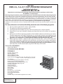
Ford
4.6/5.
2V
ExpeF-150/F-24
5
d
0
i
t
i
o
n
Supe
/N
Insta rcharge aviga
llatio
t
n Insr System or
tr
50 St
ate
1997
-200
Smog
Lega 3 Model
Y
l per
CARBears
EO #D
-213-
uctio
ns
20
®
ENGINEERING, LLC
1650 PACIFIC AVENUE • CHANNEL ISLANDS, CA 93033-9901 • (805) 247-0226
FAX (805) 247-0669 • www.vortechsuperchargers.com • M-F 8:00 AM - 4:30 PM PST
P/N: 4FM020-010
© 2003 Vortech Engineering, LLC
All Rights Reserved. Intl. Copr. Secured
20OCT03 v3.1 4.6/5.4Exped/Nav(4FM v3.1)
FOREWORD
Proper installation of this supercharger kit requires general automotive mechanic
knowledge and experience. Please browse through each step of this instruction manual
prior to beginning the installation to determine if you should refer the job to a professional
installer/technician. Please call Vortech Engineering for installers in your area.
© 2003 VORTECH ENGINEERING, LLC
All rights reserved. No part of this publication may be reproduced, transmitted, transcribed,
or translated into another language in any form, by any means without written permission
of Vortech Engineering, LLC.
P/N: 4FM020-010
© 2003 Vortech Engineering, LLC
All Rights Reserved. Intl. Copr. Secured
20OCT03 v3.1 4.6/5.4Exped/Nav(4FM v3.1)
ii
Table Of Contents
FOREWORD ..................................................................................................................................... ii
TABLE OF CONTENTS .................................................................................................................... iii
DISCLAIMER .................................................................................................................................... iv
NOTICE ............................................................................................................................................. v
TOOL & SUPPLY REQUIREMENTS ................................................................................................ vi
PARTS LIST - 1997-2001 FORD 4.6L 2V F-150/F-250 .................................................................... vii
PARTS LIST - 1997-2001 FORD 5.4L 2V F-150/F-250 .................................................................... viii
1.
COMPONENT REMOVAL AND PREPARATION ................................................................. 1
2.
OIL FEED LINE INSTALLATION .......................................................................................... 2
3.
OIL DRAIN ........................................................................................................................... 3
4.
CRANKSHAFT PULLEY/SUPERCHARGER DRIVE PULLEY ............................................ 5
5.
FUEL PUMP ......................................................................................................................... 6
6.
FUEL PUMP RELAY ............................................................................................................ 7
7.
WIRE PREPARATION (4.6 Models only) ............................................................................. 8
8A.
MAIN MOUNTING PLATE ASSEMBLY AND MOUNTING (4.6 Models only) ...................... 9
8B.
MAIN MOUNTING BRACKET ASSEMBLY AND MOUNTING (5.4 Models only) ................ 10
9.
EGR CONTROL MOUNTING AND MAIN MOUNTING PLATE SUPPORT
(4.6 Models only) .................................................................................................................. 12
10.
FUEL MANAGEMENT UNIT (FMU) ..................................................................................... 13
11.
IDLER AIR CONTROL RESONATOR AND CRANKCASE VENT HOSE
REROUTING ........................................................................................................................ 14
12.
SUPERCHARGING MOUNTING ......................................................................................... 14
13.
MASS AIR FLOW SENSOR REMOVAL, MOUNTING AND ASSEMBLY ............................ 17
14.
AIR INLET/BYPASS ASSEMBLY ......................................................................................... 17
15.
DISCHARGE ........................................................................................................................ 19
16.
FINAL CHECK ...................................................................................................................... 19
iii
P/N: 4FM020-010
© 2003 Vortech Engineering, LLC
All Rights Reserved. Intl. Copr. Secured
20OCT03 v3.1 4.6/5.4Exped/Nav(4FM v3.1)
SUPERCHARGED F-150/F-250/EXPEDITION/NAVIGATOR
DISCLAIMER
Towing, racing performance driving, hard accelerations, and other heavy/severe duty driving
activities place extra demands on a vehicle’s transmission. If you use or plan to use your
supercharged ‘97 or later Ford F-150, F-250, Expedition under any of these special driving
circumstances, Vortech suggests that you evaluate the purchase of a transmission shift improver
product.* In simple terms, a transmission shift improver product is designed to improve the
performance and durability of your vehicle’s transmission.
Several companies make these shift improver products including TransGo Performance. Please
contact TransGo Performance or one of the other product companies directly should you wish to
obtain more information about their shift improver products.
TransGo Performance
2621 Merced Avenue
El Monte, CA 91733
(626) 443-4953 phone
(626) 443-1079 fax
NOTE: This listing is provided solely for informational purposes.
VORTECH has made no evaluation of the quality or functionality of these products and DOES NOT MAKE ANY RECOMMENDATION, ENDORSEMENT, NOR PROVIDE ANY WARRANTY ON ANY OF THESE SHIFT IMPROVER PRODUCTS.
* Only applies to vehicles equipped with automatic transmissions.
P/N: 4FM020-010
© 2003 Vortech Engineering, LLC
All Rights Reserved. Intl. Copr. Secured
20OCT03 v3.1 4.6/5.4Exped/Nav(4FM v3.1)
iv
IMPORTANT NOTES
1999-2003 Models
This kit requires ECM modification and the installation of a Vortech/Superchips ECM
Module. The ECM must be sent directly to Vortech by the installing customer (the charge
for this service with module installation has been included in the purchase price).
• Included in this kit is a prepaid next-day air shipping box and a credit tag for one (1)
Vortech/Superchips ECM Module.
• The modules are made specifically for each individual vehicle with respect to the
factory ECM calibration.
• Simply contact the Vortech Service Department at (805) 247-0226 to request a
Return Authorization Number (See ECM Module Credit Tag for more details).
- Mail to Vortech the enclosed "ECM Module Credit Tag" (send original tag - no
photocopies will be accepted) and ECM in the supplied box.
- Turnaround time will be 1-2 days (each application varies). Vortech will give an
estimate at the time of your order.
Your Vortech/Superchips ECM Module comes with a twelve (12) month limited
warranty from the original date of purchase of your supercharger system (see
Owner's Manual for details).
NOTE: Vortech Engineering is not responsible for engine or ECM damage due
to an improperly installed/mishandled ECM module or ECM.
This product is protected by state common law, copyright and/or patent. All legal rights
therein are reserved. The design, layout, dimensions, geometry, and engineering
features shown in this product are the exclusive property of Vortech Engineering, LLC.
This product may not be copied or duplicated in whole or part, abstractly or fundamentally,
intentionally or fortuitously, nor shall any design, dimension, or other information be
incorporated into any product or apparatus without prior written consent of Vortech
Engineering, LLC.
v
P/N: 4FM020-010
© 2003 Vortech Engineering, LLC
All Rights Reserved. Intl. Copr. Secured
20OCT03 v3.1 4.6/5.4Exped/Nav(4FM v3.1)
1997-2003
FORD 4.6L, 5.4L 2V F-150/F-250/EXPEDITION/NAVIGATOR
Installation Instructions
CARB EO #D-213-20
Congratulations on selecting the best performing and best backed automotive supercharger available today...
the VORTECH ® V-2 ® Supercharger!
Before beginning this installation, please read through this entire instruction booklet and the Street Supercharger System
Owner's Manual which includes the Limited Warranty Program and the Warranty Registration form and return envelope.
Vortech supercharger systems are performance improving devices. In most cases, increases in torque of 30-35% and
horsepower of 35%-45% can be expected with the boost levels specified by Vortech Engineering. This product is intended for
use on healthy, well maintained engines. Installation on a worn-out or damaged engine is not recommended and may result in
failure of the engine as well as the supercharger. Vortech Engineering is not responsible for engine damage.
Installation on new vehicles will not harm or adversely affect the break-in period so long as factory break-in procedures are
followed.
For best performance and continued durability, please take note of the following key points:
1.
2.
3.
4.
5.
6.
Use only premium grade fuel 91 octane or higher (R+M/2).
The engine must have stock compression ratio.
If the engine has been modified in any way, check with Vortech prior to using this product.
Always listen for any sign of detonation (pinging) and discontinue hard use (no boost) until problem is
resolved.
Perform an oil and filter change upon completion of this installation and prior to test driving your vehicle.
Thereafter, always use a high grade SF rated engine oil or a high quality synthetic, and change the oil and
filter every 3,000 miles or less. Never attempt to extend the oil change interval beyond 3,000 miles,
regardless of oil manufacturer's claims as potential damage to the supercharger may result.
Before beginning installation, replace all spark plugs that are older than 1 year or 20,000 miles with
original heat range plugs as specified by the manufacturer and reset timing to factory specifications
(follow the procedures indicated within the factory repair manual and/or as indicated on the factory
underhood emissions tag). Do not use platinum spark plugs unless they are original equipment. Change
spark plugs every 40,000 miles and spark plug wires at least every 60,000 miles.
TOOL & SUPPLY REQUIREMENTS
• Factory Repair Manual
• 3/8" Socket and Drive Set: SAE & Metric
• 1/2" Socket and Drive Set: SAE & Metric
• 3/8" Extension 3"
• 1/2" Extension 3"
• 3/8" NPT Tap and Handle
• Adjustable Wrench
• Harmonic Balancer Puller
• Harmonic Balancer Installer
• Open End Wrenches:5/16", 3/8", 7/16", 1/2", 9/16", 5/8", 11/16", 3/4"
10mm, 13-18mm, 18mm tappet (thin) wrench
• 3 lb. Hammer
• 1-1/16" Oil Sending Unit Socket (Snap-on #A119A)
• Center Punch and a 5/8" Tapered Punch
• Ford Springlock 3/8" Fuel Fitting Disconnect Tool
• 6 Quarts SH/CF Rated Quality Engine Oil
• Oil Filter and Wrench
• Flat #2 Screwdriver
• Phillips #2 Screwdriver
• Heavy Grease
• Silicone Sealer
• Drill Motor
• "R", 1/8", 3/16", 11/32" Drill Bits
• 3/16", 8mm Allen Wrenchs
• Wire Strippers and Crimpers
• Utility Knife
• 1/8" NPT Tap (for 4WD models equipped with oil coolers)
P/N: 4FM020-010
© 2003 Vortech Engineering, LLC
All Rights Reserved. Intl. Copr. Secured
20OCT03 v3.1 4.6/5.4Exped/Nav(4FM v3.1)
vi
1997-2001 Ford 4.6L 2V F-150/F-250/Expedition/Navigator
Part No. 4FM218-010S/018S
®
PARTS LIST
ENGINEERING, LLC
IMPORTANT: Before beginning installation, verify that all parts are included in the kit. Report any shortages or damaged parts immediately.
Part Number
Description
Quantity
Part Number
Description
Quantity
2E228-160
2E128-230
2A036-361
7U100-070
2A040-011
7B375-125
7K375-040
SUPERCHARGER ASSEMBLY
V-2 Supercharger
3.60 Supercharger Drive Pulley
3/16" x 3/16" x 7/8" Key
Pulley Retainer
3/8-24 x 1-1/4" HXHD Bolt
3/8" AN960 Flat Washer
1
1
1
1
1
1
1
4FM111-034
4FM011-033
7A375-251
7C100-085
7K437-001
8C080-020
7K312-001
4FM010-130
7A375-100
7F375-017
7K375-040
7R003-008
5W018-010
5W001-007
7C080-085
MAIN MOUNTING BRACKET ASSEMBLY
Mounting Plate Assembly
3/8-16 x 2-1/2” Flat SHCS
10mm x 1.50 x 85mm HXHD Bolts
7/16" AN Washers
8mm x 1.25 x 20mm HXHD Bolt
5/16" AN Washer
Bracket Support Strut
3/8-16 x 1" HXHD Bolt
3/8-16 Nylock Nut
3/8" AN960 Flat Washer
1/2" Adel Clamp
6" 18 Ga. Std. Red Wire
3/16" x 6" Heat shrink Tube
8mm Shoulder Bolts
1
1
5
3
3
1
1
1
1
1
1
1
1
1
4
8F203-265
5W001-001
5W001-011
7E010-050
7P312-003
7R004-003
7U100-044
7U100-055
7U031-018
8F101-200
5W001-014
5W001-015
5W001-010
7U030-050
8F001-002
7R003-024
7R001-008
7E010-075
7P500-004
FUEL PUMP ASSEMBLY
Wire Tap
16-14 Ga. Eyelets
#12 x 1/2” Sheet Metal Screw
5/16” Female Fuel Connector
14.5 Stepless Clamps
4” Tie Wraps
6” Tie Wraps
5/16” x 11” High Pressure Fuel Hose
T-Rex Wiring Assembly
Fuse Holder
20A Blade Type Fuse
16-14 Ga Female Slides
12mm x 16” Fuel Hose
155 Inline Fuel Pump
1-1/2" Adel Clamp
#8 Hose Clamps
#12 x 3/4" Sheet Metal HXHD Bolt
1/2" Fuel Fitting Adapter
1
1
2
1
1
2
3
4
1
1
1
1
3
1
1
1
2
1
1
4FM110-040
4FM010-040
7C010-150
7F010-024
7J010-001
7A250-075
7F250-021
7J250-001
4FM010-030
7C010-050
COIL/EGR/POWER STEERING ASSEMBLY
Coil Mounting Bracket
10-24 x 1-1/2" SH Bolts
10-24 Nylock Nuts
#10 Flat Washers
1/4-20 x 3/4” SH Cap Screws
1/4-20 Nylock Nuts
1/4" SAE Washers
EGR Bracket
10-24 x 1/2” SH Cap Screws
1
1
4
8
12
4
4
4
1
4
4FM111-032
4FM011-032
2A046-725
7J012-092
7C012-020
7C012-022
4FA016-150
4GF016-160
4FK116-021
7C100-085
7K437-001
2A017-021
4FM016-011
7C080-026
7K312-001
7C120-065
7J438-071
4FM016-012
SUPERCHARGER DRIVE ASSEMBLY
Belt Tensioner
Belt
12mm Flat Washers
12mm x 1.75 X 20mm Bolts
12mm x 1.75 X 20mm Thin Head Bolt
Smooth Pulley Tensioners
Ribbed Idler Pulley
Idler Pulley Assembly
10mm x 1.50 x 85mm HXHD Bolt
7/16" AN Washer
Spacer
Balancer
8mm x 1.25 x 25mm SH Bolts
5/16" AN Washers
12mm x 1.5 x 65mm HXHD Bolt
7/16" USS Washer
Crank Pulley
1
1
1
3
5
1
2
1
1
1
1
1
1
3
3
1
1
1
4FM112-010
4FM010-050
8H040-045
7R002-056
7S350-200
7U035-000
7U100-052
7U038-000
7P500-026
7P375-052
4FA012-012
4FA012-013
7A250-075
7F250-021
7J250-001
7U100-055
7A312-150
7J312-001
7J312-000
7F312-017
7U030-065
7U133-024
7P750-102
7R002-052
AIR INLET ASSEMBLY
MAF Bracket Assembly
3-3/4" Flanged Air Filter
#56 Hose Clamps
3-1/2” x 2" Sleeves
3-1/2” x 15" Flex Hose
7/16” Rubber Grommet
3/4” x 24” Heater Hose
1/2" NPT x 3/4” -90° Hose Barb
3/8" NPT x 5/8" 90° Hose Barb
90° Intake Elbow
90° Intake Elbow w/Boss
1/4-20 x 3/4” SH Cap Screws
1/4-20 Nylock Nuts
1/4” SAE Washers
6” Tie Wraps
5/16-18 x 1-1/2" HXHD Cap Screws
5/16" Fender Washers
5/16' SAE Flat Washers
5/16-18 Nylock Nuts
3/4" x 90° Hose
5/8" Molded Elbow Hose
3/4" NPT x 1" 90° Hose Fitting
#52 Hose Clamps
1
1
1
4
2
1
1
1
1
1
1
1
4
4
4
6
2
2
2
2
1
1
1
2
4FM238-068
6Z110-114
4FA145-010
4FA145-020
7U030-046
7P156-082
7U100-055
FMU (with lines)
8:1 Fuel Management Unit
Male Fuel Line
Female Fuel Line
5/32” x 18” Vacuum Line
5/32” Tee
6” Tie Wraps
1
1
1
1
1
1
4
4FM112-020
4FM012-020
7S300-200
7S275-200
7R002-044
7R002-048
7R002-016
8D001-001
7U034-016
7U034-016
7U030-046
7P156-082
7S275-300
7P375-106
DISCHARGE ASSEMBLY
Discharge Tube
3” x 2” Sleeve
2-3/4” x 2” Sleeve
#44 Hose Clamps
#48 Hose Clamps
#16 Hose Clamps
Bypass Valve
1” x 7” Heater Hose
1” x 5” Heater Hose
5/32” x 12” Vacuum Line
5/32” Tee
2-3/4" x 3" Sleeve
PCV Valve
1
1
1
1
2
2
4
1
1
1
1
1
1
1
4FM130-036
7U030-036
7R001-008
7P375-042
4FH100-010
OIL DRAIN ASSEMBLY
1/2” x 32” Oil Drain Hose
#8 Stainless Hose Clamps
Male Connector
Oil Drain Tube Nut Assy.
1
1
2
1
1
4FM130-026
7U030-026
7P525-067
7P250-066
7P125-026
7U100-055
7P250-082
7P250-122
7P250-123
7P250-034
7U030-026
7P125-103
OIL FEED ASSEMBLY
1/4" x 36” Oil Feed Hose
.525 Crimp Ferrules
-4 Swivel x 1/4” Hose Barb Fittings
1/8" NPT x #4 -90° Fitting
6” Tie Wraps
1/4" NPT x -4 -90° Fitting
1/4" Pipe Thread Tee
1/4" NPT x 1-1/2" Nipple
1/4 NPT Strt. Tee
1/4" x 62" Oil Feed Hose
1/8" NPT x 45" #4 Ftg.
1
1
2
2
1
4
1
1
1
1
1
1
vii
P/N: 4FM020-010
© 2003 Vortech Engineering, LLC
All Rights Reserved. Intl. Copr. Secured
20OCT03 v3.1 4.6/5.4Exped/Nav(4FM v3.1)
1997-2001 Ford 5.4L 2V F-150/F-250/Expedition/Navigator
Part No. 4FM218-020/028S
®
PARTS LIST
ENGINEERING, LLC
IMPORTANT: Before beginning installation, verify that all parts are included in the kit. Report any shortages or damaged parts immediately.
Part Number
Description
Quantity
Part Number
Description
Quantity
2E228-170
2E128-220
2A038-333
7U100-070
2A040-011
7B375-125
7K375-040
SUPERCHARGER ASSEMBLY
V-2 Supercharger
3.33 8 Rib Pulley
3/16" x 3/16" x 7/8" Key
Pulley Retainer
3/8-24 x 1-1/4" HXHD Bolt
3/8" AN960 Flat Washer
1
1
1
1
1
1
1
4FM111-054
4FA016-170
4FA016-171
4FM010-140
4FM010-150
4FM011-021
4FM016-031
4FM017-010
4FM017-020
7A250-075
7A250-100
7A375-175
7A375-250
7A437-150
7C010-080
7C060-016
7F250-021
7J006-093
7J250-001
7J438-091
7K375-040
7J010-002
5W001-012
5W001-006
7C140-030
5W018-070
5W018-030
7P375-050
7R001-004
7U032-016
4FM010-160
MAIN MOUNTING BRACKET ASSEMBLY
Idler Smooth
Dust Shields
Bracket Support
Bracket Support #2 5.4
Mounting Bracket Mach.
Idlers Grooved
Spacer Short Bracket Support #2
Spacer Long Bracket Support #2
1/4-20 x 3/4" S.H.C.S.
1/4-20 x 1" Flat Allen
3/8-16 x 1.75" Hex Head
3/8-16 x 2.5" Hex Head
7/16-14 x 1.5" Bolt Hex Head
10mm x 1.5 x 80mm S.H.C.S.
M6 x 1.00 x 16 HXHD Bolt
1/4-20 Nylock Nut
6mm Washer
1/4 SAE Washer Plated
9/16 SAE Washers Plated
3/8" AN 960 Flat Washer
10mm Washer
Solderless Connector
3/8" Heat Shrink Tubing 12"
14mm x 2.0 x 30mm HXHD
18 GA Wire Green 12"
18 GA Wire Grey 12"
3/8 Hose Mender
#4 Hose Clamp
3/8" Hose Hi-Pressure 18"
Power Steering Bracket
1
1
2
1
1
1
2
1
1
6
1
2
3
3
3
1
3
1
1
2
5
3
4
1
1
1
1
1
4
1
1
4FM112-040
4FM010-050
8H040-045
7R002-056
7S350-200
7U035-000
7U100-052
7U038-000
7P500-026
7P375-052
4FA012-012
4FA012-013
7A250-075
7F250-021
7J250-001
7U100-055
7A312-150
7J312-001
7J312-000
7F312-017
7U030-065
7U133-024
7P750-102
7R002-052
AIR INLET ASSEMBLY
MAF Bracket Assembly
3-3/4" Flanged Air Filter
#56 Hose Clamps
3-1/2” x 2" Sleeves
3-1/2” x 15" Flex Hose
7/16” Rubber Grommet
3/4” x 24” Heater Hose
1/2" NPT x 3/4” -90° Hose Barb
3/8" NPT x 5/8” -90° Hose Barb
90° Intake Elbow
90° Intake Elbow w/Boss
1/4-20 x 3/4” SH Cap Screws
1/4-20 Nylock Nuts
1/4” SAE Washers
6” Tie Wraps
5/16-18 x 1-1/2" HXHD Cap Screws
5/16" Fender Washers
5/16' SAE Flat Washers
5/16-18 Nylock Nuts
3/4" x 90° Hose
5/8" Molded Elbow Hose
3/4" NPT x 1" 90° Hose Fitting
#52 Hose Clamps
1
1
1
4
2
1
1
1
1
1
1
1
4
4
4
6
2
2
2
2
1
1
1
2
4FM112-030
4FM012-030
7P156-082
7R002-016
7R002-044
7R002-048
7S275-200
7S300-200
7U030-046
7U034-016
7U034-016
8D001-001
7P375-106
5.4 DISCHARGE ASSEMBLY
Discharge Tube 5.4 (Only)
5/32” TEE
#16 Hose Clamps
#44 Hose Clamps
#48 Hose Clamps
2-3/4” x 2” Sleeve
3” x 2” Sleeve
5/32” x 12” Vacuum Line
1" x 9" Heater Hose
1" x 2.5" Heater Hose
Bypass Valve
PCV Valve
1
1
1
4
2
2
1
1
1
1
1
1
1
4FM111-062
2A048-802
4FA016-170
4FA016-171
4FM011-052
4FM016-011
4FM016-041
7A375-324
7C010-045
7C080-026
7C120-065
7J438-071
7K312-001
7K375-040
SUPERCHARGER DRIVE ASSEMBLY
Belt 8 rib x 80.14"
Idler Smooth
Dust Shields
Spring Tensioner Long Ford
Balancer
Crank Pulley, 8 Rib
3/8-16 x 3.25" HXHD Bolt
10mm x 1.5 x 45mm Hex Head
8mm x 1.25 x 25mm SH Bolts
12mm x 1.5 x 65mm HXHD Bolt
7/16" USS Washer
5/16" AN Washers
3/8" AN 960 Flat Washer
1
1
1
1
1
1
1
1
1
3
1
1
3
1
4FM130-026
7U030-026
7P525-067
7P250-066
7P125-026
7U100-055
7P250-082
7P250-122
7P250-123
7U030-026
7P250-034
7P125-103
OIL FEED ASSEMBLY
1/4" x 36” Oil Feed Hose
.525 Crimp Ferrules
-4 Swivel x 1/4” Hose Barb Fittings
1/8" NPT x #4 -90° Fitting
6” Tie Wraps
1/4" NPT x -4 -90° Fitting
1/4" Pipe Thread TEE
1/4" NPT x 1-1/2" Nipple
1/4" x 62" Oil Feed Hose
1/4" NPT Strt. TEE
1/8" NPT x 45" #4 Fitting
1
1
2
2
1
4
1
1
1
1
1
1
8F203-265
5W001-001
5W001-011
7E010-050
7P312-003
7R004-003
7U100-044
7U100-055
7U031-018
8F101-200
5W001-014
5W001-015
5W001-010
7U030-050
8F001-002
7R003-024
7R001-008
7E010-075
7P500-004
FUEL PUMP ASSEMBLY
Wire Tap
16-14 Ga. Eyelets
#12 x 1/2” Sheet Metal Screw
5/16” Female Fuel Connector
14.5 Stepless Clamps
4” Tie Wraps
6” Tie Wraps
5/16” x 11” High Pressure Fuel Hose
T-Rex Wiring Assembly
Fuse Holder
20A Blade Type Fuse
16-14 Ga Female Slides
12mm x 16” Fuel Hose
155 Inline Fuel Pump
1-1/2" Adel Clamp
#8 Hose Clamps
#12 x 3/4" Sheet Metal HXHD Bolt
1/2" Fuel Fitting Adapter
1
1
2
1
1
2
3
4
1
1
1
1
3
1
1
1
2
1
1
4FM130-036
7U030-036
7R001-008
7P375-042
4FH100-010
OIL DRAIN ASSEMBLY
1/2” x 32” Oil Drain Hose
#8 Stainless Hose Clamps
Male Connector
Oil Drain Tube Nut Assy.
1
1
2
1
1
MAF CLAMP ASSEMBLY
1
4FM238-068
6Z110-114
4FA145-010
4FA145-020
7U030-046
7P156-082
7U100-055
FMU (with lines)
8:1 Fuel Management Unit
Male Fuel Line
Female Fuel Line
5/32” x 18” Vacuum Line
5/32” TEE
6” Tie Wraps
1
1
1
1
1
1
4
P/N: 4FM020-010
© 2003 Vortech Engineering, LLC
All Rights Reserved. Intl. Copr. Secured
20OCT03 v3.1 4.6/5.4Exped/Nav(4FM v3.1)
5A101-016
viii
1.
COMPONENT REMOVAL AND PREPARATION
A.
Disconnect the negative battery cable.
NOTE: 1999-2003 Models Only
1. Remove the passenger side front kick panel from
the interior of the vehicle. Remove the sound
deadening material (if any) that is covering the
ECM. Remove the plastic ECM hold-down
bracket.
2. From the engine side of the firewall (in the engine compartment), use a 10mm socket or
wrench and remove the harness and plug from
the ECM (as you loosen the bolt, the connector
will slowly release). Remove the ECM from the
vehicle.
3. Contact the Vortech Service Department for a
Return Authorization Number. Send both ECM
and supplied credit tag to Vortech using the enclosed shipping box.
B.
C.
Remove the throttle body/throttle linkage cover.
Detach the crankcase ventilation tube from the driver's
side valve cover and the air inlet.
D. Remove the idle air control resonator and air filter
cover.
E. Unplug the intake air temperature sensor (IAT) and
the mass air flow (MAF) sensor.
F. Detach all remaining components of the air inlet assembly and set aside.
* G. From the left side coil, unplug the radio ignition interference capacitor, remove the spark plug wires and
coil plug.
* H. Remove the cam trigger plug, unbolt the coil and remove the coil bracket.
I.
Separate
the EGR pressure transducer and the EGR
*
vacuum regulator solenoid from their bracket, unbolt
the bracket from the intake manifold and set aside.
J. Unbolt the power steering fluid reservoir from its
bracket. Separate the throttle cables from the retainer
bracket. Remove the main bracket from the waterneck
and the head and set aside.
K. Remove the plastic wire harness holder mounted on
the upper row of valve cover bolts on the driver's side.
L. Remove the accessory drive belt and set aside.
*4.6 MODELS ONLY
1
P/N: 4FM020-010
© 2003 Vortech Engineering, LLC
All Rights Reserved. Intl. Copr. Secured
20OCT03 v3.1 4.6/5.4Exped/Nav(4FM v3.1)
2.
OIL FEED LINE INSTALLATION
A.
B.
Unplug the connector on the oil pressure sending unit.
Remove the sending unit from the engine block. (The
unit is located on the left front side of the engine, just
above the oil pan.)
Thread the supplied 1/4" NPT fittings into the block as
shown. Reinstall the sending unit and connector.
2WD only
ENGINE
BLOCK
1/4” NPT
nipple
1/4” NPT
tee
4WD applications only (without oil cooler)
1/4” NPT x -4
flare
• Remove the remote oil filter hose assembly from the two
studs on the engine block. Disconnect the factory oil
sending unit connector and remove the sending unit.
• Following the graphic for 4WD applications, attach t h e
supplied 1/4 NPT straight TEE and 90° fitting into the
hole previously occupied by the oil sending unit. Attach
the oil sending unit into the remaining 1/4 NPT opening
in the TEE.
• Reconnect the oil filter hose assembly to the original
location on the engine block. Make sure the gasket is in
its proper location. Replace gasket if needed.
• Reattached connector to sending unit.
4WD applications only
(equipped with factory oil cooler)
Factory
sending unit
VIEW FROM FRONT
Fig. 2-a
4WD Only (without oil cooler)
• Remove the oil filter from the filter base located behind
the front bumper of the vehicle.
• Remove the oil filter base mounting bracket from the
frame. Remove the oil filter mounting base from the
bracket.
• Mark the base in the same location as shown in the photo.
Center punch the previously marke spot on the base (make
sure that the spot is marked on the center port of the
filter base). Drill with an 'R' size drill bit and thread with a
1/8" NPT tap.
• Thoroughly clean and blow dry the filter base taking care
to remove any chips or burrs.
Remote oil filter
hole assembly
Factory oil
sending unit
location (remove)
DRIVER’S
SIDE VIEW
Fig. 2-b
1/4” NPT x -4
flare
Oil feed to
supercharger
1/4” NPT
street tee
ENGINE
BLOCK
Relocated sending unit
TOP VIEW
Fig. 2-c
P/N: 4FM020-010
© 2003 Vortech Engineering, LLC
All Rights Reserved. Intl. Copr. Secured
20OCT03 v3.1 4.6/5.4Exped/Nav(4FM v3.1)
2
Remote oil
filter hose
assembly
2.
OIL FEED LINE INSTALLATION, cont'd.
• Using a light amount of oil on the threads for lubrication,
thread the 1/8" NPT x 45° x #4 fitting into the threaded
hole. Teflon tape, paste or other sealant is not
recommended as it might loosen and cause blockage of
the oil feed orifice, resulting in supercharger failure. Rotate
the fitting so that when it is tight, it will face the front of
the vehicle.
• Reassemble the oil filter base and bracket and secure
onto the vehicle. Reinstall oil filter.
4WD (equipped with factory oil cooler)
WARNING: Use engine oil on the pipe threads, Teflon
tape, or sealant is not recommended as it
might loosen and cause blockage of the oil
feed orifice resulting in supercharger failure.
Center Punch location (x)
Fig. 2-d
C. Temporarily cap off the flare fitting to prevent dirt from
entering the oil feed, it will be connected to the
supercharger at a later time.
3.
OIL DRAIN
A.
To provide a proper oil drain for the supercharger it is
necessary to make a hole in the oil pan. The best way
to provide this hole is to punch the hole rather than
drill it.
B. Locate the appropriate area for the through hole as
shown in the following illustration, remove the paint
around the hole area. (Transmission cooler lines may
need slight bending to achieve oil drain tube and fitting clearance).
C. Use a small center punch to perforate the pan, expand the hole to approximately 9/16” diameter. Most
punches are made from a hexagonal material and may
be placed in a socket to make this task easier.
D. Tap the hole with a 3/8” NPT pipe tap
approximately 1/4” deep. Pack the
pipe tap flutes with heavy grease to
hold the chips and use a small magnet to check for any stray chips.
5/8"
1-7/8"
OIL PAN
FRONT VIEW
Fig. 3-a
3
P/N: 4FM020-010
© 2003 Vortech Engineering, LLC
All Rights Reserved. Intl. Copr. Secured
20OCT03 v3.1 4.6/5.4Exped/Nav(4FM v3.1)
3.
OIL DRAIN, cont'd.
NOTE: This method of rolling over the lip of the
hole and tapping works very well if carefully done and should cause no problem.
E.
Thoroughly clean the threaded area. Apply a small
amount of silicone sealer to the new threads. Apply
more sealer to the 3/8" NPT x 1/2" inverted flare fitting
and secure in hole. Make sure a seal is formed all
around the fitting.
F. Thread the tube nut and 1/2" x 90° aluminum tube
into the inverted flare fitting by hand. Do not tighten
until after the supercharger drain hose has been connected.
G. Drain the engine oil and change the oil filter.
H. Temporarily cap off the oil drain fitting to keep out
debris until the drain hose is attached to the supercharger at a later time.
I. Refill engine with 5W/30 synthetic or conventional SH/
CF rated motor oil.
FRONT VIEW
Fig. 3-b
DRAIN HOSE
FROM
SUPERCHARGER
CRANK
PULLEY
OIL
DRAIN
TUBE
OIL PAN
VIEW FROM PASSENGER SIDE
Fig. 3-c
P/N: 4FM020-010
© 2003 Vortech Engineering, LLC
All Rights Reserved. Intl. Copr. Secured
20OCT03 v3.1 4.6/5.4Exped/Nav(4FM v3.1)
4
4. CRANKSHAFT PULLEY/SUPERCHARGER DRIVE PULLEY
NOTE: This process can be done with the fan
shroud and radiator in place providing your
balancer puller is equipped with a 5” or
shorter forcing screw. Removing the fan
shroud and the radiator will allow easier
access to the crank pulley and the front of
the engine.
A.
B.
Remove the rubber inspection plug on the left rear of
the block to make the flexplate accessible. Using an
18mm socket and a 1/2” drive ratchet, rotate the engine until a flexplate nut is visible. Place a 14mm deep
socket and extension on the flexplate nut and rotate
the engine counterclockwise until the socket engages
with the top of the access hole. This will block the
movement of the crankshaft allowing the bolt to be
loosened. This operation may require the assistance
of another person. Remove the center balancer bolt.
Install the harmonic balancer puller. Evenly start three
puller bolts (not supplied - 8mm x 1.25 on the 4.6L
and 10mm x 1.50 on the 5.4L). Engage the forcing
screw against the pivot and check alignment.
Fig. 4-a
NOTE: When using the harmonic balancer
puller pay special attention to alignment
of the forcing screw and pivot, improper
alignment can result in damage to the
crankshaft.
C.
After ensuring the puller is properly aligned on the
face of the crank, slowly tighten the forcing screw until
the harmonic balancer has been removed.
NOTE: The factory uses a small amount of silicone to seal the crankshaft keyway.
Thoroughly clean the silicone residue
off of the crankshaft prior to installing
the Vortech harmonic balancer.
D. With a dab of silicone on the keyway of the new harmonic balancer, guide it on the crankshaft and feel for
alignment of the woodruff key and the harmonic balancer keyway. After the harmonic balancer has been
aligned on the crankshaft, use your harmonic balancer
installation tool to install the new harmonic balancer.
Slowly tighten until the harmonic balancer is seated
on the crankshaft.
NOTE: The use of blue Loctite is recommended for all harmonic balancer and
crank pulley bolts.
5
P/N: 4FM020-010
© 2003 Vortech Engineering, LLC
All Rights Reserved. Intl. Copr. Secured
20OCT03 v3.1 4.6/5.4Exped/Nav(4FM v3.1)
4.
CRANKSHAFT PULLEY/SUPERCHARGER DRIVE PULLEY, cont'd.
E.
F.
5.
Remove the installation tool and place the supercharger drive
pulley on the front of the harmonic balancer. Feeling for alignment, start the 12mm x 1.50 x 65mm center bolt with thick
factory washer and rotate the supercharger drive pulley until
the three bolt holes are aligned. Start the three 8mm x 1.25 x
25mm cap screws with washers, tighten all evenly beginning
with the center bolt (some applications may need two washers under each 8mm bolt head for thru-bolt clearance to the
engine front cover. Inspect behind balancer when tightening).
Torque the 12mm bolt to 80 ft/lbs and the 8mm bolts to 25 ft/
lbs.
Reinstall the inspection cover.
FUEL PUMP
A.
B.
C.
Release any pressure from the fuel tank by momentarily loosening the filler cap.
Disconnect the line from the tank to the fuel filter by carefully
removing the white retaining clip or by using a 3/8” springlock
disconnect tool, if equipped.
Connect the fuel pump inlet adapter fitting to the existing fuel
line coming from the fuel tank. Attach the supplied 1/2" inlet
hose to the adapter and pump inlet.
NOTE: Due to the various fuel tank configurations and
frame rail lengths it will be necessary to find a
good mounting location near the fuel filter. Do
NOT mount the fuel pump close to exhaust heat
or to the bottom of the cab. The inside or the
outside of the frame rail will work well. Prior to
securing the fuel pump ensure the fuel lines will
not be kinked or pinched and are protected from
sharp edges.
D. Connect the fuel pump outlet to the filter inlet.
E. With the fuel pump in a position that
allows the lines to be routed loosely,
secure the fuel pump with the #12
hex screw.
F. Secure the pump inlet hose using
the supplied #8 clamps. Trim hose
length if necessary. Ensure that NO
kinks or sharp bends are allowed
on pump inlet hose or failure may
result.
G. Attach the negative pump terminal
to a clean ground. Scrape the vehicle undercoat down to bare metal.
EXISTING FEED LINE
FROM TANK
ADAPTER
FITTING
1/2” FUEL LINE
5/16” HOSE
STOCK
FUEL
FILTER
(-) GROUND BLACK WIRE
CONNECT TO
(+) RELAY
TERMINAL (87)
Fig. 5-a
P/N: 4FM020-010
© 2003 Vortech Engineering, LLC
All Rights Reserved. Intl. Copr. Secured
20OCT03 v3.1 4.6/5.4Exped/Nav(4FM v3.1)
6
6.
FUEL PUMP RELAY
A.
Remove the power distribution box from its mounting bracket. Remove the bottom cover and the side
panel exposing the main power lugs, the bottom of
the fuses and relays.
B. Looking at the underside of the power distribution box,
locate the fuel pump relay (should be labeled #4).
Directly beneath the fuel pump relay, locate the green
wire with yellow stripe.
C. With the help of an assistant and a test light, check
the green/yellow wire for key-on power, this wire
should show power for approximately two to four seconds with the key in the accessory on position.
D. From relay terminal #85 route the yellow wire into the
bottom of the power distribution box. Tap into the
green/yellow wire with the provided wire tap. Double
check the wire with a test light to ensure a good connection has been made.
E. From terminal #30 route the heavy red wire to one of
the main power lugs at the side of the power distribution box. With the supplied male and female solderless
connectors, install the fuse holder and 20 amp fuse in
this wire and check with a test light to ensure a good
connection has been made. Close the bottom and side
covers and return the power distribution box to its
original position.
F. Mark and drill a 1/8” hole above the power distribution box on the driver's side inner fenderwell, secure
with the #12 x 3/4" sheet metal screw and washer
provided.
G. Connect the short black wire from relay terminal #86
to a secure ground free from paint.
H. From terminal #87, route and connect the long red
wire to the (+) side of the fuel pump. Secure with provided tie wraps.
7
Fig. 6-a
(+) T-REX FUEL PUMP
(LONGEST RED WIRE)
86
85
87
87A
GROUND
TO #4 RELAY GREEN WIRE WITH
YELLOW STRIPE
12 VOLT (+)
30
RELAY
Fig. 6-b
NOTE: Double check that all wires are connected to their proper relay lug.
P/N: 4FM020-010
© 2003 Vortech Engineering, LLC
All Rights Reserved. Intl. Copr. Secured
20OCT03 v3.1 4.6/5.4Exped/Nav(4FM v3.1)
7.
WIRE PREPARATION (4.6 models only)
A.
To accommodate the installation of the supercharger
and the relocation of the coil, it will be necessary to
modify the coil and cam trigger loom, extend the radio ignition interference wire and relocate the spark
plug wire clips.
B. Remove the 90° plastic wire support from the cam
sensor plug, this will allow the wire to be routed tightly
against the face of the main mounting plate at a later
time.
C. Carefully remove approximately 6” of wire wrap from
the loom containing the coil, cam position sensor and
the radio ignition interference capacitor wire. Separate the wires and rewrap them individually using black
electrical tape and the provided wire wrap.
D. Cut the radio ignition interference wire approximately
4” from the plug and strip approximately 3/4” of insulation off of the wire. Slip the two 2” pieces of
shrink tube over the exposed wire ends. Solder in the
6” length of red 16 gauge wire.
E. To allow the relocation of the coil, it is necessary to
remove all spark plug wire retaining clips between
the alternator and coil as they will be reinstalled after
the coil has been moved to its new location.
COIL PACK
CONNECTOR
IGNITION
CAPACITOR
CAM TRIGGER
CONNECTOR
REMOVE PLASTIC
90° WIRE SUPPORT
EXTEND WITH 6”
WIRE, SOLDER
AND SHRINK TUBE
UNWRAP “Y” BEND
APPROXIMATELY 6”
Fig. 7-a
P/N: 4FM020-010
© 2003 Vortech Engineering, LLC
All Rights Reserved. Intl. Copr. Secured
20OCT03 v3.1 4.6/5.4Exped/Nav(4FM v3.1)
8
8A. MAIN MOUNTING PLATE ASSEMBLY AND MOUNTING (4.6L models only)
A.
Attach the supplied power steering reservoir/coil
bracket to the main mounting plate using the 1/4-20
x 3/4” bolts, nuts and washers (see photo).
B. Using the supplied 10-24 x 2” bolts and washers, secure the coil and the radio ignition interference capacitor to the power steering reservoir/coil bracket.
C. To prepare the mounting location for the main mounting plate, remove the three factory stud/bolts previously used to hold the factory coil bracket to the engine front cover.
D. Remove the front cover bolt located near the lower
driver's side of the alternator mounting flange. In this
location, install the supplied 2.25” idler pulley and idler
spacer using the 10mm x 1.50 x 85mm bolt and
washer. Torque to 40 in/lbs.
NOTE: In a limited number of 4.6L engines,
the main bracket holes and single idler
pulley hole are 8mm instead of 10mm.
Four 8mm shoulder bolts have been
supplied for these models.
E.
Fig. 8A-a
Reinstall the accessory belt.
NOTE: The use of blue Loctite is recommended
for all idler bolts.
2.25" IDLER PULLEY
F.
With the main mounting plate positioned on the front
cover, start the supplied 8mm-1.25 x 25mm bolt and
the three 10mm -1.50 x 85mm bolts with washers
into the front cover. Torque all bolts evenly.
G. Install the large smooth idler on the inner most idler
stand and the ribbed idler on the outer stand of the
Vortech mounting plate. Secure both with the 12mm
- 1.75 x 20mm bolts and dust shields provided. Torque
to 45 ft/lbs.
H. Install the cam position sensor plug and secure the
wire to the face of the main mounting plate with the
provided adel clamp. Use the lower coil bracket bolt
to secure clamp.
Fig. 8A-b
SMOOTH IDLER
RIBBED IDLER
Fig. 8A-c
9
P/N: 4FM020-010
© 2003 Vortech Engineering, LLC
All Rights Reserved. Intl. Copr. Secured
20OCT03 v3.1 4.6/5.4Exped/Nav(4FM v3.1)
8A. MAIN MOUNTING PLATE ASSEMBLY AND MOUNTING (4.6L models only) cont'd.
I.
J.
K.
Move the power steering reservoir into the appropriate location on the new power steering reservoir/coil
mounting bracket and secure with the provided 1/4"
hardware.
Secure the power steering reservoir lines away from
the steering shaft with the tie wraps provided.
Reattach the plug wires to the coil and secure with
the previously removed clips.
Fig. 8A-d
8B. MAIN MOUNTING BRACKET ASSEMBLY AND MOUNTING (5.4L models only)
A.
B.
To prepare the mounting location for the main mounting plate, remove the three 10mm factory stud/bolts
located on the driver side engine front cover.
Reinstall the accessory belt.
NOTE: The use of blue Loctite is recommended for all idler bolts.
C.
Cut and extend the cam sensor wires using the supplied 18GA wires and solderless connectors. Using
tie wraps secure the cam sensor wire as shown in the
photo.
D. Install the large support bracket onto the engine block
using the 14mm x 2.0 x 35mm bolts, washers, and
spacers. NOTE: The most forward mounting boss
should use the 14mm x 2.0 x 30mm and the smaller
of the two spacers. (Do not tighten the bolts until the
upper part of the support bracket has been mounted.)
E. With the main mounting bracket positioned on the
front cover, (ensure that the cam sensor wire is not
being pinched by the mounting bracket) start the three
supplied 10mm x 1.5 x 80mm bolts with washers.
Torque all bolts evenly.
F. Secure the upper portion of the bracket to the previously installed support bracket using the supplied 1/4"
hardware.
G. Using the supplied 7/16-14 x 1.5" bolts and dust
shields, secure the three (3) idlers to the main mounting bracket in the configuration shown on page 15.
Fig. 8B-a
Fig. 8B-b
P/N: 4FM020-010
© 2003 Vortech Engineering, LLC
All Rights Reserved. Intl. Copr. Secured
20OCT03 v3.1 4.6/5.4Exped/Nav(4FM v3.1)
10
8B. MAIN MOUNTING BRACKET ASSEMBLY AND MOUNTING (5.4L models only), cont'd.
H. Install the supplied support strap between the back of
the main mounting bracket and the boss on top of the
thermostat housing. Secure both ends using the supplied 6mm bolt and washer and the 1/4-20 x 1" flat
allen bolt, washer and lock nut.
I. Attach the supplied power steering reservoir bracket
to the main mounting bracket using the 1/4-20 bolt
and washers (see photo).
J. Trim 4" off of the top end of the stock 5/8" supply hose
connecting the reservoir to the pump and reattach.
K. Extend the stock power steering return hose using
the supplied 3/8" line and hose mender. Secure with
the two supplied #4 hose clamps.
L. Mount the power steering reservoir onto the new
power steering reservoir bracket and attach with the
provided 1/4" hardware. Using tie wraps, secure the
power steering lines away from the steering shaft.
Fig. 8B-c
Fig. 8B-d
11
P/N: 4FM020-010
© 2003 Vortech Engineering, LLC
All Rights Reserved. Intl. Copr. Secured
20OCT03 v3.1 4.6/5.4Exped/Nav(4FM v3.1)
9.
EGR CONTROL MOUNTING AND MAIN MOUNTING PLATE SUPPORT
(4.6L models only)
A.
Using the #10-24 x 1/2” bolts, nuts and washers, remount the EGR controls onto the Vortech mounting
bracket.
B. Directly beneath the EGR bracket, locate the 6mm
bolt securing the fuel rail. Remove the bolt.
C. Install the supplied support strap between the intake
manifold and the main mounting plate. Secure both
ends using the factory 6mm fuel rail bolt and the supplied 3/8-16 x 1" hexhead bolt, nut and washer. Make
sure that the strap is not sandwiched in between the
fuel rail and the manifold. The support must be attached underneath the bolt, and on top of the rail tab.
Improper assembly may cause fuel leakage.
D. With the two factory 6mm bolts previously used to
mount the EGR controls, remount the new EGR assembly in the original location on the intake manifold
and secure. Reconnect all factory hoses and connectors.
Fig. 9-a
Fig. 9-b
10. FUEL MANAGEMENT UNIT (FMU)
A.
Using a spring lock disconnect tool, disconnect the
fuel return line at the fuel rail.
B. Connect the FMU inlet hose to the fuel rail. Route the
fuel line to the 90° brass fitting on the FMU.
C. Position FMU against the upper firewall directly under the plastic wire harness cover as shown. Mark
and drill two #30 holes on the firewall to mount the
FMU. Secure with the #8 sheet metal screws provided.
D. Connect the FMU outlet hose to the fuel line that returns to the tank. Route the fuel line to the straight
brass fitting on the FMU.
E. Secure the fuel lines away from abrasion and exhaust
P/N: 4FM020-010
© 2003 Vortech Engineering, LLC
All Rights Reserved. Intl. Copr. Secured
20OCT03 v3.1 4.6/5.4Exped/Nav(4FM v3.1)
12
Fig. 10-a
FACTORY VACUUM
CONNECTION
FUEL
MANAGEMENT
UNIT (FMU)
VACUUM LINE
FACTORY
SPRINGLOCK
CONNECTOR
FACTORY
REGULATOR
INLET
OUTLET
FUEL RETURN LINE
ENGINE
FACTORY
QUICKDISCONNECT
FITTING
FUEL FEED LINE
F.
heat with the provided tie wraps.
Tap into the factory fuel regulator vacuum line with the supplied
5/32" hose and TEE. Route the
new hose to the fitting on top of
the FMU (see drawing).
FILTER
T-REX
FUEL TANK
Fig. 10-b
10.1 FUEL MANAGEMENT UNIT
RECALIBRATION (2003 5.4L Only)
A.
Remove the six allen-head screws on top of the fuel
management unit (FMU). (See Fig. 7/1-a.)
WARNING:
Do not remove the four screws holding
the valve body. Once taken apart, the
vlave would have to be replacedl.
B.
Remove the diaphram and 7:1 disk (2.038' O.D.) and
ring from inside of the FMU.
C. Install the replacement 8:1 ring (with notched part
facing down) around the four screws inside the FMU.
(The 8:1 components are larger in diameter that their
7:1 counterparts.) Place the 8:1 disk (2.22' O.D.) inside the ring on top of the piston.
D. Install the new diaphram and carefully line up the holes
to the body.
E. Reinstall the FMU cover with the six allen-head screws.
Do not overtighten the screws. The correct torque is
24 in/lb (2 ft/lb.).
Fig. 10-c
13
P/N: 4FM020-010
© 2003 Vortech Engineering, LLC
All Rights Reserved. Intl. Copr. Secured
20OCT03 v3.1 4.6/5.4Exped/Nav(4FM v3.1)
11. IDLE AIR CONTROL RESONATOR AND CRANKCASE VENT HOSE REROUTING
* A. Attach the supplied 3/4” x 90° rubber elbow to the
B.
C.
idle control motor near the throttle body. (See Fig.
11-a.) Insert the factory idle control resonator into
the elbow and locate underneath the discharge tube.
Connect the supplied 3/4” x 28" hose to the idle control resonator and route the remaining end to the new
air inlet location. See step 14.
Remove the 90° rubber elbow from the factory valve
cover vent on the left side of the engine. Attach the
short leg of the supplied 5/8" x 90° x 24" hose to the
valve cover and route the long straight end over to
the brass fitting on the supercharger inlet elbow. Trim
hose length, if necessary. See step 14.
Fig. 11-a
*4.6L ONLY
12. SUPERCHARGER MOUNTING
A.
* B.
Attach the oil drain hose to the oil drain fitting on the
bottom of the supercharger and secure with the provided #8 hose clamp.
Guide the oil drain hose over the driver's side valve
cover while placing the supercharger in the appropriate location. (See Fig. 12-a.)
NOTE: The oil drain line must be routed in a
downward sloping fashion with no kinks
or restrictions.
C.
With the oil drain hose properly routed downward,
start the five 3/8-16 x 2-1/2” counter sink bolts and
tighten evenly.
5.4L ONLY - Once the oil drain hose has been properly routed downward, use the five 3/8-16 bolts and
washers, start and tighten evenly.
D. Route the oil drain hose around the side of the power
steering pump and to the oil drain fitting on the oil
pan.
NOTE: Do NOT use any type of sealant on the
oil feed fittings. It may become dislodged and clog the oil feed orifice,
causing premature failure of the supercharger.
E.
F.
Using a few drops of engine oil on the fitting threads,
install the 1/8” NPT x -4 x 90° fitting into the supercharger oil feed. Rotate the fitting toward the front of
the vehicle. Use a 1/2” wrench to hold the supercharger
oil feed while tightening the brass 90° fitting.
Two oil feed hoses have been supplied. The 36" long
hose is for use on the 2WD models that are not
equipped with an engine oil cooler. The 62" hose is
for use on 4WD oil cooler equipped models. Connect
the proper length oil feed line to the vehicle and secure both ends. Make sure that no dirt or debris enters the oil hose while routing to the feed fittings.
P/N: 4FM020-010
© 2003 Vortech Engineering, LLC
All Rights Reserved. Intl. Copr. Secured
20OCT03 v3.1 4.6/5.4Exped/Nav(4FM v3.1)
14
Fig. 12-a
*4.6L ONLY
12. SUPERCHARGER MOUNTING, cont'd.
G. Secure the oil feed line and oil drain line away from heat
and abrasion with the provided tie wraps.
*H. Mount the belt tensioner plate onto the face of the supercharger with the three 12mm x 1.75 x 20mm bolts and
washers. The thin head bolt must be installed nearest the
idler pulley pilot.
5.4L ONLY - Mount the automatic tensioner to the mounting bracket using the 3/8-16 x 3.25" bolt and washer.
I. Route the supplied supercharger drive belt around the supercharger crank pulley, the inner and outer idlers and to
the supercharger.
*J. Install the smooth tensioner pulley to the tensioner plate
pilot using the 12mm x 1.75 x 20mm bolt provided.
*K. With a 1/2” drive breaker bar and a 3” extension, rotate the
tensioner plate to tighten the belt. Tighten the three 12mm
fasteners. Use thin 18mm wrench to tighten the bolt head
nearest to the idler pulley.
*NOTE: The supercharger drive belt should have approximately 1" of deflection and will need to
be retightened between 250 to 400 miles.
5.4L ONLY - Using a 1/2" drive breaker bar, rotate the
tensioner clockwise and align belt. Release tensioner to
tighten belt.
M. Connect the oil drain hose down to the oil pan tube previously installed. Trim hose length if necessary and secure
with a #8 clamp. Make sure drain hose runs downhill continuously with no kinks or dips. Support fitting in oil pan
with a wrench while tightening the drain tube fitting. Make
sure the tube is angled up, but maintaining clearance from
the drive belt (see photo in step 3).
L.
VORTECH
TENSIONER
ALTERNATOR
VORTECH
SMOOTH
2.25 PULLEY
VORTECH
RIBBED
IDLER PULLEY
IDLER
WATER
PUMP
4.6L MODELS ONLY
VORTECH
SMOOTH
IDLER PULLEY
NOTE: SUPERCHARGER
BELT IS ON OUTSIDE
(FORWARD) OF ACCESSORY
BELT
TENSIONER
AIR
CONDITIONER
HARMONIC
BALANCER/
CRANK PULLEY
Fig. 12-c
15
POWER
STEERING
PUMP
*4.6L ONLY
P/N: 4FM020-010
© 2003 Vortech Engineering, LLC
All Rights Reserved. Intl. Copr. Secured
20OCT03 v3.1 4.6/5.4Exped/Nav(4FM v3.1)
12. SUPERCHARGER MOUNTING, cont'd.
5.4L MODELS ONLY
SPRING TENSIONER
RIBBED IDLERS
SMOOTH IDLER
HARMONIC
BALANCER/
CRANK PULLEY
Fig. 12-d
P/N: 4FM020-010
© 2003 Vortech Engineering, LLC
All Rights Reserved. Intl. Copr. Secured
20OCT03 v3.1 4.6/5.4Exped/Nav(4FM v3.1)
16
13. MASS AIR FLOW SENSOR REMOVAL, MOUNTING AND ASSEMBLY
A.
Separate the mass air flow sensor
from the air inlet canister.
B. Assemble the mass air sensor and
the mass air sensor mounting
bracket with the 1/4-20 x 3/4" bolts,
nuts and washers. Mount the air
filter to the bracket and secure the
#60 clamp.
C. Using the factory air inlet filter can- CRUISE
ister mounting location, secure the CONTROL
mass air bracket with the 5/16-18
x 1-1/2” bolts, nuts and washers;
use the large 5/16 fender washers
on the bottom of the factory rubber grommets.
D. Connect the 90° plastic elbow
MASS AIR
FLOW
equipped with the 3/4” barb 90°,
SENSOR
to the 3-1/2 silicone sleeve. Secure
with the #56 hose clamps.
E. 5.4 Models only - Wire/Install the
supplied MAF Voltage Limiter Assembly. Use the instruction sheet
supplied in the MAF Voltage Limiter Assembly.
INNER FENDERWELL
COOLANT
RESERVOIR
FRONT
TOP VIEW
Fig. 13-a
14. AIR INLET/BYPASS ASSEMBLY
A.
B.
Place the 3-1/2” silicone sleeve and the #56 hose
clamps onto the supercharger inlet. Install the 90°
plastic inlet elbow. Secure the #56 hose clamps. Insert the factory air temperature sensor into the rubber grommet located on the inlet elbow and attach
the connector.
Attach the supplied 1” x 5” hose 1" x 9" hose -4.6L,
5.4L and #16 hose clamp to the 1” plastic 90° fitting
installed on the inlet elbow. Secure clamp.
AIR TEMPERATURE
SENSOR
Fig. 14-a
17
P/N: 4FM020-010
© 2003 Vortech Engineering, LLC
All Rights Reserved. Intl. Copr. Secured
20OCT03 v3.1 4.6/5.4Exped/Nav(4FM v3.1)
14. AIR INLET/BYPASS ASSEMBLY, cont'd.
C.
Install the bypass valve and #16 hose clamp on the
end of the 1" x 5" hose - 4.6L, 1" x 9" hose - 5.4L. On
the 4.6L, bypass nipple should be pointing toward the
driver's seat. On the 5.4L, bypass nipple should be
pointing downward.
D. Using the supplied 5/32" TEE and hose, splice the bypass nipple into the previously installed vacuum hose
attached to the FMU lid.
E. Place the 1" x 7"-4.6L, 1" x 2.5" - 5.4L piece of hose
and #16 hose clamps on the bypass valve. The hose
will be connected to the discharge in the next step.
F. Connect the two 90° plastic elbows with the 3-1/2"
flex hose and secure with #56 hose clamps.
G. Install the idle air and crankcase vent hoses to the air
inlet elbow.
Fig. 14-b
5/8” 90° BARB
DRIVER’S SIDE
VALVE COVER
CRANK VENT
VACUUM HOSE
TO FMU
1” x 5” HOSE
3-1/2" x 90°
ELBOW
1” x 7” HOSE
4.6L model shown
Fig. 14-c
AIR INTAKE
TEMP SENSOR
DISCHARGE
TUBE
FLEX
HOSE
SUPERCHARGER
4.6L MODELS ONLY
(see photo above)
Fig. 14-d
3/4” 90° BARB
TO IDLE AIR
RESONATOR
TOP VIEW
3/4” 90° BARB
TO IDLE AIR
RESONATOR
5/8” 90° BARB
DRIVERS SIDE VALVE
COVER CRANK VENT
1” X 90°
PLASTIC
HOSE BARB
BYPASS
VALVE WITH
1” x 2.5” HOSE
FLEX
HOSE
OSE
”H
”x9
AIR INTAKE
TEMP SENSOR
1
DISCHARGE
TUBE
SUPERCHARGER
5.4L MODELS ONLY
Fig. 14-e
----- = BOTTOM VIEW
TOP VIEW
P/N: 4FM020-010
© 2003 Vortech Engineering, LLC
All Rights Reserved. Intl. Copr. Secured
20OCT03 v3.1 4.6/5.4Exped/Nav(4FM v3.1)
18
15. DISCHARGE
A.
Install the 3” silicone sleeve and the #48 hose clamps
on the throttle body.
B. Slide the 2-3/4” silicone sleeve and the #44 hose
clamps onto the discharge tube.
C. Install the discharge tube on the throttle body side.
Rotate the supercharger side into position and center
the silicone sleeve. Secure with #48 and #44 hose
clamps.
D. Connect the 1” bypass hose to the bung on the backside of the discharge tube and secure using a #16
hose clamp.
E. Inspect all ducts and hoses to ensure they are secure
and that all hose clamps are properly tightened.
F. Remove the factory PCV valve from the right side valve
cover and install the supplied PCV in its place.
WARNING:
Do not attempt to operate the vehicle until
ALL components are installed and ALL
operations are completed including the
final check.
16. FINAL CHECK
NOTE:
99-03 Models Only - Once the ECM is received back from Vortech with the ECM module installed, reinstall the ECM into the vehicle. In some cases, the extra height of the
ECM module will not allow the use of the factory hold-down bracket. Reconnect the factory harness and reinstall the factory kick
panel.
A.
B.
Reconnect the battery.
If your vehicle has gone over 20,000 miles since its
last spark plug change, you will need to change the
spark plugs now before test driving the vehicle.
C. Check all fittings, nuts, bolts and clamps for tightness. Pay particular attention to oil and fuel lines
around moving parts, sharp edges and exhaust system parts. Make sure all wires and lines are properly
secured with clamps or tie wraps.
D. Check all fluid levels, making sure that your tank(s)
is/are filled with 92 octane or higher fuel before commencing test drive.
E. Start engine and allow to idle a few minutes, then shut
off.
* F. Recheck to be sure that no hoses, wires, etc. are near
exhaust headers or moving parts and for signs of any
fluid leakage.
G. PLEASE TAKE SPECIAL NOTE: Operating the vehicle
without ALL the subassemblies completely and prop-
erly installed may cause FAILURE OF MAJOR COMPONENTS.
H. Test drive the vehicle.
I. The supercharger belt stretches initially and
will require adjustment in 250 to 400 miles.
J. Read the STREET SUPERCHARGER SYSTEM OWNER'S MANUAL AND RETURN
THE WARRANTY REGISTRATION FORM
within thirty (30) days of purchasing your
supercharger system to qualify.
Fig. 16-a
*4.6L ONLY
19
P/N: 4FM020-010
© 2003 Vortech Engineering, LLC
All Rights Reserved. Intl. Copr. Secured
20OCT03 v3.1 4.6/5.4Exped/Nav(4FM v3.1)
®
ENGINEERING, LLC
1650 PACIFIC AVENUE • CHANNEL ISLANDS, CA 93033-9901 • (805) 247-0226
FAX (805) 247-0669 • www.vortechsuperchargers.com • M-F 8:00 AM - 4:30 PM PST
P/N: 4FM020-010
© 2003 Vortech Engineering, LLC
All Rights Reserved. Intl. Copr. Secured
20OCT03 v3.1 4.6/5.4Exped/Nav(4FM v3.1)