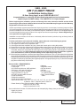
1
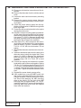
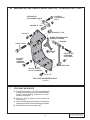
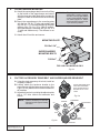
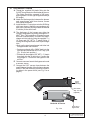
GM 7.
4 Ligh
Supe
t
Truck
r
c
harge
Insta
r Sys
llatio
t
n Ins
truct em
ions
50 St
ate S 1988-199
mog
Lega 5 Model Y
l per
e
CARB ars
EO
#D-21
3-17
®
ENGINEERING, LLC
1650 PACIFIC AVENUE • CHANNEL ISLANDS, CA 93033-9901 • (805) 247-0226
FAX (805) 247-0669 • www.vortechsuperchargers.com • M-F 8:00 AM - 4:30 PM PST
P/N: 4GC020-010
©2001 Vortech Engineering, LLC
All Rights Reserved, Intl. Copr. Secured
15SEP01 V1.1 (88-95 GM Lt Trk(4GC))
FOREWORD
Proper installation of this supercharger kit requires general automotive mechanic
knowledge and experience. Please browse through each step of this instruction manual
prior to beginning the installation to determine if you should refer the job to a professional
installer/technician. Please call Vortech Engineering for installers in your area.
© 2001 VORTECH ENGINEERING, LLC
All rights reserved. No part of this publication may be reproduced, transmitted, transcribed,
or translated into another language in any form, by any means without written permission
of Vortech Engineering, LLC
P/N: 4GC020-010
©2001 Vortech Engineering, LLC
All Rights Reserved, Intl. Copr. Secured
15SEP01 V1.1 (88-95 GM Lt Trk(4GC))
ii
Table Of Contents
FOREWORD ...................................................................................................................... ii
TABLE OF CONTENTS ..................................................................................................... iii
NOTICE .............................................................................................................................. iv
TOOL & SUPPLY REQUIREMENTS .................................................................................. v
PARTS LIST - 1988-1993 7.4 TRUCK ............................................................................... vi
PARTS LIST - 1994-1995 7.4 TRUCK ............................................................................... ix
1.
COMPONENT REMOVAL ...................................................................................... 1
2.
CRANKSHAFT PULLEY INSTALLATION .............................................................. 1
3.
OIL DRAIN LINE ..................................................................................................... 2
4.
OIL FEED LINE ...................................................................................................... 3
5.
SUPPLEMENTARY FUEL INJECTION COMPUTER AND RELATED SYSTEM ... 3
6A.
MAIN BRACKET AND POWER STEERING PUMP - 1988-1993 MODELS .......... 7
6B.
MAIN BRACKET AND POWER STEERING PUMP - 1994-1995 MODELS .......... 8
7.
COOLING FAN SPACER ....................................................................................... 9
8.
SUPERCHARGER MOUNTING ............................................................................. 10
9.
FACTORY ACCESSORY DRIVE BELT AND SUPERCHARGER DRIVE BELT .... 10
10.
DISCHARGE PLENUM .......................................................................................... 11
11.
AIR FILTER, INLET DUCT AND PLENUM ............................................................. 12
12.
FINAL REASSEMBLY & CHECK ........................................................................... 13
iii
P/N: 4GC020-010
©2001 Vortech Engineering, LLC
All Rights Reserved, Intl. Copr. Secured
15SEP01 V1.1 (88-95 GM Lt Trk(4GC))
NOTICE
This product is protected by state common law, copyright and/or patent. All
legal rights therein are reserved. The design, layout, dimensions, geometry,
and engineering features shown in this product are the exclusive property of
Vortech Engineering, Inc. This product may not be copied or duplicated in
whole or part, abstractly or fundamentally, intentionally or fortuitously, nor shall
any design, dimension, or other information be incorporated into any product
or apparatus without prior written consent of Vortech Engineering, LLC.
P/N: 4GC020-010
©2001 Vortech Engineering, LLC
All Rights Reserved, Intl. Copr. Secured
15SEP01 V1.1 (88-95 GM Lt Trk(4GC))
iv
1988 - 1995
GM 7.4 LIGHT TRUCK
Installation Instructions
50 State Smog Legal, as per CARB EO #D-213-17
Congratulations on selecting the best performing and best backed automotive
supercharger available today... the VORTECH® V-2® Supercharger!
Before beginning this installation, please read through this entire instruction booklet and the Street
Supercharger System Owner's Manual which includes the Limited Warranty Program and the Warranty
Registration form and return envelope.
Vortech supercharger systems are performance improving devices. In most cases, increases in torque of 30 to
35% and horsepower of 35 to 45% can be expected with the boost levels specified by Vortech Engineering. This
product is intended for use on healthy, well maintained engines. Installation on a worn-out or damaged engine is
not recommended and may result in failure of the engine as well as the supercharger. Vortech Engineering is
not responsible for engine damage.
Installation on new vehicles will not harm or adversely affect the break-in period so long as factory break-in
procedures are followed.
For best performance and continued durability, please take note of the following key points:
1. Use only premium grade fuel 92 octane or higher (R+M/2).
2. The engine must have stock compression ratio.
3. If the engine has been modified in any way, check with Vortech prior to using this product.
4. Always listen for any sign of detonation (pinging) and discontinue hard use (no boost) until problem is resolved.
5. Perform an oil and filter change upon completion of this installation and prior to test driving your vehicle.
Thereafter, always use a high grade SF rated engine oil or a high quality synthetic, and change the oil and filter
every 3,000 miles or less. Never attempt to extend the oil change interval beyond 3,000 miles, regardless
of oil manufacturer's claims as potential damage to the supercharger may result.
6. Before beginning installation, replace all spark plugs that are older than 1 year or 10,000 miles with original heat
range plugs as specified by the manufacturer and reset timing to factory specifications (follow the procedures
indicated within the factory repair manual and/or as indicated on the factory underhood emissions tag). Do not
use platinum spark plugs unless they are original equipment. Change spark plugs every 15,000 miles and spark
plug wires at least every 50,000 miles.
TOOL & SUPPLY REQUIREMENTS
• Factory Repair Manual
• Hammer
• Timing Light
• Adjustable wrench
• 3/8" socket and drive set: SAE and Metric
• Oil Filter Wrench
• Drill motor, 3/32" and .046" drill bits
• Oil Filter
• 1/2" breaker bar and 4" extension
• SF Rated Quality
• Large screwdriver or pry bar
(or synthetic) Engine oil
• 3/8" NPT tap and handle or socket
• Heavy grease Silicone
• Flat #2 screwdriver
sealer
• Phillips #2 screwdriver
• Center punch and 3/4" drift punch
• Open end wrenches: 3/8", 7/16", 1/2, 9/16", 5/8", 3/4", 7/8", 10, 13 & 15mm
a "Slimline" 19mm - Snap-On part # LTAM1719
• Power Steering Pulley Puller & Installer (1994 models only)
Snap-On Puller #CJ117B2
Snap-On Installer #CJ113B
If your vehicle has in excess of 10,000 miles since its last spark plug change, then you will need:
• Spark plug socket
• NEW spark plugs
v
P/N: 4GC020-010
©2001 Vortech Engineering, LLC
All Rights Reserved, Intl. Copr. Secured
15SEP01 V1.1 (88-95 GM Lt Trk(4GC))
P/N: 4GC020-010
©2001 Vortech Engineering, LLC
All Rights Reserved, Intl. Copr. Secured
15SEP01 V1.1 (88-95 GM Lt Trk(4GC))
vi
1988-1993 7.4 Truck
Part No. 4GC218-090SQ
®
PARTS LIST
ENGINEERING, LLC
IMPORTANT: Before beginning installation, verify that all parts are included in the kit. Report any shortages
or damaged parts immediately.
Part Number
Description
Quantity
2E228-090
V-2SQ SUPERCHARGER ASSEMBLY
1
4GC111-021
4GC010-034
4GC010-043
4GC010-054
4GC011-021
4GC017-011
7A375-550
7F375-016
7K375-040
7J375-044
7A375-100
7C010-025
7A312-100
7J312-000
4GC010-010
7A375-208
7A375-276
7F312-018
4GB017-011
7A375-124
MOUNTING BRACKET ASSEMBLY
Mounting Plate
Attachment Plate
Stiffener plate
Mounting Bracket
.125 Mounting Plate Spacer
3/8-16 x 5-1/2” Bolt
3/8-16 Nuts
3/8” AN960 Flat Washers
3/8” SAE Washers
3/8-16 x 1” Bolts
M10-1.5 x 25mm Bolts
5/16-18 x 1” Bolts
5/16” SAE Flat Washers
Mounting Bracket Support
3/8-16 x 2” Bolt
3/8-16 x 2-3/4” Bolt
5/16-18 Nuts
1” Throttle Spacer
3/8-16 x 1-1/4” Bolts
1
1
1
1
1
1
1
3
5
8
10
2
4
8
1
1
1
4
1
2
4GC116-010
4GB016-011
4GC017-041
7B375-400
7J375-044
7L375-075
4GC017-010
7C080-055
2A046-598
7B500-400
CRANK PULLEY ASSEMBLY
Crank Pulley
Crank Pulley Spacer
3/8-24 x 4” Bolts
3/8” SAE Washers
3/8" Lock Washers
Spacer Fan
M8 1.25 x 55 Studs
Belt
1/2-20 x 4” Bolt
1
1
1
3
3
3
1
4
1
1
4GC130-026
7U030-026
7P525-067
7P250-066
7P250-036
7P125-026
7P250-034
7U100-055
OIL FEED LINE ASSEMBLY
1/4” x 16" Oil Feed hose
.500 Crimp Ferrules
#4 Swivel x 1/4” Hose Barb Fittings
#4 Flare to 1/4” NPT
1/8” NPT 90° Fitting
1/4” NPT x 1/4” NPT Straight Tee
6” Nylon Tie Wraps
1
1
2
2
1
1
1
3
4GC130-036
7R001-008
7U030-036
7P375-033
7P375-017
7U100-055
OIL DRAIN ASSEMBLY
#8 Stainless Hose Clamps
1/2” x 36” Oil Drain Hose
3/8” NPT x 3/8” NPT Street Elbow
3/8” NPT x 1/2” Straight Hose Barb
6” Nylon Tie Wraps
1
2
1
1
1
4
5A001-004
FUEL INJECTION COMPUTER
1
Part Number
4GC112-010
4GB012-010
4GC012-012
4FA012-012
7P375-017
7S350-200
7R002-056
7R002-052
7E010-046
7U035-000
8H040-040
7U030-005
7U035-000
7R001-008
vii
Description
AIR INTAKE ASSEMBLY
Air Filter Cover
Air Inlet Tube
90° Intake Elbow
3/8” NPT x 1/2” Straight Hose Barb
3-1/2” x 2” Sleeve
#56 Hose Clamps
#52 Hose Clamps
#8 x 3/4” Sheet Metal Screws
3-1/2” x 10” Flex Hose
Air Filter
1/2” x 5” Oil Drain Hose
3-1/2” x 12” Flex Hose
#8 Stainless Hose Clamps
Quantity
1
1
1
1
1
1
2
4
2
1
1
1
1
2
4GC112-020
4GB040-060
4GC012-020
4GC050-011
7A312-050
7J312-000
7P125-025
7R002-044
7S275-200
7P750-102
7P750-100
7R002-016
8D001-001
7U030-046
7P156-082
7U034-016
7U034-016
8H040-075
AIR DISCHARGE ASSEMBLY
Air/plenum Gasket
Steel Discharge Tube
Intake Plenum
5/16-18 x 1/2” Bolts
5/16” SAE Flat Washers
1/8” NPT to 5/32” Barb
#44 Hose Clamps
2-3/4” x 2” Sleeves
3/4" NPT x 1" 90° Hose Fitting
3/4" NPT x 1" Straight Hose Fitting
#16 Hose Clamps
Bypass Valve
5/32" x 24" Vacuum Line
5/32" Tee
1" x 3" Heater Hose
1" x 8.5" Heater hose
1" Filter
1
1
1
1
2
2
1
4
2
1
1
4
1
1
1
1
1
1
4FA111-032
7J012-092
4FA011-032
7C012-050
4FA016-150
2A017-010
7C012-020
7C012-022
7G010-175
BELT TENSIONER ASSEMBLY
12mm Flat Washers
Belt Tensioner Plate
12mm x 1.75 x 50mm Bolt
Smooth Pulley Tensioner
Idler Pulley Spacer
12mm x 1.75 x 20mm Bolts
12mm x 1.75 x 22mm Thin Head Bolt
12mm x 1.75 Nut
1
3
1
1
1
1
2
1
1
4GC160-010
4GC152-011
4GB112-022
FUEL CONTROL ASSEMBLY
Spacer Block Assembly
Plenum Rod Assembly
1
1
1
4GB101-002
8F001-002
7R003-024
5W001-011
5W001-001
5W001-010
5W001-014
5W001-015
5W001-017
8F101-200
5W001-002
7R001-008
7P625-001
7U030-050
7J010-001
7F010-032
7U100-055
7C011-075
FUEL PUMP ASSEMBLY
155 Inline Fuel Pump
1-1/2” Adel Clamp
16-14 GA Eyelet
Wire Tap
16-14 GA insulated Female Slides
Fuse Holder
Blade type 20A Fuse
Large Ring Terminal
T-Rex® Wiring Assembly
Fuse Tap
#8 Hose Clamps
Fuel Adapter Fitting
12mm x 8” PCV Hose
#10 Flat Washers
10-32 Nylock Nut
6” Nylon Tie Wraps
10/32” x 3/4” Cap Screw
1
1
1
1
1
6
1
1
1
1
1
2
1
1
4
2
4
1
P/N: 4GC020-010
©2001 Vortech Engineering, LLC
All Rights Reserved, Intl. Copr. Secured
15SEP01 V1.1 (88-95 GM Lt Trk(4GC))
P/N: 4GC020-010
©2001 Vortech Engineering, LLC
All Rights Reserved, Intl. Copr. Secured
15SEP01 V1.1 (88-95 GM Lt Trk(4GC))
viii
1994-1995 7.4 Truck
Part No. 4GG218-090SQ
®
PARTS LIST
ENGINEERING, LLC
IMPORTANT: Before beginning installation, verify that all parts are included in the kit. Report any shortages
or damaged parts immediately.
Part Number
Description
Quantity
Part Number
Description
Quantity
2E228-090
V-2 SQ SUPERCHARGER ASSEMBLY
1
5A001-004
FUEL INJECTION COMPUTER
1
4GG111-021
7A437-600
7J438-081
7A375-300
7F375-016
7K375-040
4GG017-021
4GG017-031
4GG010-034
4GG011-021
4GG010-044
4GG017-041
7J375-044
7A375-100
4GC010-010
7A375-208
7A375-276
4GB017-011
4GG017-043
7K312-001
7C080-025
MOUNTING BRACKET ASSEMBLY
7/16-14 x 6” Bolt
7/16” SAE Washer
3/8-16 x 3” Bolt
3/8-16 Nut
3/8” AN960 Flat Washers
1.895 Spacer A
1.083 Spacer B
Mounting Plate
Mounting Bracket
Attachment Plate
.220 Spacer C
3/8” SAE Washers
3/8-16 x 1” bolts
Mounting Bracket Support
3/8-16 x 2” Bolt
3/8-16 x 2-3/4” Bolt
1” Throttle Spacer
1/2" Spacer
8mm Washers
8mm x 1.25 x 25mm
1
1
1
1
2
7
1
1
1
1
1
1
3
5
1
1
1
1
2
2
2
4FA111-032
7J012-092
4FA011-032
7C012-050
4FA016-150
2A017-010
7C012-020
7C012-022
7G010-175
BELT TENSIONER ASSEMBLY
12mm Flat Washers
Belt Tensioner Plate
12mm x 1.75 x 50mm Bolt
Smooth Pulley Tensioner
Idler Pulley Spacer
12mm x 1.75 x 20mm Bolts
12mm x 1.75 x 22mm Thin Head Bolts
12mm x 1.75 Nut
1
3
1
1
1
1
2
1
1
4GC160-010
4GC152-011
4GB112-022
FUEL CONTROL ASSEMBLY
Spacer Block Assembly
Plenum Rod Assembly
1
1
1
4GC112-010
4GB012-010
4GC012-012
4FA012-012
7P375-017
7S350-200
7R002-056
7R002-052
7E010-046
7U035-000
8H040-040
7U030-005
7U035-000
7R001-008
AIR INTAKE ASSEMBLY
Air Filter Cover
Air Inlet Tube
90° Intake elbow
3/8” NPT x 1/2” straight hose barb
3-1/2” x 2” Sleeve
#56 Hose Clamps
#52 Hose Clamps
#8 x 3/4” Sheet Metal Screws
3-1/2” x 10” Flex Hose
Air Filter
1/2” x 5” Oil Drain Hose
3-1/2” x 12” Flex Hose
#8 Stainless Hose Clamps
1
1
1
1
1
1
2
4
2
1
1
1
1
2
4GB101-002
8F001-002
7R003-024
5W001-011
5W001-001
5W001-010
5W001-014
5W001-015
5W001-017
8F101-200
5W001-002
7R001-008
7P625-001
7U030-050
7J010-001
7F010-032
7U100-055
7C011-075
5W001-024
FUEL PUMP ASSEMBLY
155 Inline Fuel Pump
1-1/2” Adel Clamp
16-14 GA eyelet
Wire Tap
16-14 GA Insulated Female Slides
Fuse Holder
Blade type 20A Fuse
Large Ring Terminal
T-Rex® Wiring Assembly
Fuse Tap
#8 hose Clamps
Fuel Adapter Fitting
12mm x 8” PCV Hose
#10 Flat Washers
10-32 Nylock Nut
6” Nylon Tie Wraps
10/32” x 3/4” Cap Screw
Mini Fuse Tap
4GC130-026
7U030-026
7P500-067
7P250-066
7P250-036
7P125-026
7P250-034
7U100-055
OIL FEED LINE ASSEMBLY
1/4” x 16" Oil Feed Hose
.500 Crimp Ferrules
#4 Swivel x 1/4” Hose Barb Fittings
#4 Flare to 1/4” NPT
90° 1/8” NPT x #4 Fitting
1/4” NPT x 1/4” NPT Straight Tee
6” Nylon Tie Wraps
1
1
2
2
1
1
1
3
4GG116-010
4GB016-011
7B375-400
7J375-044
7L375-075
4GC017-010
2A046-598
4GG017-042
7C080-055
7B500-400
CRANK PULLEY ASSEMBLY
Crank Pulley
3/8-24 x 4” Bolts
3/8” SAE Washers
3/8” Lock Washers
Spacer Fan
Belt
Crank Pulley Spacer
M8 1.25 x 55 Studs
1/2-20 x 4” Bolt
1
1
3
3
3
1
1
1
4
1
4GC130-036
7R001-008
7U030-036
7P375-033
7P375-017
7U100-055
OIL DRAIN ASSEMBLY
#8 Stainless Hose Clamps
1/2” x 36” Oil Drain Hose
3/8” NPT x 3/8” NPT Street Elbow
3/8” NPT x 1/2” Straight Hose Barb
6” Nylon Tie Wraps
1
2
1
1
1
4
4GG112-020
4GC012-020
4GB050-010
7R002-044
7S275-200
4GB040-060
7J312-000
7A312-100
7P125-105
4CB017-011
7P750-102
7P750-100
7R002-016
8D001-001
7U030-046
7P156-082
7U034-016
7U034-016
8H040-075
AIR DISCHARGE ASSEMBLY
Steel Discharge Tube
Intake Plenum
#44 Hose Clamps
2-3/4” x 2” Sleeves
Air/Plenum Gasket
5/16" SAE Flat Washers
5/16-18 x 1” Bolts
1/8” NPT to 5/32” Barb
1/2” Spacers
3/4" NPT x 1" 90° Hose Fitting
3/4" NPT x 1" Straight Hose Fitting
#16 Hose Clamps
Bypass Valve
5/32" x 24" Vacuum Line
5/32" Tee
1" x 3" Heater Hose
1" x 8.5" Heater hose
1" Filter
1
1
1
4
2
1
2
2
1
2
1
1
4
1
1
1
1
1
1
ix
1
1
1
1
1
6
1
1
1
1
1
2
1
1
4
2
4
1
2
P/N: 4GC020-010
©2001 Vortech Engineering, LLC
All Rights Reserved, Intl. Copr. Secured
15SEP01 V1.1 (88-95 GM Lt Trk(4GC))
P/N: 4GC020-010
©2001 Vortech Engineering, LLC
All Rights Reserved, Intl. Copr. Secured
15SEP01 V1.1 (88-95 GM Lt Trk(4GC))
x
1.
COMPONENT REMOVAL
A. Disconnect the battery (negative lead).
B. Remove and set aside the following components:
• The top portion of the fan shroud
• The accessory drive belt
• The cooling fan assembly
• The crankshaft pulley
• The air filter canister assembly and hose
• The intake air resonator (detach from inner
fender)
• The power steering pump pulley (1994
models only)
NOTE: If the vehicle is a 1993 model year or later,
it will be necessary to purchase the stock
air inlet resonator. The Chevrolet part number is 25097949
2.
CRANKSHAFT PULLEY INSTALLATION
A. Remove the crankshaft pulley from the engine if
not already done.
B. Place the Vortech provided crank pulley and
spacer inside the stock pulley. (See Fig. 2-a.)
C. Line up bolt holes and, if necessary, press
pieces together or pull them together by gradually tightening the bolts.
D. Reinstall the pulleys as a unit onto the crankshaft balancer assembly using three 3/8-24 x 4"
bolts and supplied 1/2-20 x 4" center bolt. (See
Fig. 2-a.)
NEW ADDITIONAL PULLEY
SPACER
3 BOLTS: 3/8-24 X 4"
Fig. 2-a
1
P/N: 4GC020-010
©2001 Vortech Engineering, LLC
All Rights Reserved, Intl. Copr. Secured
15SEP01 V1.1 (88-95 GM Lt Trk(4GC))
3.
OIL DRAIN LINE
A. Raise the front of the vehicle and support with
appropriate jack stands.
B. To provide an oil drain for the supercharger, it is
necessary to make a hole in the oil pan. It is best
to punch the hole rather than drill. Remove paint
around the hole area so that it does not flake into
the pan.
C. Make a mark on the oil pan on the driver’s side
ahead of the oil filter. The mark should be 3"
below the bolt flange and rearward of the fourth
bolt 7/8". (See Fig. 3-a.) You may choose a
different place, if necessary; however, take care
not to damage any internal parts. The drain
hose should gradually drop with no dips or kinks
and should be above the oil level.
D. Use a small center punch to perforate the pan
and expand hole. Switch to a larger diameter
punch and expand the hole further to approximately 9/16" diameter. Most punches are made
from hexagon material and may be placed in a
socket with an extension to make this procedure
easier.
E. Tap the hole with a 3/8" NPT tap approximately
1/4" deep. Pack the flutes of the tap with heavy
grease to catch and hold the chips. Once the tap
is removed, it must be cleaned and repacked
before tapping resumes. Use a small magnet to
check for any stray chips in the threads after
completing the tapping procedure.
F. Thoroughly clean the threaded area with acetone or other solvent. Apply a small amount of
silicone sealer to the new threads. Apply a small
amount of silicone sealer to the threads of the 3/
8" NPT hose fitting and secure in hole. Make
sure a seal is formed all around the fitting. Allow
sealer to cure completely.
G. Route the line forward along the top rail of the oil
pan and secure to the oil cooler line with the tie
wraps provided. Temporarily cover end of hose
and secure out of the way. The return is a gravity
drain and should be routed to provide a gradual
drop.
H. Drain and replace engine oil and change filter.
NOTE: This method of rolling over the lip of
the hole and tapping works well if
CAREFULLY done and should cause
no problems.
DOWN 3"
OIL PAN
PUNCH HOLE THROUGH
OIL FILTER
Fig. 3-a
P/N: 4GC020-010
©2001 Vortech Engineering, LLC
All Rights Reserved, Intl. Copr. Secured
15SEP01 V1.1 (88-95 GM Lt Trk(4GC))
2
7/8" TO REAR
OF BOLT
4. OIL FEED LINE
A. The supercharger uses engine oil for lubrication
and must have an oil feed line connected to a
filtered oil access on the engine and an oil return
or drain. (See Fig. 4-a.) Connection to the oil pan
must be above the oil level.
WARNING: The oil system contains a small
orifice that is easily plugged. DO
NOT use any type sealant on
any feed line threads. Instead,
use clean engine oil. Disassemble and blow out entire line
if you have any doubts.
B. Disconnect the wire connector and remove the
oil pressure sending unit. The sender is found
on the left side at the front of the engine block.
Install the TEE provided in the port with the
branch pointing forward. Place the pressure
sender in front branch of the TEE, secure and
reconnect the wire. Place the flare fitting in the
remaining port and secure.
C. Connect the hose to the flare fitting and secure
with tie wraps. Take care that the feed line will
not rub on the sheet metal inner fender.
D. Temporarily cover the end of the hose and
protect it from dirt until connecting to the supercharger.
ENGINE BLOCK
OIL PAN
Fig. 4-a
5. SUPPLEMENTARY FUEL INJECTION COMPUTER AND RELATED SYSTEM
A. Remove the TBI unit from the manifold. (See
Fig. 5-a.) Remove old gaskets and clean the
gasket surfaces.
B. To prevent pressurized fuel and air leakage
around the throttle shaft, it is necessary to
normalize the pressure. To accomplish this,
modify the throttle body by drilling two small
holes from the base surface to the throttle shafts.
You may “layout” the location by following the
template on page 6 or transfer it directly from the
gasket provided. Use a small center drill to start,
then a #56 or 3/64" diameter drill bit and drill
through the base of the throttle body until the bit
firmly contacts the shafts.
C. Assemble the throttle body, the new injector
spacer block and gaskets. Place the gasket with
the small vent holes on top of the spacer. Place
the gasket without holes on the bottom. On
some models dowel pins have been provided
for alignment. Use the two special threaded
rods, nuts and one longer bolt to secure the
throttle body and the Vortech spacer to the
manifold.
3
Fig. 5-a
P/N: 4GC020-010
©2001 Vortech Engineering, LLC
All Rights Reserved, Intl. Copr. Secured
15SEP01 V1.1 (88-95 GM Lt Trk(4GC))
5. SUPPLEMENTARY FUEL INJECTION COMPUTER AND RELATED SYSTEM - Cont'd.
NOTE: Make sure all small holes are aligned and
not plugged with gasket sealer when installed.
D. Mount the additional fuel pump to the inner side
of the frame rail beneath the driver's side floor.
Use the shorter hose provided to help locate the
pump the correct distance from the filter. This
hose has an adapter fitting on the filter end.
Secure the pump to the frame and hose with the
clamp and fastener provided. (See Fig. 5-a.)
E. Mark and drill a 3/16" hole in the frame near the
fuel pump to mount relay and wiring harness.
Mount relay with supplied #10 hardware.
F. From relay terminal #85, tap the yellow wire into
the solid gray wire in the harness running along
the driver's side frame member. Use the supplied scotchlock.
G. Connect the short red wire from relay terminal
#87 to the (+) terminal on the fuel pump.
H. Connect the longer black wire from the (-) terminal at the fuel pump to a clean ground.
I. Connect the short black wire from relay terminal
#86 to a clean ground (relay screw mount works
well).
J. Connect the long red wire from relay terminal
#30 to a (+) battery lug located in the engine
compartment.
K. Plumb the pump to the supplementary injectors
as per the schematic on page 5. Much of this
assembly has been done by Vortech.
L. Plumb the new pressure regulator and outlet,
routing the regulator to the throttle body inlet
using the adapter fitting and O-ring.
M. Route the Vortech SFIC wiring harness and
vacuum line through the firewall. Mount the
SFIC unit inside the vehicle beneath the steering column using the Velcro® strips provided.
N. Connect the wires for the Vortech SFIC. Attach
the black wire to ground. Connect the red to the
"4WD" fuse location in the stock fuse block (this
location is also found on 2WD trucks) with the
special adapter provided (on 1995 models, the
fuse box containing the "4WD" fuse is located
inside the vehicle on the left hand side of the
dashboard). Connect the brown wire to the
negative side of the ignition coil tach pickup
(loose male connection located on coil harness).
P/N: 4GC020-010
©2001 Vortech Engineering, LLC
All Rights Reserved, Intl. Copr. Secured
15SEP01 V1.1 (88-95 GM Lt Trk(4GC))
4
5. SUPPLEMENTARY FUEL INJECTION COMPUTER AND RELATED SYSTEM - Cont'd.
NOTE: Factory fuel return line must be
attached to original fitting on TBI unit.
3/8” HOSE
CONNECT TO FITTING ON
DISCHARGE PLENUM
3/8” BARB
1/4 NPT
FEMALE
USE 3/8" ADAPTER FITTING
AT STOCK FUEL FILTER
PLACE 3/8" ADAPTER FITTING
INTO TBI FUEL INLET
THROTTLE SPACER BLOCK
UPPER
FITTING
LOWER
FITTING
5/16”
BARB x
1/4 NPT
FEMALE
SUPPLEMENTAL
INJECTORS
INJECTOR CONNECTORS ARE
INTERCHANGEABLE AND
REVERSIBLE
5/16”
HOSE
VORTECH FUEL PUMP
RELAY
TERMINAL #87
FUSE BOX
(-) GROUND
25A
FUSE BOX
4WD
BROWN WIRE IGN COIL (-) NEG.
VORTECH
FUEL PRESSURE
REGULATOR
BLACK WIRE GROUND
VORTECH
SUPPLEMENTARY FUEL
INJECTION COMPUTER
(+) FUEL PUMP
87
87a
86
85
30
SOLID GRAY WIRE IN FUEL
PUMP HARNESS (RUNNING
ALONG THE DRIVER'S SIDE
FRAME MEMBER
(+) BATTERY LUG
GROUND
RELAY WIRING
SCHEMATIC
Fig. 5-a
5
P/N: 4GC020-010
©2001 Vortech Engineering, LLC
All Rights Reserved, Intl. Copr. Secured
15SEP01 V1.1 (88-95 GM Lt Trk(4GC))
5. SUPPLEMENTARY FUEL INJECTION COMPUTER AND RELATED SYSTEM - Cont'd.
TEMPLATE
THROTTLE BODY
DRILL TWO HOLES THROUGH BOTTOM OF THROTTLE BODY
UNTIL POSITIVE THROTTLE SHAFT CONTACT
USE 3/64" OR #56 (.046) DIAMETER
.100
.100
4.550
Fig. 6A-a
P/N: 4GC020-010
©2001 Vortech Engineering, LLC
All Rights Reserved, Intl. Copr. Secured
15SEP01 V1.1 (88-95 GM Lt Trk(4GC))
6
6A. MAIN BRACKET AND POWER STEERING PUMP - 1988-1993 MODELS
A. Install the connector bracket to the front of the
stock bracket at the power steering pump with
the two longer metric fasteners provided. Some
vehicles use metric and others use standard
SAE threads. Check the threads on the fasteners you have just removed against the ones
supplied prior to installation. Both metric and
standard fasteners have been provided for your
convenience. Leave the fasteners slightly loose
until all fasteners are started.
B. Position the main supercharger mounting plate
and install the fasteners as shown in the graphic.
Make sure not to forget the 1/8" long tube spacer
behind the plate on the inward bolt.
C. Remove the fastener securing the stock bracket
to the cylinder head on the outward side. Install
the cast aluminum mounting bracket behind the
new mounting plate and on top of the tab on the
stock bracket (where you just removed the
fastener). Place the 3/8-16 x 5-1/2" bolt through
the plate and into the head, passing through the
tab on the stock bracket.
D. Remove the smaller alternator fastener and
install the upper stiffener plate as shown. Do not
secure the stiffener until the supercharger is
installed.
E. Attach the stiffener rod between the cylinder
head and mounting plate. A one inch spacer is
used at the cylinder head as shown in Fig. 6A-a.
F. Secure all other bracket fasteners at this time.
ALTERNATOR
STIFFENER PLATE
.125 SPACER
MOUNTING PLATE
MOUNTING BRACKET
3/8-16 x 1"
1" SPACER
5/16-18 x 1"
STOCK BOLT
3/8-16 x 2-3/4"
3/8-16 x 5-1/2"
SUPPORT
3/8-16 x 1"
3/8-16 x 1" OR
M10-1" x 25
3/8-16 x 2"
POWER STEERING PULLEY
5/16-18 x 1"
ATTACHMENT PLATE
FOR 1988-1993 MODELS
Fig. 6A-a
7
P/N: 4GC020-010
©2001 Vortech Engineering, LLC
All Rights Reserved, Intl. Copr. Secured
15SEP01 V1.1 (88-95 GM Lt Trk(4GC))
6B. MAIN BRACKET AND POWER STEERING PUMP 1994 - 1995 MODELS ONLY
A. Disconnect all electrical connections at the alternator.
B. Remove the alternator from the vehicle and set
aside.
C. Loosen the main cast iron accessory mounting
bracket.
D. Remove the power steering pump fasteners
and set pump aside temporarily. Remove mounting bracket.
E. Locate the power steering pump into the supplied mounting bracket. Install the two right side
bolts finger tight.
F. Fasten the new mounting bracket to the engine
leaving the bolts loose.
G. Attach the Vortech mounting plate by sandwiching the lower left mounting plate hole in between
the mounting bracket and power steering pump.
Use spacer 'C' (0.22") in between the plate and
the power steering pump mounting boss. Use
the original bolt to secure the assembly.
H. Slide spacer 'B' (1.083) in between the mounting bracket and the back of the supercharger
plate as shown in Fig 6B-a. Thread the supplied
7/16-14 x 5-3/4" bolt into the bracket. Do not
tighten.
I. Reinstall the alternator and all electrical connections.
J. Install the attachment plate onto the back of the
alternator mount using the original bolt. Place
spacer 'A' (1.895) in between the attachment
plate and the back of the supercharger mounting plate using a 3/8-16 x 3" bolt, 3/8" nut and
washers.
K. Connect the support rod between the cylinder
head and the rear of the mounting plate. Use the
3/8-16 x 2-1/4" stainless steel bolt and a 3/8-16
x 1-1/2" bolt, nut and washers for attachment. A
1" spacer is used at the cylinder head as shown
in Fig 6B-a. Tighten all bracket fasteners at this
time.
L. Reinstall the power steering pump pulley.
M. 1995 models use a new style ABS control unit
that must be adjusted slightly to provide supercharger clearance. Remove the front two of the
four 8mm bolts fastening the ABS mounting
plate to the vehicle. Pry the front of the ABS
mounting plate up approximately 1/2" to 5/8".
Install the supplied 1/2" spacers underneath the
mounting plate and secure with the supplied
8mm bolts and washers.
P/N: 4GC020-010
©2001 Vortech Engineering, LLC
All Rights Reserved, Intl. Copr. Secured
15SEP01 V1.1 (88-95 GM Lt Trk(4GC))
8
6B. MAIN BRACKET AND POWER STEERING PUMP 1994 - 1995 MODELS ONLY, Cont'd.
FACTORY
ALTERNATOR
BOLT
ALTERNATOR
ATTACHMENT PLATE
SPACER 'A' 1.895
SPACER 'B' 1.083
3/8-16 X 3"
POWER STEERING PUMP
MOUNTING FLANGE
1" SPACER
7/16-14 X 5-3/4"
SPACER
C, .22"
FACTORY
POWER
STEERING
PUMP BOLT
3/8-16
3/8-16 xX2-3/4"
2-1/4"
STAINLESS
STAINLESS
STEEL BOLT
BOLT
STEEL
SUPPORT ROD
3/8-16 X 1" BOLT,
AN 3/8" WASHERS
3/8-16Xx1-1/2"
2"
3/8-16
FOR 1994-1995 MODELS ONLY
Fig. 6B-a
7.
COOLING FAN SPACER
A. Thread the four M8-1-1/4" X 55 threaded studs
into the holes on the water pump to the shoulder.
Loctite® thread locking compound is recommended on threads.
B. Place the 5/8" fan spacer over the studs and
onto the pilot.
C. Place the cooling fan assembly onto the spacer
and secure with the nuts and washers provided.
D. Reinstall the fan shroud upper half.
9
P/N: 4GC020-010
©2001 Vortech Engineering, LLC
All Rights Reserved, Intl. Copr. Secured
15SEP01 V1.1 (88-95 GM Lt Trk(4GC))
8.
SUPERCHARGER MOUNTING
A. Attach the supercharger drain hose to the fitting
on the bottom of the supercharger and secure
with the clamp provided. Make sure to rotate the
clamp so it does not interfere with the mounting
plate.
B. Mount the supercharger to the mounting plate
with the four 3/8 16 x 1" bolts and washers and
one 3/8-16 x 1-1/4" bolt and washer for the plate
stiffener (See Fig. 8-a.) (For 1994-95 models,
the supercharger is mounted with five 3/8-16 x
1" bolts and washers only. The stiffener is not
used.)
C. Attach the oil feed line and secure.
WARNING: The oil system contains a small
orifice that is easily plugged.
DO NOT use any type sealant
on any of the threads. Instead,
use clean engine oil. Disassemble and blow out entire line
if you have any doubts.
MOUNTING PLATE
3/8-16x1-1/4"
SUPERCHARGER
MOUNTING BOLTS
3/8-16x1"
FOR 1988-1993 MODELS ONLY
Fig. 8-a
9.
FACTORY ACCESSORY DRIVE BELT AND SUPERCHARGER DRIVE BELT
A. Using the stock accessory drive belt, install as
originally installed.
B. Loosely attach the tensioner bracket to the
supercharger with the fasteners provided. (See
Figs. 9-a, 9-b.) Make sure to use the washers on
all locations.
C. Adjust belt tension by rotating the adjuster plate
with a 1/2" drive socket and extension and
secure.
MOUNT TENSIONER WITH
SUPPLIED FASTENERS.
NOTE: WASHERS MUST
BE USED ON ALL LOCAMOUNT TENSIONER
TIONS.
WITH
SUPPLIED FASTENERS
YOU MUST USE THE WASHERS
Fig. 9-a
ALTERNATOR
NOTE: It will be necessary to reset the
belt tension after approximately
250 miles.
A/C
ALT
TENSIONER
WATER
PUMP
SUPERCHARGER
TENSIONER
IDLER
POWER
STEERING
Fig. 9-b
CRANKSHAFT
P/N: 4GC020-010
©2001 Vortech Engineering, LLC
All Rights Reserved, Intl. Copr. Secured
15SEP01 V1.1 (88-95 GM Lt Trk(4GC))
10
10. DISCHARGE PLENUM
A. Thread the supplied 90° plastic fitting into the
3/4 NPT bung located on the discharge plenum.
(The fitting should be screwed in until snug,
pointing down & to the right at approximately a
45° angle.)
B. Attach the discharge tube between the plenum
and supercharger with blue sleeves; secure
with clamps as shown.
C. Install the short 1" hose piece onto the 90° fitting
with hose clamps. Attach the supercharger bypass valve (vacuum pointing toward the outside
of vehicle) to the short hose.
D. The discharge of the bypass may either be
routed to atmosphere by using the supplied 1"
K&N® filter (This installation will produce some
air noise on deceleration), or back to the supercharger air inlet tube by using the supplied 1" x
10" hose and 3/4" NPT x 1" plastic fitting. If
routing the air bypass back to the supercharger
inlet:
• Mock-up the steel supercharger inlet tube into
its approximate final location.
• Center punch and drill a 59/64" hole into the
inlet tube and thread with a 3/4" NPT tap. (See
Fig. 10-a for hole position.)
• Thread with the supplied 3/4" NPT x 1" plastic
hose barb into the air inlet tube. Connect the
long length of 1" hose from the bypass to the
air inlet.
E. Connect a vacuum hose to the bypass valve and
a vacuum source.
F. Connect the 5/32" vacuum hose between the
small fitting on the side of the discharge plenum
and the TEE that feeds the pressure normalizing holes in the spacer block (see Fig. 5-a on
page 5).
1-7/8"
Approx.
Center
(Vertically)
Backside of Inlet Tube (Installed)
Drill: 59/64"
Tap: 3/4" NPT
(optional)
Backside of Plenum
Fig. 10-a
11
Supercharger
Bypass Valve
P/N: 4GC020-010
©2001 Vortech Engineering, LLC
All Rights Reserved, Intl. Copr. Secured
15SEP01 V1.1 (88-95 GM Lt Trk(4GC))
11. AIR FILTER, INLET DUCT AND PLENUM
NOTE: On model years 1993 and later, it will be
necessary to replace the resonator unit
with the earlier type prior to modifying.
The Chevrolet part number is 25097949.
A. Modify the stock resonator chamber by cutting
off the end at the point where the radius stops.
(See Fig. 11-a.)
B. Remove the internal baffle tube and deburr the
cut edge.
C. Fit the new end cover, with the air filter element
provided, over the end of the modified resonator. Secure the cover end by drilling two 3/32"
holes (transfer the location from the cover)
and fasten with the self-tapping screws provided.
D. Peel off the protective adhesive cover and
place the plenum gasket on the throttle body
adhesive side down. Lower the discharge plenum on top of the throttle body and secure with
the two acorn nuts and washers provided.
NOTE: Do not overtighten nuts or the plenum will be damaged.
E. Secure the inlet tube to the two bosses on the
front of the plenum with the two 5/16" x 3/4"
fasteners. On some models, the dashpot assembly interferes with the tube. Two spacers
have been provided to correctly position the
inlet.
F. Connect the inlet elbow to the supercharger
inlet using the blue sleeve and clamps provided.
G. Connect the inlet tube and elbow together with
the 3-1/2" diameter flex tube and clamps.
H. Connect the new air filter end cover to the inlet
tube with the 3-1/2" diameter flex tube and
clamps.
I. Attach the crankcase vent from the right valve
cover to the fitting on the inlet tube. Slight
trimming of the plastic vent may be necessary.
VORTECH FILTER AND
END COVER
STOCK RESONATOR
CUT OFF END AT
END OF RADIUS
Fig. 11-a
P/N: 4GC020-010
©2001 Vortech Engineering, LLC
All Rights Reserved, Intl. Copr. Secured
15SEP01 V1.1 (88-95 GM Lt Trk(4GC))
12
12. FINAL REASSEMBLY & CHECK
A. Refit the upper fan shroud.
B. Reconnect the battery.
C. If your vehicle has gone over 10,000 miles since
its last spark plug change, you will need to
change the spark plugs now before test driving
the vehicle.
D. Check all fittings, nuts, bolts and clamps for
tightness. Pay particular attention to oil and fuel
lines around moving parts, sharp edges and
exhaust system parts. Make sure all wires and
lines are properly secured with clamps or tie
wraps.
E. Check all fluid levels, making sure that your
tank(s) is filled with 92 octane or higher fuel
before commencing test drive.
F. Start engine and allow to idle a few minutes,
then shut off.
G. Recheck to be sure that no hoses, wires, etc. are
near exhaust headers or moving parts and for
signs of any fluid leakage. Check ignition timing
to make sure it is set to stock specifications
before commencing test drive.
H. PLEASE TAKE SPECIAL NOTE: Operating
the vehicle without the Supplementary Fuel
Injection Computer or any other subassemblies completely and properly installed and working may cause FAILURE OF MAJOR ENGINE
COMPONENTS.
I. Test drive the vehicle.
J. The supercharger drive belt stretches initially
and will require adjustment between 250 and
400 miles.
K. Read the STREET SUPERCHARGER SYSTEM OWNER'S MANUAL AND WARRANTY
REGISTRATION FORM within thirty (30) days
of purchasing your supercharger system to
qualify.
Fig. 12-a
WARNING: Do not attempt to operate the vehicle until ALL components are
installed and ALL operations are
completed including final check.
13
P/N: 4GC020-010
©2001 Vortech Engineering, LLC
All Rights Reserved, Intl. Copr. Secured
15SEP01 V1.1 (88-95 GM Lt Trk(4GC))
®
ENGINEERING, LLC
1650 PACIFIC AVENUE • CHANNEL ISLANDS, CA 93033-9901 • (805) 247-0226
FAX (805) 247-0669 • www.vortechsuperchargers.com • M-F 8:00 AM - 4:30 PM PST
P/N: 4GC020-010
©2001 Vortech Engineering, LLC
All Rights Reserved, Intl. Copr. Secured
15SEP01 V1.1 (88-95 GM Lt Trk(4GC))