1
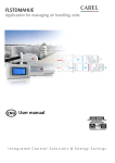
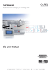
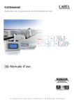
INSTALLATION
&
OPERATION MANUAL
Single Package
Vertical Air Conditioning System
B – Series
18,000 – 24,000 – 30,000 – 36,000 –
42,000 – 49,000 – 60,000 Btuh
840-170-38
TABLE OF CONTENTS
Vert-I-Pak B-Series Vertical Air
Conditioning System
Page
I.
II.
III.
1.
2.
3.
4.
IV.
2
Safety Considerations .......................................................................................................
3
General Recommendations ...............................................................................................
3
Unpacking and Inspecting the Unit ....................................................................................
3
Supplies Needed for Installation ........................................................................................
3
General Specifications
Model Number Identification Guide ...................................................................................
4
B-Series Chassis Specifications ........................................................................................
4
Dimensional Data
V(E,H)B18,24,30,36 Unit Dimensions ................................................................................
5
V(E,H)B24,49 Unit Dimensions .........................................................................................
6
V(E,H)B60 Unit Dimensions ..............................................................................................
6
Installation
Indoor and Outdoor Air Requirement .................................................................................
4-5
A. Outdoor Air System .......................................................................................................
7-9
B. Ducted Condenser Air ..................................................................................................
10
Outdoor Fan Performance ..................................................................................
10
C. Indoor Air (Conditioned Supply air System ..................................................................
11
Indoor Fan Performance .............................................................................................
12
Electrical
A. Grounding ...........................................................................................................
12
B. Power Supply ......................................................................................................
12
Thermostat Mounting and Wiring ...................................................................................... 13-14
A. Thermostat Location ...........................................................................................
13
B. Thermostat Mounting & Wiring ...........................................................................
13
C. Wire Thermostat Cable to Unit Terminal .............................................................
13
Condensate Drain Line ......................................................................................................
14
Installation – Final Checklist ..............................................................................................
14
Test Run ...........................................................................................................................
14
Owners Manual & Operating Information
Identifying your System .....................................................................................................
15
Important Facts .................................................................................................................
15
Operating the Vert-I-Pak ....................................................................................................
16
Thermostat Operation .......................................................................................................
16
Cooling Cycle ....................................................................................................................
17
Heating Cycle ....................................................................................................................
17
Defrost Cycle .....................................................................................................................
17
Performing Routing Maintenance ......................................................................................
18
Replace the Air Filter .........................................................................................................
18
Inspect and Cleaning the Indoor Air Coil ............................................................................
19
Inspect the Outdoor Air Intake and Exhaust ......................................................................
19
Inspect and Clean the Condensate Drain ..........................................................................
19
SAFETY CONSIDERATIONS
Improper installation, adjustment, alteration, service, maintenance, or use can cause explosion, fire, electrical shock, or other
conditions which may cause personal injury or property damage. Consult a qualified installer, service agency, or your distributor
or dealer for information and assistance. The qualified installer or agency must use factory-authorized parts or accessories when
modifying this product. Refer to the individual instructions packaged with the parts or accessories when installing.
Follow all safety codes. Wear safety glasses and work gloves. Read these instructions thoroughly and follow all warnings or
cautions attached to the unit. Always install units in accordance with local building codes, the National Electric Code (NEC),
and the Installation Standards, Warm Air Heating and Air Conditioning Systems ANSI/NFPA 90B for special installation
requirements.
GENERAL RECOMMENDATIONS (DO'S AND DON'T'S)
●
●
●
●
●
●
●
●
●
●
●
●
●
●
●
●
●
●
●
DO read the instructions completely before installation.
DO take time to perform a quality installation.
DO NOT obstruct or restrict indoor or outdoor air paths.
When using flex duct: DO install properly. DO NOT crush or make sharp bends in flex duct, use only gradual bends.
DO tape and seal all duct joints.
DO check the indoor conditioned air duct system static pressure losses. It should not exceed those listed in Table 2.
Consult your dealer or distributor for more information.
When designing indoor supply systems, DO NOT reduce air intakes or discharge sizes.
DO insulate ALL conditioned air duct system components.
DO NOT locate room thermostat near conditioned air diffusers.
DO locate thermostat on an interior wall.
DO check that condensate drain line drains freely.
DO NOT let debris fall and collect in indoor or outdoor blowers.
DO NOT drill into unit (except for 1 in. flanges for ducted return units). This could cause a refrigerant leak.
DO handle unit with care.
DO provide minimum installation and service clearances.
DO build closet so that unit may be removed if necessary.
DO follow all guidelines for indoor and outdoor air system.
DO NOT substitute any components without checking with your dealer or distributor. If you do substitute, get approval
in writing. Substitutions without approval void unit warranty.
DO NOT guess, consult your dealer or distributor if any portion of the installation procedure is unclear.
UNPACK AND INSPECT UNIT
Remove shipping protection and pallet from unit and inspect for damage. Be sure to check for concealed internal shipping
damage. Do not install a damaged unit.
SUPPLIES NEEDED FOR INSTALLATION
The following items are required to install unit.
●
Adhesive, aluminum duct tape.
CAUTION: Incorrect type of duct tape may be a fire hazard. A failure to follow this warning could result in a fire and
personal injury or death.
●
6-conductor thermostat cable (20 gage wire minimum).
CAUTION: Do not use thermostat wire with less than the recommended number of conductors.
●
●
●
●
●
Supplies to connect indoor air (conditioned air supply) duct to unit.
Supplies to connect power to unit.
Supplies to connect outdoor-air duct to unit.
Supplies to connect condensate drain line.
Supplies to connect low-voltage thermostat to unit.
3
Section I – General Specifications
VERT-I-PAK® MODEL IDENTIFICATION GUIDE
MODEL NUMBER
SERIES
V=Vertical Series
E=Cooling with or without electric heat
H=Heat Pump
DESIGN SERIES
A = 32" Cabinet
B = 68" Cabinet
NOMINAL CAPACITY
B-Series (Btu/h)
18 = 18,000 36 = 36,000 60 = 60,000
24 = 24,000 42 = 42,000
30 = 30,000 49 = 49,000
VOLTAGE
K = 208/230V-1Ph-60Hz
V
H
B
36 K 10 RT A
ENGINEERING CODE
OPTIONS
RT = Standard Remote Operation
ELECTRIC HEATER SIZE
B-Series
05 = 5.0 KW
10= 10.0 KW
15 = 15.0 KW
20 = 20.0 KW
25 = 25.0 KW
B-SERIES CHASSIS SPECIFICATIONS
M O D E L S :
C O O L I N G
V(E,H)B18K05
V(E,H)B24K05
V(E,H)B24K10
V(E,H)B30K10
V(E,H)B30K15
V(E,H)B36K10
V(E,H)B36K15
Cooling Cap.
17000
17000
22000
22000
30000
30000
35000
35000
Cooling Power (W)
1700
1700
2200
2200
2900
2900
3500
3500
SEER
10.0
10.0
10.0
10.0
10.0
10.0
10.0
10.0
Cooling SHR
0.78
0.78
0.75
0.75
0.70
0.70
0.70
0.70
E L E C T R I C A L
Heater Size (KW)
H E A T
D A T A :
5.0
10.0
5.0
10.0
10.0
15.0
10.0
15.0
Heating Cap. (Btu/h)
17050
34100
17050
34100
34100
51150
34100
51150
Heating Power (W)
5000
10000
5000
10000
10000
15000
10000
15000
Heating Current (A)
20.8
41.6
20.8
41.6
41.6
62.4
41.6
62.4
H E A T
P U M P
D A T A :
Heating Cap. (Btu/h)
17000
17000
22000
22000
30000
30000
34000
34000
Heating Power (W)
1650
1650
2000
2000
2600
2600
3300
3300
Heating Current (A)
7.3
7.3
9.3
9.3
12.0
12.0
15.0
15.0
COP
3.0
3.0
3.2
3.2
3.2
3.2
3.0
3.0
230/208
230/208
230/208
230/208
230/208
230/208
230/208
230/208
42.5
42.5
56.0
56.0
72.5
72.5
88.0
88.0
(14) 26
(14) 52
(16.7) 26
(16.7) 52
(22.8)52
(22.8)26,52
(27.9)52
(27.9) 26,52
Hard Wire
Hard Wire
Hard Wire
Hard Wire
Hard Wire
Hard Wire
Hard Wire
Hard Wire
E L E C T R I C A L
Voltage (V)
LRA - Comp. (A)
Min. Ckt. Amps (A)+
Power Connection
P H Y S I C A L
D A T A :
D A T A :
Unit Width (in.)
30.00
30.00
30.00
30.00
30.00
30.00
30.00
30.00
Unit Depth (in.)
21.00
21.00
21.00
21.00
21.00
21.00
21.00
21.00
Unit Height (in.)
68.00
68.00
68.00
68.00
68.00
68.00
68.00
68.00
320
320
320
320
330
330
340
340
1050
Shipping Weight (lbs.)
A I R F L O W
4
V(E,H)B18K10
D A T A :
D A T A :
Indoor CFM
640
640
800
800
1000
1000
1050
Fresh Air CFM
65
65
65
65
65
65
65
65
Indoor Motor
1/3
1/3
1/3
1/3
1/3
1/3
1/3
1/3
Indoor Motor Amps
1.0
1.0
1.0
1.0
1.8
1.8
2.5
2.5
Outdoor Motor
1/3
1/3
1/3
1/3
1/3
1/3
1/2
1/2
Outdoor Motor Amps
1.4
1.4
1.4
1.4
2.2
2.2
3.0
3.0
M O D E L S :
C O O L I N G
V(E,H)B42K10
V(E,H)B42K15
V(E,H)B49K15
V(E,H)B49K20
V(E,H)B60K20
V(E,H)B60K25
D A T A :
Cooling Cap.
42000
42000
48500
48500
58000
58000
Cooling Power (W)
4500
4500
5500
5500
6450
6450
SEER
9.8
9.8
9.8
9.8
9.9
9.9
Cooling SHR
0.72
0.72
0.69
0.69
0.72
0.72
E L E C T R I C A L
Heater Size (KW)
H E A T
15.0
15.0
20.0
20.0
25.0
Heating Cap. (Btu/h)
34100
51150
51150
68200
68200
85250
Heating Power (W)
10000
15000
15000
20000
20000
25000
Heating Current (A)
41.6
62.4
62.4
83.2
83.4
104.2
P U M P
D A T A :
Heating Cap. (Btu/h)
40000
40000
47000
47000
59000
59000
Heating Power (W)
4000
4000
4800
4800
5636
5636
Heating Current (A)
19.0
19.0
22.0
22.0
25.0
25.0
COP
3.0
3.0
3.0
3.0
3.0
3.0
230/208
230/208
230/208
230/208
230/208
230/208
104.0
104.0
129.0
129.0
169.0
169.0
(33) 52
(33) 26,52
(40.5) 26,52
(40.5 ) 52,52
(49) 52, 52
(49), 26, 52, 52
Hard Wire
Hard Wire
Hard Wire
Hard Wire
Hard Wire
Hard Wire
E L E C T R I C A L
Voltage (V)
LRA - Comp. (A)
Min. Ckt. Amps (A) +
Power Connection
P H Y S I C A L
D A T A :
D A T A :
Unit Width (in.)
38.00
38.00
38.00
38.00
45.00
45.00
Unit Depth (in.)
28.00
28.00
28.00
28.00
30.50
30.50
Unit Height (in.)
68.00
68.00
68.00
68.00
77.00
77.00
440
440
460
460
540
540
1800
Shipping Weight (lbs.)
A I R F L O W
Indoor CFM
Value in ( ) is for the unit
power. Value outside of ( )
is for electric heat only. See
Page 12.
D A T A :
10.0
H E A T
+
D A T A :
1400
1400
1400
1400
1800
Fresh Air CFM
70
70
70
70
70
70
Indoor Motor
1/2
1/2
1/2
1/2
1/2
1/2
Indoor Motor Amps
3.0
3.0
3.0
3.0
3.1
3.1
Outdoor Motor
3/4
3/4
3/4
3/4
1/3 (2)
1/3 (2)
Outdoor Motor Amps
4.7
4.7
4.7
4.7
5.0
5.0
Section II – Dimensional Data
Figure 1
V(E,H)B18,24,30,36 Unit Dimensions (Inches)
CONDENSATE
DRAIN EXIT 2"
ABOVE FLOOR
5
Figure 2
V(E,H)B42, 49 Unit Dimensions (Inches)
Figure 3
V(E,H)B60 Unit Dimensions (Inches)
Section III – Installation
TheVert-I-Pak was designed for installation in residential and light commercial applications. These instructions detail a
typical method of installation. Figure 4 shows the typical component location and airflow paths through the unit.
Units are available in three return air configurations: front "free-return" with disposable filter; front ducted return with 1"
duct flange; and left side ducted return with 1" duct flange. See Figure 10 on Page 11.
6
Figure 4
Unit Configuration
1) INDOOR AND OUTDOOR AIR REQUIREMENTS
The indoor and outdoor air systems are designed to operate at specified airflow rates and external static pressures. The supply
and return air duct system pressure losses (including filter, louver/grille and registers) must not exceed the listed external
static pressures for either the indoor or outdoor air systems.
CAUTION: Failure to adhere to indoor air and outdoor air requirements as listed in the following sections will void unit
warranty.
A.
Outdoor Air System
As a completely self-contained system, the Vert-I-Pak unit requires an adequate supply of outdoor air to exchange heat from
the outdoor air coil. The outdoor air intake and discharge openings are located on the back side of the unit. The unit may
be installed where the outdoor air path runs through the wall of the building directly behind the unit or where the outdoor air
intake and discharge paths are ducted separately away from the unit. Figure 9 shows two typical ducted OA designs.
CAUTION: To ensure proper operation, the outdoor air intake and discharge air paths must be free and unobstructed.
The two air paths must be situated to ensure that the intake and discharge air do not recirculate (also called short-circuit).
7
Figure 5
VPBWP3 – 8/14 Wall Plenum
For Models
• VE/VHB18
• VE/VHB24
Figure 6
VPBWP4 – 8/14 Wall Plenum
For Models
• VE/VHB18
• VE/VHB24
• VE/VHB30
• VE/VHB36
8
Figure 7
VPBWP5 – 8/14 Wall Plenum
For Models
• VE/VHB42
• VE/VHB49
Figure 8
VPBWP6 – 8/14 Wall Plenum
For Model
• VE/VHB60
9
B.. Ducted Condenser Air
For ducted outside air applications, the combined pressure losses of the intake and discharge air paths must not exceed
the external static capabilities of the system at the design airflow (See Table 3).
Outdoor Fan Performance
Table 1
Model
0.1
0.2
0.3
0.4
0.5
VE/HB18
1300
1180
1100
950
790
VE/HB24
1300
1180
1100
950
790
VE/HB30
1300
1200
1100
1000
810
VE/HB36
1730
1660
1600
1560
1400
VE/HB42
2100
2000
1900
1800
1700
VE/HB49
2600
2500
2400
2300
2100
VE/HB60
2990
2900
2800
2670
2450
Note: Italic type indicates performance outside the required operating
window of ± 10% of rated SCFM.
Figure 9
Typical Ducted Outside Air Configuration
INTAKE
EXHAUST
EXHAUST
CEILING
CEILING
BACK
OF
UNIT
OUTDOOR
AIR INTAKE
OUTSIDE
WALL
OUTDOOR
AIR
INTAKE
OUTSIDE
WALL
OUTSIDE
WALL
FLOOR
OUTDOOR AIR
EXHAUST
FLOOR
OUTDOOR
AIR EXHAUST
INTAKE
10
C. Indoor-Air (Conditioned Supply Air) System
The VEB/VHB series unit may be applied in either a free return air configuration or a ducted return air configuration. The supply
air path is intended to be ducted. The design and construction of the indoor-air system must provide adequate air distribution
to ensure comfort levels throughout the structure.
The combined pressure losses of the return and supply air paths must not exceed the external static capabilities of the system
at the design airflow (See Table 2).
If the unit is installed in a closet behind a door and the return air louver or grille is directly opposite the unit RA opening, 2in. clearance is required between the front of the unit and the back side of the louver or grille. If the louver or grille is located
elsewhere on the door so it is not directly in front of the RA opening, a minimum of 7-in. clearance is required between the
front of the unit and the back side of the door. The minimum "net free open area" required for the RA louver or grille is listed
in Table 2.
Indoor Fan Performance
Table 2
Indoor Blower Air Flow, SCFM (ARI RATED as shown)
ESP
0.1
0.2
0.3
0.4
Model
VE/HB18
VE/HB24
VE/HB30
VE/HB36
VE/HB42
VE/HB49
VE/HB60
Indoor
Indoor
Indoor
Indoor
Indoor
Indoor
Indoor
850
980
1120
1220
1570
1670
1980
750
890
1070
1120
1510
1610
1920
640
800
1000
1050
1470
1570
1860
550
720
940
990
1400
1500
1800
RA Grille Minimum Net
Free Open Area (Sq. In.)
0.5
450
650
830
860
1350
1450
1700
250
300
375
400
525
525
675
Note: Italic indicates performance outside the required operating window of +/- 10% of rated SCFM. All values are wet
coil with filter installed.
Figure 10
Front Free
Return
Return Air Options
Front Ducted
Return
Side Ducted
Return
NOTE: Ducted return air configurations require field fabrication of a duct-mounted filter box. Filters are not
supplied with units configured for ducted return.
11
2) Electrical
DANGER: Electrical shock hazard. Turn OFF electric power at the fuse box or service panel before making any
electrical connections and ensure a proper ground connection is made before connecting line voltage. Failure to do
so can result in property damage, personal injury and/or death.
A. Grounding
CAUTION: The unit must be electrically wired and grounded in accordance with all state and local codes, national electric
code, and NFPA 70. Unit and controls will NOT operate unless properly grounded. A ground lug is provided for ground
connection. Use only approved copper wire and connectors from unit to service panel.
B. Power Supply
NOTE: Line voltage circuit is completely factory wired. Make all line voltage connections inside circuit breaker junction box.
The circuit breakers or fuses used for branch circuit protection should be UL recognized. If circuit breakers are used, the circuit
breaker for the compressor circuit must have a UL HACR rating. If fuses are used, the fuse for the compressor circuit MUST
be time delay type.
CAUTION: Units are dual voltage rated 208-230/1/60. The 24V control transformer must be connected for either 208V
or 240V power source for proper operation. Line voltage must not exceed 253V or go below 197V. The transformer
connection must be changed for 208V operation.
Heat Strip Data
Cooling and Fan
Circuit Data
Depending on auxiliary heater size, unit must be supplied with 2 or 3 separate 208V or 240V circuits from structure’s fuse
box or service panel. Each circuit is internally connected to a circuit breaker located in the unit control box located at the
front center of the unit. Refer to Table 4 and Table 5 for required circuits and recommended wire size for each circuit.
1
2
3
Model
Com pressor Am ps
V(E,H)B18
V(E,H)B24
V(E,H)B30
V(E,H)B36
V(E,H)B42
V(E,H)B49
V(E,H)B60
Heater Size
(KW)
5.0
10.0
15.0
20.0
25.0
Outdoor Fan Am ps Indoor Fan Am ps
Minim um Circuit
Am pacity
Maxim um Fuse 2 or
Breaker Size Am ps
Minim um Wire Size 1
9.3
1.4
1.0
14.0
12
20
11.4
1.4
1.0
16.7
12
25
15.0
2.2
1.8
22.8
10
30
17.9
3.0
2.5
27.9
8
40
20.4
4.5
3.0
33.0
8
50
26.4
5.0
3.0
41.0
6
60
32.1
5.0
3.1
49.0
6
60
Chassis
Available
Ckt #1 Am ps
Ckt #1
Am pacity
Ckt #1 Wire
Size 1
Ckt #1 Max.
Fuse 2
Ckt #2 & 33
Am ps
Ckt #2 & 33
Am pacity
Ckt #2 & 33
Wire Size 1
Ckt #2 & 33
Max. Fuse 2
18/24
20.8
26.0
10
30
N/A
N/A
N/A
N/A
18/24/30/36/42
41.6
52.0
6
60
N/A
N/A
N/A
N/A
30/36/42/48
20.8
26.0
10
30
41.6
52.0
6
60
48/60
41.6
52.0
6
60
41.6
52.0
6
60
60
20.8
26.0
10
30
41.6
52.0
6
60
If wire is applied at ambient greater than 30°C (86°F), consult Table 310-16 of the NEC (ANSI/NFPA 70). The ampacity of nonmetalic-sheathed
cable (NM), trade name ROMEX, shall be that of 60°C (140°F) conductors, per the NEC (ANSI/NFPA 70) Article 336-30. If other than uncoated (nonplated), 60°C or 75°C (140°F or 167°F) insulation, copper wire (solid wire for 10 AWG and smaller, stranded wire for larger than 10 AWG) is used,
consult applicable tables of the NEC (ANSI/NFPA 70).
Time-delay fuse.
Circuit #3 is only used for 25kw heater.
Heat Pump
(Field Wiring)
Heat Pump
Auxiliary
Heater #1
(Field Wiring)
Auxiliary
Heater #1
Ground
(Field Wiring)
Ground Lug
Auxiliary Heater #2
(Field Wiring)
Auxiliary
Heater #2
Line Voltage And Ground Connections
12
Unit Wiring with VPDB1 Distribution Block
3) THERMOST
AT MOUNTING AND WIRING
THERMOSTA
A. Thermostat Location
Locate the thermostat about 5 ft. above the floor in an area with good circulation at average indoor temperature.
Do not mount the thermostat where it may be affected by:
•
Drafts or dead-air spots behind doors and in corners.
•
Hot or cold air flow from ducts.
•
Radiant heat from sun or appliances.
•
Concealed pipes or chimneys.
•
Unheated (uncooled) areas behind thermostat, such as an outside wall.
B. Thermostat Mounting and Wiring
The thermostat is a precision instrument and was carefully adjusted at the factory. Handle it carefully.
CAUTION: Disconnect the power supply before beginning installation of the thermostat to prevent electrical shock
or equipment damage. Do not short across the thermostat terminals. This can burn out the thermostat anticipator.
All wiring for the thermostat circuit must comply with NEC, state and local codes. Use No. 20 AWG color-coded,
insulated (35°C minimum) wire. If the thermostat is located more than 100 ft. from the unit (as measured along the
control voltage wires), use No. 18 AWG color-coded wires to avoid excessive voltage drop.
1. In replacement applications, check the existing thermostat wiring for cracked or frayed insulation. Replace any
wiring in poor condition. All wiring must comply with local codes and ordinances.
2. Run wiring (if necessary) to the location. Thread the wires through a hole in the packing material saved in Step 2.
Connect the wires to the terminals on the back of the thermostat. (See Figure 11.)
3. Push the excess wire back through the hole and plug any opening with packing material to prevent drafts that may
affect thermostat performance.
4. Loosely secure the thermostat to the wall with screws through the two mounting holes in the middle of the thermostat.
5. Level the thermostat. Tighten the two mounting screws.
6. Replace the thermostat cover.
C. W
ire Thermostat Cable to Unit T
erminal Strip
Wire
Terminal
Attach thermostat wires to low-voltage terminal block on left side of control box in locations indicated in Figures 1, 2 & 3.
Figure 11
Thermostat
Wiring
G
R
Fan
Y
Compressor
24V
G
B
R
W2
Auxiliary
Heat
Reversing
Valve
Y
E
B
C
Common
Emergency
Heat
W2
E
X
13
4)
CONDENSA
CONDENSATE
TE DRAIN LINE
The condensate drain exits the unit 2" above floor level at the right side front corner of the unit. The condensate drain line
is already internally trapped therefore, no external condensate trap is required.
Install a condensate drain line of the same size as the drain fitting on the unit. PVC plastic pipe (3/4 in. I.D.) makes an ideal
condensate line (if local codes allow).
Run condensate drain line from unit to floor drain or outside perimeter of building per local codes.
The condensate line must have a minimum drop of 1/4" per running foot as it leaves the unit. When a horizontal run of 15
ft. or longer is required, it may be necessary to install a vent tee in the drain line near the unit or use a larger diameter drain
line. This is to eliminate air trapping and allow proper condensate drainage.
Heat pumps generate condensate during both cooling and heating modes. Condensate drain line must be protected from
freezing to prevent condensate from backing up in unit during freezing outdoor conditions.
NOTE: If the unit is to be installed in an attic or furred space where damage may result from condensate overflow, it may
be necessary to provide a field-supplied secondary drain pan. Always refer to local and national codes.
INSTALLATION - FINAL CHECKLIST
!
!
Is power to the unit ON?
!
Is ductwork sealed for an airtight
!
fit?
Are circuit breakers/power
disconnect inside of the unit
ON?
!
Is the condensate drain line
Is the thermostat level and
properly installed?
!
installed and run to an
appropriate disposal site.?
Is the heat anticipator indicator
set to the correct setting.?
Test Run
Test run in Heating, Cooling, and Emergency Heat mode as follows:
a.
Set fan control to ON. If fan runs, return control to AUTO setting. This verifies fan is working properly.
b.
Set system control from OFF to COOL. Lower temperature selector to 50°F or lower. The compressor should
energize and cool air should flow from room registers. Once cooling test is complete, return system control to OFF
setting. Wait 5 minutes.
c.
Set system control to HEAT and raise temperature selector to 80°F or higher. Compressor should energize, and
warm air should flow from room registers.
d.
Set system control to EM HEAT (Emergency Heat). Compressor should turn off and warm air should continue to
flow from the registers. (This step is for heat pumps only.)
NOTE: During EM HEAT operation, temperature of air flowing from room registers may be slightly warmer than
during normal HEAT mode operation.
Leave both Installation Manual and Users Manual with owner or user of equipment.
After 72 hours of operation, the unit will achieve full rated operating performance.
14
Section IV – OWNER'S MANUAL AND OPERATING
INFORMATION
IDENTIFYING YOUR SYSTEM
Take the time to familiarize yourself with the type of system you have. This knowledge will be of use in understanding the
basic operation of your unit.
A self-contained unit, like the Vert-I-Pak, has all of its major components in one cabinet located inside your home. The unit
does not have a separate outdoor unit like a traditional “split-system” air conditioner or heat pump. Figure 4 shows the
location of the major components inside the cabinet.
The product model and rating data label is affixed to the unit front panel and provides the necessary information for specific
identification of the unit. You should familiarize yourself with the model and serial numbers listed on the label.
IMPORTANT FACTS
To better protect your investment and to eliminate unnecessary service calls, familiarize yourself with the following facts:
Your system should never be operated without a clean air filter properly installed. A dirty, clogged air filter will increase
operating costs and shorten the life of the unit. The air filter should be replaced as it becomes dirty.
Supply-air and return-air registers should not be blocked. Restricted airflow reduces the efficiency and life span of your
unit.
For your system to function properly, it MUST have a constant supply of outdoor air to the outdoor air coil located inside
the unit. The outdoor-air intake and exhaust openings are located on the back side of the unit. Familiarize yourself with the
outside air openings on the building and check to ensure that they are not obstructed.
Thermostat
Your multipurpose indoor thermostat is the control center for your comfort system. You should familiarize yourself with its
proper operation. Attempting to control the system by other means – for instance, switching the electrical supply power ON
and OFF – may cause damage to the unit.
With some thermostats, increasing the HEAT mode temperature set point more than 2°F may cause the auxiliary electric
heaters to operate to satisfy the call for heating. To minimize energy costs, do not increase the HEAT mode temperature
set point by more than 2°F at a time.
Depending on the design of your home and its ventilation ductwork and registers, areas of warm or cool air may develop
throughout the home. Operating the unit with the fan switch “ON” increases air mixing throughout the home and reduces
temperature variations within the home.
Dehumidification
During the cooling season, the Vert-I-Pak also dehumidifies the air in the home while is it cooling the air. After a few minutes
of operation, water should run freely from the condensate drain line extended to the outside of your home. If condensate
is not running from the drain line, check to be sure that the drain hose or pipe is properly connected to the drain fitting located
on the bottom of the unit which is accessible from beneath the home. Check the drain line periodically during the cooling
season to ensure the condensate is running freely from outside the home and draining away from the home’s foundation.
(Note: in lower humidity climates, the indoor air may be too dry to generate condensate during the cooling mode.)
Heat Pump
If you are a first-time owner of an all-electric heat pump, the operating characteristics of the system may be different than
you are accustomed to as compared to conventional electric resistance, gas or oil furnaces. Air entering a conventional
furnace at 60°F may be warmed 60° to 100°F. The supply air leaving the registers would then be between 120° and 160°F
depending on the system. A heat pump warms the same 60°F air 20° to 30°F. The supply air leaving the registers would
then be between 80° and 90°F. This air may feel cool because it is slightly less than your body temperature. However, it
is sufficiently warm to keep you comfortable and is adding heat to your home. A heat pump will run for much longer periods
of time than a conventional furnace. This longer operational time is normal for all heat pumps and is saving you energy in
comparison to many conventional furnaces. On days with outdoor temperatures below 40°F, it is normal for the heat pump
15
to run for extended periods of time and may be assisted by the auxiliary electric resistance heating elements. Once you
understand the operation of your new heat pump, you will appreciate its constant, even heat and lower energy consumption.
Heat Mode Operation
During the heat mode of operation, frost or ice may build up on the outdoor-air coil after operating for extended periods during
particularly cool and humid weather. When this occurs, your heat pump senses this condition and goes through a defrost
cycle. During the defrost cycle, the outdoor-air blower is turned off, and the reversing valve reverses the flow of refrigerant
through the outdoor-air coil so it is heated and the frost or ice melts. You may notice the defrost cycle inside your home by
a faint click and hissing sound and a slight change in the sound created by the blower as the defrost cycle begins and ends.
During the defrost cycle, you may also notice that the air is quickly heated as the defrost cycle ends. Outside the home, a
cloud of water vapor created by the melting frost or ice may be visible as it is exhausted. This is normal and keeps the unit
working efficiently. Do not be alarmed!
Condensate
The heat pump may generate condensate during both the cooling and heating modes of operation. For proper operation,
a condensate drain line must be extended from the drain fitting on the right side of the unit to the perimeter of the home
or to a proper drain location. The drain line must be sloped towards the outside of the home or drain location and be protected
from freezing.
NOTE: In order for condensate to drain freely, the unit must be installed level.
OPERATING THE VERT-I-PAK
THERMOSTAT OPERATION
The operation of the system is controlled by the indoor thermostat. Most thermostats have 3 controls: a temperature control
selector, a FAN control, and a SYSTEM or MODE control. (See Figure 3.)
The temperature control is a selector or set of buttons that allows you to establish the degree of temperature that you wish
to maintain for your personal comfort. Some thermostats have two temperature control selectors: one for setting the
temperature desired during the cooling cycle, and one for setting the heating operation temperature.
Typical settings are 78°F for cooling and 68°F for heating.
Fan Control
The FAN control offers two options for controlling the indoor-air blower: AUTO and ON. When the FAN control is set to
AUTO, the blower will operate only while the thermostat operates the cooling or heating equipment. When the FAN control
is set to ON, the blower will operate continuously – regardless of whether cooling or heating equipment is operating. This
setting allows for continuous air circulation and filtration.
16
System Control
The SYSTEM or MODE control on your thermostat offers the following selections: COOL, OFF, HEAT, and EM HEAT. Neither
the cooling nor heating equipment will operate when the SYSTEM or MODE control is set to OFF. With the SYSTEM or MODE
control set to COOL, your unit will operate in cooling mode. With the SYSTEM or MODE control set to HEAT, your unit will
operate in heating mode.
Auxiliary Heating
Your system also includes an auxiliary electric heating source. The SYSTEM or MODE control options HEAT and EM HEAT
provide convenient selection between the two heating appliances. The heat pump will operate when SYSTEM or MODE control
is set to HEAT. The auxiliary electric heater may also be used on cold days to supplement heat pump heating. With the
SYSTEM or MODE control set to EM HEAT, the heat pump is turned off and the auxiliary electric heat is activated. The unit
is now operating as an electric furnace.
On heat pump systems, the wall thermostat regulates the use of auxiliary electric heat to maximize energy efficiency and
your home comfort.
COOLING CYCLE
When operating in the cooling cycle, your unit will operate until the indoor temperature is lowered to the level you have selected
on the indoor thermostat. On extremely hot days, your unit will operate for longer periods of time and have shorter “off” periods
than on moderate days.
The following are typical conditions that add extra heat and/or humidity to your home and force your cooling unit to work longer
to keep your home comfortable:
•
•
•
•
•
•
Entrance doors are frequently opened and closed.
Laundry appliances are being operated.
A shower is running.
More than the usual number of people are present in the home.
More than the normal number of electric lights are in use.
Drapes or blinds are open on the sunny side of the building or home.
HEATING CYCLE
With the SYSTEM control of your indoor thermostat set to HEAT, the heating section of your home comfort system will operate
until room temperature is raised to the level you have selected. Of course, the heating unit will have to operate for longer periods
to maintain a comfortable environment on cooler days and nights than on moderate ones. When the demand is greater than
the capacity of the heat pump alone, the auxiliary electric heaters will supplement the heat pump.
NOTE: Non-Heat Pump models use a single stage heat thermostat. When a demand for heat is made,
these units will use the electric heat strip heat immediately.
DEFROST CYCLE
When your heat pump is providing heat to your home and the outdoor temperature drops below 45°F, moisture may begin
to freeze on the surface of the outdoor-air coil. If allowed to build up, this ice would impede airflow across the coil and reduce
the amount of heat absorbed from outside air. To maintain energy-efficient operation, your heat pump has an automatic defrost
cycle.
The defrost cycle will occur only if ice is sufficient to interfere with normal heating operation. After ice is melted from the outdoorair coil, the unit automatically switches back to normal heating mode.
Do not be alarmed if steam or fog appears at the outdoor-air exhaust during the defrost cycle. Water vapor from the melting
ice may condense into a mist in the cold outdoor air.
17
PERFORMING ROUTINE MAINTENANCE
With the proper maintenance and care, your system will operate economically and dependably. Maintenance can be
accomplished easily by referring to the following directions. However, before performing any maintenance, consider these
important safety precautions:
WARNING: Electrical Shock Hazard. Before attempting any service work or routine maintenance, turn off all electrical
connections to the unit. Failure to do so may result in property damage, personal injury and/or death.
CAUTION: Although great care has been taken to minimize sharp edges in the construction of your unit, be extremely
careful when handling parts or reaching into the unit.
REPLACE AIR FILTER
A dirty air filter reduces the efficiency of your Vert-I-Pak and allows lint and dirt to accumulate on the indoor-air coil. Lint and
dirt on the indoor-air coil can damage your unit and void the warranty. The air filter should be replaced as it becomes dirty.
To replace the filter (front air return units):
1. Slide the filter to the right until it clears the filter rails (See Figure 12).
2. Remove the filter.
3. Install new disposable filter.
CAUTION: Do not operate your system without a filter in place, nor block the front of the unit return air opening.
Filter Replacement
Figure 12
Filter Rails
Air Filter
To remove the filter,
slide it to the right side
of the unit as shown.
Removing the Filter From the Front Filter Rack
18
INSPECT AND CLEAN INDOOR-AIR COIL
Eventually, minor amounts of lint and dirt may pass through the filter and collect on the indoor-air coil. These minor
accumulations can be carefully vacuumed away with a brush attachment on a vacuum cleaner. Care must be taken to avoid
bending the aluminum fins on the coil. Bent fins should be straightened using a special fin tool available from most HVAC
service technicians.
INSPECT OUTDOOR-AIR INTAKE AND EXHAUST
The unit’s outdoor-air intake and outdoor-air exhaust paths must remain clear. Check the OA exhaust frequently. Keep it
free of all debris, snow, or ice. The OA intake should also be kept free of obstructions. Blocking the OA exhaust or OA intake
opening will reduce the efficiency of your unit, could damage it, and void your warranty.
INSPECT AND CLEAN CONDENSATE DRAIN
The condensate drain must be routed to a suitable drainage area. Check the unit condensate drain periodically. Keep it free
of anything that may block or impede the flow of condensate water. If there is any accumulation of foreign matter in the drain
pipe, it should be removed and cleaned. The entire drain line must be protected from freezing.
19
Use Factory-Certified Parts
FRIEDRICH AIR CONDITIONING CO
CO..
Post Office Box 1540 • San Antonio, Texas 78295-1540
4200 N. Pan Am Expressway • San Antonio, Texas 78218-5212
(210) 357-4400 • FAX (210) 357-4480
www.friedrich.com
Printed in the U.S.A.
20