1
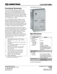
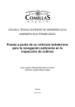
Victoreen® 05-437
Primalert® 35 Area Radiation Monitor
Operators Manual
March 2005
Manual No. 126011 Rev. 3
©2003, 2005 Fluke Corporation, All rights reserved. Printed in U.S.A.
All product names are trademarks of their respective companies
Fluke Biomedical
Radiation Management Services
6045 Cochran Road
Cleveland, Ohio 44139
440.498.2564
www.flukebiomedical.com/rms
Table of Contents
Section 1:
1.1
1.2
Introduction................................................................................................ 1-1
Product Description ..................................................................................... 1-1
Specifications............................................................................................... 1-2
Section 2:
2.1
2.2
2.3
2.4
2.5
2.6
Getting Started........................................................................................... 2-1
Receiving Inspection.................................................................................... 2-1
Mounting ...................................................................................................... 2-1
Power........................................................................................................... 2-1
Optional Power ............................................................................................ 2-2
Routine Cleaning ......................................................................................... 2-2
Attaching a Ground Wire.............................................................................. 2-2
Section 3:
3.1
3.2
3.3
3.4
Operation.................................................................................................... 3-1
Set up .......................................................................................................... 3-1
Testing ......................................................................................................... 3-1
Setting the Alarm Level................................................................................ 3-1
Alarm Reset ................................................................................................. 3-1
Section 4:
4.1
Maintenance ............................................................................................... 4-1
Maintenance ................................................................................................ 4-1
i
(Blank page)
Introduction
Product Description
1
Section 1
Introduction
1.1 Product Description
The Primalert® 35 Area Radiation Monitor provides reliable, continuous monitoring of radioactive
materials. Six front panel, color-coded LED's (1, 2, 4, 8,16, and 32 mR/h) indicate an increase or
decrease in radiation level. The LED for each level lights as the radiation reaches that level and goes out
as the radiation drops below that level.
Visual and aural alarms are user-set to activate at anyone of the six levels via a front-panel screwdriveradjustable control. When the preset level is exceeded, bright flashing red lights (visible over a 1800 field)
and a loud intermittent signal are activated. The alarms stop automatically when the radiation level falls
below the preset value. The aural alarm indicators may be selected/deselected via a front panel switch.
Fail-safe operation is assured by continuous visual (front panel LED) indication of background radiation.
The unit is designed not to jam or indicate false readings at high radiation levels.
The Primalert 35 includes a jack to allow attachment of an optional Primalarm (Model 05-434) at a remote
location up to 100 feet from the main unit. The Primalarm provides both audible and visual warnings.
Figure 1-1
Primalert 35 Area Radiation Monitor
1-1
Victoreen 05-437
Operators Manual
1.2 Specifications
Detector
Energy-compensated G-M tube
Energy Dependence
10% to 40% from 50 KeV to 2 MeV, as referenced to 137Cs
Overload Protection
Alarms in fields higher than 100 R/h when detector is completely blocked for
pulse operation.
Operation Indicator
Provide continuous visual indication of background radiation.
Range/lndicators
1 mR/h: Green
2 mR/h: Green
4 mR/h: Yellow
8 mR/h: Yellow
16 mR/h: Red
32 mR/h: Red
Response Time
Level
1 mR/h
Response Time
3 seconds
2 mR/h
1.5 seconds
4 mR/h
800 milliseconds
8 mR/h
400 milliseconds
16 mR/h 200 milliseconds
32 mR/h 100 milliseconds
Alarms
Alarm may be preset by user at any indicated discrete level by means of the
front panel selector switch; front panel switch selects all alarms or visual
only.
Visual Alarm: bright incandescent red lamps flashing on/off approximately
1/sec.
Aural Alarm: 400 Hz tone, alternating 1/sec; sound level = 76 db at one
foot.
Operating Conditions
10° C to 40° C (50° F to 104° F)
Maximum of 90% relative humidity (non-condensing)
External Connectors
Jack located on case bottom allows attachment
alarm (Primalarm) at remote location.
Power Supply
Part 14-314 (United States, Canada)
Input 117 VAC, 60 Hz, 12 W
Output 12 VDC, 500 mA
Part 14-400 (Europe)
Input 230 VAC, 50 Hz,
Output 12 VDC, 500 mA
Part 14-417 (United Kingdom)
1-2
of external aural/visual
Introduction
Specifications
1
Input 230 VAC, 50 Hz, 13.8 W
Output 12 VDC, 580 mA
Part 14-417, Part 14-416 (Australia)
Dimensions
5.9 in. high x 3.4 in. wide x 13 in thick Unit clips to wall with removable
mounting clip.
Accessories Supplied
Appropriate 115V (230) CE approved converter
P/N 102007: Wall Mounting Bracket
P/N 74: Spare Lamp
Available:
P/N 05-441: PrimaPak™ II Backup Battery Pack
P/N 05-434: Primalarm™ Remote Alarm unit.
P/N 62-103: Check-source, 137Cs, 10 μCi, License Exempt
1-3
Victoreen 05-437
Operators Manual
(Blank page)
Getting Started
Receiving Inspection
2
Section 2
Getting Started
2.1 Receiving Inspection
Upon receipt of the unit:
1. Inspect the carton(s) and contents for damage. If damage is evident, file a claim with the
carrier and notify Fluke Biomedical, Radiation Management Services at 440.248.9300.
2. Remove the contents from the packing material.
3. Verify that all items listed on the packing list have been received and are in good condition.
NOTE
If any of the listed items are missing or damaged, notify
Fluke Biomedical.
2.2 Mounting
The mounting bracket supplied (P/N 102007) may be attached to any convenient vertical mounting
surface. Before mounting the bracket to the wall, however, make sure that the 6 ft. converter power cord
will reach the nearest power outlet.
The wall-mounting bracket comes supplied with double-sided foam tape already attached. Just peel off
the protective paper covering and firmly apply to the mounting surface.
CAUTION
Once in place the bracket cannot be moved or
removed without destroying the tape. Make sure of
your installation site before applying.
2.3 Power
The plug on the end of the converter power cord should first be inserted into the larger jack on the bottom
of the Primalert. The converter should then be plugged into the wall outlet.
Note that when first connected to power, the Primalert may alarm for as long as three seconds before the
automatic reset is actuated.
2-1
Victoreen 05-437
Operators Manual
2.4 Optional Power
The Primapak II storage battery supplies a source of 12-16 Volt DC power to the Primalert using the
converter plug connection. The plug is a Switchcraft #760, or equivalent, with the sleeve negative and pin
positive. The current drain at background radiation levels is about 25 mA, and about 250 mA at full alarm
levels.
The optional Primapak II Back-up Battery Pack, Model No. 05-441, is available as an optional power
source for the Primalert. The Primapak II consists of rechargeable gel cells and circuitry that switches the
Primalert to battery operation if line power is lost. When AC power is present, the battery is automatically
recharged. Fully charged cells provide approximately eight hours of operation under alarm conditions or
more than 32 hours of operation. The Primapak II includes a 120VAC/16VAC converter and interconnect
cable.
2.5 Routine Cleaning
CAUTION
Do not immerse the Model 05-437 Primalert. The
unit is not waterproof. Liquid could damage the
circuits. The unit should be kept clean and free
from dirt and contamination. The unit may be
cleaned by wiping with a damp cloth using any
commercially available cleaning or decontaminating
agent.
2.6 Attaching a Ground Wire
If required, use the following procedure to attach a separate ground wire to the instrument:
1. Loosen the screw in the center of the back cover.
2. Remove the back cover.
3. Attach a wire to the ground terminal by running it up through the small hole between the jacks.
NOTE
At least #16 gauge wire should be used for this
purpose.
4. Replace and secure the back cover.
2-2
Operation
Set Up
3
Section 3
Operation
3.1 Set Up
The only set-up required for the Primalarm is the attachment of one end of the power cord (converter) to
the unit and the other end into a properly grounded AC outlet as noted in Section 2.
When power is first applied to the unit, the alarm and one or more of the LED's may light. After a
maximum of three seconds, the indicators will extinguish and the alarm will reset.
The unit should now be operational with the OPERATION INDICATOR LED flashing on or off with each
background pulse received.
The Primalert 35 is a fully digital preset count instrument. The measurement and reset time are
dependent on count rate. Refer to the response time specifications listed in Section 2.
3.2 Testing
Test the unit for proper operation by positioning the check source (P/N 62-103) as indicated on the front
panel. With the check source label down, the Primalert 35 should indicate between 2 and 8 mR/h; with the
label up, it should indicate between 1 and 4 mR/h.
3.3 Setting the Alarm Level
The Alarm Level may be set with a small screwdriver from the front panel. Alarm levels from 1 to 32 mR/h
may be set. When the radiation exceeds the setting, the alarm will be actuated.
3.4 Alarm Reset
The alarm reset on the Primalert 35 is automatic and both aural and visual alarms will stop when the
radiation level drops below the Alarm Level setting.
3-1
Victoreen 05-437
Operators Manual
(Blank page)
Maintenance
Maintenance
4
Section 4
Maintenance
4.1 Maintenance
WARNING
This instrument contains CMOS integrated circuits.
No service should ever be attempted unless by a
qualified service technician thoroughly familiar with
these devices. Static charges normally present in a
dry atmosphere or leakage current in soldering
irons or other non-grounded tools can instantly
destroy CMOS integrated devices. If this device
has I.C. sockets, do not even attempt to remove or
replace them.
WARNING
Failure to conduct periodic performance test in
accordance with ANSI N323.1978, Paragraphs 4.6
and 5.4, and to keep records thereof in accordance
with Paragraph 4.5 of the same standard, could
result in erroneous readings or potential danger.
ANSI N323.1978 becomes, by this reference, a part
of this document.
An assembly drawing (Figure 4-1), schematic diagram (Figure 4-2), PC board component layout (Figure
4-3), and applicable parts lists (Tables 4-1 and 4-2) are provided for the user's reference.
Table 4-1. Main Assembly (126028) Parts List
Item No.
5
6
7
8
9
12
14
16
17
18
Part No.
126021
126026
126027
102009
102008
500002
0960008
5-1078
5-99
5-26
Description
PC B Assembly
Panel
Case
Reflector
Lens
SPDT Switch
Parker 2-006 O-ring
Screw, 5-20 XI
Screw, 1-72 x 3/16
Screw, 4 x .25
Qty
1
1
1
1
1
1
1
1
2
3
4-1
Victoreen 05-437
Operators Manual
Table 4-2. PC Board Assembly (126021) Parts List
Item No.
6
7
Ref. No.
V1
U1, 4
Qty
1
2
D1
Part No.
Description
010054
Tube Shield Assembly
630001 IC, Quad Nor Gate, 4001 UB
IC, Quad Nand Gate, 4011
630002
UB
630006
IC, Quad Latch, 4043B
IC, 12 Stage Counter,
630008
4040BE
600005
Diode 1N5243B
8
U7
9
U5, 6
10
U2, 3
12
13
14
15
16
17
18
D2, 3,4
D5, 6
Q1, 2
Q4-9
Q11, 12
11,2
600001
Diode 1N4006RL
600003
Diode1N414B
620001
Transistor 2N4124
620003 Transistor, S.C.R. MCR-103
620003
Transistor, MPS-A13
680009
REDT-1 Hi-Intensity LED
3
2
2
6
2
2
19
20
23
24
25
26
13,4
15-7
A1
U8
680008
680007
710002
640001
5-196
5-764
2
3
1
1
1
1
27
28
29
30
4-2
31
110-11
32
110-11
33
34
T1
A1
35
C1
36
C8, 14,16, 17
37
38
C13, 15,23
C5, 7,20
39
C6, 22
40
C9, 10,11
41
C21
42
C3, 4
45
R2, 5-10,37
Yellow T-1 LED
Green T-1 LED
12 VDC Audio Alarm
IC, +6 V Regulator, 78M06
Screw, PH, 4-40 x .38
Washer, INT, 4, s, CP
5-850
Nut, Hex, 4-40, 5, CP
0911403 Screw, BH, 6-32 x .25, 5
5-766
Washer, INT, 6, 5, CP
0976002 Binding Post, 6-32 PCB MNT
Lamp Holder, T-1 3/4 PCB
780006
MNT
Lamp, T-1, 3/414 V @ 1A,
680010
#74
780013
Microphone Jack
780014
Power Jack
Cap, Film, 2200 PF, 250 V,
212221
10%
Cap, Film, .01 μF, 250 V,
211031
10%
211032
Cap, .01 μF, 100 V, 20%
211041 Cap, Film, .1 μF, 160 V, 10%
Cap, Tant, 2.2 μF, 16 VDC,
232252
20%
201031 Cap, .01 μF, 1000 V, 20%
Cap, Film, .47 μF, 100 VDC,
214741
10%
201021 Cap, 1000 PF, 500 V, 20%
Resistor, Film, 510k, .25W,
185-1434
5%
1
2
2
1
1
1
1
1
2
2
1
1
1
4
3
3
2
3
1
1
8
Maintenance
Maintenance
46
47
49
50
51
52
53
54
55
57
58
59
60
61
63
R22, 23
302041
Resistor, Film, 200k, .25W,
5%
Resistor, Film, 100k, .25W,
5%
Resistor, Film, 10k, .25W,
R27, 29,31, 34,40 341032
5%
Resistor, Film, 200, .25W,
R13-18, 28
185-1448
5%
R24
185-2496 Resistor, Film, 2k, .25W, 5%
Resistor, Film, 20k, .25W,
R25, 41
342031
5%
Resistor, Film, 3.3m, .25W,
R21, 39
303351
5%
Trim Pot, 1M, .5w, 20%,
R3
391052
Open
R36
300501 Resistor, Film, 5.1, .25W, 5%
T1
700003
Transformer, H.V., OSC
S1
560009
Switch, Rotary, 6-pos,
44-16 Washer, Flat, .25 ID/.41 OD
33-139Socket, 16-Pin IC, PCB MNT
16
33-139Socket, 14-Pin IC, PCB MNT
14
Double-sided Tape, 3/4 x 1
0998002
1/16
R20, 26,30,
32,33,38,
341041
4
2
6
5
7
1
2
2
1
1
1
1
1
4
3
1RL
4-3
Victoreen 05-437
Operators Manual
Figure 4-1
4-4
Primalert 35 Assembly (126028)
Maintenance
Maintenance
Figure 4-2
4
Primalert 35 Schematic (126015)
4-5
Victoreen 05-437
Operators Manual
Figure 4-3
4-6
PC Assembly (126021)
Fluke Biomedical
Radiation Management Services
6045 Cochran Road
Cleveland, Ohio 44139
440.498.2564
www.flukebiomedical.com/rms