1
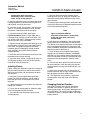
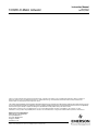
Instruction Manual
Form 5417
February 2007
1035/El-O-Matic Actuator
Type 1035/El-O-Matic
Rack-and-Pinion Rotary Actuator
Contents
Introduction . . . . . . . . . . . . . . . . . . . . . . . . . . . . . . . 1
Scope of Manual . . . . . . . . . . . . . . . . . . . . . . . . . 1
Description . . . . . . . . . . . . . . . . . . . . . . . . . . . . . . 2
Specifications . . . . . . . . . . . . . . . . . . . . . . . . . . . . 2
Installation . . . . . . . . . . . . . . . . . . . . . . . . . . . . . . . . 4
Operation . . . . . . . . . . . . . . . . . . . . . . . . . . . . . . . . . 5
Adjustment . . . . . . . . . . . . . . . . . . . . . . . . . . . . . 11
Troubleshooting . . . . . . . . . . . . . . . . . . . . . . . . . . 11
Maintenance . . . . . . . . . . . . . . . . . . . . . . . . . . . . . 11
Actuator Disassembly . . . . . . . . . . . . . . . . . . . . 12
Actuator Assembly . . . . . . . . . . . . . . . . . . . . . . . 14
Changing Rotation Direction . . . . . . . . . . . . . 15
Spring Return E Series Actuators . . . . . . . . . 16
Spring Return P Series Actuators . . . . . . . . . 17
Installing the Bypass Valve . . . . . . . . . . . . . . 18
Parts Ordering . . . . . . . . . . . . . . . . . . . . . . . . . . . . 18
Parts Kits . . . . . . . . . . . . . . . . . . . . . . . . . . . . . . . . 19
Parts List . . . . . . . . . . . . . . . . . . . . . . . . . . . . . . . . 20
Introduction
Scope of Manual
This instruction manual includes installation,
maintenance, and parts ordering information for
Type 1035/El-O-Matic rack-and-pinion rotary
actuators (figure 1). These actuators are available in
both double-acting and spring-return (figure 2)
configurations. Spring return units provide fail action
in response to spring compression. The actuator is
field reversible. Instructions for the valve and for any
accessories used with the actuator are found in
separate manuals.
Figure 1. Type 1035/El-O-Matic Actuator
with Type A41 Valve
this manual. If you have any questions about these
instructions, contact your Emerson Process
Managementt sales office before proceeding.
Note
Neither Emerson, Emerson Process
Management, nor any of their affiliated
entities assumes responsibility for the
selection, use and maintenance of any
product. Responsibility for the
selection, use, and maintenance of any
product remains with the purchaser
and end-user.
D500243X012
Do not install, operate, or maintain a Type 1035
actuator without first D being fully trained and
qualified in valve, actuator, and accessory
installation, operation, and maintenance, and D
carefully reading and understanding the contents of
W9255
www.Fisher.com
Instruction Manual
Form 5417
February 2007
1035/El-O-Matic Actuator
Table 1. Specifications
Type 1035 Actuator:
Double Acting
EDA 25
EDA 40
EDA 65
EDA 100
EDA 200
EDA 350
EDA 600
EDA 950
EDA 1600
PDA 2500
PDA 4000
Spring Return
ESA 25
ESA 40
ESA 65
ESA 100
ESA 200
ESA 350
ESA 600
ESA 950
ESA 1600
PSA 2505
PSA 4005
Output Shaft: J Double D insert for Type A41
valves J Optional ISO 5211 square insert,
J Recessed ISO 5211 square drive for P Series
actuators
Dual Stop Adjustment: J E Series actuators are
furnished with dual stop adjustments (DSA) as a
standard feature. J P Series actuators provide
dual stops with the use of the “Limit Stop Plate”
(LSP) option. The LSP is mounted between the
actuator and yoke.
Supply Pressure(1) (Operating Pressure)
2.8 to 8.3 bar (40 to 120 psig) for both double
acting and spring return actuators
Temperature Range(1)
Standard: –20 to 79_C (–4 to 175_F) with Nitrile
O-rings
Optional:
High Temperature: –20 to 121_C (–4 to 250_F)
with fluorocarbon O-rings (a ‘‘V” in model
number), or Low Temperature: –40 to 79_C (–40
to 175_F) with EPDM and special lubricant (an
‘‘LT” in model number)
Performance Characteristics
See tables 2 and 3
Rotation for Code A Construction
Rotation is counterclockwise with port ‘‘A’’
pressurized with standard code A construction.
Spring return actuators fail clockwise with
standard construction for standard code A
actuators (see figure 3 for optional constructions)
Maximum Output Torque
See Catalog 14
Lubrication
Factory lubricated for the normal life of the
actuator (see temperature range shown above)
Coating
All units feature a two component polyurethane
coating system as standard
Actuator Tubing Size
3/8 inch O.D. standard for all sizes
Options
J Parts kits: O-ring kits provides O-rings only,
and repair kits provide O-rings, guide bushings
and soft parts. Kits are available for standard and
high temperature or for low temperature
applications
J Unit is field reversible
1. The pressure-temperature limits in this manual and any applicable code or standard installation should not be exceeded.
2. For more information, contact your Emerson Process Management sales office.
Description
The Type 1035 actuator is a rack-and-pinion,
pneumatic quarter-turn actuator. The actuator
utilizes a double rack and single pinion design (see
figure 2). The actuator uses three carbon filled PTFE
guide bands, with a balanced piston which prevents
metal-to-metal contact between the pistons and
cylinder wall.
The E Series actuator uses a recessed bushing
2
inserted into the end of the actuator drive shaft.
Standard recessed double-D bushings match the
Type A41 valve drive shaft. In most applications, the
valve shaft is inserted directly into the recessed
actuator shaft bushing. The P Series actuators
provide a recessed square output shaft for coupling
the actuator to the valve shaft. The Type A41 valve
uses a square-to-double-D drive coupler
construction. Optional couplings are available for
other applications.
Instruction Manual
Form 5417
February 2007
1035/El-O-Matic Actuator
Table 2. Performance Characteristics
BORE
STROKE
E SERIES
ACTUATOR
SIZE
mm
Inch
mm
Inch
E25
56
2.2
15.7
0.62
E40
70
2.8
18.8
0.74
AVERAGE
STROKE
TIME
(SEC)(1)
FREE AIR VOLUME(2)
FREE AIR
VOLUME(2)
Port
‘‘B’’(in3)
Port
‘‘A’’(liter)
Port
‘‘A’’(in3)
Port
‘‘B’’(liter)
0.5
0.1
6.1
0.11
6.7
0.7
0.16
9.8
0.22
13.4
E85
80
3.1
22.0
0.87
1.1
0.33
20.1
0.36
22.0
E100
91
3.6
25.1
0.99
1.2
0.35
21.4
0.49
29.9
E200
110
4.3
37.7
1.48
2.2
0.8
48.8
1.0
61.0
E350
145
5.7
37.7
1.48
3.7
1.8
110
1.9
116
E600
175
6.9
44.0
1.73
3.3
2.9
177
3.1
189
E950
200
7.9
50.3
1.98
5.4
4.7
287
4.9
299
E1600
230
9.1
62.8
2.47
5.8
7.3
445
8.0
488
P2500/P2505
300
11.8
56.5
2.22
6.7
8.0
488
9.3
567
P4000/P4005
325
12.8
81.7
3.22
12.4
13.5
824
17.5
1068
1. These times assume smaller solenoids for smaller actuators and larger solenoids for larger actuators with varying Cvs, but a constant air supply pressure of 80 psi (5.51 bar). E25 to
E350 assume a 0.09 Cv (0.08 Kv); E600 & E9500 a 0.26 Cv (0.22 Kv); E1600, P2505 & P4005 a 0.51 Cv (0.44 Kv).
2. To calculate air consumption per stroke multiply free air volume X air supply pressure (absolute).
STANDARD SQUARE END
COUPLER
DOUBLE ACTING
ACTUATOR
SPRING
END CAP SPRING RETURN
DOUBLE D CONNECTION
STANDARD SQUARE
E SERIES INSERT
W6954 / IL
Figure 2. Typical Actuator Assembly
3
Instruction Manual
Form 5417
February 2007
1035/El-O-Matic Actuator
Table 3. Approximate Weights
kg
lbs
ACTUATOR
SIZE
EDA
ESA
EDA
ESA
E25
1.2
1.7
2.7
3.7
E40
1.8
2.4
4.0
5.3
E65
2.4
3.6
5.3
7.9
E100
2.8
4.6
6.1
10.1
E200
5.8
9.1
12.8
20.1
E350
10.4
16.9
22.9
37.3
E600
19.4
27.6
42.8
60.8
E900
26.4
38.6
58.2
85.0
E1600
42.7
65.8
94.1
145
P2500/P2505
56.7
88.0
125
194
P4000/P4005
86.2
132.0
190
291
Table 4. Bolting Torques between 1035 and Yoke
ACTUATOR
SIZE
Bolt Diameter,
Inches
Torque, NSm
Torque, lbfSft
E25
1/4
11
8.3
E40
E65
E100
5/16
22
16.5
E200
E350
3/8
39
29
E600
1/2
91
67
E950
5/8
163
120
E1600
3/4
258
190
P2500/P2505
P4000/P4005
3/4
203
150
Installation
When an actuator and a valve are shipped together,
the actuator is normally mounted on the valve.
Follow the valve body instructions when installing
the control valve in the pipeline. If the actuator is
shipped separately from the valve or if it is
necessary to mount the actuator on the valve,
perform the procedures in the Actuator Mounting
section.
WARNING
Always wear protective gloves,
clothing, and eyewear when
performing any installation operations
to avoid personal injury.
To avoid personal injury or property
damage caused by bursting of
pressure-retaining parts, be certain the
service conditions do not exceed the
limits given in table 1. Use
pressure-limiting devices or
4
pressure-relieving devices to prevent
the cylinder pressure from exceeding
these limits.
If hoisting the valve and actuator
assembly or the actuator by itself, take
precautions to prevent people from
being injured in case the hoist or sling
slips unexpectedly. Refer to table 3 for
actuator weights. Carefully position
the sling to prevent damage to tubing
or any accessories.
Check with your process or safety
engineer for any additional measures
that must be taken to protect against
process media.
If installing into an existing
application, also refer to the WARNING
at the beginning of the Maintenance
section in this instruction manual.
Actuator Mounting
Use the following steps to connect a valve and
actuator that has been ordered separately.
The Type 1035 E Series is offered with a Double D
insert as standard to allow direct coupling to the
Type A41 valve drive shaft. A few actuator/valve
combinations will require the use of an external
coupler: E100 with a 1-inch drive shaft, E200 and
E350 with a 1-1/2-inch drive shaft.
P Series applications, the actuators feature an ISO
5211 recessed square drive shaft and requires an
external coupler to engage the valve drive shaft. P
Series actuators also require the use of a Limit Stop
Plate (LSP) if a Type 1080 Declutchable Manual
actuator is not being used.
Assemble the bracket, actuator, LSP (if necessary)
and valve assembly as follows:
1. Rotate the valve drive shaft to the position
necessary to match the valve/actuator operation.
See figure 3 for mounting style codes and positions.
2. Attach the yoke/mounting bracket to the actuator
or the LSP (if necessary). Do not fully tighten cap
screws at this time. You will need to align the valve
and actuator, or valve, coupler, LSP and actuator
before tightening the mounting screws to the
required torque. The 5/8-inch screws should not be
used to mount the actuator to the yoke/mounting
bracket. These screws are only to be used for
mounting the LSP. Only the 3/4-inch screws are to
Instruction Manual
Form 5417
February 2007
1035/El-O-Matic Actuator
be used to mount the actuator to the yoke/mounting
actuator.
WARNING
Exceeding any torque requirement
may impair the safe operation of this
actuator by causing broken or
damaged parts. Refer to table 4 for
bolting torque requirements.
The LSP, if used, will also have to be attached to the
Type 1035. Use 4 screws for size P2500/P2505 and
8 screws for size P4000/P4005. The bolting torque
for these 5/8-inch screws will be 10.2 NSm (90 inSlb).
3. The P Series and a few E Series actuator
combinations require a coupler. Insert the square
end of the coupler into the drive shaft recess in the
actuator, making sure the coupler engages properly.
4. Lower the actuator, and coupling assembly onto
the valve, making sure that the male valve stem
engages into the coupler or insert.
Actuator Orientation: The Type 1035 actuator is
normally installed with its major axis parallel to the
pipeline (see code A, figure 3). However, the
actuator can also be oriented 90 degrees to the
pipeline. See figure 3 for standard and optional
orientations. (Note: Code B is not available in the E
Series.)
The P or E Series actuator drive shaft turns a full 90
degrees and the stroke is adjustable for the valve
closed position. When necessary, refer to the
actuator adjustment steps in this manual.
Note
The Type A41 High Performance
Butterfly valve should not be turned by
the power actuator more than 90
degrees of rotation. Pre-adjust
actuator stops to limit travel to 90
degrees or less until adjustment steps
are completed.
a. Secure the mounting bracket to the valve
using cap screws and lock washers provided in
the mounting kit.
A double acting actuator can be changed in the field
to a spring return unit, or vice-versa (requires
different end caps). Code A actuators can be
converted to a code D unit by turning the pistons 180
degrees from the position shown for code A (See
figure 3 for piston and shaft orientation).
b. At this time, make sure that the actuator is in
the operation mode desired, and that the valve is
in the correct position required for your
application.
Adjustments
5. For E Series actuators with Type A41 valves,
insert the valve drive shaft end (double-D) into the
recessed insert.
6. Align the valve shaft with the actuator drive shaft
by changing the positioning on the mounting bracket
between them.
Operation
Units supplied from the factory as an assembly are
adjusted per specifications supplied to the factory on
the original order.
Unless the valve/actuator assembly has been
damaged during shipment, or the actuator removed
for maintenance, the assembly should be factory
adjusted and ready for service.
E Series actuators provide end cap adjustment
screws to limit outward travel of the piston. The
inward movement of the piston is limited by the
housing stop (see figure 4).
P Series actuators have a Limit Stop Plate option
(LSP) which is used with standard actuator
constructions. The LSP is not used when a Type
1080 is used. The LSP, or the Type 1080, limits
travel in either direction for any construction. Refer
to figure 4.
To adjust the travel stops, refer to the valve
instruction manual for open and closed positions of
the valve. Upon assembly, ensure that the power
actuator does not drive the valve past 90 degrees of
rotation. Valve component parts can be damaged if
high actuator air pressure is applied past 90
degrees. Travel limits must be set in the actuator,
not in the valve. It is recommended that the valve be
out of the pipeline when adjusting travel limits.
5
Instruction Manual
Form 5417
February 2007
1035/El-O-Matic Actuator
DOUBLE-D
POSITION
1
THIS CONSTRUCTION CANNOT BE
USED BECAUSE THE HOUSING
TRAVEL STOP CAN NOT BE USED
TO ADJUST THE CLOSED POSITION
OF THE DISC, AND THE SLOT IN THE
TOP OF THE ACTUATOR SHAFT
WILL NOT INDICATE DISC POSITION.
ACTUATOR DRIVE SHAFT
AND PINION GEAR
PISTON
PORT A
CHAMBER
PORT B
CHAMBER
(BOTH ENDS)
END CAP TRAVEL
STOP ADJUSTS
OPEN POSITION
HOUSING TRAVEL
STOP ADJUSTS
CLOSED POSITION
CODE A STANDARD CONSTRUCTION
NOT AVAILABLE
S CODE A VALVEĆACTUATOR POSITION IS SHOWN.
S ACTUATOR IS PARALLEL WITH PIPELINE (TOP VIEW).
S AIR AT PORT A ROTATES PINION GEAR CCW, AND
AIR AT PORT B ROTATES PINION CW.
S HOUSING TRAVEL STOP ADJUSTS VALVE CLOSED
POSITION, AND END CAP TRAVEL STOP ADJUSTS
VALVE OPEN POSITION.
CODE B CONSTRUCTION
S CODE B VALVEĆACTUATOR POSITION IS SHOWN.
S NOT AVAILABLE.
1
PISTONS INSTALLED 180_
FROM STANDARD CODE A
PIPELINE
ACTUATOR DRIVE
SHAFT ROTATED 90_
FROM STANDARD
PISTONS INSTALLED 180_
FROM STANDARD CODE A
PORT A
CHAMBER
PORT A
CHAMBER
PORT B
CHAMBER
(BOTH ENDS)
PORT B
CHAMBER
(BOTH ENDS)
END CAP TRAVEL
STOP ADJUSTS
CLOSED POSITION
(BOTH ENDS) 2
ADJUSTMENT
SCREW REMOVED 3
END CAP TRAVEL
STOP ADJUSTS
CLOSED POSITION
(BOTH ENDS) 2
CODE C OPTIONAL CONSTRUCTION
S CODE C VALVEĆACTUATOR POSITION IS SHOWN.
S ACTUATOR IS PERPENDICULAR WITH PIPELINE.
S AIR AT PORT A ROTATES PINION GEAR CW, AND
AIR AT PORT B ROTATES PINION CCW.
S END CAP TRAVEL STOP ADJUSTS VALVE CLOSED
POSITION, AND HOUSING STOP IS NOT AVAILABLE.
CODE D OPTIONAL CONSTRUCTION
S AIR AT PORT A ROTATES PINION GEAR CW, AND
AIR AT PORT B ROTATES PINION CCW.
S END CAP TRAVEL STOP ADJUSTS VALVE CLOSED
POSITION, AND HOUSING STOP IS NOT AVAILABLE.
E SERIES DOUBLE ACTING ACTUATOR CODES
Figure 3. Mounting Style Codes and Positions (Section 1)
6
3
S CODE D VALVEĆACTUATOR POSITION IS SHOWN.
S ACTUATOR IS PARALLEL WITH PIPELINE (TOP VIEW).
NOTES:
DRAWING SHOWS THE ORIENTATION OF THE DOUBLE-D VALVE CONNECTION ON
1
THE SHAFT WITH RESPECT TO THE SLOT IN THE TOP OF THE DRIVE SHAFT.
ADJUST THE TRAVEL STOP SCREWS EQUALLY ON BOTH ENDS OF THE ACTUATOR.
2
FROM A STANDARD CONSTRUCTION CODE A, REMOVE HOUSING ADJUSTMENT SCREW AND LOCKNUT,
3
AND REPLACE IT WITH A CAP SCREW FOR CODE C AND D.
75B0451
A7043 / IL
ADJUSTMENT
SCREW REMOVED
Instruction Manual
Form 5417
February 2007
1 DOUBLE-D
POSITION
1035/El-O-Matic Actuator
ACTUATOR DRIVE SHAFT
AND PINION GEAR
THIS CONSTRUCTION CANNOT BE
USED BECAUSE THE HOUSING
TRAVEL STOP CAN NOT BE USED
TO ADJUST THE CLOSED POSITION
OF THE DISC, AND THE SLOT IN THE
TOP OF THE ACTUATOR SHAFT
WILL NOT INDICATE DISC POSITION.
PISTON
PORT A
CHAMBER
HOUSING TRAVEL
STOP ADJUSTS
CLOSED POSITION
NOT AVAILABLE
CODE A STANDARD CONSTRUCTION
S CODE A VALVEĆACTUATOR POSITION IS SHOWN.
S ACTUATOR IS PARALLEL WITH PIPELINE (TOP VIEW).
S AIR AT PORT A ROTATES PINION GEAR CCW, AND
SPRING COMPRESSION ROTATES PINION CW.
S SPRING FAILS DISC TO CLOSED POSITION.
S HOUSING TRAVEL STOP ADJUSTS VALVE CLOSED
POSITION, AND END CAP TRAVEL STOP ADJUSTS
VALVE OPEN POSITION.
PISTONS INSTALLED 180_
FROM STANDARD CODE A
PIPELINE
CODE B CONSTRUCTION
S CODE B VALVEĆACTUATOR POSITION IS SHOWN.
S NOT AVAILABLE.
1
ACTUATOR DRIVE
SHAFT ROTATED 90_
FROM STANDARD
PISTONS INSTALLED 180_
FROM STANDARD CODE A
PORT A
CHAMBER
END CAP TRAVEL
STOP ADJUSTS
CLOSED POSITION
(BOTH ENDS) 2
ADJUSTMENT
SCREW REMOVED 3
PORT A
CHAMBER
END CAP TRAVEL
STOP ADJUSTS
CLOSED POSITION
(BOTH ENDS) 2
CODE C OPTIONAL CONSTRUCTION
S CODE C VALVEĆACTUATOR POSITION IS SHOWN.
S ACTUATOR IS PERPENDICULAR WITH PIPELINE.
S AIR AT PORT A ROTATES PINION GEAR CW, AND
SPRING COMPRESSION ROTATES PINION CCW.
S SPRING FAILS DISC TO OPEN POSITION.
S END CAP TRAVEL STOP ADJUSTS VALVE CLOSED
POSITION, AND HOUSING STOP IS NOT AVAILABLE.
ADJUSTMENT
SCREW REMOVED 3
CODE D OPTIONAL CONSTRUCTION
S CODE D VALVEĆACTUATOR POSITION IS SHOWN.
S ACTUATOR IS PARALLEL WITH PIPELINE (TOP VIEW).
S AIR AT PORT A ROTATES PINION GEAR CW, AND
SPRING COMPRESSION ROTATES PINION CCW.
S SPRING FAILS DISC TO OPEN POSITION.
S END CAP TRAVEL STOP ADJUSTS VALVE CLOSED
POSITION, AND HOUSING STOP IS NOT AVAILABLE.
NOTES:
1 DRAWING SHOWS THE ORIENTATION OF THE DOUBLE-D VALVE CONNECTION ON
THE SHAFT WITH RESPECT TO THE SLOT IN THE TOP OF THE DRIVE SHAFT.
2 ADJUST THE TRAVEL STOP SCREWS EQUALLY ON BOTH ENDS OF THE ACTUATOR.
3 FROM A STANDARD CONSTRUCTION CODE A, REMOVE HOUSING ADJUSTMENT SCREW AND LOCKNUT,
AND REPLACE IT WITH A CAP SCREW FOR CODE C AND D.
75B0442
A7044 / IL
E SERIES SPRING RETURN ACTUATOR CODES
Figure 3. Mounting Style Codes and Positions (Section 2)
7
Instruction Manual
Form 5417
February 2007
1035/El-O-Matic Actuator
1
SQUARE
INSERT
ACTUATOR DRIVE
SHAFT ROTATED 90_
FROM STANDARD
ACTUATOR DRIVE SHAFT
AND PINION GEAR
PISTON
PORT A
CHAMBER
PORT A
CHAMBER
PORT B
CHAMBER
PORT B
CHAMBER
CODE A STANDARD CONSTRUCTION
S CODE A VALVEĆACTUATOR POSITION IS SHOWN.
S ACTUATOR IS PARALLEL WITH PIPELINE (TOP VIEW).
S AIR AT PORT A ROTATES PINION GEAR CCW, AND
AIR AT PORT B ROTATES PINION CW.
S LIMIT STOP PLATE ADJUSTS BOTH OPEN AND CLOSE
POSITIONS. LSP IS MOUNTED BETWEEN ACTUATOR
AND MOUNTING BRACKET. SEE FIGURE 4 FOR DETAILS.
PIPELINE
CODE B OPTIONAL CONSTRUCTION
S CODE B VALVEĆACTUATOR POSITION IS SHOWN.
S ACTUATOR IS PERPENDICULAR WITH PIPELINE.
S AIR AT PORT A ROTATES PINION GEAR CCW, AND
AIR AT PORT B ROTATES PINION CW.
S LIMIT STOP PLATE ADJUSTS BOTH OPEN AND CLOSE
POSITIONS. LSP IS MOUNTED BETWEEN ACTUATOR AND
MOUNTING BRACKET. SEE FIGURE 4 FOR DETAILS.
PISTONS INSTALLED 180_
FROM STANDARD CODE A
ACTUATOR DRIVE
SHAFT ROTATED 90_
FROM STANDARD
PISTONS INSTALLED 180_
FROM STANDARD CODE A
PORT A
CHAMBER
PORT A
CHAMBER
PORT B
CHAMBER
PORT B
CHAMBER
CODE C OPTIONAL CONSTRUCTION
S CODE C VALVEĆACTUATOR POSITION IS SHOWN.
S ACTUATOR IS PERPENDICULAR WITH PIPELINE.
S AIR AT PORT A ROTATES PINION GEAR CW, AND
AIR AT PORT B ROTATES PINION GEAR CCW.
S LIMIT STOP PLATE ADJUSTS BOTH OPEN AND CLOSE
POSITIONS. LSP IS MOUNTED BETWEEN ACTUATOR
AND MOUNTING BRACKET. SEE FIGURE 4 FOR DETAILS.
CODE D OPTIONAL CONSTRUCTION
S CODE D VALVEĆACTUATOR POSITION IS SHOWN.
S ACTUATOR IS PARALLEL WITH PIPELINE (TOP VIEW).
S AIR AT PORT A ROTATES PINION GEAR CW, AND
AIR AT PORT B ROTATES PINION CCW.
S LIMIT STOP PLATE ADJUSTS BOTH OPEN AND CLOSE
POSITIONS. LSP IS MOUNTED BETWEEN ACTUATOR AND
MOUNTING BRACKET. SEE FIGURE 4 FOR DETAILS.
NOTES:
1 DRAWING SHOWS THE ORIENTATION OF THE SQUARE INSERT VALVE CONNECTION
ON THE SHAFT WITH RESPECT TO THE SLOT IN THE TOP OF THE DRIVE SHAFT.
75B0452
A7045 / IL
P SERIES DOUBLE ACTING ACTUATOR CODES
Figure 3. Mounting Style Codes and Positions (Section 3)
8
Instruction Manual
Form 5417
February 2007
1
SQUARE
INSERT
1035/El-O-Matic Actuator
ACTUATOR DRIVE SHAFT
AND PINION GEAR
ACTUATOR DRIVE
SHAFT ROTATED 90_
FROM STANDARD
PISTON
PORT A
CHAMBER
PORT A
CHAMBER
CODE A STANDARD CONSTRUCTION
S CODE A VALVEĆACTUATOR POSITION IS SHOWN.
S ACTUATOR IS PARALLEL WITH PIPELINE (TOP VIEW).
S AIR AT PORT A ROTATES PINION GEAR CCW, AND
SPRING COMPRESSION ROTATES PINION CW.
S SPRING FAILS DISC TO CLOSED POSITION.
S LIMIT STOP PLATE ADJUSTS BOTH OPEN AND CLOSE
POSITIONS. LSP IS MOUNTED BETWEEN ACTUATOR
AND MOUNTING BRACKET. SEE FIGURE 4 FOR DETAILS.
CODE B CONSTRUCTION
S CODE B VALVEĆACTUATOR POSITION IS SHOWN.
S ACTUATOR IS PERPENDICULAR WITH PIPELINE.
S AIR AT PORT A ROTATES PINION GEAR CCW, AND
SPRING COMPRESSION ROTATES PINION CW.
S SPRING FAILS DISC TO CLOSED POSITION.
S LIMIT STOP PLATE ADJUSTS BOTH OPEN AND CLOSE
POSITIONS. LSP IS MOUNTED BETWEEN ACTUATOR
AND MOUNTING BRACKET. SEE FIGURE 4 FOR DETAILS.
PISTONS INSTALLED 180_
FROM STANDARD CODE A
PIPELINE
ACTUATOR DRIVE
SHAFT ROTATED 90_
FROM STANDARD
PISTONS INSTALLED 180_
FROM STANDARD CODE A
PORT A
CHAMBER
CODE C OPTIONAL CONSTRUCTION
S CODE C VALVEĆACTUATOR POSITION IS SHOWN.
S ACTUATOR IS PERPENDICULAR WITH PIPELINE.
S AIR AT PORT A ROTATES PINION GEAR CW, AND
SPRING COMPRESSION ROTATES PINION CCW.
S SPRING FAILS DISC TO OPEN POSITION.
S LIMIT STOP PLATE ADJUSTS BOTH OPEN AND CLOSE
POSITIONS. LSP IS MOUNTED BETWEEN ACTUATOR
AND MOUNTING BRACKET. SEE FIGURE 4 FOR DETAILS.
PORT A
CHAMBER
CODE D OPTIONAL CONSTRUCTION
S CODE D VALVEĆACTUATOR POSITION IS SHOWN.
S ACTUATOR IS PARALLEL WITH PIPELINE (TOP VIEW).
S AIR AT PORT A ROTATES PINION GEAR CW, AND
SPRING COMPRESSION ROTATES PINION CCW.
S SPRING FAILS DISC TO OPEN POSITION.
S LIMIT STOP PLATE ADJUSTS BOTH OPEN AND CLOSE
POSITIONS. LSP IS MOUNTED BETWEEN ACTUATOR
AND MOUNTING BRACKET. SEE FIGURE 4 FOR DETAILS.
NOTES:
1 DRAWING SHOWS THE ORIENTATION OF THE SQUARE INSERT VALVE CONNECTION
ON THE SHAFT WITH RESPECT TO THE SLOT IN THE TOP OF THE DRIVE SHAFT.
75B0443
A7046 / IL
P SERIES SPRING RETURN ACTUATOR CODES
Figure 3. Mounting Style Codes and Positions (Section 4)
9
Instruction Manual
Form 5417
February 2007
1035/El-O-Matic Actuator
LOCK NUT
TOP VIEW
STROKE
ADJUSTMENT
CAM
END CAP
ADJUSTMENT
HOUSING ADJUSTMENT
OPEN
3_ 10_
STOP 2
STOP 1
15_
3_
SIDE VIEW
ADJUSTABLE RANGE
CLOSED
DUAL STOP DETAIL FOR EĆSERIES ACTUATORS
STOP PLATE
ACTUATOR BASE
DRIVE SHAFT
LIMIT STOP PLATE
STOP ADJUSTMENT 1
STOP ADJUSTMENT 2
SIDE VIEW
LOCKNUTS
MOUNTING
BRACKET
CAM
ELO A 1.501.05 5/96
ELO A 1.503.05 5/96
A6952-1 / IL
BOTTOM VIEW
LIMIT STOP PLATE DETAIL FOR P SERIES ACTUATORS
Figure 4. Travel Stop Adjustments
10
DRIVE ADAPTOR
Instruction Manual
Form 5417
February 2007
1035/El-O-Matic Actuator
A
A
B
DOUBLE ACTING
A7047 / IL
B
SPRING RETURN
Figure 5 . Code A Assemblies
Troubleshooting
If the actuator does not function, make the following
checks:
1. Check for worn teeth on piston racks, if the
actuator exhibits excessive amounts of backlash. If
worn, replace piston/gear rack assembly.
2. Check supply pressure to ensure the air supply is
reaching the actuator. Place a gauge in the line at
the inlet of the actuator. Monitor the gauge for
unexpected pressure drops when operating pressure
is applied to the actuator.
3. Check piston seal leakage. For spring return
actuators, piston seal leakage will show at port B
when port A is pressurized. For double acting
actuators, piston seal leakage will show at port B
when port A is pressurized, or vice versa.
4. Check actuator movement. Remove the actuator
from the valve. Apply reduced air pressure [0.7
to 1.0 bar (10 to 15 psi) for double acting, or 1.4
to 2.0 bar (20 to 30 psi) for spring return] to see if the
actuator will cycle under a no-load condition.
D If the actuator cycles under a no-load
condition, please refer to the valve instruction
manual for valve troubleshooting or contact your
Emerson Process Management sales office.
D If the spring set number is 5 or 6, it may not
cycle with the reduced air pressure amounts
listed above and may require retesting with up
to 5.5 bar (80 psi) to stroke a full 90 degrees.
D If the actuator does not cycle, disassemble
the actuator using the Actuator Disassembly
procedures. Inspect and replace parts as
necessary.
If the actuator and valve are moving freely,
reassemble the valve/actuator assembly and re-test.
If unit still fails to operate, consult your Emerson
Process Management sales office for assistance.
Maintenance
Actuators parts are subject to normal wear and must
be inspected and replaced as necessary. The
frequency of inspection and replacement depends
upon the severity of service conditions. Instructions
are given in subsequent sections for disassembly
and assembly of the actuator and for inspecting the
actuator parts.
WARNING
Avoid personal injury from sudden
release of process pressure. Before
performing any maintenance
operations:
D Disconnect any operating lines
providing air pressure, or a control
signal to the actuator. Be sure the
actuator cannot suddenly open or
close the valve during maintenance.
D Use bypass valves or completely
shut off the process pressure. Relieve
process pressure on both sides of the
valve. Drain the process media from
both sides of the valve.
D Vent the power actuator loading
pressure and relieve any actuator
spring precompression.
D Use lock-out procedures to be
sure that the above measures stay in
effect while you are work on the
equipment.
D Always wear protective gloves,
clothing and eyewear when performing
11
Instruction Manual
Form 5417
February 2007
1035/El-O-Matic Actuator
any maintenance operations to avoid
personal injury.
D The valve packing area may
contain process fluids that are
pressurized, even when the valve has
been removed from the pipeline.
Process fluids may spray out under
pressure when removing the packing
hardware or packing rings.
D Check with your process or safety
engineer for any additional measures
that must be taken to protect against
process media.
Actuator Disassembly
Remove the actuator from the valve, and remove
any other auxiliary equipment from the actuator.
(Note the positions of the mounting bracket and
accessories for re-assembly). Steps explaining the
disassembly and assembly of parts apply to both
ends of the actuator. If necessary, refer to the valve
instruction manual for removing and replacing the
valve in the pipeline.
Key numbers are shown in figure 11 for E Series,
and figure 12 for P Series actuators, unless
otherwise noted.
CAUTION
Butterfly valves must be in the closed
position before attempting to remove
them from the pipeline. The valve disc
can be damaged if the disc is not
moved to the closed position.
1. Remove the actuator mounting bracket and any
accessories.
2. When removing the actuator end caps, carefully
follow the steps below.
Operationally check the actuator to ensure that the
pistons are moved all the way to the center (towards
12
the drive shaft), before removing the actuator end
caps. Use the index mark on the top of the drive
shaft (see figure 4).
a. For Double Acting E and P Series
Actuators: Remove socket head screws from
both end caps with a metric hex key. After the
screws are removed, gently pry off each end cap.
Be careful not to damage the end cap sealing
surfaces.
b. For Spring Return E Series Actuators
It is very important to ensure that the springs are
fully extended by retracting the piston (key 2)
inwards toward the drive shaft (key 3). Refer to
figure 6.
WARNING
The pre-loaded spring pressure rests
on the pistons when they are extended
outward. If the end cap screws are
removed before the spring loading is
reduced, the end cap (key 5) can fly off
the end of the actuator causing
personal injury or property damage.
Ensure that the pistons are moved
fully toward the drive shaft. If this is
not possible, provide a means of
containing the end cap while removing
the socket head cap screws.
The springs are retained within the end cap by the
spring holder (key 9).
D Unscrew end cap socket head screws
(key 36) a few turns. Be sure the spring
compression is resting on the socket head cap
screws. Equally release the spring compression
while removing the socket head cap screws. The
spring precompression should be released
before the screws are completely removed.
Remove the spring cap assembly from the
actuator body.
Instruction Manual
Form 5417
February 2007
1035/El-O-Matic Actuator
TRAVEL STOP
SCREW
(KEY 37)
HEX (LOCK)
NUT
(KEY 38)
Operationally check the actuator to ensure that the
pistons are moved all the way to the center (towards
the drive shaft), before removing the socket head
cap screws (key 25, figure 12). Read the steps in
this sub-section before removing the end cap screws
(key 25).
WARNING
WASHER
(KEY 34)
PISTON
(KEY 2)
SPRING HOLDER
(KEY 9)
NOTE:
THE PISTON IS SHOWN IN THE FULLY RETRACTED POSITION.
SPRINGS ARE FULLY EXTENDED AND CONTAINED WITHIN THE
SPRING HOLDER BY THE WASHER (KEYS 9 AND 34).
THE WASHER KEEPS THE SPRING RETAINER CONNECTED TO THE END CAP.
ELO A4.204.03
A7038 / IL
Figure 6. Spring Return End Cap Assembly
Note
If re-using springs, mark the springs
and their location during disassembly.
The springs must be replaced in the
same location as removed when
re-assembling the actuator
(see figure 8).
D Disassembly of the spring end cap
assembly: Remove the nut cover (key 42).
Remove the hex (lock) nut, washer, and O-ring
(keys 38, 22, and 29). Spring precompression on
the spring holder is released while unscrewing
the travel stop screw (key 37). When the travel
stop screw (key 37) is removed from the end cap
assembly, it will release the spring clip, washer
(key 34), and spring(s) (key 9, 34, and 6, 7, and
8 if used). If reusing springs, return them to the
same location as removed. If replacing springs,
replace all the springs in both end caps.
c. For Spring Return P Series Actuators
It is very important to ensure that the springs are
fully extended by retracting the piston (key 2)
inwards toward the drive shaft (key 3).
The pre-loaded spring pressure rests
on the pistons when they are extended
outward. If the end cap screws are
removed before the spring loading is
reduced, the end cap (key 5) can fly off
the end of the actuator causing
personal injury or property damage.
Ensure that the pistons are moved
fully toward the drive shaft. If this is
not possible, provide a means of
containing the end cap while removing
the socket head cap screws.
D The springs are in-between the end cap
and piston. Be careful when removing the end
cap as the springs may fall out of the body or
end cap. If reusing the springs, re-install them in
the same position as removed.
D On a flat working surface, block-up the
actuator so it is vertical to avoid the springs
falling out of the actuator while removing the end
cap. Repeat on both ends of the actuator.
Note
If re-using springs, mark the springs
and their location during disassembly.
The springs must be replaced in the
same location as removed when
re-assembling the actuator (see
figure 9).
D Unscrew end cap socket head screws
(key 25) a few turns. Be sure the spring
compression is resting on the socket head cap
screws. Equally release the spring compression
while removing the socket head cap screws. The
spring precompression should be released
before the screws are completely removed.
Remove the spring cap assembly from the
actuator body.
3. Clean, inspect, and/or obtain replacement parts.
When reassembling the actuator, replace all soft
parts provided in the Parts Kits listed at the end of
this manual.
13
Instruction Manual
Form 5417
February 2007
1035/El-O-Matic Actuator
4. Remove the adjustable travel stop/ housing
adjustment (see figure 4).
5. Removing the Pistons: The two pistons (key 2)
can now be removed by rotating the drive shaft,
moving the piston assemblies outward until the
pinion gear has released them.
The gear rack in E Series actuators is machined into
the piston, and so does not have to be removed
separately. If the gear rack is damaged, replace both
pistons.
Removing the Drive Shaft
1. Remove the spring clip (E Series key 35,
P Series key 20) with a pin spanner. Use caution, as
the spring clip is under a great deal of tension. Also,
remove the E Series washers (keys 27 and 21) or
P Series washer and O-ring (keys 21 and 19) from
the shaft.
2. Remove the drive shaft (E Series key 3, P Series
key 5, figures 11 and 12) through the bottom of the
actuator.
Standard and High Temperature Actuator:
Lubricate the actuator moderately with a complex
calcium sulphonate grease suitable for the
application’s temperature range. Use the Parts Kit
for the appropriate temperature application.
Low Temperature Actuator: Lubricate the actuator
moderately with low temperature silicone grease.
Use the Parts Kit for standard and low temperature
applications.
Lubricate the actuator moderately with an
appropriate grease. Apply a light film of grease to all
O-rings, gear racks, bearings, bushings, and guide
bands. In the following steps, lubricate all moving
parts during re-assembly.
Installing the Drive Shaft
E Series actuators: Some constructions use a Dual
Stop arrangement. The housing adjustment screw is
used with a pin located in the drive shaft, and a
stroking adjustment cam mounted on the shaft for
the stop. Ensure the cam is aligned correctly with
respect to the housing adjustment screw. Use figure
4 as a guide for alignment.
3. For P Series actuators: remove the Piston Gear
Rack. The gear rack in the P Series actuators is a
separate part (key 6) and is held in place with a
socket head cap screw (key 22). Both gear racks
can be removed and replaced by removing them
from the pistons.
1. Replace the top and bottom shaft bearings
(keys 20 and 12) in the actuator body.
4. Ensure that all actuator parts are clean and ready
for assembly. Inspect the actuator body and
component parts for wear or scratches. If the inside
wall of the body is scored the actuator will leak. Light
traces of scoring, barely detectable to the touch, are
acceptable. Obtain replacement parts from your
Emerson Process Management sales office.
3. Place the cam (see figure 4) on the small end of
the drive shaft. Position the cam on the shaft so the
pin is located in the open section of the cam.
Actuator Assembly
Repair Kits
Repair kits are available for re-assembly. The large
repair kit provides O-rings, guide bands, bushings,
and bearings. The small kit provides a set of soft
parts only for the actuator. Repair kits are available
for standard, low temperature, and high temperature
actuators. Refer to the Repair Kits table at the end of
this manual.
Lubrication
Refer to the Specifications table for temperature
ranges.
14
2. Insert the adjustment screw, if applicable, and
thread it into the body a few turns, and hand tighten
the hex nut. The adjustment screw should be loose
enough to allow full travel of the cam and pistons.
4. Install the O-rings and guide bushing on the drive
shaft. The guide bushing may have to be cleaned of
grease, rolled tightly around the drive shaft and held
in place while inserting into the actuator housing.
CAUTION
When inserting the drive shaft, be sure
to keep the O-Rings from becoming
trapped and damaged between the
pinion and the actuator body. To verify
the condition of the O-Rings at the end
of the installation, cycle the actuator 5
times and run a soap bubble test on
the seal on both the top and bottom of
the drive shaft.
Note
Some constructions do not have a
housing adjustment screw. If your
Instruction Manual
Form 5417
February 2007
construction does not use the
adjustment screw, install the drive
shaft, and go to step 6 below.
5. Note the alignment of the cam with respect to the
housing adjustment screw while installing the shaft
into the body. Install the drive shaft.
6. Install the washer, thrust washer, and spring clip
(keys 27, 21 and 35) onto the drive shaft. Use the
pin spanner carefully to install the spring clip.
7. Go to the Installing Pistons steps below.
P Series Actuators (without a Type 1080) use a
Limit Stop Plate (see figure 4) for travel stops. The
cam for the travel stops is mounted on the actuator
after the actuator is fully assembled.
1. Replace the top and bottom shaft bearings in the
actuator body. Install the O-ring and guide bushing
in the shaft. The guide bushing may have to be
cleaned of grease, rolled tightly around the drive
shaft and held in place while inserting into the
actuator housing.
2. Insert the small end of the drive shaft (key 5) into
the bottom of the actuator housing.
3. Install the thrust washer, and spring clip (keys 21
and 20) onto the drive shaft. Use the pin spanner
carefully to install the spring clip.
Installing Pistons
Figure 7 shows the alignment of the slot in the top of
the shaft with the pistons for code A constructions.
See figure 3 for piston and slot alignment for other
constructions.
1. Install the O-ring and guide bushing on both
pistons. For P Series actuators: you will need to
install the gear racks on the pistons if they were
removed.
2. Lightly lubricate parts and inside of actuator bore
before final assembly.
3. If you have not already done so, follow the steps
in the Installing the Drive Shaft section.
4. Very carefully align the pistons square to the
actuator housing.
1035/El-O-Matic Actuator
5. Align the drive shaft so that the teeth on the
center gear will “pick-up” the piston assembly rack
teeth when turning the top extension of the center
gear clockwise.
To ensure proper meshing of teeth, rotate the index
mark on the drive shaft 45 degrees beyond the open
mark on the top of the housing.
Note
Figure 3 shows the different
orientation of the piston in relationship
to the slot in the shaft, versus the
actuator body.
6. With the piston assemblies in the actuator body,
gently push them simultaneously into the housing.
Turn the top shaft extension clockwise. At the proper
point of engagement between the center gear and
piston assemblies, both piston assemblies will move
toward the center of the housing.
7. Once the drive shaft and pistons are properly
engaged, ensure smooth movement at 90 degree
operation can occur without moving the pistons out
of the actuator body. Do this by turning the top shaft
extension to the closed position and back a few
times.
8. If not already done, replace the washer over the
top shaft extension. Install the spring clip onto the
mating groove on the top shaft extension with a pin
spanner.
9. Replace the actuator end caps taking care to
properly seal them with O-rings. Use the metric hex
keys to replace the socket head screws.
10. The adjustment screw and nut, if applicable,
should now be set to stop travel at the desired
position.
Changing Rotation Direction
Use the disassembly and assembly procedures
provided in this section. In general, you will be
removing the pistons, turning them 180 degrees and
reinstalling them. This action changes the direction
of rotation. In figure 3, compare Code A and Code D
piston positions.
15
Instruction Manual
Form 5417
February 2007
1035/El-O-Matic Actuator
90_
0_
45_
PISTONS AT
BODY CENTER
PISTONS AT
BODY ENDS
START
NOTE: PISTONS ARE SHOWN IN THE CODE A POSITION
75B0509-A
A7042 / IL
Figure 7. Installing Actuator Pistons
SPRING SET 2
MID SPRING
ELO A 4.202
A7040 / IL
SPRING SET 4
INNER AND OUTER SPRING
SPRING SET 3
OUTER SPRING
(OR MID +INNER
SPRING AS AN
ALTERNATE)
SPRING SET 5
MID AND OUTER SPRING
SPRING SET 6
INNER, MID AND OUTER SPRING
Figure 8. Spring Arrangement for E Series Actuators
Spring Return E Series Actuators
Spring return E Series actuators use from two to a
maximum of six springs. One, two, or three springs
are inserted into each end cap (see figure 8). Refer
to the nameplate to verify the number of springs
required.
Each end cap spring pack incorporates a travel stop
adjustment screw (key 37). This may be used to
adjust the end of the stroke for valve seating in
either the “fail open” or “fail closed” arrangements.
16
1. When installing used springs in a spring return
actuator, ensure that the springs are replaced in the
identical position from which they were removed.
2. If a spring return actuator is being repaired due to
spring failure, replace all the springs in the actuator.
3. To assemble the spring assembly, install the
spring(s) into the end cap. Be sure that all springs
are seated correctly in the end cap (key 5) and in the
spring holder (key 9). Place the spring holder and
washer on top of the springs, and install the
adjustment screw (keys 34 and 37).
Instruction Manual
Form 5417
February 2007
1035/El-O-Matic Actuator
1F1137 - ANGLE NEEDLE VALVE
1C4882 - PIPE NIPPLE
8 SPRINGS
10 SPRINGS
12 SPRINGS
BYPASS ASSEMBLY
SCALE 1=1
14 SPRINGS
ELO A 4.201
A7041-1 / IL
Figure 9. Spring Arrangement for P Series Actuators
4. Place the end cap bolts through the retention
holes of the end cap. If converting a double acting
unit to a spring return unit, be sure to use new end
cap screws (key 25, figure 12).
5. Engage the bolts with the tapped holes in the
actuator body by forcing down slightly on the cap.
Tighten each bolt in small, equal amount of turns,
compressing the springs equally.
4 X 1/4-NPT
E0059 / IL
SECTION CĆC
11A8741
5/8X3/4X1/16
Figure 10. Bypass Valve
Spring Return P Series Actuators
Spring return actuators use from four to a maximum
of fourteen springs. One through seven springs are
inserted into each end cap (see figure 9). Refer to
the nameplate to verify the number of springs
required.
1. When installing used springs in a spring return
actuator, ensure that the springs are replaced in
their identical position in the end cap from where
they were removed.
Note
When less than the standard number
of seven springs are used in each end
cap, the springs should be positioned
as shown in figure 9.
2. If a spring return actuator is being repaired due to
a failed spring, replace all the springs in the actuator.
3. Ensure that the pistons are stroked fully inward,
towards the center of the actuator (this may be done
by rotating the actuator shaft with a wrench).
4. When replacing the springs in a P Series
spring-return actuator, position the actuator so that it
stands on one end.
5. Place the springs on the piston face, engaging
them with the alignment nibs cast into the piston.
6. Place the end cap over the springs. Align them
with the corresponding nibs which are cast into the
end cap.
7. If converting a double acting unit to a spring
return unit, be sure to use new end cap screws
(key 25, figure 12). Install the end cap screws.
8. Engage the screws with the tapped holes in the
actuator body by forcing down slightly on the cap.
Tighten each bolt in small, equal amount of turns,
compressing the springs equally.
17
Instruction Manual
Form 5417
February 2007
1035/El-O-Matic Actuator
Installing the Bypass Valve
The optional bypass valve should be used when
pressure needs to be stabilized between port A and
port B (see figure 10). The following steps provide
installation of the bypass valve. Removing the
bypass valve simply requires performing these steps
in the reverse order.
1. Position the O-rings between the bypass block
and the Namur mounting area. Attach the screws
through the bypass block to the Namur mounting
area.
2. Attach the tubing to the fittings.
3. Attach the angle needle valve and the bypass
block to the tubing.
4. Pressure the ports and check for leakage. Check
the pressure to both ports A and B.
Parts Ordering
Two types of kits are available. The repair kits
provide O-rings and guide bushing/bearings, and the
O-ring kit provides the O-rings only. Refer to tables 5
and 6 for kit numbers.
18
WARNING
Use only genuine Fisherr replacement
parts. Components that are not
supplied by Emerson Process
Management should not, under any
circumstances, be used in any Fisher
valve, because they will void your
warranty, might adversely affect the
performance of the valve, and could
give rise to personal injury and
property damage.
Note
Neither Emerson, Emerson Process
Management, nor any of their affiliated
entities assumes responsibility for the
selection, use and maintenance of any
product. Responsibility for the
selection, use, and maintenance of any
product remains with the purchaser
and end-user.
Key numbers and part descriptions are shown in
tables 7 and 8.
Recommended spare parts are marked with an
asterisk (*) following the key number.
Typical actuator assemblies are shown in figures 11
and 12.
When corresponding with your Emerson Process
Management sales office, please identify the
Actuator as a Type 1035 and provide the actuator
serial number located on the nameplate.
Instruction Manual
Form 5417
February 2007
1035/El-O-Matic Actuator
Parts Kits
Table 5. Repair Kits
Actuator
Standard Construction
Nitrile O-Rings
High Temperature
Fluorocarbon O-Rings
Low Temperature
EPDM O-Rings
E25
75B0594X012
75B0595X012
75B0596X012
E40
75B0594X022
75B0595X022
75B0596X022
E65
75B0594X032
75B0595X032
75B0596X032
E100
75B0594X042
75B0595X042
75B0596X042
E200
75B0594X052
75B0595X052
75B0596X052
E350
75B0594X062
75B0595X062
75B0596X062
E600
75B0594X122
75B0595X122
75B0596X122
E950
75B0594X132
75B0595X132
75B0596X132
E1600
75B0594X142
75B0595X142
75B0596X142
P2500/P2505
75B0594X102
75B0595X102
75B0596X102
P4000/P4005
75B0594X112
75B0595X112
75B0596X112
Table 6. O-Ring Kits
Actuator
High Temperature Fluorocarbon
Low Temperature EPDM
E25
75B0592X012
75B0593X012
E40
75B0592X022
75B0593X022
E65
75B0592X032
75B0593X032
E100
75B0592X042
75B0593X042
E200
75B0592X052
75B0593X052
E350
75B0592X062
75B0593X062
E600
75B0592X122
75B0593X122
E950
75B0592X132
75B0593X132
E1600
75B0592X142
75B0593X142
P2500/P2505
75B0592X102
75B0593X102
P4000/P4005
75B0592X112
75B0593X112
19
Instruction Manual
Form 5417
February 2007
1035/El-O-Matic Actuator
Parts Reference
Table 7. E Series Parts List
Key Number
Description
Key Number
Description
Quantity
1
1
Body, If you need an actuator body
(key 1) as a replacement part , order
by actuator size, serial number, and
desired material. Contact your
Emerson sales office.
1
1
Body, If you need an actuator body
(key 1) as a replacement part ,
order by actuator size, serial
number, and desired material.
Contact your Emerson sales office.
2
Piston, Aluminum alloy
2
2
Piston, Aluminum alloy
2
3
Drive shaft, Aluminum
1
4
End cap (EDN), Aluminum alloy
2
3
End cap (EDN), Aluminum alloy
2
5
End cap (ESN), Aluminum alloy
2
4
End cap (ESN), Aluminum alloy
2
6
Spring – inner, Steel
2
5
Central drive shaft, steel
1
Gear rack, steel
2
7
Spring – mid, Steel
2
6
8
Spring – outer, Steel
2
8
Spring, steel
14
9
Spring holder, Steel
2
9*
Bearing bushing, Nylon
1
10*
Guide band, Nylon
1
10*
Bearing bushing, POM(1)
1
11*
Guide band, PTFE carbon filled
2
14*
Guide band, PTF
2
12*
Bearing Bushing Bottom, Nylon
1
15*
Guide band, PTF
2
20*
Top bearing bushing, POM(1)
1
16*
Piston O-ring, Nitrile
2
21*
Trust washer, POM(1)
1
17*
End cap O-ring, Nitrile
2
22*
Washer, PTF
1
18*
Shaft O-ring, Nitrile
1
23*
Washer, PTF
1
19*
Shaft O-ring, Nitrile
1
22*
Body O-ring, Nitrile
2
23*
Piston O-ring, Nitrile
2
20*
Spring clip, steel
1
25*
End cap O-ring, Nitrile
1
21*
Trust washer, POM(1)
1
26*
Shaft Bottom O-ring, Nitrile
1
22
Socket head cap screw
2
24
Socket head cap screw
8
Socket head cap screw
8
O-ring, Nitrile
2
27*
Washer, PTFE
1
28*
O-ring, Nitrile
1
25
29*
End cap O-ring, Nitrile
2
26*
30*
End cap O-ring, Nitrile
2
–––
Limit stop plate, steel (figure 4)
1
34
Washer, steel
2
–––
Cam, steel (figure 4)
1
35*
Spring clip
1
–––
Adjustment screw, steel (figure 4)
2
36
Socket Head Cap Screw, Steel
8
–––
Hex (lock) nut, steel (figure 4)
2
37
Travel Stop Screw (ESN), Steel
2
38
Hex nut, Steel
2
–––
Socket head cap screw, steel (not
shown)
4
39
Nut cover, Polyethylene
2
–––
Drive adapter, steel (figure 4)
1
40
Travel stop screw (EDN), Screw
2
41
Hex nut, steel
2
–––
Lubricant, Standard and High
Temperature Construction
CCSG(2)
–––
Lubricant, Low Temperature
Construction
Low
Temperature
Silicone
Grease
1M5964X0012
42
Nut cover, polyethylene
2
43*
O-ring, Nitrile
2
44
Insert
1
–––
Housing adjustment screw, steel
(figure 4)
1
–––
Stroking adjustment cam, steel
(figure 4)
1
–––
Hex (lock) nut, steel (figure 4)
1
–––
Hex (lock) nut, polyethylene (figure 4)
1
–––
Lubricant, Standard and High
Temperature Construction
CCSG(2)
–––
Lubricant, Low Temperature
Construction
Low
Temperature
Silicone
Grease
1M5964X0012
* Recommended spare parts (contained in a repair kit).
1. Polyoxymethylene.
2. Complex Calcium Sulphonate Grease.
20
Table 8. P Series Parts List
Quantity
* Recommended spare parts (contained in a repair kit).
1. Polyoxymethylene.
2. Complex Calcium Sulphonate Grease.
Instruction Manual
Form 5417
February 2007
1035/El-O-Matic Actuator
OPTIONAL CENTER-PLATE
DOUBLE ACTING
SPRING RETURN
END CAP
NOTE:
PARTS NOT SHOWN ARE HOUSING ADJUSTMENT SCREW, HEX (LOCK)
NUT AND STROKING CAM. REFER TO FIGURE 4 FOR LOCATION OF
PARTS.
ELO A 1.101.33 (3-96)
Figure 11. Type 1035 E Series Actuator Assembly
21
Instruction Manual
Form 5417
February 2007
1035/El-O-Matic Actuator
SIDE VIEW
DOUBLE ACTING
A 1.101.30 (3-96)
SPRING RETURN
TOP VIEW
Figure 12. Type 1035 P Series Actuator Assembly
22
Instruction Manual
Form 5417
February 2007
1035/El-O-Matic Actuator
23
Instruction Manual
1035/El-O-Matic Actuator
Form 5417
February 2007
Fisher is a mark owned by Fisher Controls International LLC, a member of the Emerson Process Management business division of Emerson
Electric Co. Emerson Process Management, Emerson, and the Emerson logo are trademarks and service marks of Emerson Electric Co.
All other marks are the property of their respective owners.
The contents of this publication are presented for informational purposes only, and while every effort has been made to ensure their accuracy, they are
not to be construed as warranties or guarantees, express or implied, regarding the products or services described herein or their use or applicability.
We reserve the right to modify or improve the designs or specifications of such products at any time without notice.
Neither Emerson, Emerson Process Management, nor any of their affiliated entities assumes responsibility for the selection, use and
maintenance of any product. Responsibility for the selection, use and maintenance of any product remains with the purchaser and end-user.
Emerson Process Management
Marshalltown, Iowa 50158 USA
Cernay 68700 France
Sao Paulo 05424 Brazil
Singapore 128461
www.Fisher.com
24
EFisher
Controls International LLC 1997, 2007; All Rights Reserved
Printed in USA