1
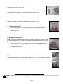
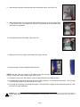
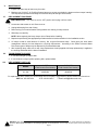
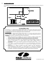
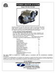
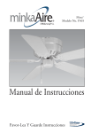
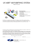
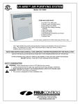
UV-AIRE™ AIR PURIFYING SYSTEM
Model: UV-18X
ITEMS INCLUDED IN KIT:
1-UV-Aire™ power unit
4-Sheet metal mounting screws
2-Angled mounting brackets
2-Flat mounting brackets
1-Duct board mounting bracket
2-Ultra Violet lamps
1-Instruction Sheet
2-Wing nuts
Caution Labels
Gasket
UV-C light inhibits the growth and reproduction of germs and bacteria that circulate through a
homes’ heating and air conditioning system. The treatment is a safe, silent, and proven way
to make your home a healthier place to live.
READ THESE INSTRUCTIONS CAREFULLY AND COMPLETELY BEFORE PROCEEDING WITH THE INSTALLATION
LEAVE THE INSTALLATION INSTRUCTIONS WITH THE OWNER/OPERATOR OF THE DEVICE
AFTER OPENING THE CARTON, UNPACK AND INSPECT THE UNIT AND LAMP FOR DAMAGE.
DO NOT INSTALL THIS UNIT IF ANY DAMAGE IS NOTICEABLE.
SAFETY CONSIDERATIONS
WARNING: Never expose eyes or skin to UVC light from any source.
• Looking directly at the UVC light may cause permanent eye damage or blindness.
• Never operate the UV-Aire™ Air Purifying System out of the plenum.
• Designed for a closed duct system. Do not mount near a return air opening
• All duct openings in direct line of site of the UV light must be sealed with duct tape or equivalent sealing
methods.
WARNING: UV light will break down plastic materials not rated for UV exposure:
(Examples: wire insulation, flex duct, drain pans and humidifiers)
• The unit must be mounted at least 30” from the above stated type of materials.
• If it is necessary to mount the unit in direct line of site of these types of materials, they must be shielded
with aluminum foil, aluminum foil tape, or sheet metal.
WARNING: DO NOT mount this unit outdoors.
• This product is designed for indoor installation only (i.e. attics, crawl spaces, basements, etc.).
I.
INDICATION FOR USE
II.
This product is not sold as a medical device and is not for the purpose of diagnosis of any disease or condition nor for
use in the mitigation, treatment, or prevention of any disease or condition.
GENERAL INFORMATION
There are different size units available, depending on the square footage of your home.
determining your homes needs.
See chart below for
Model
Minimum
Duct
Width
Volts
Amps
Hz
Watts
Max Air
Temp °F
Lamp Intensity at 1
meter
Recommended
Max Sq. Feet
UV-18X
14
120
1.0
60
60
190°
2@73 μW/cm2
4000
WARNING: Before installing or servicing a humidifier, air filter, heat system, or this unit, etc., always turn all power
OFF and have units unplugged. Electrical shock can cause personal injury or death. Never expose eyes or skin to
direct UVC light from any source.
WARNING: To prevent water damage or electric shock, do not mount unit under a humidifier.
WARNING: Designed for a closed duct system. Do not mount near a return air opening.
WARNING: This product is designed for indoor installation only (i.e. attics, crawl spaces, basements, etc.). For
use on gas fired, oil fired, electric and split system heat pump forced air systems*. This product is NOT designed
to be mounted outside on gas fired or heat pump packaged units**.
*Split system heat pumps are systems where the air handler and the air conditioning compressor are separate units.
**Packaged units are systems where the air handler and the air conditioning compressor are built together and are installed outside of the building
III.
INSTALLATION
1. Locate a suitable location for the unit downstream from the ‘A’ coil in the supply plenum or in the return plenum;
preferably downstream from the air filter. For optimum “cleaning” effect on the ‘A’ coil, mount the unit in the supply
plenum as close as possible to the ‘A’ coil. (See Figure 1)
Figure 1
WARNING: Never expose eyes or skin to UVC light from any source. Looking directly at the UVC light may cause permanent eye damage or
blindness. Never operate the UV-Aire™ Air Purifying System out of the plenum. Avoid touching the glass portion of the lamp with your
hands.
Page 2
2. Determine the type of duct you have.
(For flex duct applications, refer to Figure 21 on page 8)
IF YOU HAVE METAL DUCT:
a. Apply supplied wet and stick mounting template to air duct
in either a vertical or horizontal position as shown in Figure
2.
b. Drill 1/8” diameter mounting holes at positions indicated on
template.
c.
Cut out rectangular hole on template using a pair of tin
snips or jigsaw. (See Figure 2) Remove template.
IF YOU HAVE DUCT BOARD:
a. Mount the supplied metal mounting plate onto the duct with
duct tape in either a vertical or horizontal position as shown
in Figure 2. (See Figure 3)
Figure 2
b. Bend tabs outward as shown in figure 4.
c.
Using a knife or blade, cut out a rectangle opening in the duct using the mounting plate as a template. (See
Figure 5)
d. Remove the cut piece of duct. (See Figure 7)
e. Bend both tabs down and through duct at first bend point. (See Figures 8 &9)
f.
Bend both tabs at the second bend point up or down to pinch the duct material and grip the duct material.
(See Figures 10 & 11
g. Using a screwdriver or pointed object, locate mounting holes by poking holes through the duct tape. (See
Figure 12)
Figure 3
Figure 5
Figure 4
Figure 9
Figure 10
Figure 7
Figure 11
Figure 12
Figure 8
WARNING: Never expose eyes or skin to UVC light from any source. Looking directly at the UVC light may cause permanent eye damage or
blindness. Never operate the UV-Aire™ Air Purifying System out of the plenum. Avoid touching the glass portion of the lamp with your
hands.
Page 3
3. Remove base unit and cover from box.
4. Apply supplied “Duct Seal Kit” according to instructions included in kit.
(See Figure 12)
Figure 12
5. Determine whether to use flat or angled bracket. (Refer to UV-Aire
Configurations in Section III for aid in this decision)
a. Flat Bracket Installation
i.
ii.
Remove the two hex nuts and flat bracket from included bagged hardware.
Install the flat bracket and secure to the unit base with the hex nuts provided.
(See Figure 13)
Figure 13
b. Angled Bracket Installation
NOTE: For angled bracket mounting, refer to specifications outlined by Diagrams A & B
for mounting distances in the “Angled Lamp Mounting Bracket Specifications” in section
III.
i.
ii.
Remove the two hex nuts and angled bracket from included bagged hardware.
Install the angled bracket and secure to the unit base with the hex nuts
provided. (See Figure 14)
NOTE: Be sure to note location of lamp hole in bracket relative to unit base.
Figure 14
6. Mount the unit base to the duct using the four mounting screws provided. (See Figure
15)
7. Remove tag and alcohol from lamp. Wipe off lamp being sure not to touch lamp with bare
hands. The oils in your hands may cause the lamp to prematurely expire.
Figure 15
WARNING: Never expose eyes or skin to UVC light from any source. Looking directly at the UVC light may cause permanent eye damage or
blindness. Never operate the UV-Aire™ Air Purifying System out of the plenum. Avoid touching the glass portion of the lamp with your
hands.
Page 4
8. Insert lamp through hole until lamp cannot be inserted any further. (See Figure 16)
Figure 16
9. Swing swivel bracket over end of lamp. Hand-tighten the wing nut on stud. (See Figure
17) Be careful not to over tighten the wing nut. The porcelain at the lamp base may
crack when over tightened.
Figure 17
10. Plug ballast plug into end of lamp. (See Figure 18)
Figure 18
11. Replace cover on unit. Tighten side screws. (See Figure 19 & 20)
12. Plug the power cord into a standard electrical outlet.
NOTE: Seal the joints and seams of the plenum near the mounting
location to reduce any direct viewing of light. (See Figure 1)
Figure 19
Figure 20
13. Flip switch on box to the ‘ON’ position. (Light on switch should be on indicating power.)
14. Look through view port in the box cover to be sure lamp is working. You should see a blue glow. (The view port
is covered with a plastic lens that blocks the UVC rays.)
15. If the lamp is not glowing, follow steps 8-14 again. If lamp still does not glow, contact technical support at 1-252522-3031 for further assistance.
WARNING: Never expose eyes or skin to UVC light from any source. Looking directly at the UVC light may cause permanent eye damage or
blindness. Never operate the UV-Aire™ Air Purifying System out of the plenum. Avoid touching the glass portion of the lamp with your
hands.
Page 5
IV.
BULB MOUNTING BRACKET SELECTION AND INSTALLATION
The UV-AIRETM units come with an angled mounting bracket and flat mounting bracket to position the bulb either
straight or at an angle. Choose one or the other bracket method best suited for your needs. Refer to the
configurations chart below when making your selection.
UV-Aire™ Configurations
Patent Pending 45°
Installation
Double Lamp
(Angled Bracket)
Angle option allows longer lamps to fit
in smaller ducts.
(16” Duct)
Standard 90°
Installation
Double Lamp
(Flat Bracket)
(20” Duct)
ANGLED LAMP MOUNTING BRACKET SPECIFICATIONS
Use the specifications below to determine allowable clearances for proper mounting of the UV-Aire™ unit on the duct.
Diagram A
LAMP CENTER LINE FOR ANGLED
DOUBLE LAMP INSTALLATION
Min Duct
“A” Dimension
Unit
Size
(inches)
(inches)
Center on Duct
UV-18X
14x18
Housing
Diagram B
LAMP OFFSET DIMENSIONS
Unit
A
B
UV-18X
13-1/2
10-5/16
WARNING: Never expose eyes or skin to UVC light from any source. Looking directly at the UVC light may cause permanent eye damage or
blindness. Never operate the UV-Aire™ Air Purifying System out of the plenum. Avoid touching the glass portion of the lamp with your
hands.
Page 6
V.
MAINTENANCE
1. Inspect and clean lamp at least every 6 months.
2. Replace your UV-Aire™ Air Purifying System lamp once a year to maintain the lamps maximum output intensity.
The lamp should operate continuously for maximum lamp life and light effectiveness.
VI.
REPLACEMENT PROCEDURE
VERY IMPORTANT: Turn switch on unit to ‘OFF’ position and unplug unit from outlet.
1. Loosen two side screws on unit. Remove cover.
2. Unplug ballast plug from end of lamp.
3. Remove wing nut on swivel bracket. Swing bracket out clearing for lamp removal.
4. Slide lamp out carefully.
NOTE: When replacing the lamp, always wipe off lamp before installing.
5. Replace lamp following the appropriate procedure based on bracket selection in the installation section.
6. UV lamps contain a small amount of mercury, like a typical fluorescent lamp. Check with your local waste
management authority for local disposal or recycling requirements. According to the EPA’s Universal Waste
Rule, these types of lamps may be disposed of into household waste
7. After replacing lamp, make sure a new Lamp Replacement Label (supplied with lamp replacement) is applied to
the housing and dated with the date of installation.
VII.
TROUBLESHOOTING GUIDE
1. If unit does not light up replace bulb.
2. If unit still does not light up after replacing bulb, replace ballast.
VIII.
REPLACEMENT PARTS LIST
MODEL
LAMP
(Field Controls Part Number)
BALLAST
(Field Controls Part Number)
UV-18X
46365402
46365503
For replacement parts, contact your local heating service company. Any questions, please contact Field Controls at:
Phone: 252-522-3031
Fax: 252-522-0214
Email: [email protected]
WARNING: Never expose eyes or skin to UVC light from any source. Looking directly at the UVC light may cause permanent eye damage or
blindness. Never operate the UV-Aire™ Air Purifying System out of the plenum. Avoid touching the glass portion of the lamp with your
hands.
Page 7
IX.
FLEX DUCT INSTALLATION
For installations on duct systems with a metallic main duct and flex duct branches, follow the instructions in figure 21
below.
Figure 21
Limited Warranty
Field Controls, L.L.C. warrants that the following Field Controls, L.L.C. products sold hereunder, shall be
free from defects in material and workmanship under normal use for eighteen (18) months from date of
manufacturing by the consumer excepting the provisions numbered below.
UV-LAMPS/BULBS
Field Controls, L.L.C. warrants that the following Field Controls, L.L.C. products sold hereunder, shall be
free from defects in material and workmanship under normal use for ninety (90) days from date of
installation by the consumer excepting the provisions numbered below.
Provisions:
1. Field Controls shall have no obligation in the event the customer is unable to provide receipt
showing the date the customer purchased the product(s) or accurate date code information.
2. The product must be properly installed, maintained and operated under normal conditions.
3. Field Controls shall not be liable for any consequential and incidental damages, resulting from
failure of a Field Controls, L.L.C. product, failure to deliver, delay in delivery, delivery in
nonconforming condition, or for any breech of contract or duty between Field Controls, L.L.C. and
the customer.
4. Field Controls, L.L.C. products are often intended for use in specific applications. Field Controls,
L.L.C. makes no warranty if a Field Controls, L.L.C. product is used in applications other than
intended.
5. Field Controls, L.L.C. makes no warranty of any kind in regard to any other manufacturer’s
products distributed by Field Controls, L.L.C. Field Controls, L.L.C. will pass on all warranties
made by the manufacturer and where possible, will expedite the claim on behalf of the customer,
but ultimately, responsibility for disposition of the warranty claim lies with the manufacturer.
The health aspects associated with the use of these products and their ability to aid in disinfecting of environmental air have not been investigated by UL.
Page 8
P/N 46453300 Rev C 04/05