1
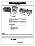
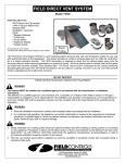
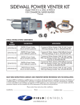
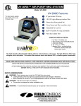
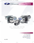
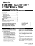
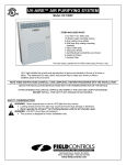
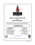
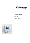
POWER VENTER SYSTEM
Model: PVO-300, PVO-600
Included is one ETL and cETL listed Power Venter to be used primarily with a
single 120VAC controlled oil fired furnace, boiler, or water heater. The PVO
may be used to common vent multiple appliances with the addition of a Control
Kit. Please consult Field Control’s Technical Support for other options.
TYPICAL VENTING SYSTEM COMPONENTS
One PVO Series Power Venter with pre-wired controls; adjustable post
purge relay timer, adjustable draft proving switch, direct access terminal
blocks, and piping tee for multiple appliance systems.
• Side Wall Vent Hood (Not included)
• Spill Switches (Not included)
• CK-Series Control Kit for multiple appliance venting (Not Included)
CONTENTS
Unit Specifications
System Operation
Power Venter Sizing
Installation Safety Instructions
Installation of Power Venter
General Wiring Instructions
Airflow Adjustments
Pressure Switch Adjustments
Post Purge Timer Adjustments
Multiple Appliance Systems
General Installation Inspection
Maintenance
Replacement Parts List
Venting System Operational Information
Installation Information
PAGE
2
2
3
4
5
5-6
7
7
7
7
8
8
9
10
10
This device MUST be installed by a qualified agency in accordance with the manufacturers installation
instructions.
The definition of a qualified agency is: any individual, firm, corporation or company which either in person or through a representative is
engaged in, and is responsible for, the installation and operation of gas appliances, who is experienced in such work, familiar with all
the precautions required, and has complied with the requirements of the authority having jurisdiction.
DO NOT DESTROY
THESE INSTRUCTIONS MUST REMAIN WITH EQUIPMENT
2630 Airport Road · Kinston, NC 28504
Phone: 252-522-3031· Fax: 252-522-0214
www.fieldcontrols.com
UNIT SPECIFICATIONS (See Table 1 and Figure 1)
Table 1
UNIT DIMENSIONS (INCHES)
MODEL
“H”
“W”
“D”
I/O*
PVO-300
7.50
9.25
7.00
4/4
PVO-600
8.75
9.75
8.50
4/4
*
Inlet and outlet diameter.
ELECTRICAL RATINGS
MODEL
VAC
Hz
RPM
WATT
AMP
TP**
PVO-300
120
60
3000
145
2.1
YES
PVO-600
120
60
3000
167
1.5
YES
Figure 1
**
Thermally protected motor.
SIDEWALL VENT HOODS (Model SWH-1)
Sidewall vent hoods are available in the following sizes. The vent hood should be chosen that matches the outlet size of
the Power Venter. (See Figure 2) NOTE: When using different sizes consider reducers and specific size pipe when
determining equivalent length of vent pipe.
SWH-1-3 - 3 inch
SWH-1-4 - 4 inch
SWH-1-5 - 5 inch
SWH-1-6 - 6 inch
SWH-1-8 - 8 inch
Figure 2
CONTROL KITS
The following Control Kits can be used to common vent multiple appliances with on PVO unit:
CK-61:
For operation with all 120VAC oil-fired systems. Includes draft proving switch, adjustable electronic
post purge timer, RJR isolation relay, and WMO-1 secondary safety switch.
CK-62:
Same as CK-61, except has thermally activated post purge.
CK-63:
For operation with all 120VAC oil-fired systems. Includes draft proving switch, adjustable electronic
post purge timer, and WMO-1 secondary safety switch.
SYSTEM OPERATION
1. The thermostat (wall thermostat, or aquastat) calls for heat and energizes a relay which activates the power venter.
After the venter motor has come up to speed, the pressure switch closes. This completes the circuit to the burner and
allows the burner to fire.
2. After the heating requirement has been satisfied, the thermostat circuit will open and de-activate the burner and power
venter circuit.
3. The power venter continues to operate for a period of time after the burner has shut off to purge remaining flue gases.
Page 2
POWER VENTER SIZING
In order to choose the correct size power venter for a particular installation, the total input firing rate and total equivalent
length of vent pipe to be used must be known. Refer to Table 2 to determine the maximum allowable equivalent feet of
pipe for each model used with the pipe diameters shown. When venting multiple appliances, add the input of each
appliance to determine the total input. Always choose a power venter that is capable of handling more than the system
requires. The choke plate can be adjusted to compensate for the difference.
Table 2
MAXIMUM EQUIVALENT HORIZONTAL PIPE LENGTH (FEET)
VENTER MODEL NO. AND VENT PIPE DIAMETER
BTU/HR INPUT
PVO-300
PVO-600
4”
5”
6”
5”
6“
8”
0.75
287
---
---
---
---
---
1.00
150
257
346
428
---
---
1.50
75
120
172
212
---
---
2.25
---
51
70
86
143
211
3.00
---
---
---
46
74
116
3.75
---
---
---
---
51
84
4.00
---
---
---
---
---
77
PROCEDURE FOR CALCULATING TOTAL EQUIVALENT PIPE LENGTH IN FEET
1. Calculate the total equivalent feet for each type of fitting used in the venting system from the following chart.
2. Calculate the total amount of feet for the straight lengths of vent pipe.
3. Add the equivalent feet for the fittings with the total amount of feet of straight lengths.
Table 3
EQUIVALENT LENGTH (FEET) OF VENT PIPE FOR VENT PIPE FITTINGS
VENT PIPE FITTINGS
VENT PIPE DIAMETER
3”
4”
5”
6”
7”
8”
9”
10”
TEE
19
25
31
38
44
50
56
63
90° ELBOW
5
7
9
11
12
14
16
18
45° ELBOW
3
4
4
5
6
7
8
9
1/4
8
11
14
17
19
22
25
28
1/2
5
7
8
10
12
13
15
17
3/4
2
3
3
4
4
5
6
6
REDUCER
(d/D)*
*
Reducer or increaser ratio (d/D) small diameter divided by the larger diameter. (See Figure 3)
Example: 4" to 8" reducer, the reducer ratio is d/D = 4/8 = 1/2. To estimate the equivalent foot
length for the fitting, use the smaller pipe diameter for the equivalent length figure. Example:
4" to 8" reducer; the reducer ratio is 1/2 and the smaller pipe diameter is 4". So, from the chart,
the equivalent feet would be 7 feet.
Example: System Pipe Size = 4"
Step 1
2 – 90° Elbows (4") = 14 Ft.
Step 2
10 - 2 Ft. Lengths of 4" Pipe = 20 Ft.
Step 3
Total Equivalent Feet = 14 Ft. + 20 Ft. = 34 Ft.
Page 3
Figure 3
Diagram A
INSTALLATION SAFETY INSTRUCTIONS
CAUTION: This device must be installed by a qualified installer in accordance with the manufacturer's installation
instructions. Appliances should have a minimum of 75% combustion efficiency or have a maximum measured flue gas
temperature of 550°F at the inlet of the venter.
1. The power venting system must be installed by a qualified installer. "Qualified Installer" shall mean an individual who
has been properly trained or a licensed installer. The installer must write or imprint his name, phone number and date
of installation on the installation tag. The tag should be attached to the power venter unit. Recording burner and
venting system initial operational information is recommended as a guide for service or burner tune-up. Enter this on
the back page of this manual.
2. Safety inspection of a venting system should be performed before and after installing a power venting system on an
existing or new appliance. Procedures to follow are those recommended by the National Fuel Gas Code,
A.N.S.I.Z223.1 or refer to the "General Installation Inspection" section of this manual.
3. Plan the vent system layout before installation to avoid the possibility of accidental contact with concealed wiring or
plumbing inside walls.
4. Single wall vent pipe may be used to join an appliance to the venting system, but if proper clearances cannot be
maintained from combustible materials, Class B Vent Pipe should be used for gas appliances. Refer to national or
local codes for guidelines.
5. Disconnect power supply before making wiring connections to prevent electrical shock and equipment damage.
6. This equipment is designed to overcome minor negative pressure conditions. To ensure extreme negative pressure
does not exist, follow the "General Installation Inspection" section of this manual.
7. Heating appliances equipped with draft hoods, such as boilers or furnaces, LP and natural gas appliances SHOULD
have a secondary spillage switch installed. On appliances without draft hoods, it is recommended that the secondary
safety switch GSK-3 be installed into the system. Gas-fired 30 millivolt power systems MUST be equipped with a
spillage switch.
8. Air flow adjustment MUST be made to ensure appliance efficiency. This should be done at the appliance exhaust
outlet with a velocity meter, draft gauge or by the "match test procedure". The match test is in accordance with
National Fuel Gas Code A.N.S.I.Z223.1, Section 8.6.
9. On heating appliances not equipped with a draft hood, a barometric draft control MUST be installed to regulate proper
air flow and fluctuations in the system's air flow during operation. Fluctuations can come from wind loads on the outlet
of the venter, house depressurization during windy days and the different house ventilation requirements between
summer and winter operation. Use a Field Controls Type MG-1 Barometric Draft Control. Gas-fired draft induced
systems should have a single-acting or double-acting barometric draft control installed.
Page 4
INSTALLATION OF POWER VENTER
CAUTION: Failure to install, maintain and/or operate the power venting system in accordance with manufacturer's
instructions will result in conditions which may produce bodily injury and/or property damage.
1. Remove power venter from box and inspect unit for damage. If the carton has been crushed or mutilated, check unit
very carefully for damage. Rotate venter wheel to insure that the motor and venter wheel rotate freely. DO NOT install
if any damage is apparent. Refer to unit sizing chart to check proper venting sizing.
2. Location of the termination of the venting system should be installed in accordance with the National Fuel Gas Code,
A.N.S.I.Z233.1, manufacturer's recommendations, and/or local codes which are applicable. See the following
requirements or refer to Diagram A for typical locations.
a. The exit termination of mechanical draft systems shall not be less than 7' above grade when located adjacent to
public walkways.
b. A venting system shall terminate at least 3' above any forced air inlet located within 10'.
c. The venting system of other than a direct vent appliance shall terminate at least 4' below, 4' horizontally from, or 1'
above any door, window, or gravity air inlet into the building. When venting oil fired equipment with a Field
Control’s CAS-2 series Airboot® kit, the intake air hood can be mounted within 12 inches of the power venter
exhaust.
d. The vent termination of a direct vent appliance with an input of 50,000 BTU/Hr or less, shall be located at least 9"
from any opening through which vented gases could enter the building. With an input over 50,000 BTU/Hr, a 12"
termination clearance shall be required.
e. The vent termination point shall not be installed closer than 3' from an inside corner of an L-shaped structure.
f. The vent termination should not be mounted directly above or within 3' horizontally from an oil tank vent or gas
meter.
g. The bottom of the vent terminal shall be located at least 12" above finished grade.
CONNECTING VENTER TO APPLIANCE
The venting system should be installed and supported in accordance with the National Fuel Gas Code ANSIZ223.1, or in
accordance with any local codes. A vent pipe connector shall be supported for the design and weight of the material
employed, to maintain clearances, prevent physical damage and separation of joints. A vent pipe increaser or reducer
may be required for connecting the venter to the vent system. Smaller vent pipe sizes than a chimney-vented system
may be used for the vent system.
Route the vent pipe from the appliance to the venter using a minimum number of elbows as possible. The horizontal
section of the vent pipe should have a slight upward slope from the appliance to the venter. For clearances to
combustible materials, multiple appliance venting and other installation requirements, refer to the National Fuel Gas Code
ANSIZ223.1, and/or any applicable local codes or appliance manufacturer’s installation instructions.
GENERAL WIRING INSTRUCTIONS
CAUTION: Disconnect electrical power before wiring power venter!
The PVO is designed to be used with appliances with 120VAC control systems. Wire the venter motor and controls in
accordance with the National Electric Code, and/or applicable local codes. UNIT MUST BE GROUNDED. Check ground
circuit to make certain that the unit has been properly grounded. The wiring should be protected by an over-current circuit
device rated at 15 amperes. CAUTION MUST be taken to ensure that the wiring does not come in contact with any heat
source. All line voltage and safety control circuits, between the venter and appliance, MUST be wired in accordance with
the National Electrical Code for Class 1 wiring, or equivalent methods. Refer to wiring diagrams B & C for typical wiring.
For other wiring diagrams, please contact Field Control’s Technical Support.
NOTE: When applying power to the PVO for the first time, the venter motor may, or may not, run for up to 10 minutes.
This is normal, and will not affect the operation of the system.
Page 5
Diagram B
Diagram C
Page 6
MULTIPLE APPLIANCE SYSTEMS
When using one PVO power venter to common vent more than one
appliance, a Control Kit is required for each additional appliance.
1. Connect the negative pressure port of each air pressure fan proving
switch on all Control Kits being used to the provided tee mounted on
the PVO. (See Figure 4)
2. Remove the cap from the branch of the tee and use the ferrule and
compression nut provided in the small envelope with the PVO to attach
the connecting tube.
3. Refer to the instruction sheet included with each Control Kit for specific
instructions for that kit, including wiring diagrams.
ADJUSTMENTS
AIR FLOW ADJUSTMENT
NOTE: Before installing, refer to the General Installation Inspection to
check for negative pressure problems in the building.
1. To adjust the power venter air flow, open the choke plate ½ to ¾ of the
way open. (See Figure 5) Follow the appliance manufacturer’s
procedures for starting the heating appliance.
2. Adjust the thermostat to call for “Heat”. After the system has operated
for several minutes to stabilize flue gas temperatures, use a draft
gauge, velocity meter, or match test procedure to check for negative
draft or up-draft at the heating appliance outlet or air flow into the draft
hood.
3. Adjust the inlet choke damper on the power venter in or out to obtain
the minimum air flow required to maintain draft. Then increase air flow
slightly (10% over minimum air flow rate) to ensure proper venting.
For power burners, adjust draft to proper over-fired draft.
If using a barometric draft control, use the draft control to fine tune the
system draft.
4. If proper draft has been established, secure the choke plate by
tightening the screws on the inlet collar.
5. Shut off thermostat and check for residual heat spilling from the draft
hood or draft control. If this occurs, increase the post purge time on
the timer.
NOTE: After proper venting has been established, it is recommended
that a combustion test and a smoke test be performed to ensure
maximum burner efficiency. Oil burner air adjustments should be set at a
zero to a trace smoke at the highest or recommended CO2% setting set
by heating equipment manufacturer.
PRESSURE SWITCH ADJUSTMENT
1. With the venter air flow set and the appliance operating at the best operating
efficiency, adjust the pressure switch by rotating the adjustment screw
clockwise until the burner shuts off.
2. Rotate the adjustment screw counterclockwise until the burner fires.
3. Rotate the adjustment screw an additional ¼ turn counterclockwise to insure
proper switch setting. (See Figure 6)
POST PURGE TIMER ADJUSTMENT
To adjust the post purge time, refer to Figures 7 & 8.
For timer that looks like Figure 7: Rotate the timer adjustment on
timer clockwise to increase the operation time. To decrease
operation time, rotate the timer adjustment counterclockwise.
For timer that looks like Figure 8: Rotate the timer adjustment on
timer counterclockwise to increase the operation time. To decrease
operation time, rotate the timer adjustment clockwise.
*Typical post purge time should be between 3 to 5 min.
Page 7
Figure 4
Figure 5
Figure 6
Figure 7
the
the
the
the
Figure 8
GENERAL INSTALLATION INSPECTION
Follow recommended procedures for safety inspection of a heating appliance in accordance with the National Fuel Gas
Code A.N.S.I. Z223.1. The following procedure will help in evaluation of the venting system. It is intended as a guide to
aid in determining that the appliance is properly installed and is in a safe condition for continuous use. This is a
generalized procedure which cannot anticipate all situations. Accordingly, in some cases deviation from this procedure
may be necessary to determine safe operation of the equipment. If it is determined that a condition which could result in
unsafe operation exists, the appliance should be shut off and the owner advised of the unsafe conditions. Corrections
must be made prior to allowing continuous operation. The following steps should be taken in making a safety inspection.
1. Visually inspect the venting system for proper size and determine that there is no blockage, restriction, leakage,
corrosion, or other deficiencies which could cause unsafe operation.
2. To the extent possible, close all building doors, windows, and all doors to the room in which the heating appliance is
located. Turn on clothes dryers and any exhaust fans so that they operate at maximum speed. Do not operate a
summer exhaust fan. Also close all fireplace dampers. If after completing steps 3 through 7 it is believed that sufficient
combustion air is not available, refer to the National Fuel Gas Code A.N.S.I. Z223.1 or any local codes for proper
guidelines.
3. Place the appliance being inspected into operation. Follow the lighting instructions and adjust the thermostat so that
the heating appliance will operate continuously.
4. Determine that the burner is operating properly and that the main burner ignition functions satisfactorily, by
interrupting the electrical power of the appliance in any safely convenient manner. Test the burner safety device to
determine if it is operating properly by extinguishing the pilot or disconnecting the flame safety circuit.
5. Visually determine that the main burner is burning properly, i.e. no floating, lifting, or flashbacks. Adjust the primary air
shutter as required by the appliance manufacturer. If the appliance is equipped with high and low flame control or
flame modulation, check for proper main burner operation at both flame levels.
6. If appliances are equipped with high and low flame control or flame modulation, check for proper main burner
operation at low flame.
7. Test for exhaust gas spillage at the draft hood or the barometric draft control after approximately 5 minutes of main
burner operation. Use a draft meter or flame or smoke from match, candle or cigarette. If spillage occurs, adequate
air is not available. Shut off heating appliance thermostat and check for spillage around the draft hood, barometric
draft control or burner inlet air location after power venter has stopped operation. If a flow reversal is noticed, house
depressurization is occurring and make up air is required. For oil-fired systems, this may be noticed by oil fume smell
after post purge cycle.
8. Turn on all fuel burning appliances within the same room so that they operate at their maximum capacity. Then repeat
Steps 5 and 7.
9. Return all doors, windows, exhaust fans, fireplace dampers, and any other fuel burning appliances to their previous
condition.
MAINTENANCE
1. Motor: Inspect the motor once a year - motor should rotate freely. To prolong the life of the PVO-600 motor, it must
be lubricated with six drops of SWG Superlube, Part #46226200, annually. The PVO-300 has sealed ball bearings,
and therefore does not need to be oiled.
2. Blower Wheel: Inspect the blower wheel annually to clear any soot, ash or coating which inhibits either rotation or air
flow. Remove all foreign materials before operating.
3. Vent System: Inspect all vent connections annually for looseness, for evidence of corrosion and for flue gas leakage.
Replace, seal, or tighten pipe connections if necessary. Check the power venter choke plate to insure it is secured in
place. Check the barometric draft control, if installed, to insure the gate swings freely.
4. System Safety Devices: With the heating system operating disconnect the pressure sensing tube from the pressure
switch on the venter. This should stop the burner operation. Re-connecting the tube will relight the burner.
Page 8
PV SERIES POWER VENTER: VERTICAL VENTING OPTION
Diagram D illustrates correct and incorrect installation of PV series venter in vertical vent configuration (except PVE1200). The correct installation maintains the required vertical position of the pressure switch; the incorrect installation
does not. The following conditions must also be observed:
• Natural gas, lp gas or #2 fuel oil appliance rated at 75% or greater non-condensing type of appliance.
• Maximum input temperature at power venter: 575°F
Diagram D
Page 9
REPLACEMENT PARTS LIST
The following items are available for replacement, if necessary.
REPLACEMENT PARTS LIST
DESCRIPTION
PVO-300
PVO-600
Motor
46032000
46083300
Blower Wheel
46033400
46089400
Post Purge Relay Timer
46144700
4614470
Pressure Switch
46311000
46311000
VENTING SYSTEM OPERATIONAL INFORMATION
Date:
Oil Burner Nozzle Size
Oil Burner Operating Pressure
Pump Operating Vacuum Pressure
Smoke Number
Over-Fire Draft
Equipment Outlet Flue Gas Temperature
CO2 measurement
INSTALLATION INFORMATION
PVOMODEL NO.:____________________________________________________________
INSTALLER'S NAME:_____________________________________________________
INSTALLER'S COMPANY: _________________________________________________
INSTALLER'S PHONE NO.: ________________________________________________
DATE OF INSTALLATION:_________________________________________________
Page 10
NOTES
Page 11
Page 12
P/N 46311800 Rev E 11/07