1
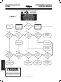
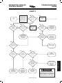
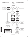
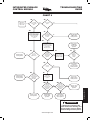
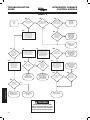
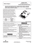
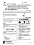
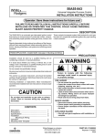
INTEGRATED FURNACE
CONTROL MODULE
TROUBLESHOOTING
GUIDE
50A55 INTEGRATED FURNACE CONTROL MODULE
Qualified Serviceman’s Troubleshooting Guide
TROUBLESHOOTING PROCEDURE
If the light on the module is on continuously, the fault is likely to be internal to the
module. To make sure, interrupt line or 24 volt thermostat power for a few seconds
and then restore. If internal fault is indicated again, and flame sensor is not shorted
to ground, replace control. A flashing light indicates the problem is most likely in the
external components or wiring. Proceed as follows:
! WARNING
Turn power off before any troubleshooting or servicing begins.
! WARNING
Failure to read and follow all
instructions carefully before installing or operating this control,
could cause personal injury and/
or property damage.
Line voltage (120 VAC) could be present on the surface of the ignitor, if the system is not correctly wired. Such voltage can cause serious injury or death.
The following steps must be performed first before any troubleshooting begins.
1)Disconnect electric power to system at main fuse or circuit breaker.
2)Visually inspect equipment for apparent damage. Check wiring for loose
connections.
3)Check for proper grounding and reversed polarity.
A. Check continuity for C terminal on module to electrical service ground and
connection at the furnace junction box. If ground connection is open, check
module ground connection and the electrical service ground connection.
Repair and retest.
B. Re-connect electric power to system.
C. Check for voltage between the line neutral terminal and furnace ground. If
voltage exists, the main power supply lines are improperly connected to the
furnace (REVERSED POLARITY). Again disconnect electric power to system;
then reverse incoming supply leads to furnace. Repeat step.
D. Recheck system for proper operation.
If neither apparent damage, loose connection nor reversed polarity is the problem,
proceed to troubleshooting chart or fault index chart that is suggested by the actual
condition.
NOTE: This troubleshooting guide is not for 50A55-4XX modules found on Trane
equipment or 50A55-1XX modules found on Lennox equipment.
FAULT INDEX CHART
TECHNICAL HELP
No manual fan............................................. 1A - 1K
Power supply and voltage........................... 1C - 1G
No fan at cooling speed............................... 2A - 2L
No induced draft motor................................ 3A - 3H
LED flashing 2X without inducer................. 3
E
LED flashing 3X with inducer...................... 3I - 3O
Ignitor does not glow................................... 4A - 4D
Burner does not stay lit................................ 4E - 4N
Gas supply problem.................................... 4F - 4K
No outlet pressure....................................... 4H - 4J
Gas valve does not energize....................... 4L - 4N
Flame sensor fault....................................... 5A - 5P
Burner ground............................................. 5K
Polarity check.............................................. 5L - 5M
Ignitor stays on after burner ignition............ 5B - 5C
www.white-rodgers.com
189
TROUBLESHOOTING
GUIDE
INTEGRATED FURNACE
CONTROL MODULE
CHART 1
1A
Place
thermostat
fan switch in
the ON
position.
Indoor Blower
Check
1B
Does indoor
blower run at
HEAT speed?
YES
Return fan
switch to
AUTO position.
NO
1C
1D
Does LED
flash 1 time
when disconnect
is turned
ON?
1E
Is 24V
present at
control
terminals
R & C?
YES
NO
1F
Is 24V
present at
control
terminals
G & C?
YES
NO
YES
Is 120V
present at
control terminals
COOL & CIR
NEUTRAL?
NO
YES
Indoor blower
fault. Repair or
replace. Check
operation.
NO
Replace control.
Check operation.
Replace control.
Check operation.
Repair wiring
from control to
thermostat. Check
operation.
1G
1H
Is 120V
present across
control terminals
LINE & LINE
NEUTRAL?
YES
Is 120V
present at
control terminals
XFMR & XFMR
NEUTRAL?
NO
TECHNICAL HELP
1I
NO
Correct 120V
power supply. Check
operation.
YES
1J
Is 120V
present across
primary of control
transformer?
YES
NO
Repair wiring to
transformer. Check
operation.
! WARNING
If diagnostic indicator (LED)
shows continuous flashing, turn
off gas supply at source before
disconnecting electrical power!
190
www.white-rodgers.com
1K
Is 24V
present across
secondary of
transformer?
NO
Replace
transformer. Check
operation.
YES
Is 24V
present
across 12-pin
connector pins TH
& TR on the
control?
NO
Repair wiring
and/or plug
connection. Check
operation.
YES
INTEGRATED FURNACE
CONTROL MODULE
TROUBLESHOOTING
GUIDE
CHART 2
2A
Place thermostat
system switch in
cooling mode and fan
switch in AUTO
position. Lower
temperature selection
lever to call for a
cooling cycle. R & Y
contacts close.
Cooling
Cycle
Check
2B
Does indoor
blower energize
at cooling
fan speed?
YES
Return thermostat
to desired
setting.
NO
2C
2E
2D
Does
indoor blower
energize at
heating fan
speed?
YES
Is
thermostat terminal
YES
Y connected to furnace
terminal Y?
NO
2F
Does
indoor blower
energize at
cooling fan
speed?
With door
switch closed,
jumper control
terminals
R & Y.
NO
YES
Repair low
voltage wiring to
thermostat. Check
operation.
NO
2H
Is 120V
present at
control terminals
COOL & CIR
NEUTRAL?
Correct wiring
from thermostat
terminal Y to Y on
furnace. Check
operation.
YES
Indoor blower
fault. Repair or
replace motor.
Check operation.
NO
2G
Is 24V
present across
control terminals
Y & C?
YES
Replace control.
Check operation.
NO
2I
2J
Is 24V
present at
control terminals
R & C?
YES
NO
2K
Is 24V
present at
control terminals
G & C?
NO
Is 120V present
at primary of
transformer?
YES
YES
Replace
transformer.
Check operation.
NO
2L
YES
Repair wiring
between control and
transformer
primary. Check
operation.
TECHNICAL HELP
Is 120V
present at
control terminals
LINE & LINE
NEUTRAL?
NO
Repair low
voltage wiring to
thermostat.
Check operation.
Repair low
voltage wiring
from transformer to
control. Check
operation.
Correct 120V
power supply to
control. Check
operation.
www.white-rodgers.com
! WARNING
If diagnostic indicator (LED)
shows continuous flashing, turn
off gas supply at source before
disconnecting electrical power!
191
TROUBLESHOOTING
GUIDE
INTEGRATED FURNACE
CONTROL MODULE
CHART 3
3A
Inducer Draft Motor
and
Pressure Switch
Check
Call for heat.
Thermostat
contacts
R & W close.
3F
Is induced
draft motor
energized?
YES
Is diagnostic
LED flashing 3
times?
NO
YES
3G
3B
NO
Is diagnostic
LED flashing 2
times?
3C
YES
Jumper
pressure
switch.
3H
Disconnect
electric power
at fuse or
circuit breaker.
Test for
continuity across
pressure switch.
NO
YES
Place incline
manometer in
series with
pressure switch
tubing.
3J
3E
NO
Does ignitor
glow?
3I
3D
Check inducer
wiring. If OK,
repair or replace
inducer motor.
Check operation.
NO
Is pressure
switch welded
closed?
YES
Is
pressure
greater than
pressure switch
specs?
3K
YES
Replace pressure
switch. Check
operation.
NO
Remove vent
connector
from furnace
flue collar.
Replace pressure
switch. Energize
system. Check
operation.
TECHNICAL HELP
3L
Is
pressure
greater than
pressure switch
specs?
! WARNING
If diagnostic indicator (LED)
shows continuous flashing, turn
off gas supply at source before
disconnecting electrical power!
192
NO
Repair leaks in
inducer assembly or
replace induced
draft motor. Check
operation.
www.white-rodgers.com
YES
Correct blocked
or incorrectly
installed vent.
Check operation.
INTEGRATED FURNACE
CONTROL MODULE
TROUBLESHOOTING
GUIDE
CHART 4
4A
4E
Does ignitor
warm up and
glow?
Main Burner
Ignition Check.
Inducer ON.
Does burner
ignite?
YES
NO
YES
NO
4B
4F
Turn power OFF to furnace.
Unplug ignitor from wire
harness. Connect voltmeter
across ignitor wiring
harness leads from
control. Energize
system.
Is gas
valve manual
knob in ON
position?
4G
Turn manual knob
to ON position.
Check operation.
NO
YES
Turn manual knob to
OFF position. Connect
manometer to outlet
pressure tap. Turn knob
to ON position.
Energize system.
4C
Replace ignitor.
Check operation.
YES
Purge system of
air. Energize
system. Check
operation.
4I
4H
Is outlet
pressure
detected after
ignitor warmup time?
Is 120V
present at
ignitor leads?
YES
4J
Is manifold
pressure
adjusted to
required
setting?
Refer to service
facts or installer’s
guide for proper
pressure settings.
NO
NO
NO
4K
Is gas at
source?
Replace broken or
defective wiring.
Check operation.
YES
4L
Is 120V
present at
control terminals
IGN & IGN
NEUTRAL?
NO
NO
YES
Connect voltmeter
to gas valve
leads. Energize
system.
Restore gas
supply at source.
Check operation.
4M
4N
Is 24V
detected
across gas
valve leads after
ignitor warmup time?
YES
Replace control.
Check operation.
Adjust manifold
to required
pressure setting.
Check operation.
Replace gas
valve. Energize
system. Check
operation.
NO
Is 24V
present
across control
MV terminals after
ignitor warmup time?
NO
Replace control
module. Check
operation.
TECHNICAL HELP
4D
YES
YES
Repair or
replace broken
leads to gas valve.
Check operation.
! WARNING
If diagnostic indicator (LED)
shows continuous flashing, turn
off gas supply at source before
disconnecting electrical power!
www.white-rodgers.com
193
TROUBLESHOOTING
GUIDE
INTEGRATED FURNACE
CONTROL MODULE
CHART 5
5A
5B
Does main
burner remain
lit?
Flame
Sensor
Check
5C
Does ignitor remain
energized with
flame present?
YES
NO
Is blower
at heat speed
within 1 minute
of burner ignition?
NO
YES
YES
System is
functioning
properly.
NO
5E
5D
De-energize system.
Disconnect 12-pin
connector. Connect
ohmmeter from flame
sensor pin FP to
burner GROUND.
Is 120V
present at
control terminals
HEAT & CIR
NEUTRAL?
YES
Repair wiring
and/or replace
indoor blower
motor. Check
operation.
NO
Replace control
module. Check
operation.
5L
5I
5F
Is resistance
less than
50 megohms
(50,000,000
Ohms)?
NO
5M
Disconnect AC power to
system at main fuse or
circuit breaker. Connect
voltmeter from control
terminal LINE NEUTRAL
to BURNER GROUND.
Energize module.
Disconnect flame
sensor from wire.
Measure continuity from
wire end to FP pin
on 12-pin connector.
Is 120V
present at
burner ground?
YES
5J
Disconnect lead
from flame sensor.
Connect ohmmeter
from sensor to
burner ground.
5K
Is sensor
lead good?
YES
NO
5H
YES
Is
control
ground wire
connected to
burner
ground?
NO
Repair or
replace wire.
Energize system.
Check operation.
5N
Connect a microammeter
in series with flame
sensor and sensor
lead. Energize system.
Measure current when
burner ignites.
Connect ground
wire from burner to
12-pin connector
terminal GROUND.
Check operation.
5P
Is 1 microamp
or more
present?
YES
NO
TECHNICAL HELP
Replace flame
sensor lead. Check
operation.
Replace control.
Check operation.
! WARNING
If diagnostic indicator (LED)
shows continuous flashing, turn
off gas supply at source before
disconnecting electrical power!
194
www.white-rodgers.com
Clean surface of
flame sensor with
fine steel wool.
Reinstall. Check
operation.
5O
YES
Replace sensor.
Energize system.
Check operation.
Reverse 120V
LINE & NEUTRAL
wires. Energize
system. Check
operation.
NO
5G
Is resistance
less than
50 megohms?
YES
NO
YES
Remove
sensor.
Does sensor
have carbon or
dust buildup?
NO