1
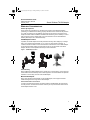
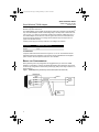
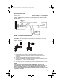
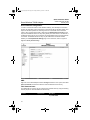
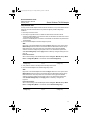
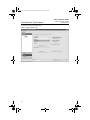
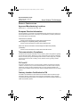
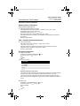
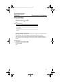
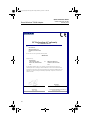
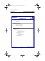
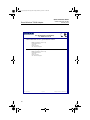
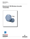
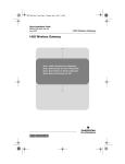
4075_QIG_Rev_BA.fm Page 1 Friday, February 19, 2010 11:08 AM Quick Installation Guide 00825-0100-4075, Rev BA February 2010 Smart Wireless THUM Adapter Smart Wireless THUM™ Adapter Start Wireless Considerations Bench Top Configuration Step 1: Physical Installation Step 2: Verify Operation Reference Information Product Certifications EC Declaration of Conformity End ¢00825-0100-4075[¤ 4075_QIG_Rev_BA.fm Page 2 Friday, February 19, 2010 11:08 AM Quick Installation Guide 00825-0100-4075, Rev BA February 2010 Smart Wireless THUM Adapter © 2010 Rosemount Inc. All rights reserved. All marks property of owner. Emerson Process Management Rosemount Temperature GmbH Emerson Process Management Frankenstrasse 21 Rosemount Division Asia Pacific Private Limited 8200 Market Boulevard Chanhassen, MN USA 55317 T (US) (800) 999-9307 T (Intnl) (952) 906-8888 F (952) 949-7001 63791 Karlstein Germany T 49 (6188) 992 0 F 49 (6188) 992 112 1 Pandan Crescent Singapore 128461 T (65) 6777 8211 F (65) 6777 0947 / (65) 6777 0743 [email protected] IMPORTANT NOTICE This installation guide provides basic guidelines for the Smart Wireless THUM Adapter. It does not provide instructions for detailed configuration, diagnostics, maintenance, service, troubleshooting, or installations. Refer to the THUM Adapter Reference Manual (document number 00809-0100-4075) for more instruction. The manual and this QIG are also available electronically on www.rosemount.com. WARNING Explosions could result in death or serious injury: Installation of this transmitter in an explosive environment must be in accordance with the appropriate local, national, and international standards, codes, and practices. Please review the Product Certifications section for any restrictions associated with a safe installation. • Before connecting a Field Communicator in an explosive atmosphere, ensure the instruments are installed in accordance with intrinsically safe or non-incendive field wiring practices. Electrical shock can result in death or serious injury: • Avoid contact with the leads and terminals. High voltage that may be present on leads can cause electrical shock. This device complies with Part 15 of the FCC Rules. Operation is subject to the following conditions. This device may not cause harmful interference. This device must accept any interference received, including interference that may cause undesired operation. This device must be installed to ensure a minimum antenna separation distance of 7.87-in. (20 cm) from all persons. IMPORTANT NOTICE During normal operation, or in fault condition, the THUM Adapter will cause a 2.5 V drop in the connected loop. It is important to ensure that the power supply can provide at least 2.5 V more than the minimum operating voltage of the wired device to make sure it works properly with the THUM Adapter installed. To determine the minimum operating voltage for the wired device, review the wired device operation and installation manual. 2 4075_QIG_Rev_BA.fm Page 3 Friday, February 19, 2010 11:08 AM Quick Installation Guide 00825-0100-4075, Rev BA February 2010 Smart Wireless THUM Adapter WIRELESS CONSIDERATIONS Power Up Sequence Power should not be applied to any wireless device until the Smart Wireless Gateway (“Gateway”) is installed and functioning properly. Wireless devices should also be powered up in order of proximity from the Gateway, beginning with the closest. This will result in a simpler and faster network installation. Enable Active Advertising on the Gateway to ensure that new devices join the network faster. For more information see the Smart Wireless Gateway Manual (Doc. No. 00809-0200-4420). THUM Adapter Position If possible, the THUM Adapter should be positioned vertically, either straight up or straight down, and it should be approximately 3 ft. (1 m) from any large structure, building, or conductive surface to allow for clear communication to other devices. If the THUM Adapter is mounted horizontally wireless communication range may be decreased. See THUM Adapter reference manual (00809-0100-4075) for more information. Figure 1. THUM Adapter Position Conduit Entry When installing the THUM Adapter into the conduit entry of a wired device, use an approved thread sealant. Thread sealant provides a water tight seal. The thread sealant also provides lubrication to ensure easy removal of the THUM Adapter. M20 Conduit Adapter When using the M20 Conduit Adapter on the THUM Adapter, use an approved thread sealant and tighten wrench tight to the THUM Adapter. Field Communicator Connections In order for the Field Communicator to interface with the THUM Adapter, the wired device must be powered. The Field Communicator must be put into poll mode and should use the THUM Adapter address of 63. 3 4075_QIG_Rev_BA.fm Page 4 Friday, February 19, 2010 11:08 AM Quick Installation Guide 00825-0100-4075, Rev BA February 2010 Smart Wireless THUM Adapter Power Supply Minimum loop load of 250 Ohms. The THUM Adapter communicates via and derives power from a standard 4-20 mA/HART® loop. The THUM Adapter causes a small voltage drop on the loop which is linear from 2.25 V at 3.5 mA to 1.2 V at 25 mA. Under fault conditions, the maximum voltage drop is 2.5 V. The THUM Adapter will not affect the 4-20 mA signal under normal or fault conditions as long as the loop has at least a 2.5 V margin at the maximum loop current (25 mA for a typical 4-20 mA/HART device). Limit the power supply to 0.5 Amps maximum, and voltage to 55 Volts DC. Loop Current THUM Adapter voltage drop 3.5 mA 25 mA 2.25 V 1.2 V Load Resistor If required, add a load resistor as shown in Figure 8, 12, and 16. The resistor should be adequately rated for the application (1W minimum) and be compatible with the supplied splice connector which accepts wire sizes from 14 to 22 AWG. BENCH TOP CONFIGURATION When performing bench top configuration it is suggested that you connect the THUM Adapter to a wired device. If this is not possible the following wiring diagrams can be used. For bench top configuration ensure that the power supply that you are using is limited to 0.5 Amps maximum. Figure 2. THUM Adapter Only, Powered by a Current Source (Such as a Fluke 744) THUM Adapter Green Ground Red + Black White - Yellow HART Modem 4 20 mA Current Source 4075_QIG_Rev_BA.fm Page 5 Friday, February 19, 2010 11:08 AM Quick Installation Guide 00825-0100-4075, Rev BA February 2010 Smart Wireless THUM Adapter Figure 3. THUM Adapter Only, Powered by a 24 V Power Supply with 1200 Ohm resistor to limit current to 20 mA THUM Adapter Green Ground + Red Black White - 20 mA Current Source 1200 Ohm Resistor Yellow HART Modem STEP 1: PHYSICAL INSTALLATION The THUM Adapter can be installed in one of two configurations: Direct Mount: The THUM Adapter is connected directly to the conduit entry of the wired device. Figure 4. Direct Mount Direct Mount 1. Install the HART device according to standard installation practices and the manufacturer’s instructions, being sure to use an approved thread sealant on all connections. 2. Attach the THUM Adapter to the wired device as shown in Figure 4. 3. Connect the THUM Adapter to the HART wired device using the wiring diagrams below. See Figures 21, 8, 10, and 12 on the following pages. 4. Close the housing cover on the HART wired device, so that metal touches metal, but do not over tighten to prevent damaging the unit. NOTE Two splice connectors are included with the THUM Adapter. The first is a two connection splice. The second is a three connection splice for use with a resistor, if there is not enough resistance in the loop. Both of these splice connectors can accept 14 to 22 gauge wire. See wired device reference manual for information on the required loop resistance. 5 4075_QIG_Rev_BA.fm Page 6 Friday, February 19, 2010 11:08 AM Quick Installation Guide Smart Wireless THUM Adapter 00825-0100-4075, Rev BA February 2010 Remote Mount Remote Mount: The THUM Adapter is mounted separate from the wired device housing and then connected to the wired device using conduit or other suitable means. Figure 5. Remote Mount 1. Install the HART device according to standard installation practices and the manufacturer’s instructions, being sure to use an approved thread sealant on all connections. 2. The THUM Adapter should be mounted as shown in Figure 5 on page 6. 3. Ground the Remote Mount Kit per local practices. 4. Connect the THUM Adapter to the wired device using standard practices. Wire running from the THUM Adapter to the wired device should be shielded or in conduit when installed in electrically noisy environments. 5. Connect the THUM Adapter to the HART wired device using the wiring diagrams below. See Figure 21, 8, 10, and 12 on the following pages. 6. Close the housing cover on the HART wired device, so that metal touches metal, but do not over tighten to prevent damaging the unit. NOTE Two splice connectors are included with the THUM Adapter. The first is a two connection splice. The second is a three connection splice for use with a resistor, if there is not enough resistance in the loop. Both of these splice connectors can accept 14 to 22 gauge wire. See wired device reference manual for information on the required loop resistance. 6 4075_QIG_Rev_BA.fm Page 7 Friday, February 19, 2010 11:08 AM Quick Installation Guide 00825-0100-4075, Rev BA February 2010 Smart Wireless THUM Adapter Wiring Diagrams The following is a list of the figure titles and page numbers for each direct mount and remote mount wiring diagram: Figure 6 - Direct Mount Wiring Diagram for 2-Wire Device on page 8 Figure 7 - Remote Mount Wiring Diagram for 2-Wire Device on page 8 Figure 8 - Direct Mount Wiring Diagram for 2-Wire Device with Resistor on page 9 Figure 9 - Remote Mount Wiring Diagram for 2-Wire Device with Resistor on page 9 Figure 10 - Direct Mount Wiring Diagram for 4-Wire Passive Device on page 10 Figure 11 - Remote Mount Wiring Diagram for 4-Wire Passive Device on page 10 Figure 12 - Direct Mount Wiring Diagram for 4-Wire Passive Device with Resistor on page 11 Figure 13 - Remote Mount Wiring Diagram for 4-Wire Passive Device with Resistor on page 11 Figure 14 - Direct Mount Wiring Diagram for 4-Wire Active Device on page 12 Figure 15 - Remote Mount Wiring Diagram for 4-Wire Active Device on page 12 Figure 16 - Direct Mount Wiring Diagram for 4-Wire Active Device with Resistor on page 13 Figure 17 - Remote Mount Wiring Diagram for 4-Wire Active Device with Resistor on page 13 Figure 18 - Direct Mount Wiring Diagram for 4-Wire Active Device with No 4-20 mA Loop on page 14 Figure 19 - Remote Mount Wiring Diagram for 4-Wire Active Device with No 4-20 mA Loop on page 14 Figure 20 - THUM Adapter only, Powered by a 24 V Power Supply with 1200 Ohm resistor to limit current to 20 mA on page 15 Figure 21 - THUM Adapter only, Powered by a 24 V Power Supply with 1200 Ohm resistor to limit current to 20 mA on page 15 7 4075_QIG_Rev_BA.fm Page 8 Friday, February 19, 2010 11:08 AM Quick Installation Guide 00825-0100-4075, Rev BA February 2010 Smart Wireless THUM Adapter Figure 6. Direct Mount Wiring Diagram for 2-Wire Device THUM Adapter Wired Device Green Ground Red 4-20 mA Loop + Black 4-20 mA Loop - White Yellow Splice Connector - PWR / COMM + PWR / COMM NOTE: In order for the THUM Adapter to function properly there must be at least 250 Ohms resistance in the loop. If the 4–20 mA loop does not have the required resistance, wire a resistor as shown in Figure 8, 12, or 16 as applicable. Figure 7. Remote Mount Wiring Diagram for 2-Wire Device THUM Adapter Remote Mount Housing Red Black Green Yellow 4-20 mA Loop + White Ground 4-20 mA Loop - Shield Wire + COMM To Wired Device - COMM 8 4075_QIG_Rev_BA.fm Page 9 Friday, February 19, 2010 11:08 AM Quick Installation Guide 00825-0100-4075, Rev BA February 2010 Smart Wireless THUM Adapter Figure 8. Direct Mount Wiring Diagram for 2-Wire Device with Resistor THUM Adapter Wired Device Green Ground Red 4-20 mA Loop + Black 4-20 mA Loop - White Yellow Resistor - PWR / COMM Splice Connector + PWR / COMM Figure 9. Remote Mount Wiring Diagram for 2-Wire Device with Resistor THUM Adapter Remote Mount Housing Red Resistor Black Green 4-20 mA Loop + Ground Yellow 4-20 mA Loop - White Shield Wire + COMM To Wired Device - COMM 9 4075_QIG_Rev_BA.fm Page 10 Friday, February 19, 2010 11:08 AM Quick Installation Guide 00825-0100-4075, Rev BA February 2010 Smart Wireless THUM Adapter Figure 10. Direct Mount Wiring Diagram for 4-Wire Passive Device THUM Adapter Wired Device Green Splice Connector Ground 4-20 mA Loop + Red 4-20 mA Loop - Black White Yellow Power + Power+ 4-20 mA/HART + 4-20 mA/HART - Power- Power - NOTE: A passive loop exists when the wired device is not supplying power to the 4–20 mA loop. It is important to verify if the wired device is operating in active or passive mode. Figure 11. Remote Mount Wiring Diagram for 4-Wire Passive Device THUM Adapter Remote Mount Housing Red Black Green Yellow 4-20 mA Loop + White 4-20 mA Loop - Ground Shield Wire + COMM - COMM 10 To Wired Device 4075_QIG_Rev_BA.fm Page 11 Friday, February 19, 2010 11:08 AM Quick Installation Guide 00825-0100-4075, Rev BA February 2010 Smart Wireless THUM Adapter Figure 12. Direct Mount Wiring Diagram for 4-Wire Passive Device with Resistor THUM Adapter Wired Device Green Splice Connector 4-20 mA Loop + Ground Red 4-20 mA Loop - Black White Resistor Yellow Power + Power+ 4-20 mA/HART + 4-20 mA/HART - Power- Power - Figure 13. Remote Mount Wiring Diagram for 4-Wire Passive Device with Resistor THUM Adapter Remote Mount Housing Red Green Resistor Black 4-20 mA Loop + Ground Yellow 4-20 mA Loop - White Shield Wire + COMM To Wired Device - COMM 11 4075_QIG_Rev_BA.fm Page 12 Friday, February 19, 2010 11:08 AM Quick Installation Guide 00825-0100-4075, Rev BA February 2010 Smart Wireless THUM Adapter Figure 14. Direct Mount Wiring Diagram for 4-Wire Active Device THUM Adapter Wired Device Green Ground Splice Connector 4-20 mA Loop + Yellow 4-20 mA Loop - White Black Red Power + 4-20 mA/HART - Power- 4-20 mA/HART + Power+ Power - NOTE: An active loop exists when the wired devices is supplying the power to the 4-20 mA loop. It is important to verify if the wired device is operating in active or passive mode. Figure 15. Remote Mount Wiring Diagram for 4-Wire Active Device THUM Adapter Remote Mount Housing Yellow Green White Red 4-20 mA Loop + Black 4-20 mA Loop - Ground Shield Wire + COMM - COMM 12 To Wired Device 4075_QIG_Rev_BA.fm Page 13 Friday, February 19, 2010 11:08 AM Quick Installation Guide 00825-0100-4075, Rev BA February 2010 Smart Wireless THUM Adapter Figure 16. Direct Mount Wiring Diagram for 4-Wire Active Device with Resistor THUM Adapter Wired Device Green Splice Connector Ground 4-20 mA Loop + Yellow 4-20 mA Loop - White Black Resistor Red Power + Power+ 4-20 mA/HART + 4-20 mA/HART - Power- Power - Figure 17. Remote Mount Wiring Diagram for 4-Wire Active Device with Resistor THUM Adapter Remote Mount Housing Yellow Resistor White Green 4-20 mA Loop + Ground Red 4-20 mA Loop - Black Shield Wire + COMM To Wired Device - COMM 13 4075_QIG_Rev_BA.fm Page 14 Friday, February 19, 2010 11:08 AM Quick Installation Guide 00825-0100-4075, Rev BA February 2010 Smart Wireless THUM Adapter Figure 18. Direct Mount Wiring Diagram for 4-Wire Active Device with No 4-20 mA Loop THUM Adapter Wired Device Green Ground Yellow Splice Connector Resistor White Black Red Power + Power+ 4-20 mA/HART + 4-20 mA/HART - Power- Power - Figure 19. Remote Mount Wiring Diagram for 4-Wire Active Device with No 4-20 mA Loop THUM Adapter Remote Mount Housing Yellow Green Resistor White Red Ground Black + COMM To Wired Device - COMM 14 4075_QIG_Rev_BA.fm Page 15 Friday, February 19, 2010 11:08 AM Quick Installation Guide 00825-0100-4075, Rev BA February 2010 Smart Wireless THUM Adapter Figure 20. THUM Adapter only, Powered by a 24 V Power Supply with 1200 Ohm resistor to limit current to 20 mA THUM Adapter Ground Green Red Black White 250 Ohm Resistor Yellow + 24 V Power - Supply 1200 Ohm Resistor Junction Box Figure 21. THUM Adapter only, Powered by a 24 V Power Supply with 1200 Ohm resistor to limit current to 20 mA THUM Adapter Remote Mount Housing + Ground 250 Ohm Resistor 24 V Power - Supply 1200 Ohm Resistor 15 4075_QIG_Rev_BA.fm Page 16 Friday, February 19, 2010 11:08 AM Quick Installation Guide 00825-0100-4075, Rev BA February 2010 Smart Wireless THUM Adapter Device Network Configuration In order to communicate with the Smart Wireless Gateway, and ultimately the Information System, the transmitter must be configured to communicate with the wireless network. This step is the wireless equivalent of connecting wires from a transmitter to the information system. Using a Field Communicator or AMS, enter the Network ID and Join Key so that they match the Network ID and Join Key of the gateway and other devices in the network. If the Network ID and Join Key are not identical, the THUM Adapter will not communicate with the network. The Network ID and Join Key may be obtained from the Smart Wireless Gateway on the Setup>Network>Settings page on the web server, shown in Figure 22. Figure 22. Gateway Network Settings AMS Right click on the THUM Adapter and select Configure. When the menu opens, select Join Device to Network and follow the method to enter the Network ID and Join Key. Field Communicator The Network ID and Join Key may be changed in the wireless device by using the following Fast Key sequence. Set both Network ID and Join Key. Function Wireless Setup 16 Key Sequence 1,4 Menu Items Smart Power, Network ID, Set Join Key, Radio State 4075_QIG_Rev_BA.fm Page 17 Friday, February 19, 2010 11:08 AM Quick Installation Guide 00825-0100-4075, Rev BA February 2010 Smart Wireless THUM Adapter Loop Current Test To verify that the THUM Adapter will work under all conditions, a loop current test should be performed. This test will exercise the loop under the highest possible voltage drop conditions. 1. Place loop in manual control. 2. Drive loop to high alarm level. For details see wired device instruction manual. • When the THUM Adapter is connected to a valve, this will need to be done at the current source and not from the valve. • When the THUM Adapter is connected to a transmitter, this will need to be performed at the transmitter. 3. Place the THUM Adapter into fixed voltage drop mode. AMS Right click on the THUM Adapter and select Configure. When the menu opens, select Manual Setup from the window on the left and select the Wired Device tab on the top. Make sure that the Time drop down menu at the bottom of the page has Current selected. Under the Voltage Drop drop down menu in the Smart Power Options box, select Fixed Voltage Drop. Hit the Apply button to make any changes. See Figure 23 on page 18. Field Communicator When communicating to the THUM Adapter select: Configure - Manual setup - Wired Device - Voltage Drop Mode. In the method choose Fixed Voltage Drop. Function Voltage Drop Key Sequence 2,2,2,2 Menu Items Voltage Drop 4. Verify that the current on the loop reaches the high alarm levels. 5. Place the THUM Adapter into variable voltage drop mode. AMS Right click on the THUM Adapter and select Configure. When the menu opens, select Manual Setup from the window on the left and select the Wired Device tab on the top. Make sure that the Time drop down menu at the bottom of the page has Current selected. Under the Voltage Drop drop down menu in the Smart Power Options box, select Variable Voltage Drop. Hit the Apply button to make any changes. See Figure 23. Field Communicator When communicating to the THUM Adapter select: Configure - Manual setup - Wired Device - Voltage Drop Mode. In the method choose Variable Voltage Drop. Function Voltage Drop Key Sequence 2,2,2,2 Menu Items Voltage Drop 17 4075_QIG_Rev_BA.fm Page 18 Friday, February 19, 2010 11:08 AM Quick Installation Guide Smart Wireless THUM Adapter 6. Remove loop from high alarm value. Figure 23. AMS Configure screen 18 00825-0100-4075, Rev BA February 2010 4075_QIG_Rev_BA.fm Page 19 Friday, February 19, 2010 11:08 AM Quick Installation Guide 00825-0100-4075, Rev BA February 2010 Smart Wireless THUM Adapter STEP 2: VERIFY OPERATION Operation can be verified in three locations: by using the Field Communicator, at the Gateway via the Smart Wireless Gateway’s integrated web server, or via AMS™ Wireless Configurator. Field Communicator For HART Wireless transmitter communication, a THUM Adapter DD is required.The Field Communicator must be put into poll mode using the THUM Adapter address of 63. Use the wired device documentation to connect the Field Communicator to the THUM Adapter. Figure 24. Field Communicator Connections Function Key Sequence Communications 3, 3 Menu Items Join Status, Wireless Mode, Join Mode, Number of Available Neighbors, Number of Advertisements Heard, Number of Join Attempts Smart Wireless Gateway If the THUM Adapter was configured with the Network ID and Join Key, and sufficient time has passed for network polling, the transmitter will be connected to the network. To verify device operation and connection to the network with the Smart Wireless Gateway’s integrated web server, open the Smart Wireless Gateway’s integral web interface and navigate to the Explorer page. NOTE: It may take several minutes for the device to join the network. AMS Wireless Configurator When the device has joined the network, it will appear in the Wireless Configurator as illustrated below. 19 4075_QIG_Rev_BA.fm Page 20 Friday, February 19, 2010 11:08 AM Quick Installation Guide Smart Wireless THUM Adapter 00825-0100-4075, Rev BA February 2010 Troubleshooting If the device is not operating properly, refer to the troubleshooting section of the manual. The most common cause of incorrect operation is the Network ID and Join Key. The Network ID and Join Key in the device must match that of the Smart Wireless Gateway. The Network ID and Join Key may be obtained from the Smart Wireless Gateway on the Setup>Network>Settings page on the web server. The Network ID and Join Key may be changed in the wireless device by using the following Fast Key sequence. Function Key Sequence Menu Items 1, 4 Smart Power, Network ID, Set Join Key, Radio State Wireless Setup REFERENCE INFORMATION NOTE: In order to communicate with a Field Communicator, the wired device must be powered. Table 1. THUM Adapter Fast Key Sequence Function Key Sequence Device Info 2, 2, 4, 3 Guided Setup 2, 1 Manual Setup 2, 2 Wireless 20 2, 2, 1 Menu Items Manufacturer, Model, Final Assembly Number, Universal, Field Device, Software, Hardware, Descriptor, Message, Date, Model Number I, II, III, SI Unit Restriction, Country Configure, Guided Setup, Join Device to Network, Configure Update Rate, Zero Trim, Configure Device Display, Configure Process Alarms Configure, Manual Setup, Wireless, Pressure, Device Temperatures, Device Information, Display, Other Network ID, Join Device to Network, Configure Update Rate, Configure Broadcast Power Level, Power Mode, Power Source 4075_QIG_Rev_BA.fm Page 21 Friday, February 19, 2010 11:08 AM Quick Installation Guide 00825-0100-4075, Rev BA February 2010 Smart Wireless THUM Adapter PRODUCT CERTIFICATIONS Approved Manufacturing Locations Rosemount Inc. – Chanhassen, Minnesota, USA European Directive Information The EC declaration of conformity for all applicable European directives for this product can be found at www.rosemount.com. A hard copy may be obtained by contacting an Emerson Process Management representative. ATEX Directive (94/9/EC) Emerson Process Management complies with the ATEX Directive. Electro Magnetic Compatibility (EMC) (2004/108/EC) Emerson Process Management complies with the EMC Directive. Radio and Telecommunications Terminal Equipment Directive (R&TTE) (1999/5/EC) Emerson Process Management complies with the R&TTE Directive. Telecommunication Compliance All wireless devices require certification to ensure that they adhere to regulations regarding the use of the RF spectrum. Nearly every country requires this type of product certification. Emerson is working with governmental agencies around the world to supply fully compliant products and remove the risk of violating country directives or laws governing wireless device usage. FCC and IC This device complies with Part 15 of the FCC Rules. Operation is subject to the following conditions: This device may not cause harmful interference. This device must accept any interference received, including interference that may cause undesired operation.This device must be installed to ensure a minimum antenna separation distance of 20 cm from all persons. Ordinary Location Certification for FM As standard, the transmitter has been examined and tested to determine that the design meets basic electrical, mechanical, and fire protection requirements by FM, a nationally recognized testing laboratory (NRTL) as accredited by the Federal Occupational Safety and Health Administration (OSHA). 21 4075_QIG_Rev_BA.fm Page 22 Friday, February 19, 2010 11:08 AM Quick Installation Guide 00825-0100-4075, Rev BA February 2010 Smart Wireless THUM Adapter Hazardous Locations Certificates North American Certifications Factory Mutual (FM) Approvals I5 FM Intrinsically Safe and Non-incendive Intrinsically Safe for Class I/II/III, Division 1, Groups A, B, C, D, E, F, and G. Zone Marking: Class I, Zone 0, AEx ia llC Temperature Codes T4 (-50 °C Tamb 70 °C) Non-incendive for Class I, Division 2, Groups A, B, C, and D. Intrinsically safe and non-incendive when installed according to Rosemount Drawing 00775-0010. Enclosure Type 4X/IP66 CSA - Canadian Standards Association I6 CSA Intrinsically Safe Intrinsically Safe for Class I, Division 1, Groups A, B, C, and D. T3C (-50 °C Tamb 70 °C) Intrinsically safe when installed according to Rosemount Drawing 00775-0012. Suitable for Class I, Division 2, Groups A, B, C, and D. Enclosure Type 4X/IP66 European Certifications I1 ATEX Intrinsic Safety Certificate No.: Baseefa09ATEX0125X Ex ia IIC T4 (-50 °C Tamb 70 °C) IP66 1180 II 1G Table 2. Input Parameters Loop Power Ui = 30V Ii = 200 mA Pi = 1.0 W Ci = 0 Li = 0 Special conditions for safe use (X) The surface resistivity of the antenna is greater than one gigaohm. To avoid electrostatic charge build-up, it must not be rubbed or cleaned with solvents or a dry cloth. The enclosure is made of aluminium alloy and given a protective polyurethane paint finish; however, care should be taken to protect it from impact or abrasion if located in a zone 0. N1 ATEX Type n Certificate No.: Baseefa09ATEX0131 Ex nA IIC T4 (-50 °C Tamb 70 °C) Ui = 45 Vdc MAX IP66 1180 22 II 3 G 4075_QIG_Rev_BA.fm Page 23 Friday, February 19, 2010 11:08 AM Quick Installation Guide 00825-0100-4075, Rev BA February 2010 Smart Wireless THUM Adapter IECEx Certifications I7 IECEx Intrinsic Safety Certificate No.: IECEx BAS 09.0050X Ex ia IIC T4 (-50 °C Tamb 70°C) IP66 Table 3. Input Parameters Loop Power Ui = 30V Ii = 200 mA Pi = 1.0 W Ci = 0 Li = 0 Special conditions for safe use (X) The surface resistivity of the antenna is greater than one gigaohm. To avoid electrostatic charge build-up, it must not be rubbed or cleaned with solvents or a dry cloth. The enclosure is made of aluminium alloy and given a protective polyurethane paint finish; however, care should be taken to protect it from impact or abrasion if located in a zone 0. N7 IECEx Type n Certificate No.: IECEx BAS 09.0058 Ex nA IIC T4 (-50 °C Tamb 70°C) Ui = 45 Vdc MAX IP66 23 4075_QIG_Rev_BA.fm Page 24 Friday, February 19, 2010 11:08 AM Quick Installation Guide 00825-0100-4075, Rev BA February 2010 Smart Wireless THUM Adapter EC Declaration of Conformity No: RMD 1077 Rev. B We, Rosemount Inc. 8200 Market Boulevard Chanhassen, MN 55317-6985 USA declare under our sole responsibility that the product, Model 775 manufactured by, Rosemount Inc. 12001 Technology Drive Eden Prairie, MN 55344-3695 USA and 8200 Market Boulevard Chanhassen, MN 55317-9687 USA to which this declaration relates, is in conformity with the provisions of the European Community Directives, including the latest amendments, as shown in the attached schedule. Assumption of conformity is based on the application of the harmonized standards and, when applicable or required, a European Community notified body certification, as shown in the attached schedule. 02/10/2010 (signature) Timothy Layer (name - printed) 24 (date of issue) Vice President Global Quality & Customer Care (function name - printed) 4075_QIG_Rev_BA.fm Page 25 Friday, February 19, 2010 11:08 AM Quick Installation Guide 00825-0100-4075, Rev BA February 2010 Smart Wireless THUM Adapter EC Declaration of Conformity No: RMD 1077 Rev. B EMC Directive (2004/108/EC) EN 61326-1: 2006 R&TTE Directive (1999/5/EC) EN 301 489-17: V1.3.2 (2007-6) EN 61010-1: 2001 (Second Addition) EN 300 328 V 1.7.1 (2006-10) ATEX Directive (94/9/EC) Model 775 Certificate: Baseefa09ATEX0125X Intrinsically Safe - Group II Category 1 G Ex ia IIC T4 (Ta =-50°C to +70°C) Harmonized Standards Used: EN60079-0:2006; EN60079-11:2007 Certificate: Baseefa09ATEX0131 Type n - Group II Category 3 G Ex nA IIC T4(Ta =-50°C to +70°C) Harmonized Standards Used: EN60079-0:2006; EN60079-15:2005 File ID: 775 CE Marking Page 2 of 3 K:\prodappr\EUCDOCS\775_RMD1077B.doc 25 4075_QIG_Rev_BA.fm Page 26 Friday, February 19, 2010 11:08 AM Quick Installation Guide 00825-0100-4075, Rev BA February 2010 Smart Wireless THUM Adapter EC Declaration of Conformity No: RMD 1077 Rev. B ATEX Notified Bodies for EC Type Examination Certificate Baseefa. [Notified Body Number: 1180] Rockhead Business Park Staden Lane Buxton, Derbyshire SK17 9RZ United Kingdom ATEX Notified Body for Quality Assurance Baseefa. [Notified Body Number: 1180] Rockhead Business Park Staden Lane Buxton, Derbyshire SK17 9RZ United Kingdom File ID: 775 CE Marking 26 Page 3 of 3 K:\prodappr\EUCDOCS\775_RMD1077B.doc 4075_QIG_Rev_BA.fm Page 27 Friday, February 19, 2010 11:08 AM Quick Installation Guide 00825-0100-4075, Rev BA February 2010 Smart Wireless THUM Adapter 27 4075_QIG_Rev_BA.fm Page 28 Friday, February 19, 2010 11:08 AM Quick Installation Guide Smart Wireless THUM Adapter 28 00825-0100-4075, Rev BA February 2010