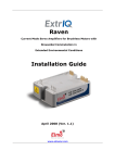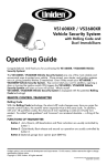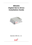
1
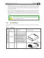
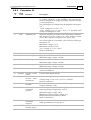
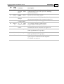
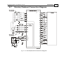
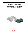
Ocarina/Castanet Analog Servo Drives Installation Guide April 2008- Ver. 1.2 www.elmomc.com Notice This guide is delivered subject to the following conditions and restrictions: This guide contains proprietary information belonging to Elmo Motion Control Ltd. Such information is supplied solely for the purpose of assisting users of the Ocarina and Castanet servo drives in their installation. The text and graphics included in this manual are for the purpose of illustration and reference only. The specifications on which they are based are subject to change without notice. Elmo Motion Control and the Elmo Motion Control logo are trademarks of Elmo Motion Control Ltd. Information in this document is subject to change without notice. Document No. MAN-OCSIG Copyright 2008 Elmo Motion Control Ltd. All rights reserved. Ocarina/Castanet Catalog Number: CAS- X/YY OCA- X/YYY Continuous Current (Amps) Maximum DC Operating Voltage Continuous Current (Amps) Maximum DC Operating Voltage Related Products: Evaluation Board Catalog Number Evaluation Board User Manual OCA-EVLBRD-1 (available upon request) MAN-EVLBRD-OCA (available on our web site) Revision History: Ver. 1.2 April 2008 Updated Power Ratings Table in Appendix Ver. 1.1 April 2007 Added section in Ch.4 about connecting to DC motors (MAN-OCSIG.PDF) Ver. 1.0 June 2006 Initial (MAN-OCSIG.PDF) Elmo Motion Control Ltd. Elmo Motion Control Inc. Elmo Motion Control GmbH 64 Gisin St., P.O. Box 463 Petach Tikva 49103 Israel 1 Park Drive, Suite 12 Westford, MA 01886 USA Steinkirchring 1 D-78056, Villingen-Schwenningen Germany Tel: +972 (3) 929-2300 Fax: +972 (3) 929-2322 Tel: +1 (978) 399-0034 Fax: +1 (978) 399-0035 Tel: +49 (0) 7720-85 77 60 Fax: +49 (0) 7720-85 77 70 [email protected] [email protected] [email protected] www.elmomc.com Ocarina/Castanet Installation Guide MAN-OCSIG (Ver. 1.2) Contents Chapter 1: Safety Information ............................................................................................... 1-1 1.1 Warnings.................................................................................................................... 1-2 1.2 Cautions ..................................................................................................................... 1-2 1.3 Directives and Standards ......................................................................................... 1-3 1.4 CE Mark Conformance ............................................................................................. 1-3 1.5 Warranty Information............................................................................................... 1-3 Chapter 2: Introduction........................................................................................................... 2-1 2.1 Product Description .................................................................................................. 2-1 2.2 Highlights .................................................................................................................. 2-1 2.3 Fault Protection ......................................................................................................... 2-2 2.4 How to Use this Guide ............................................................................................. 2-2 Chapter 3: Installation ............................................................................................................ 3-1 3.1 Before You Begin....................................................................................................... 3-1 3.1.1 Site Requirements ............................................................................................. 3-1 3.2 Unpacking the Amplifier.......................................................................................... 3-1 3.3 Dimensions ................................................................................................................ 3-2 3.3.1 Ocarina Dimensions ......................................................................................... 3-2 3.3.2 Castanet Dimensions........................................................................................ 3-2 3.4 Mounting ................................................................................................................... 3-3 3.4.1 Ocarina ............................................................................................................... 3-3 3.4.2 Castanet.............................................................................................................. 3-3 3.5 Integrating the Ocarina and Castanet on a PCB .................................................... 3-4 3.5.1 Traces.................................................................................................................. 3-4 3.5.2 Grounds and Returns....................................................................................... 3-4 3.6 Pin Functions ............................................................................................................. 3-5 3.6.1 Pinouts................................................................................................................ 3-5 3.6.2 Connector J1 ...................................................................................................... 3-6 3.7 Ocarina/Castanet Connection Diagram ................................................................. 3-8 3.8 Main Power and Motor Power ................................................................................ 3-9 3.9 Evaluation Board and Cable Kit .............................................................................. 3-9 3.10 DC Power Supply.................................................................................................... 3-10 3.11 Heat Dissipation...................................................................................................... 3-12 3.11.1 Ocarina ............................................................................................................. 3-12 3.11.1.1 Thermal Data......................................................................................... 3-12 3.11.1.2 Heat Dissipation Data........................................................................... 3-12 3.11.1.3 How to Use the Charts ......................................................................... 3-13 3.11.2 Castanet............................................................................................................ 3-13 Chapter 4: Servo Control Operation ..................................................................................... 4-1 4.1 Ocarina/Castanet Connected to DC Motors .......................................................... 4-1 4.2 Current Command Input ......................................................................................... 4-1 4.3 External Current Limit - Continuous (ECLC) ........................................................ 4-1 4.3.1 External Voltage................................................................................................ 4-1 i Ocarina/Castanet Installation Guide Contents MAN-OCSIG (Ver. 1.2) 4.3.2 4.3.3 4.3.4 4.3.5 4.3.6 External Resistor ............................................................................................... 4-2 External Current Limit - Peak (ECLP) ........................................................... 4-2 External Voltage................................................................................................ 4-2 External Resistor ............................................................................................... 4-3 Latch Mode (LM) .............................................................................................. 4-3 4.4 Status Indications ...................................................................................................... 4-3 Appendix: Specifications ......................................................................................................A-1 A.1 General Specifications..............................................................................................A-1 A.1.1 Ocarina .............................................................................................................. A-1 A.1.2 Castanet............................................................................................................. A-2 A.2 Standards Compliance.............................................................................................A-3 A.2.1 Quality Assurance ........................................................................................... A-3 A.2.2 Design................................................................................................................ A-3 A.2.3 Safety ................................................................................................................. A-3 A.2.4 EMC ................................................................................................................... A-4 A.2.5 Workmanship................................................................................................... A-4 A.2.6 PCB .................................................................................................................... A-4 A.2.7 Packing .............................................................................................................. A-4 ii Ocarina/Castanet Installation Guide MAN-OCSIG (Ver. 1.2) Chapter 1: Safety Information In order to achieve the optimum, safe operation of the Ocarina and Castanet servoamplifiers, it is imperative that you implement the safety procedures included in this installation guide. This information is provided to protect you and to keep your work area safe when operating the Ocarina and Castanet and accompanying equipment. Please read this chapter carefully before you begin the installation process. Before you start, ensure that all system components are connected to earth ground. Electrical safety is provided through a low-resistance earth connection. Only qualified personnel may install, adjust, maintain and repair the servo drive. A “qualified person” has the knowledge and authorization to perform tasks such as transporting, assembling, installing, commissioning and operating motors. The Ocarina and Castanet servo drives contain electrostatic-sensitive components that can be damaged if handled incorrectly. To prevent any electrostatic damage, avoid contact with highly insulating materials, such as plastic film and synthetic fabrics. Place the product on a conductive surface and ground yourself in order to discharge any possible static electricity build-up. To avoid any potential hazards that may cause severe personal injury or damage to the product during operation, keep all covers and cabinet doors shut. The following safety symbols are used in this manual: Warning: This information is needed to avoid a safety hazard, which might cause bodily injury. Caution: This information is necessary for preventing damage to the product or to other equipment. Note: This is auxiliary information that ensures the correct operation of the equipment. 1-1 Ocarina/Castanet Installation Guide Safety Information MAN-OCSIG (Ver. 1.2) 1.1 Warnings To avoid electric arcing and hazards to personnel and electrical contacts, never connect/disconnect the servo drive while the power source is on. Power cables can carry a high voltage, even when the motor is not in motion. Disconnect the Ocarina and Castanet from all voltage sources before they are opened for servicing. The Ocarina and Castanet servo drives contains grounding conduits for electric current protection. Any disruption to these conduits may cause the instrument to become hot (live) and dangerous. After shutting off the power and removing the power source from your equipment, wait at least 1 minute before touching or disconnecting parts of the equipment that are normally loaded with electrical charges (such as capacitors or contacts). Measuring the electrical contact points with a meter, before touching the equipment, is recommended. Cleaning after soldering To avoid the damage of the product's acrylic coating the Flute must not be cleaned after soldering by dissolving solvents and /or "water" cleaning process. For more details: www.elmomc.com/applications/article/Soldering-andCleaning_Application-Note.pdf 1.2 Cautions The Ocarina and Castanet servo drives contain hot surfaces and electrically-charged components during operation. The maximum DC power supply connected to the instrument must comply with the parameters outlined in this guide. When connecting the Ocarina and Castanet to an approved 12 ~ 95 VDC auxiliary power supply, connect it through a line that is separated from hazardous live voltages using reinforced or double insulation in accordance with approved safety standards. Before switching on the Ocarina and Castanet, verify that all safety precautions have been observed and that the installation procedures in this manual have been followed. 1-2 Ocarina/Castanet Installation Guide Safety Information MAN-OCSIG (Ver. 1.2) 1.3 Directives and Standards The Ocarina and Castanet conform to the following industry safety standards: Safety Standard Item In compliance with UL508c Power Conversion Equipment In compliance with UL840 Insulation Coordination, Including Clearance and Creepage Distances of Electrical Equipment In compliance with UL60950-1 (formerly UL1950) Safety of Information Technology Equipment, Including Electrical Business Equipment In compliance with EN60204-1 Low Voltage Directive, 73/23/EEC The Ocarina and Castanet servo drives have been developed, produced, tested and documented in accordance with the relevant standards. Elmo Motion Control is not responsible for any deviation from the configuration and installation described in this documentation. Furthermore, Elmo is not responsible for the performance of new measurements or ensuring that regulatory requirements are met. 1.4 CE Mark Conformance The Ocarina and Castanet servo drives are intended for incorporation in a machine or end product. The actual end product must comply with all safety aspects of the relevant requirements of the European Safety of Machinery Directive 98/37/EC as amended, and with those of the most recent versions of standards EN60204-1 and EN292-2 at the least. According to Annex III of Article 13 of Council Directive 93/68/EEC, amending Council Directive 73/23/EEC concerning electrical equipment designed for use within certain voltage limits, the Ocarina and Castanet meet the provisions outlined in Council Directive 73/23/EEC. The party responsible for ensuring that the equipment meet the limits required by EMC regulations is the manufacturer of the end product. 1.5 Warranty Information The products covered in this manual are warranted to be free of defects in material and workmanship and conform to the specifications stated either within this document or in the product catalog description. All Elmo drives are warranted for a period of 12 months from the time of installation, or 18 months from time of shipment, whichever comes first. No other warranties, expressed or implied — and including a warranty of merchantability and fitness for a particular purpose — extend beyond this warranty. 1-3 Ocarina/Castanet Installation Guide Introduction MAN-OCSIG (Ver. 1.2) Chapter 2: Introduction This Installation Guide is intended for design engineers who are integrating an Elmo Motion Control Ocarina and Castanet servo amplifiers into a machine. 2.1 Product Description The Ocarina and Castanet series of servo-amplifiers was designed to deliver “the highest possible power density”. The Ocarina can deliver up to 1.4 kW of continuous power or 2.8 kW of peak power in a matchbox size (2.25 in³ or 38cc) package. The Castanet delivers up to 240 W of continuous power or 480 W of peak power. The Ocarina and Castanet are designed for OEMs. They operate from a DC power source in current mode in conjunction with a DC Brush and Brushless motors (refer to section 4.1). The Ocarina and Castanet can operate as a stand-alone device. There are two categories of Ocarinas and Castanets, 60 VDC versions and 100 VDC versions. Power to the 60 V products is provided by a separate 0 ~ 59 V isolated DC power source. Power to the 100 V products is provided by a separate 0 ~ 95 V isolated DC power source. Note: There is a separate VL terminal for the control/logic supply input. In the 60 VDC models this terminal can be connected to an external 11 ~ 59 VDC isolated supply. In the 100 VDC models this terminal can be connected to an external 12 ~ 95 VDC isolated supply whenever the user wants to control the logic supply with an auxiliary low power voltage source. If power separation is not needed the VL and VP+ terminals can be shorted so that the main power supply will also power the control/logic supply and there will be no need for a separate control/logic supply. The Ocarina and Castanet are PCB mounted devices which enable efficient and cost saving implementation. 2.2 • • • • • • • • • • • • • Highlights Operates in current mode 0 ~ 59 VDC isolated DC power source for 60 V models 0 ~ 95 VDC isolated DC power source for 100 V models Zero deadband Excellent linearity Differential current command input Motor current monitor Current gain change for low inductance motors Status indication by four open collector optos External continuous and peak current-limit adjustments Interface via 2 mm pitch 0.51 mm square pins Package: plated AL 6063T5 with electroless nickel, plastic housing, UL94V0 recognized (Ocarina only) Ultra-compact size – Ocarina: 2.1" x 0.6" x 1.8" (55 x 15 x 46.5 mm), Castanet: 2" x 0.49" x 1.65" (51 x 12.5 x 42 mm) 2-1 Ocarina/Castanet Installation Guide Introduction MAN-OCSIG (Ver. 1.2) • 2.3 Weight: Ocarina – 1.6 oz (45g), Castanet – 0.76 oz (21.5 grams) Fault Protection Built-in protection against possible fault conditions, including: • Shorts between the outputs or between each output and the power input/return • Over-heating • Under/over voltage • Failure of internal power supplies • Latch mode for each protective feature 2.4 How to Use this Guide Installation is the first step in integrating and operating the Elmo Ocarina and Castanet servo amplifiers. After carefully reading the safety instructions in the first chapter, the following chapters provide you with installation instructions as follows: Chapter 3, Installation, provides step-by-step instructions for unpacking, mounting and connecting the Ocarina. Chapter 4, Servo Control Operation, explains how to control the operation of the servo amplifier. The Appendix, Technical Specifications, lists all the drive ratings and specifications. 2-2 Ocarina/Castanet Installation Guide Installation MAN-OCSIG (Ver. 1.2) 3-1 Chapter 3: Installation 3.1 Before You Begin 3.1.1 Site Requirements You can guarantee the safe operation of the Ocarina and Castanet by ensuring that they are installed in an appropriate environment. Feature Value Ambient operating temperature 0 °C – 50 °C (32 °F – 122 °F) Maximum relative humidity 90% non-condensing Operating area atmosphere No flammable gases or vapors permitted in area Note: Models for extended environmental conditions are available. The Ocarina and Castanet dissipate their heat by convection. The maximum ambient operating temperature of 0 °C – 50 °C (32 °F – 122 °F) must not be exceeded. 3.2 Unpacking the Amplifier To unpack the Ocarina and Castanet: Carefully remove the servo amplifier from the box and the Styrofoam. 1. Check the amplifier to ensure that there is no visible damage to the instrument. If any damage has occurred, report immediately to the carrier that delivered your amplifier. 2. To ensure that the Ocarina or Castanet you have unpacked is the appropriate type for your requirements, find the part number sticker on the side of the product: The P/N gives the type designation as follows: OCA- 5/100 Continuous Current (Amps) Maximum DC Operating Voltage 3. Verify that the Ocarina or Castanet type is the one that you ordered, and ensure that the voltage meets your specific requirements. Ocarina/Castanet Installation Guide Installation MAN-OCSIG (Ver. 1.2) 3.3 3.3.1 Dimensions Ocarina Dimensions Figure 3-1: Ocarina Dimensions 3.3.2 Castanet Dimensions Figure 3-2: Castanet Dimensions 3-2 Ocarina/Castanet Installation Guide MAN-OCSIG (Ver. 1.2) 3.4 Mounting 3.4.1 Ocarina Installation 3-3 The Ocarina was designed for mounting on a printed circuit board (PCB). It is connected by 2 mm pitch 0.51 mm square pins. When designing the Ocarina into a device, be sure to leave about 1 cm (0.4") outward from the heatsink to enable free air convection around the Ocarina. We recommend that the Ocarina be soldered directly to the board. Alternatively, the Ocarina can be attached to socket connectors mounted on the PCB. If the PCB is enclosed in a metal chassis, we recommend that the Ocarina be screw-mounted to it as well to help with heat dissipation. The Ocarina has screw-mount holes on each corner of the heatsink for this purpose. 3.4.2 Castanet The Castanet was designed for mounting on a printed circuit board (PCB). It is connected by 2mm pitch 0.51 mm square pins. When designing the Castanet into a device, be sure to leave about 1 cm (0.4") outward from the lower board to enable free air convection around the Castanet. We recommend that the Castanet be soldered directly to the board. Alternatively, the Castanet can be attached to socket connectors mounted on the PCB. Note: Elmo recommends you leave approximately 1 cm (0.4 in) of space on the side opposite the terminals to allow for free air convection. Ocarina/Castanet Installation Guide Installation MAN-OCSIG (Ver. 1.2) 3.5 3-4 Integrating the Ocarina and Castanet on a PCB The Ocarina and Castanet are designed to be mounted on a PCB, either by soldering its pins directly to the PCB or by using suitable socket connectors. In both cases the following rules apply: 3.5.1 Traces 1. The size of the traces on the PCB (thickness and width) is determined by the current carrying capacity required by the application. The rated continuous current limit (Ic)of the Ocarina and Castanet is the current used for sizing the motor traces (M1, M2, M3 and PE) and power traces (VP+, PR and PE). For control, feedbacks and inputs/outputs conductors the actual current is very small but “generous” thickness and width of the conductors will contribute to a better performance and lower interferences. 2. The traces should be as short as possible to minimize EMI and to minimize the heat generated by the conductors. 3. The spacing between the high voltage conductors (VP+, PR, M1, M2, M3, VL) must be at least: Surface layer: 1.5 mm Internal layer: 0.10 mm Complying with the rules above will help satisfy UL safety standards, MIL-STD-275 and the IPC-D-275 standard for non-coated conductors, operating at voltages lower than 100 VDC and at “unlimited altitudes” (above 10,000 meters – 30,000 feet). 3.5.2 Grounds and Returns The “Returns” of the Ocarina and Castanet are structured internally in a star configuration. The returns in each functional block are listed below: Functional Block Return Pin Power PR (Power Return) Internal Switch Mode P.S. PR (Power Return) Control section Internal, not accessible Feedback SUPRET (J2/2) The returns above are all shorted within the Ocarina and Castanet in a topology that results in optimum performance. 1. When wiring the traces of the above functions, on the Integration Board, the returns of each function must be wired separately to its designated terminal on the Ocarina and Castanet. DO NOT USE A COMMON GROUND PLANE. Shorting the commons on the Integration Board may cause performance degradation (ground loops, etc). 2. Return Traces: The return traces should be as large as possible, but without shorting each other, and with minimal cross-overs. 3. Main Power Supply and Motor Traces: The power traces must be kept as far away as possible from the feedback and control traces. Ocarina/Castanet Installation Guide Installation MAN-OCSIG (Ver. 1.2) 3-5 4. PE Terminal: The PE terminal is connected directly to the Ocarina's heatsink or to the Castanet's two PE strips on its lower board. In the Ocarina, the heatsink serves as an EMI common plane. The PE terminal should be connected to the system's Protective Earth. Any other metallic parts (such as the chassis) of the assembly should be connected to the Protective Earth as well. 5. Under normal operating conditions, the PE trace carries no current. The only time these traces carry current is under abnormal conditions (such as when the device has become a potential shock or fire hazard while conducting external EMI interferences directly to ground). When connected properly the PE trace prevents these hazards from affecting the drive. Follow these instructions to ensure safe and proper implementation. Failure to meet any of the above-mentioned requirements can result in drive/controller/host failure. 3.6 Pin Functions The Ocarina and Castanet are PCB mounted analog servo drives. Their pinouts are described below. 3.6.1 No. Pins Pinouts Type Port Function J1 I/O connector 2 M3 Motor power output 3 2 M2 Motor power output 2 M1 Motor power output 1 PE Protective earth 2 PR Power input return 2 VP+ Positive power input 1 VL Auxiliary power input 2X11 2 2 2 mm pitch 0.51 mm sq Connector Location Ocarina/Castanet Installation Guide Installation MAN-OCSIG (Ver. 1.2) 3.6.2 3-6 Connector J1 Pin # Short Form Function Description 1 EN+ Enable + Positive voltage input of the “Amplifier Enable” function. To enable operation of the amplifier, the optocoupler must be energized by applying voltage between this pin (+) and pin J1/22 (-). The optocoupler is isolated from the amplifier. See Figure 3-4. “OFF” voltage: 0 V < Vin < 1 V. “ON” voltage: 2.5 V < Vin < 10 V, 5 V typically with current consumption 2.5 mA. 2 AOK Amplifier OK When the amplifier is under normal operating conditions, this output is in the “active low“ state. When a failure occurs, this output is changed to the “open” state. The optocoupler is an isolated, open collector NPN type. See Figure 3-4. Maximum voltage = 30 V Maximum current = 8 mA “On” voltage: V OUT(On) < 0.8 V Refer to Section 4.4. 3 4 SO1 HA Status output 1 Hall A input 5 HB Hall B input 6 HC Hall C input 7 LATCH Latch mode 8 ECLRET 9 ECLC Current limits return External current limit continuous 10 CM 11 CREF+ Current command positive 12 CREF- 13 CMRET Current command negative Current monitor return Current monitor Specifications same as in pin J1/2. Logic levels: TTL Maximum input voltage: 15 VDC. Logic levels: TTL Maximum input voltage: 15 VDC. Logic levels: TTL. Maximum input voltage: 15 VDC. Latch mode input. For more details see the Latch Mode section in Chapter 4. Current limit signals return. External voltage scales down the rated value. Voltage range: 0 V to 3.75 V (3.75 V = rated Ic) Refer to Section 4.3. Analog output with a scale of ± 3.9 V for ± Ip. Output resistance: 1 kΩ Positive input of a differential amplifier: Input operating voltage range: ±3.75 V Maximum input voltage: ±20 V Maximum common mode voltage: ±6 V Differential input impedance: 40 kΩ Refer to Section 4.2. Negative input of a differential amplifier. Same specification as in pin J1/11. Current monitor (CM) signal return. Ocarina/Castanet Installation Guide Installation MAN-OCSIG (Ver. 1.2) Pin # Short Form 14 Function Description ECLP External current limit peak 15 LMRET 16 GAIN Latch Mode return Current gain change External voltage scales down the rated value. Voltage range: 0 V to 3.75 V (3.75 V = rated Ip) Refer to Section 4.2. Return for Latch Mode signals. 17 HARET 18 HALL+ 5V 19 SORET Status output return 20 SO2 Status output 2 21 SO3 Status output 3 22 EN- Enable - Hall supply voltage return +5 V Hall supply voltage 3-7 Shorting this pin to LMRET pin (J1/15) reduces the proportional gain of the current loop by 70%. Return used only for Hall supply. +5 V supply voltage for Hall sensors. Output current: maximum of 13 mA. Status output common AOK, SO1, SO2, SO3. Isolated from circuit common. See Figure 3-4. Status indication output 2. Same specification as in pin J1/2. Status indication output 3. Same specification as in pin J1/2. Negative voltage input of “Amplifier Enable” function. Optocoupler is isolated from the amplifier. For details, see pin J1/1. Ocarina/Castanet Installation Guide MAN-OCSIG (Ver. 1.2) 3.7 Ocarina/Castanet Connection Diagram Figure 3-3: Ocarina/Castanet Connection Diagram Installation 3-8 Ocarina/Castanet Installation Guide Installation MAN-OCSIG (Ver. 1.2) 3.8 Main Power and Motor Power Pin Function Cable VP+ Pos. Power input Power PR Power return Power PE Protective earth Power Pin Positions AC Motor DC Motor Motor Motor M1 Motor phase Motor N/C M2 Motor phase Motor Motor M3 Motor phase Motor Motor PE 3-9 Protective earth When connecting several amplifiers to several motors, all should be wired in the same motor phases and feedback sequences. This will enable the same SimplIQ program to run on all drives. Table 4-1: Connector for Main Power and Motor 3.9 Evaluation Board and Cable Kit A circuit board is available for evaluating the Ocarina and Castanet. It comes with standards terminal blocks for power connections and D-sub plugs/sockets for signals connections. The Evaluation Board is provided with a cable kit. Evaluation Board Catalog Number Evaluation Board User Manual OCA-EVLBRD-1 MAN-EVLBRD-OCA (available on our web site) Ocarina/Castanet Installation Guide Installation MAN-OCSIG (Ver. 1.2) 3.10 3-10 DC Power Supply The DC power supply can be at any voltage in the range defined in the technical specifications (the Appendix of this guide). The supply source must comply with the safety aspects of the relevant requirements, in accordance with the most recent version of the standard EN60950 or equivalent Low Voltage Directive Standard, all according to the applicable over-voltage category. If the power source to the power supply is the AC line (through an isolated transformer), safety margins must be considered, in order to avoid activating the under/over voltage protection due to line variations and/or voltage drop under load. In addition to the above, the transformer must comply with the safety aspects of the relevant requirements in accordance with the most recent version of the standard EN60742 (Isolating and Safety Isolating Transformers). The nominal DC bus voltage should be in the following range: 1.2 Vdcmin < Vdc < 0.9 Vdcmax where: Vdcmin is the minimum DC bus Vdcmax is the maximum DC bus The recommended minimum power supply capacitance for a single-phase rectified DC source connection is as follows: Amplifier Voltage Range 60 V 100 V Recommended capacitance ≥ 470 µF ≥470 µF The transformer power should be calculated such that it will be able to deliver power to the amplifier (including peak power) without significant voltage drops. The power supply should be located as close as possible to the amplifier. The maximum distance is 30 cm (1 foot). While driving high-inertia loads, the power supply must be equipped with a shunt regulator; otherwise, the amplifier will be disabled whenever the capacitors are charged above the maximum voltage, during motor break down. Ocarina/Castanet Installation Guide Installation MAN-OCSIG (Ver. 1.2) Figure 3-4: Detailed Ocarina/Castanet Internal Block Diagram 3-11 Ocarina/Castanet Installation Guide Installation MAN-OCSIG (Ver. 1.2) 3.11 Heat Dissipation 3.11.1 Ocarina 3-12 The best way to dissipate heat from the Ocarina is to mount it so that its heatsink faces up. For best results leave approximately 10 mm of space between the Ocarina's heatsink and any other assembly. 3.11.1.1 Thermal Data • • • Heat dissipation capability (θ): Approximately 10 °C/W. Thermal time constant: Approximately 240 seconds (thermal time constant means that the Ocarina will reach 2/3 of its final temperature after 4 minutes). Shut-off temperature: 86 °C – 88 °C (measured on the heatsink) 3.11.1.2 Heat Dissipation Data Heat Dissipation is shown in graphically below: Ocarina Whistle - 60 Series Power Dissipation 50V 40V 30V 20V 10.0 Power Dissipation (Watts 9.0 8.0 7.0 External Heatsink Required 6.0 5.0 Standard 40 °C Ambient Temp. 4.0 Heatsink not Required 3.0 2.0 1.0 0.0 0 0. 75 1. 5 2. 25 3 3. 75 4. 5 5. 25 6 Peak Current (A) 6. 75 7. 5 8. 25 9 9. 75 Ocarina/Castanet Installation Guide Installation MAN-OCSIG (Ver. 1.2) 3-13 Whistle-100 100 Series Power Dissipation Ocarina Power Dissipation (W) 6.0 5.0 External Heatsink Required Standard 40 °C Ambient Temp. 4.0 3.0 Heatsink not Required 2.0 1.0 5 4. 5 4 3. 5 3 2. 5 2 1. 5 1 0. 5 0 0.0 Peak Current (A) 85VDC 70VDC 50VDC 3.11.1.3 How to Use the Charts The charts above are based upon theoretical worst-case conditions. Actual test results show 30% - 50% better power dissipation. To determine if your application needs a heatsink: 1. Allow maximum heatsink temperature to be 80 °C or less. 2. Determine the ambient operating temperature of the Ocarina. 3. Calculate the allowable temperature increase as follows: • for an ambient temperature of 40 °C , ∆T= 80 °C – 40 °C = 40 °C 4. Use the chart to find the actual dissipation power of the drive. Follow the voltage curve to the desired output current and then find the dissipated power. 5. If the dissipated power is below 4W the Ocarina will need no additional cooling. Note: The chart above shows that no heatsink is needed when the heatsink temperature is 80 °C, ambient temperature is 40 °C and heat dissipated is 4 W. 3.11.2 Castanet The best way to dissipate heat from the Castanet is to mount it so that its lower board faces upwards. For best results leave approximately 10 mm of space between the Castanet's lower board and any other assembly. Ocarina/Castanet Installation Guide MAN-OCSRIG (Ver. 1.2) Chapter 4: Servo Control Operation 4.1 Ocarina/Castanet Connected to DC Motors In order to connect the Ocarina or Castanet to a DC motor, connect Hall A (J1 pin 4 of the drive) to Hall return (J1 pin 17 of the drive). The motor should be connected to M2, M3. 4.2 Current Command Input The Ocarina and Castanet have a single differential input. The input operating voltage range is ± 3.75 V, meaning that a 3.75 V signal will result in a fully rated peak current. The current limit circuits will override this signal if the peak duration exceeds 2.7 seconds and/or the required current exceeds the values set by the ECLC and ECLP signals. If the input command voltage exceeds 3.75 V, input scaling must be implemented by adding a pair of external resistors, according to the following formula: Rin (kΩ) = (5.33 * Vin) - 20 Be careful not to apply input voltage above the maximum allowed input voltage as this will cause the input operational amplifier to operate beyond its limits (±20 V) and in extreme cases, may even damage it. 4.3 External Current Limit - Continuous (ECLC) The continuous current limit of the Ocarina and Castanet amplifiers can be scaled down by an external voltage or by an external resistor connected from pin J1/9 (ECLC) to pin J1/8 (ECLRET). 4.3.1 External Voltage IC(new) = VECLC 3.75V * Ic(nom) An external positive voltage (0 to 3.75 V) to terminal J1/9 (ECLC) in reference to terminal J1/8 (ECLRET) will control the continuous current limit from zero to Ic (nom). The voltage is internally clamped to 3.75 V whenever the external VECLC is greater than 3.75V. The external voltage source must be able to source/ sink at least ±0.2 mA. The maximum absolute VECLC allowed to be connected is 5 V. 4-1 Ocarina/Castanet Installation Guide Servo Control Operation MAN-OCSRIG (Ver. 1.2) 4.3.2 External Resistor RECLC (Kohm) = 37.4 * Ic(new) Ic(nom) -1 Connect an external resistor between terminal J1/9 (ECLC) and terminal J1/8 (ECLRET). The resistor value is given by: 0 < RECLC < 36.4 K (1/8 Watt) At RECLC greater than 36.4 K, the current limit will be internally clamped to the nominal value. IC(nom) is the nominal continuous current limit of the amplifier. 4.3.3 External Current Limit - Peak (ECLP) The peak current limit of the Ocarina and Castanet amplifiers can be scaled down by an external voltage or by an external resistor connected between pin J1/14 (ECLP) and J1/8 (ECLRET). 4.3.4 External Voltage An external positive voltage (0 to 3.75 V) to terminal J1/14 (ECLP) in reference to terminal J1/8 (ECLRET) will control the peak current limit from zero to Ip(nom). Ip(new) = VECLP 3.75V * Ip(nom) The voltage is internally clamped to 3.75 V whenever the external VECLP is higher than 3.75 V. The external voltage source must be able to source/sink at least ±0.2 mA. The maximum absolute VECLP allowed to be connected is 5 V. 4-2 Ocarina/Castanet Installation Guide Servo Control Operation MAN-OCSRIG (Ver. 1.2) 4.3.5 External Resistor RECLP (Kohm) = 37.4 * Ip(new) -1 Ip(nom) Connect an external resistor between terminal J1/14 (ECLP) and terminal J1/8 (ECLRET). The resistor value is given by: 0 < RECLP < 36.4 K (1/8 Watt) At RECLP greater than 36.4 K, the current limit will be internally clamped to the nominal value. IP(nom) is the nominal peak current limit of the amplifier. 4.3.6 Latch Mode (LM) By connecting J1/7 to J1/15, the amplifier is latched to disable mode whenever a Short, Commutation or Over Temperature failure occurs. Disabling the amplifier temporarily by removing the power from Enable pin J1/1 resets the latch. Be sure to restore the Enable connection when the reason for the event no longer exists. 4.4 Status Indications The following table lists the Ocarina and Castanet amplifier status indications. Latch Option Function AOK SO1 SO2 SO3 1 Amplifier OK (AOK) N/A Low Open collector Open collector Open collector 2 External disable No Low Low Open collector Low 3 Current limit No Low Open collector Open collector Low 4 Short Yes Open collector Low Open collector Low 5 Over temperature Yes Open collector Open collector Low Low 6 Internal supplies protection No Open collector Low Low Open collector 7 Under voltage No Open collector Low Open collector Open collector 8 Over voltage No Open collector Open collector Low Open collector 9 Shunt* No Low Open collector Low Open collector 4-3 Ocarina/Castanet Installation Guide Servo Control Operation MAN-OCSRIG (Ver. 1.2) Latch Option Function AOK SO1 SO2 SO3 10 Power up reset No Open collector Open collector Open collector Open collector 11 Commutation failure Yes Open collector Low Low Low * This indication can be used as a digital input for activating an external shunt regulator. Table 4-1: Ocarina/Castanet Status Indications Notes: Without latch mode: The status indications are reset when the fault disappears. With latch mode: The Short, Over Temperature and Commutation Failure status indications are reset when the enable signal is temporarily removed from the enable input. Multiple faults: Only the reading of the first fault is reliable. Additional faults add on to the status outputs and the indication is therefore meaningless. 4-4 Ocarina/Castanet Installation Guide A-1 MAN-OCSIG (Ver. 1.1) Appendix: Specifications A.1 General Specifications A.1.1 Ocarina Feature Units 1/60 2.5/60 Minimum supply voltage VDC 11 20 Nominal supply voltage VDC 50 85 Maximum supply voltage VDC 59 95 Maximum continuous power output W Efficiency at rated power (at nominal conditions) % 55 140 5/60 280 10/60 15/60 1/100 2.5/100 5/100 10/100 15/100 570 850 90 230 460 A Peak current limit A 2 x Ic g (oz) 45 g (1.6 oz) mm (in) 55 x 15 x 46.5 (2.1"x 0.6" x 1.8") Mounting method 10 15 93% of DC bus voltage at f=32 kHz DC and trapezoidal commutation continuous current limit (Ic) Dimensions 1400 Up to 99% Maximum output voltage Weight 920 1 2.5 5 10 15 1 2.5 5 PCB mount (with 2mm pitch, 0.51 mm sq. pins) Ocarina/Castanet Installation Guide Specifications MAN-OCSIG (Ver. 1.1) A.1.2 Castanet Feature Units 3/60 2.5/100 Minimum supply voltage VDC 11 20 Nominal supply voltage VDC 50 85 Maximum supply voltage VDC 59 95 Maximum continuous power output W 190 240 Efficiency at rated power % Maximum output voltage Up to 99% 93% of DC bus voltage at f=32 kHz DC and trapezoidal commutation continuous current limit (Ic) A Peak current limit A 2 x Ic g (oz) 21.5 g (0.76 oz) mm (in) 51 x 12.5 x 42 (2" x .49" x 1.65") Weight Dimensions Mounting method 3.3 2.5 PCB mount (with 2 mm pitch, 0.51 mm sq. pins) A-2 Ocarina/Castanet Installation Guide Specifications MAN-OCSIG (Ver. 1.1) A.2 Standards Compliance A.2.1 Quality Assurance Specification Details ISO 9001:2000 Quality Management A.2.2 A-3 Design Specification Details MIL-HDBK- 217F Reliability prediction of electronic equipment (rating, de-rating, stress, etc.) IPC-D-275 Printed wiring for electronic equipment (clearance, creepage, spacing, conductors sizing, etc.) IPC-SM-782 IPC-CM-770 UL508c UL840 In compliance with IEC68 A.2.3 Type testing Safety Specification Details Recognized UL508c Power conversion equipment In compliance with UL840 Insulation coordination, including clearance and creepage distances of electrical equipment In compliance with UL60950 Safety of information technology equipment, including electrical business equipment In compliance with EN60204-1 Low voltage directive, 73/23/EEC Ocarina/Castanet Installation Guide Specifications MAN-OCSIG (Ver. 1.1) A.2.4 EMC Specification Details In compliance with Electromagnetic compatibility (EMC) EN55011 Class A with EN61000-6-2: Immunity for industrial environment, according to: IEC61000-4-2 / criteria B IEC61000-4-3 / criteria A IEC61000-4-4 / criteria B IEC61000-4-5 / criteria B IEC61000-4-6 / criteria A IEC61000-4-8 / criteria A IEC61000-4-11 / criteria B/C A.2.5 Workmanship Specification Details In compliance with IPC-A-610, level 2 Acceptability of electronic assemblies A.2.6 PCB Specification Details In compliance with IPC-A-600, level 2 Acceptability of printed circuit boards A.2.7 Packing Specification Details In compliance with EN100015 Protection of electrostatic sensitive devices A-4