1
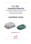
Raven Current Mode Servo Amplifiers for Brushless Motors with Sinusoidal Commutation in Extended Environmental Conditions Installation Guide April 2008 (Ver. 1.1) www.elmomc.com Notice This guide is delivered subject to the following conditions and restrictions: This guide contains proprietary information belonging to Elmo Motion Control Ltd. Such information is supplied solely for the purpose of assisting users of the Raven servo drives in their installation. The text and graphics included in this manual are for the purpose of illustration and reference only. The specifications on which they are based are subject to change without notice. Elmo Motion Control and the Elmo Motion Control logo are trademarks of Elmo Motion Control Ltd. Information in this document is subject to change without notice. Document No. MAN-RAVIG Copyright 2008 Elmo Motion Control Ltd. All rights reserved. RAV- XX/YYY Raven Catalog Number: Current Maximum Operating Voltage Revision History: Ver. 1.1 April 2008 Updated Power Ratings Table in Appendix Ver. 1.0 June 2007 Initial release (MAN-RAVIG.PDF) Elmo Motion Control Ltd. Elmo Motion Control Inc. Elmo Motion Control GmbH 64 Gisin St., P.O. Box 463 Petach Tikva 49103 Israel 1 Park Drive, Suite 12 Westford, MA 01886 USA Steinkirchring 1 D-78056, Villingen-Schwenningen Germany Tel: +972 (3) 929-2300 Fax: +972 (3) 929-2322 Tel: +1 (978) 399-0034 Fax: +1 (978) 399-0035 Tel: +49 (0) 7720-85 77 60 Fax: +49 (0) 7720-85 77 70 [email protected] [email protected] [email protected] www.elmomc.com Raven Installation Guide Contents MAN-RAVIG (Ver. 1.1) Contents Chapter 1: Safety Information ............................................................................................... 1-1 1.1 Warnings ......................................................................................................................... 1-1 1.2 Cautions .......................................................................................................................... 1-2 1.3 Conformance to Standards............................................................................................ 1-2 1.4 Warranty Information.................................................................................................... 1-3 Chapter 2: Introduction........................................................................................................... 2-1 2.1 ExtrIQ Product Family................................................................................................... 2-1 2.2 Product Description ....................................................................................................... 2-2 2.3 Standard Features .......................................................................................................... 2-2 2.4 Fault Protection .............................................................................................................. 2-2 2.5 How to Use this Guide .................................................................................................. 2-4 Chapter 3: Installation ............................................................................................................ 3-1 3.1 Site Requirements........................................................................................................... 3-1 3.2 Unpacking the Amplifier Components........................................................................ 3-1 3.3 Raven Dimensions.......................................................................................................... 3-2 3.4 Mounting the Raven ...................................................................................................... 3-3 3.4.1 Mounting the Heatsink ....................................................................................... 3-3 3.4.2 Mounting on the PC Board ................................................................................. 3-3 3.5 Wiring the Raven ........................................................................................................... 3-4 3.6 Connections .................................................................................................................... 3-5 3.6.1 Pin Functions........................................................................................................ 3-5 3.6.2 Connecting a Non-isolated Raven to an Isolating Power Transformer.......... 3-8 3.7 DC Power Supply........................................................................................................... 3-9 Chapter 4: Servo Control Operation ..................................................................................... 4-1 4.1 Current Command Input............................................................................................... 4-1 4.2 CFM ................................................................................................................................. 4-1 4.3 Current Gain Control (CGC)......................................................................................... 4-2 4.4 External Current Limit - Continuous (ECLC) ............................................................. 4-3 4.4.1 External Voltage................................................................................................... 4-3 4.4.2 External Resistor .................................................................................................. 4-3 4.5 External Current Limit - Peak (ECLP).......................................................................... 4-3 4.5.1 External Voltage................................................................................................... 4-3 4.5.2 External Resistor .................................................................................................. 4-4 4.6 Latch Mode (LM)............................................................................................................ 4-4 4.7 Amplifier Enable Logic.................................................................................................. 4-4 4.8 Status Indications ........................................................................................................... 4-5 Appendix: Technical Specifications ....................................................................................A-1 A.1 Power Ratings................................................................................................................A-1 A.2 Electrical Specifications ................................................................................................A-1 A.3 Mechanical Specifications.............................................................................................A-2 A.4 Environmental Conditions ...........................................................................................A-2 A.5 Standards Compliance..................................................................................................A-3 A.5.1 Quality Assurance...............................................................................................A-3 A.5.2 Design ..................................................................................................................A-3 i Raven Installation Guide Contents MAN-RAVIG (Ver. 1.1) A.5.3 A.5.4 A.5.5 A.5.6 A.5.7 A.5.8 A.5.9 Safety ....................................................................................................................A-3 EMC......................................................................................................................A-4 Workmanship......................................................................................................A-4 PCB .......................................................................................................................A-4 Packing.................................................................................................................A-4 WEEE* ..................................................................................................................A-4 RoHS.....................................................................................................................A-4 ii Raven Installation Guide MAN-RAVIG (Ver. 1.1) Chapter 1: Safety Information In order to achieve the optimum, safe operation of the Raven servo amplifier, it is imperative that you implement the safety procedures included in this user guide. This information is provided to protect you and to keep your work area safe when operating the Raven and accompanying equipment. Read this chapter carefully before you begin the installation process. Ensure that all system components are connected to earth ground. Electrical safety is provided through a low-resistance earth connection. Only qualified personnel may install, adjust, maintain and repair the servo amplifier. A “qualified person” has the knowledge and authorization to perform tasks such as transporting, assembling, installing, commissioning and operating motors. The Raven servo amplifier contains electrostatic-sensitive components that can be damaged if handled incorrectly. To prevent any electrostatic damage, avoid contact with highly insulating materials, such as plastic film and synthetic fabrics. Place the product on a conductive surface and ground yourself in order to discharge any possible static electricity build-up. To avoid any potential hazards that may cause severe personal injury or damage to the product during operation, keep all covers and cabinet doors shut. The following safety symbols are used in this manual: Warning: This information is needed to avoid a safety hazard, which might cause bodily injury. Caution: This information is necessary for preventing damage to the product or to other equipment. Note: This is auxiliary information that ensures the correct operation of the equipment. 1.1 Warnings Cleaning after soldering To avoid the damage of the product's acrylic coating the Raven must not be cleaned after soldering by dissolving solvents and /or "water" cleaning process. For more details: http://www.elmomc.com/applications/article/Soldering-andCleaning_Application-Note.pdf 1-1 Raven Installation Guide Safety Information MAN-RAVIG (Ver. 1.1) To avoid electric arcing and hazards to personnel and electrical contacts, never connect/disconnect the servo amplifier while the power source is on. Power cables can carry a high voltage, even when the motor is not in motion. Disconnect the Raven from all voltage sources before it is opened for servicing. After shutting off the power and removing the power source from your equipment, wait at least 5 minutes before touching or disconnecting parts of the equipment that are normally loaded with electrical charges (such as capacitors or contacts). Measuring the electrical contact points with a meter before touching the equipment is recommended. 1.2 Cautions The Raven servo amplifier contains hot surfaces and electrically-charged components during operation. The maximum DC power supply connected to the instrument must comply with the parameters outlined in this guide. 1.3 Conformance to Standards The Raven servo amplifier has been developed, produced, tested and documented in accordance with the relevant standards. Elmo Motion Control is not responsible for any deviation from the configuration and installation described in this documentation. Furthermore, Elmo is not responsible for the performance of new measurements or ensuring that regulatory requirements are met. The Raven servo amplifier is intended for incorporation in a machine or end product. The actual end product must comply with all safety aspects of the relevant requirements of the European Safety of Machinery Directive 89/392/EEC as amended, and with those of the most recent versions of standards EN60204-1 and EN292-2 at the least. According to Annex III of Article 13 of Council Directive 93/68/EEC, amending Council Directive 73/23/EEC concerning electrical equipment designed for use within certain voltage limits, the Raven meets the provisions outlined in Council Directive 73/23/EEC. The party responsible for ensuring that the equipment meet the limits required by EMC regulations is the manufacturer of the end product. 1-2 Raven Installation Guide 2-1 MAN-RAVIG (Ver. 1.1) Chapter 2: Introduction This user guide is intended for the design engineer who is integrating an Elmo Motion Control Raven servo amplifier into a machine. 2.1 ExtrIQ Product Family Elmo Motion Control's ExtrIQ product family is a set of durable motion control products for applications operating under extreme environmental conditions. The products are capable of withstanding the following extreme conditions: Ambient Temperature Range Non-operating conditions -50 °C to +100 °C (-58 °F to 212 °F) Operating conditions -40 °C to +70 °C (-40 °F to 160 °F) Temperature Shock Non-operating conditions -40 °C to +70 °C (-40 °F to 160 °F) within 3 min. Altitude Non-operating conditions Unlimited Operating conditions -400 m to 155,000 m (-1,300 ft to 510,000 ft) Non-operating conditions Up to 95% relative humidity noncondensing at 35 °C (95 °F) Operating conditions Up to 95% relative humidity noncondensing at 25 °C (77 °F), up to 90% relative humidity non-condensing at 42 °C (108 °F) Vibration Operating conditions 20 Hz –2,000 Hz, 14.6g Mechanical Shock Non-operating conditions ±40g; Half sine, 11 msec Operating conditions ±20g; Half sine, 11 msec Maximum Humidity ExtrIQ products have a high power density in the range of 10 W – 9000 W and current carrying capacity of up to 200 A (400A peak). ExtrIQ has been tested using methods and procedures specified in a variety of extended environmental conditions (EEC) standards including: • • • • • • MIL-STD-704- Aircraft, Electric Power Characteristics MIL-STD-810- Environmental Engineering Considerations and Laboratory Tests MIL-STD-1275- Characteristics of 28 Volt DC Electrical Systems in Military Vehicles MIL-STD-461- Requirements for the Control of Electromagnetic Interference Characteristics of Subsystems and Equipment MIL-HDBK-217- Reliability Prediction of Electronic Equipment ISO-9001:2000 Raven Installation Guide Introduction MAN-RAVIG (Ver. 1.1) 2.2 Product Description The Raven is a series of miniature ExtrIQ current mode servo amplifiers for brushless motors with sinusoidal commutation. Although highly compact, the Raven can withstand extended environmental conditions and support up to 35 Amps. This high power density servo amplifier can deliver up to 4800 W of peak power or 2400 W of continuous power in a miniature package. The servo amplifier offers significant operating features including excellent output linearity and zero dead band performance. The Raven incorporates custom mixed analog/digital ICs and a hybrid power stage. The basic configuration is a current mode amplifier targeting the OEM market. As such, no trimmers are used in the basic version. In addition to its compliance with relevant MIL standards, the Raven amplifier also meets UL508c and the relevant CE regulations. The Raven power stage is implemented on a single ceramic substrate. This design enables very high thermal conductivity, high current carrying capacity, improved EMC and good mechanical strength. The control section is implemented by dedicated custom ICs that contribute to enhanced performance. 2.3 Standard Features Operation in current mode Internal DC-to-DC converter, which allows for operation from a single supply Zero deadband Excellent linearity One differential input Motor current monitor Current gain change for low inductance motors Remote current gain control Current feedback multiplier for low current motors Status indication and remote control functions by four open collector transistors External continuous and peak current-limit adjustments Interface via soldering pins Package: plated-copper base plate, plastic housing, UL94V0 recognized Ultra-compact size 2.4 Fault Protection Built-in protection against possible fault conditions, including: Shorts between the outputs or between each output and the power input/return Over-temperature Under/over voltage Failure of internal power supplies Latch mode for each protective feature Under/over voltage 2-2 Raven Installation Guide Introduction MAN-RAVIG (Ver. 1.1) 10.5K 10K 20K CREF1+ (J1,2) 20K - CREF1- (J1,1) 20K + 10nF 100K AS 44.2K AD Current Loop Amp. - A 20K + Current loop Phase 1 20K CREF2+ (J1,4) 10K Current loop Phase 2 - 20K AD CREF2- (J1,3) 20K + 20K Current loop Phase 3 ECLC(J2,1) 1K ECLP(J2,3) 1K ECLRET(J2,2) CM1(J1,7) 21K CM2(J1,8) 21K CM3(J1,9) 21K Current Limits PWM CMRET(J1,10) Dr4 Dr3 Dr5 Dr2 AOK(J3,1) M1 Current Sensing SO1(J3,2) Dr6 M2 Dr1 M3 SO2(J3,3) Protections VP+ SO3(J3,4) PR SORET(J3,5) (J3,6) CFM(J2,6) CFM&CGC Logic 27.4K LM(J2,7) CGC(J2,5) 14.7K EN- (J2,10) 27.4K EN+ (J2,9) CGCRET(J2,4) LMRET(J2,8) Figure 2-1: Raven Block Diagram 2-3 Raven Installation Guide Introduction MAN-RAVIG (Ver. 1.1) 2.5 How to Use this Guide Installation is the first step in integrating and operating the Elmo Raven servo amplifier. After carefully reading the safety instructions in the first chapter, the following chapters provide you with installation instructions as follows: Chapter 3, Installation, provides step-by-step instructions for unpacking, mounting and connecting the Raven. Chapter 4, Servo Control Operation, explains how to control the operation of the servo amplifier. The Appendix, Technical Specifications, lists all the drive ratings and specifications. 2-4 Raven Installation Guide 3-1 MAN-RAVIG (Ver. 1.1) Chapter 3: Installation 3.1 Site Requirements You can guarantee the safe operation of the Raven by ensuring that it is installed in an appropriate environment. Feature Value Ambient operating temperature -40 °C ~ 70 °C (- 40 °C ~ 160 °F) Maximum case temperature 87 °C (188 °F) Note: Models for extended environmental conditions are available. 3.2 Unpacking the Amplifier Components To unpack the Raven: Carefully remove the servo amplifier from the box and the Styrofoam. 1. Check the amplifier to ensure that there is no visible damage to the instrument. If any damage has occurred, report immediately to the carrier that delivered your amplifier. 2. To ensure that the Raven you have unpacked is the appropriate type for your requirements, find the part number sticker on the side of the Raven: The P/N number at the top gives the type designation as follows: RAV- XX/YYY Current Maximum Operating Voltage 3. Verify that the Raven type is the one that you ordered, and ensure that the voltage meets your specific requirements. Raven Installation Guide Installation MAN-RAVIG (Ver. 1.1) 3.3 Raven Dimensions Figure 3-1: Raven Dimensions 3-2 Raven Installation Guide Installation MAN-RAVIG (Ver. 1.1) 3.4 Mounting the Raven 3.4.1 Mounting the Heatsink The Raven dissipates its heat by natural convection, up to loads of 500W. For higher output loads, the amplifier should be mounted on an additional heatsink or cooled by fan. There are two 4.5-mm holes in the base plate for mounting an additional heatsink (see Figure 3-1). 3.4.2 Mounting on the PC Board When mounting the Raven on a PC board, four screws (in addition to the solder pins) may be installed to provide a mechanical connection. It is important to provide a spacer if any components are located above the amplifier. Failure to do so can warp the PC board or puncture the amplifier case. When selecting screws, the following specifications should be used. If a spacer has been added, the screw length must be calculated to penetrate the case by no more than 2.6 mm. Screw Type: Phillips Pan Head Self-tapping (for plastic) screw – Nickel-plated Steel. Meets standards ISO 1478, EN 21478, or DIN 7970. d ST2.2 L 4.5* P 0.8 dk 4.2 k 1.8 m≈ 2.6 Phillips size 1 *4.5 mm is typical for mounting on a PC board assembly without spacers. Table 3-1: Dimensions in Millimeters Basic ISO Pitch Diameter Nr. P Main Diameter D1max ST2.2 2.24 2 0.8 Minor Diameter Flat End Diameter D1min D2max D2min D3max D3min 2.1 1.63 1.52 1.47 1.37 Table 3-2: Size Limits for Tapping Screw Thread 3-3 Raven Installation Guide Installation MAN-RAVIG (Ver. 1.1) 3.5 Wiring the Raven Figure 3-2: Basic Wiring 3-4 Raven Installation Guide Installation MAN-RAVIG (Ver. 1.1) 3.6 Connections 3.6.1 Pin Functions The Raven connections are described in the following figure and tables. Figure 3-3: Raven Connector Locations Pin Function Remarks VP+ Positive power input PR M1 Power input return Motor power output 1 M2 Motor power output 2 M3 Motor power output 3 Table 3-3: Raven Power Connections 3-5 Raven Installation Guide Installation MAN-RAVIG (Ver. 1.1) Pin #/ Short Form 1 CREF1- Function Remarks Current command Negative input of a differential amplifier: input ( - ) Input operating voltage range: ±3.75 V Maximum input voltage: ±20 V (see section 4.1) Maximum common mode voltage: ±6 V (referred to as CMRET) Differential input impedance: 40 kΩ 2 CREF1+ 3 CREF24 Current command Positive input of a differential amplifier. input ( + ) Specification as for pin J1/1. Current command Negative input of a differential amplifier. input ( - ) Specification as for pin J1/1. CREF2+ Current command Positive input of a differential amplifier. input ( + ) Specification as for pin J1/1. 5 N/C 6 N/C 7 Current monitor for M1 Analog output with a scale of ±3.9 V for ±Ip. Current monitor for M2 Analog output with a scale of ±3.9 V for ±Ip. Current gain change return Analog output with a scale of ±3.9 V for ±Ip. Current monitor return Return for the current monitor (CM) signals. CM1 8 CM2 9 CM3 10 CMRET Output resistance: 21 kΩ Output resistance: 21 kΩ Output resistance: 21 kΩ Table 3-4: Connector J1 3-6 Raven Installation Guide Installation MAN-RAVIG (Ver. 1.1) Pin #/ Short Form 1 ELCL Function Remarks External current limit - continuous External voltage scales down rated value. Voltage range: 0 V to 3.75 V (3.75 V = rated Ic) Internally limited to rated value 2 ECLRET 3 ECLP Current limits return Return for current limits signals. External current limit - peak External voltage scales down rated value. Voltage range: 0 V to 3.75 V (3.75 V = rated Ip) Internally limited to rated value 4 Current gain change return Return for CGC signal. Current gain change Shorting this pin to the CGCRET pin (J2/4) reduces the proportional gain (P) of the current loop by 70%. CFM Current feedback multiplier Shorting this pin to pin J2/5 (CGC) multiplies the current feedback signal by 2. 7 Latch mode Latch mode input. Latch mode return Return for Latch mode (LM). Enable ( + ) Positive voltage input of "Amplifier Enable” function. To enable operation of the amplifier, the opto must be switched on by applying voltage between this pin (+) and pin J2/10 (-). The opto is isolated from the amplifier. See Figure 2-1. CGCRET 5 CGC 6 LM 8 LMRET 9 EN+ Minimum “On” voltage: 3 V , current consumption 0.6 mA. Maximum “On” voltage: 15 V , current consumption 5.4 mA. 10 EN- Enable (-) Negative voltage input of “Amplifier Enable” function. Opto is isolated from the amplifier. For details, see pin J2/9. Table 3-5: Connector J2 3-7 Raven Installation Guide Installation MAN-RAVIG (Ver. 1.1) Pin #/ Short Form Function Remarks 1 Amplifier OK “Amplifier OK” indication output pin. When the amplifier is at normal operating conditions, this output is in “active low “ state. When a failure occurs, this output is changed to “open” state. Opto isolated, open collector NPN type. See Figure 2-1. AOK Maximum voltage = 30 V Maximum current = 8 mA. “On” voltage: V OUT(On) < 0.8 V 2 Status output 1 Status indication output 1. Specification as in pin J3/1. Status output 2 Status indication output 2. Specification as in pin J3/1. Status output 3 Status indication output 3. Specification as in pin J3/1. Status output return Status output return for AOK, SO1, SO2, SO3. Isolated from power input return. for details, see Figure 2-1. Status output return Status output return for AOK, SO1, SO2, SO3. Isolated from power input return. for details, see Figure 2-1. SO1 3 SO2 4 SO3 5 SORET 6 SORET Table 3-6: Connector J3 3.6.2 Connecting a Non-isolated Raven to an Isolating Power Transformer Be sure to ground: DC power common Motor chassis Amplifier heatsink Do not ground the control common, which is internally connected to the power common. Grounding the control common will create a ground loop. 3-8 Raven Installation Guide Installation MAN-RAVIG (Ver. 1.1) 3.7 DC Power Supply The DC power supply can be at any voltage in the range defined in the technical specifications (Appendix of this guide). The supply source must comply with the safety aspects of the relevant requirements, in accordance with the most recent version of the standard EN60950 or equivalent Low Voltage Directive Standard, all according to the applicable over-voltage category. If the power source to the power supply is the AC line (through a transformer), safety margins must be considered, in order to avoid activating the under/over voltage protection due to line variations and/or voltage drop under load. In addition to the above, the transformer must comply with the safety aspects of the relevant requirements in accordance with the most recent version of the standard EN60742 (Isolating and Safety Isolating Transformers). The nominal DC bus voltage should be in the following range: 1.2 Vdcmin < Vdc < 0.9 Vdcmax where: Vdcmin is the minimum DC bus Vdcmax is the maximum DC bus The recommended minimum power supply capacitance for single-phase connections is as follows: Amplifier Voltage Range 50 - 55 V 100 V 200 V Recommended capacitance 5600 µF 3300 µF 1500 µF The transformer power should be calculated such that it will be able to deliver power to the amplifier (including peak power) without significant voltage drops. The power supply should be located as close as possible to the amplifier. The maximum distance is 30 cm (1 foot). While driving high-inertia loads, the power supply must be equipped with a shunt regulator; otherwise, the amplifier will be disabled whenever the capacitors are charged above the maximum voltage. 3-9 Raven Installation Guide 4-1 MAN-RAVIG (Ver. 1.1) Chapter 4: Servo Control Operation 4.1 Current Command Input The Raven has two differential inputs. The input operating voltage range is ± 3.75 V, meaning that a 3.75 V signal will result in a fully rated peak current. The current limit circuits will override this signal if the peak duration exceeds 2.7 seconds and/or the required current exceeds the values set by the ECLC and ECLP signals. If the input command voltage exceeds 3.75 V, input scaling must be implemented by adding a pair of external resistors, according to the following formula: Rin (KΩ) = (5.33 * Vin) - 20 Be careful not to apply input voltage above the maximum allowed input voltage as this will cause the input operational amplifier to operate beyond its limits (+20 V) and in extreme cases, may even damage it. 4.2 CFM The amplifier is equipped with a current feedback multiplier (CFM). Connecting pin J2/6 to J2/5 multiplies the signal of the current feedback by 2 and consequently causes the following changes to occur: Current gains are divided by 2. Current monitor is multiplied by 2. Current limits are divided by 2. This function should be activated whenever the rated current and the peak current of the motor are less than 50% of the amplifier rated continuous and peak limits, respectively. Continuous Peak Current Current Current limit Limit Gain(A/V) Current Monitor (V/A) Differential Input Impedance Without CFM Ic Ip Ip/3.75 3.9/Ip 40 kΩ With CFM Ic/2 Ip/2 Ip/7.5 7.8/Ip 40 kΩ Table 4-1: CFM Effects The default (pin J2/6 left open) is the low current feedback. For permanent selection, a simple short is recommended. For remote selection, the scheme in Figure 4-1 should be used. Raven Installation Guide Servo Control Operation MAN-RAVIG (Ver. 1.1) 4.3 Current Gain Control (CGC) The Raven amplifier is equipped with Current Gain Control (CGC) for improved performance of low induction motors. Connecting pin J2/5 to J2/4 reduces the gain of the current loop, thus enabling the use of low inductance motors without the insertion of an additional inductor. The default (pin J2/5 left open) is high gain. Shorting this pin to the circuit common pin (J2/4) reduces the proportional gain (P) of the current loop by approx. 70%. For permanent selection, a simple short is recommended. For remote selection, the following scheme should be used. Figure 4-1: CFM and CGC Remote Control The following table should be used for calculating minimum inductance values. Minimum Inductance for High Gain Minimum Inductance for Low Gain 5/60 L Load (millihenry) > 12*10-3 * Vsupply (Volt) L Load (millihenry) > 4.8*10 -3 * Vsupply (Volt) 10/60 L Load (millihenry) > 6*10-3 * Vsupply (Volt) L Load (millihenry) > 2.4*10 -3 * Vsupply (Volt) 15/60 L Load (millihenry) > 4*10-3 * Vsupply (Volt) L Load (millihenry) > 1.6*10 -3 * Vsupply (Volt) 25/60 L Load (millihenry) > 2.4*10-3 * Vsupply (Volt) L Load (millihenry) > 0.9*10 -3 * Vsupply (Volt) 3/100 L Load (millihenry) > 27*10-3 * Vsupply (Volt) L Load (millihenry) > 6.6*10 -3 * Vsupply (Volt) 10/100 L Load (millihenry) > 9*10 -3 * Vsupply (Volt) L Load (millihenry) > 2.2*10 -3 * Vsupply (Volt) 15/100 L Load (millihenry) > 6*10 -3 * Vsupply (Volt) L Load (millihenry) > 1.5*10 -3 * Vsupply (Volt) 20/100 L Load (millihenry) > 4*10 -3 * Vsupply (Volt) L Load (millihenry) > 1.1*10 -3 * Vsupply (Volt) 2/200 L Load (millihenry) > 49.5*10 -3 * Vsupply (Volt) L Load (millihenry) > 12*10 -3 * Vsupply (Volt) 6/200 L Load (millihenry) > 16.5*10 -3 *Vsupply(Volt) L Load (millihenry) > 4*10 -3 * Vsupply (Volt) 10/200 L Load (millihenry) > 10*10 -3 *Vsupply(Volt) L Load (millihenry) > 2.4 -3 * Vsupply (Volt) 15/200 L Load (millihenry) > 6.5*10 -3 *Vsupply(Volt) L Load (millihenry) > 1.6 -3 * Vsupply (Volt) Table 4-2: Minimum Inductance Values 4-2 Raven Installation Guide Servo Control Operation MAN-RAVIG (Ver. 1.1) 4.4 External Current Limit - Continuous (ECLC) The continuous current limit of the Raven amplifier can be scaled down by an external voltage or by an external resistor connected from pin J2/1 (ECLC) to pin J2/2 (ECLRET). 4.4.1 External Voltage An external positive voltage (0 to 3.75 V) to terminal J2/1 (ECLC) in reference to terminal J2/2 (ECLRET) will control the continuous current limit from zero to Ic(nom). IC(new) = VECLC 3.75V * Ic(nom) The voltage is internally clamped to 3.75 V whenever the external VECLC is greater than 3.75 V. The external voltage source must be able to source/ sink at least ±0.4 mA. The maximum absolute VECLC is 12 V. 4.4.2 External Resistor Connect an external resistor between terminal J2/1 (ECLC) and terminal J2/2 (ECLRET). The resistor value is given by: RECLC (Kohm) = 12.5 * Ic(new) Ic(nom) -1 0 < RECLC < 11.4 K (1/8 Watt) At RECLC greater than 11.4 K, the current limit will be internally clamped to the nominal value. IC(nom) is the nominal continuous current limit of the amplifier. 4.5 External Current Limit - Peak (ECLP) The peak current limit of the Raven amplifier can be scaled down by an external voltage or by an external resistor connected between pin J2/3 (ECLP) and pin J2/2 (ECLRET). 4.5.1 External Voltage An external positive voltage (0 to 3.75 V) to terminal J2/3 (ECLP) in reference to terminal J2/2 (ECLRET) will control the peak current limit from zero to Ip(nom). Ip(new) = VECLP 3.75V * Ip(nom) The voltage is internally clamped to 3.75 V whenever the external VECLP is higher than 3.75 V. The external voltage source must be able to source/sink at least ±0.4 mA. The maximum absolute VECLP is 12 V. 4-3 Raven Installation Guide Servo Control Operation MAN-RAVIG (Ver. 1.1) 4.5.2 External Resistor Connect an external resistor between terminal J2/3 (ECLP) and terminal J2/2 (ECLRET). The resistor value is given by: RECLP (Kohm) = 12.5 * Ip(new) Ip(nom) -1 0 < RECLP < 11.4 K (1/8 Watt) At RECLP greater than 11.4K, the current limit will be internally clamped to the nominal value. IP(nom) is the nominal peak current limit of the amplifier. 4.6 Latch Mode (LM) By connecting J2/7 to J2/8, the amplifier can be latched to Disable mode whenever a Short or Over Temperature failure occurs. Disabling the amplifier temporarily (removing the power from Enable pins J2/9 and J2/10) resets the latch. Be sure to restore the Enable connection when the reason for the event no longer exists. For permanent selection, a simple short is recommended. For remote selection, use the following scheme. Figure 4-2: LM Remote Control 4.7 Amplifier Enable Logic Pins J2/9 and J2/10 are the inputs of an opto-coupler, which must be energized to enable operation of the amplifier. If the Enable input is kept high before turning on the amplifier, the amplifier power output will be active immediately upon power on. 4-4 Raven Installation Guide Servo Control Operation MAN-RAVIG (Ver. 1.1) 4.8 4-5 Status Indications The following table lists the Raven amplifier status indications. Function Latch Option AOK SO1 SO2 SO3 1 Amplifier OK (AOK) N/A Low Open collector Open collector Open collector 2 External disable No Low Low Open collector Low 3 Current limit No Low Open collector Open collector Low 4 Short Yes Open collector Low Open collector Low 5 Over temperature Yes Open collector Open collector Low Low 6 Internal supplies No protection Open collector Low Low Open collector 7 Under voltage No Open collector Low Open collector Open collector 8 Over voltage No Open collector Open collector Low Open collector 9 Shunt* No Low Open collector Low Open collector 10 Power Up Reset No Open collector Open collector Open collector Open collector * This indication can be used as a digital input for activating an external shunt regulator. Table 4-3: Raven Status Indications Notes: Without latch mode: The status indications are reset when the fault disappears. With latch mode: The Short and Over Temperature Failure status indications are reset when the enable signal is temporarily removed from the enable input. Multiple faults: Only the reading of the first fault is reliable. Additional faults add on to the status outputs and the indication is therefore meaningless. Raven Installation Guide A-1 MAN-RAVIG (Ver.1.1) Appendix: Technical Specifications Feature Units Minimum supply voltage VDC 10 20 40 Nominal supply voltage VDC 50 85 170 Maximum supply voltage VDC 59 95 195 Maximum continuous power output W Efficiency at rated power (at nominal conditions) % 240 480 720 1200 260 800 1200 1600 360 15/200 10/200 6/200 2/200 20/100 15/100 10/100 3/100 25/60 15/60 10/60 5/60 A.1 Power Ratings 960 1600 2400 > 97 Maximum output voltage Up to 100% of DC bus voltage Sinusoidal continuous current magnitude A Peak current limit A 5 10 15 Mounting method 25 3.3 10 15 20 2.25 6 10 15 2 x Ic PCB mount A.2 Electrical Specifications Feature Details Switching frequency on the load 32 kHz (±5%) Current loop bandwidth Up to 4 kHz Current step response <70 µsec Peak current duration (full rated peak current) 2.7 sec ±15% Continuous current limit tolerance -1% +5% Peak current limit tolerance -1% +5% Current gain linearity Better than ±1% of rated continuous current Current gain accuracy Better than ±5% for 0.05 Ic < lmotor > Ip Current monitor accuracy Better than ±5% for 0.05 Ic < lmotor > Ip Raven Installation Guide Technical Specifications MAN-RAVIG (Ver.1.1) A.3 Mechanical Specifications Feature Details Size 82 x 62 x 25.4 mm (3.228 x 2.440 x 1.000 in) Weight 250 g (8.8 oz) Power pin material Brass with tin plating Power pin size 1.14 mm (0.45 in) square Power pin PCB layout 1.8 ± 0.05 mm (0.071 ± 0.002 in) Signal pin (J1, J2) material Phosphor bronze with 10µ gold plating Signal pin (J1, J2) size 0.5 ± 0.1 mm (0.02 ± 0.004 in) square Signal pin (J1, J2) PCB layout 1 ± 0.05 mm (0.04 ± 0.002 in) A.4 Environmental Conditions Non-operating conditions -50 °C to +100 °C (-58 °F to 212 °F) Operating conditions -40 °C to +70 °C (-40 °F to 160 °F) Temperature Shock Non-operating conditions -40 °C to +70 °C (-40 °F to 160 °F) within 3 min. Altitude Non-operating conditions Unlimited Operating conditions -400 m to 155,000 m (-1,300 ft to 510,000 ft) Non-operating conditions Up to 95% relative humidity non-condensing at 35 °C (95 °F) Operating conditions Up to 95% relative humidity non-condensing at 25 °C (77 °F), up to 90% relative humidity non-condensing at 42 °C (108 °F) Vibration Operating conditions 20 Hz –2,000 Hz, 14.6g Mechanical Shock Non-operating conditions ±40g; Half sine, 11 msec Operating conditions ±20g; Half sine, 11 msec Ambient Temperature Range Maximum Humidity A-2 Raven Installation Guide Technical Specifications MAN-RAVIG (Ver.1.1) A-3 A.5 Standards Compliance A.5.1 Quality Assurance Specification Details ISO 9001:2000 Quality Management A.5.2 Design Specification Description In compliance with MIL-STD-704 Aircraft, Electric Power Characteristics In compliance with MIL-STD-810 Environmental Engineering Considerations and Laboratory Tests In compliance with MIL-STD-1275 Characteristics of 28 Volt DC Electrical Systems in Military Vehicles In compliance with MIL-STD-461 Requirements for the Control of Electromagnetic Interference Characteristics of Subsystems and Equipment In compliance with MIL-HDBK-217 Reliability Prediction of Electronic Equipment IPC-D-275 IPC-SM-782 IPC-CM-770 UL508c UL840 In compliance with VDE0160-7 (IEC68) A.5.3 Reliability prediction of electronic equipment (rating, de-rating, stress, etc.) Printed wiring for electronic equipment (clearance, creepage, spacing, conductors sizing, etc.) Type testing Safety Specification Details Recognized UL508c Power conversion equipment In compliance with UL840 Insulation coordination, including clearance and creepage distances of electrical equipment In compliance with UL60950 Safety of information technology equipment, including electrical business equipment In compliance with EN60204-1 Low voltage directive, 73/23/EEC Raven Installation Guide Technical Specifications MAN-RAVIG (Ver.1.1) A.5.4 A-4 EMC Specification Details In compliance with Electromagnetic compatibility (EMC) EN55011 Class A with EN61000-6-2: Immunity for industrial environment, according to: IEC61000-4-2 / criteria B IEC61000-4-3 / criteria A IEC61000-4-4 / criteria B IEC61000-4-5 / criteria B IEC61000-4-6 / criteria A IEC61000-4-8 / criteria A IEC61000-4-11 / criteria B/C A.5.5 Workmanship Specification Details In compliance with IPC-A-610, level 3 Acceptability of electronic assemblies A.5.6 PCB Specification Details In compliance with IPC-A-600, level 3 Acceptability of printed circuit boards A.5.7 Packing Specification Details In compliance with EN100015 Protection of electrostatic sensitive devices A.5.8 WEEE* Specification Description In compliance with 2002/96/EC Waste Electrical and Electronic Equipment regulations * Please send out-of-service Elmo drives to the nearest Elmo sales office. A.5.9 RoHS Specification Description In compliance with 2002/95/EC (effective July 2006) Restrictions on Application of Hazardous Substances in Electric and Electronic Equipment Raven Installation Guide MAN-RAVIG (Ver.1.1) Technical Specifications A-5