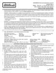
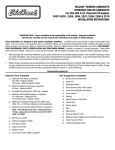
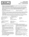
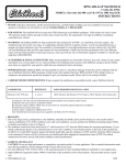
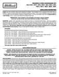
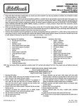
1
PERFORMER-PLUS CAMSHAFT / LIFTERS / LUBE KIT
CATALOG # 2162
MODEL: 396-454 c.i.d. Chevrolet V8 (1967 & later)
GENERAL INSTRUCTIONS
• Please study these instructions carefully before you remove your stock camshaft. If you have any questions or problems, do not hesitate to contact
our Technical Hotline at: 1-800-416-8628.
• These instructions are designed to give general installation guidelines. A complete step-by-step procedure manual would require many pages. If
you are a novice or just learning to work on automotive engines, we recommend consulting either Chilton or Motors automotive manuals before
you begin. You may also wish to contact an experienced mechanic. Be advised: improper installation may result in LOW MILEAGE, POOR PERFORMANCE, COSTLY REINSTALLATION AND EVEN ENGINE DAMAGE. Installing a camshaft is a complex procedure. Please follow these instructions carefully. Failure to do so may void your warranty.
• Before you begin the removal and installation process, please examine the kit for possible shipping damage. If the camshaft is damaged, contact
your dealer immediately. Also, make sure you have all the recommended tools and parts as listed below. As you read through these instructions
the first time, use the preparation checklist to check off the exact items you will need.
• Performer-Plus camshaft #2162 is ground specifically for use with the corresponding Edelbrock Performer intake manifold (#2161 or #3761),
Performer Series carburetors, and Tubular Exhaust Systems. They are dyno-matched and street proven to work as a team. However, the PerformerPlus camshaft package may be used by itself.
PREPARATION CHECKLIST
Tools & Equipment For Installation
• Box and open end wrenches
• Socket set
• Pliers (channel locks & hose clamp)
• Screw drivers (regular and phillips)
• Torque wrench
• Distributor wrench
• Timing light
• Hammer
• Vacuum gauge
• Harmonic balancer puller
• Crankshaft gear puller
• Gasket scraper or putty knife
• Water bucket
• Rags
• Engine oil & filter
• Masking tape (for tagging hoses and electrical wires)
Hardware & Parts To Buy
• Gaskets - OEM or equivalent
• Pipe plugs, if needed
• Edelbrock Gasgacinch #9300
• RTV Silicone Gasket Sealer
• Chalk Paper and pencil
• Radiator coolant
• Edelbrock Sure Seat Valve Springs, #5862
• Edelbrock Performer-Link True Rolling Timing
Chain and Gear Set, #7810
• Teflon tape
• Front cover oil seal, OEM or equivalent
REMOVAL OF ENGINE PARTS BEFORE CAMSHAFT INSTALLATION
Be sure to keep all parts in order
WARNING! DO NOT REMOVE RADIATOR CAP OR RADIATOR HOSES WHILE ENGINE IS HOT!
1. Disconnect the battery.
2. Drain radiator coolant. Drain plug will normally be located on lower
right or left side of the radiator facing the engine.
3. Remove radiator and air conditioning condenser if so equipped. In
some cases, the front grille may have to be removed. Measure distance from front cover to grille or brackets that may interfere with
camshaft against the length of the camshaft.
4. Disconnect fuel line and plug. CAUTION: Residual pressure may cause
fuel to spray out when connections are loosened.
5. Disconnect all linkage from carburetor such as throttle, throttle
springs, transmission, and cruise control.
6. Remove coil wires and sensor wires.
7. Tag and remove vacuum lines.
8. Remove valve covers.
9. Remove distributor cap and wires, rotate engine until rotor points
towards number 1 terminal in cap and pointer on front cover is on top
dead center (TDC) and remove distributor. Note the approximate position of the distributor housing in relation to the manifold to assist in
getting the distributor properly located during re-installation.
10. Remove carburetor and intake manifold. Remove and discard intake
manifold gasket.
11. Remove rocker arms and pushrods. Inspect all rockers and
pushrods and replace any showing excessive wear or damage.
12. Remove hydraulic valve lifters.
13. Remove crankshaft pulley, and using a suitable puller, crankshaft
dampener.
14. Remove water pump and front cover. You may need to loosen oil
pan bolts before removing front cover.
NOTE: The front cover oil seal should be replaced before the front cover
is re-installed.
©2008 Edelbrock Corp.
page 1
Rev. 9/08 - AJ/mc
Brochure #63-2162
15. Rotate engine until timing marks are aligned as in Figure 1.
16. Remove bolts retaining camshaft sprocket. Remove sprocket and
chain.
17. Remove crank sprocket using a gear puller.
18. Remove camshaft.
VALVE SPRINGS
WARNING ABOUT YOUR WARRANTY:—In order for this Performer-Plus
cam and lifter kit to be covered under ANY WARRANTY you must use
either the correct Edelbrock Sure Seat valve springs or the stock original equipment valve springs. Failure to do so could cause the cam
lobes to wear excessively and could cause additional engine damage.
1. This camshaft is designed to function either with the stock springs or
with Edelbrock Sure Seat valve springs #5862.
2. For older vehicles and vehicles with high mileage we highly recommend replacing the valve springs with Sure Seat Valve Springs #
5862.
3. Check spring height and set to factory specifications for correct year
and model (1.77"-1.83" for original springs with valve rotators; 1.88"
for Edelbrock #5862 without rotators).
DUE TO THE MANY POSSIBLE SETTINGS OVER THE YEARS, WE ADVISE
CHECKING MOTORS, CHILTON, OR FACTORY SERVICE MANUALS FOR
CORRECT SPRING HEIGHT FOR YOUR VEHICLE.
LIFTERS
1. New lifters must be used with a new camshaft. Use only the lifters
supplied with your kit .
2. Check to make sure all lifters fit freely in lifter bores.
INSTALLATION INSTRUCTIONS
1. Coat cam lobes and bottom of each lifter with MOS2 lube supplied
with your kit. THIS WILL PREVENT CAM LOBE AND LIFTER WEAR
FROM OCCURRING DURING INITIAL ENGINE START UP.
2. Install camshaft with timing marks lined up as recommended by factory specifications. See Figure 2.
CAUTION: When using Performer-Link True Rolling Timing Chain and Gear
Set #7810 with an Edelbrock cam and lifter kit, straight up timing
alignment is achieved. If any other timing gear set is used, it is necessary to check camshaft position for correct timing alignment. This
requires indexing the camshaft with a degree wheel to verify timing
alignment. O.E.M. or non-Edelbrock timing gear sets are not recommended for use with Edelbrock camshafts. Use locking compound
material on bolt threads holding gear to cam. Torque to factory recommendations (20 ft./lbs.).
3. Install new camshaft with new sprockets and timing chain.
NOTE: On computer-controlled engines, adjusting the lifter pre-load any
looser than specified may cause valve clatter which will activate the
knock detector and result in retarded ignition timing.
4. Install front timing cover with new gasket.
NOTE: Install new seal between oil pan and front cover if old seal is
damaged after removal. Use RTV silicone sealant on seal to ensure
proper seal to pan.
5. Torque front timing cover bolts to 6-7 ft./lbs.
6. Install front harmonic balancer and torque to 85 ft./lbs.
7. Install water pump using new gaskets and torque to 30 ft./lbs.
8. Install intake manifold using new intake gasket set and torque bolts to
25 ft/lbs. NOTE: Before installing intake manifold, you may want to
change the oil filter and pour the new motor oil into the lifter valley
over the new cam and lifters. This will aid lubrication upon initial
engine start-up.
DISTRIBUTOR INSTALLATION AND ENGINE TIMING
1. Turn the engine over in direction of rotation until the #1 intake valve
closes and continue until the pointer on the front cover is approximately five degrees before top dead center (BTDC). If valve cover is
already on engine, you may remove #1 spark plug and slowly rotate
engine until you can feel compression with your finger, then continue
until the pointer on the front cover is approximately five degrees
BTDC. See Figure 1 for firing order.
2. Re-install the distributor with the rotor pointing towards No. 1 terminal in the cap, and with the distributor housing in its original position.
If distributor will not drop down all the way to the flange on the manifold, it will be necessary to align the distributor shaft with the oil
pump drive. Slowly rotate the engine until the distributor drops down
against the manifold, then continue turning until the rotor is pointing
towards #1 terminal and the timing marks once again come to five
degrees BTDC.
3. Lightly tighten the hold-down clamp so that the distributor can still be
turned to determine final setting using a timing light with the engine
running.
4. Replace valve covers, throttle linkage and remaining vacuum and
electrical connections.
5. Engine oil & filter should be changed before start-up and again after
camshaft break-in.
CAMSHAFT & LIFTER RUN-IN
IMPORTANT:DO NOT ALLOW THE ENGINE TO RUN UNDER 2500 RPM
FOR THE FIRST 1/2 HOUR. Slow idle speeds may result in severe cam
and lifter wear.
START THE ENGINE AND BRING TO BREAK-IN RPM AS SOON AS POSSIBLE.
PUSHROD AND ROCKER ARM INSTALLATION—After the cam is installed
NOTE: Check all fuel lines and water hoses for leakage before trying to
and timed correctly (see Figure 2), install pushrods, lifters and rocker
start engine.
arms. Replace any worn or damaged rocker arms.
IMPORTANT NOTES AFFECTING YOUR WARRANTY
CAM LOBE WEAR— Cam lobe wear is almost non-existent unless
VALVE ADJUSTMENT
mismatched parts are used or installation of the cam and lifters are
1. Rotate engine until timing marks are aligned and #1 cylinder is at Top
done improperly. Most cam damage is caused by the timing gear
Dead Center (TDC). Back off rocker arm adjusting nut on #1 intake
loosening due to improper torque on bolts. Bolts holding gear to
and exhaust rocker arms until play in pushrod is detected.
camshaft should be torqued carefully and a locking compound applied
2. Tighten rocker arm nut until play in pushrod is eliminated, then tightto threads of bolts. Before installing your new Performer-Plus
en adjusting nut 1/2 additional turn. With engine at #1 firing position,
camshaft, check the gear drive on the distributor and oil pump for any
adjust intake valves 1,2,5, and 7 and exhaust valves 1,3,4, and 8.
signs of wear. If worn, be sure to replace with a new gear or you may
3. Rotate engine 1 complete turn (360 Þ) to #6 firing position and follow
wear out your camshaft prematurely. High-volume oil pumps are not
the same procedure for adjusting valves. With engine at #6 TDC,
recommended with Performer-Plus camshafts. Edelbrock camshafts
adjust intake valves 3,4,6 and 8 and exhaust valves 2,5,6 and 7.
are designed to use O.E.M. type gears only.
©2008 Edelbrock Corp.
Rev. 9/08 - AJ/mc
page 2
Brochure #63-2162
CAM GEARS AND CAMSHAFT END PLAY— If cam gear becomes loose, the cam will slide back in the block, causing the lifters to hit the lobes next to
them and also the cam bearing journals. If the engine is run after this happens, the bottom of the lifters and the sides of the lobes will become
chipped.
TUBULAR EXHAUST SYSTEM—For best performance, a tubular exhaust system is recommended with the Performer package to provide the most
low-end torque. Please consult your Edelbrock dealer or the Edelbrock catalog for a listing of available Edelbrock Tubular Exhaust Systems. Be
sure to check local emission control regulations for legality of camshaft and exhaust system changes.
IMPORTANT NOTE: When using Performer-Link True Rolling timing chain and gear sets (#7810) with an Edelbrock cam and lifter kit, straight up timing
alignment is achieved. If any other timing gear set is used, it is necessary to check camshaft position for correct timing alignment. This requires
indexing the camshaft with a degree wheel to verify timing alignment. O.E.M. or non-Edelbrock timing gear sets are not recommended for use
with Edelbrock camshafts.
Figure 1
396-454 c.i.d Chevrolet V8
Firing Order: 1-8-4-3-6-5-7-2
Turn distributor counter clockwise to advance timing
Timing Marks
Figure 2— Timing Chain Sprocket Alignment
©2008 Edelbrock Corp.
page 3
Rev. 9/08 - AJ/mc
Brochure #63-2162