1
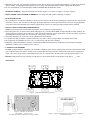
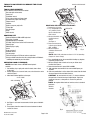
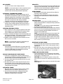
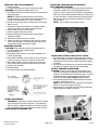
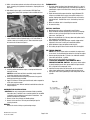
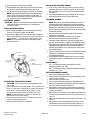
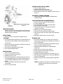
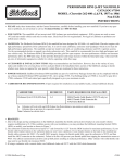
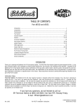
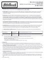
RPM AIR-GAP MANIFOLD
CATALOG #7501
MODEL: Chevrolet 262-400 c.i.d.V8, 1957 to 1986 Non-EGR
INSTRUCTIONS
• PLEASE study these instructions, and the General Instructions, carefully before installing your new manifold. If you have any
questions or problems, do not hesitate to call our Technical Hotline at: 1-800-416-8628.
• EGR SYSTEM: This manifold will not accept stock EGR (exhaust gas recirculation) equipment . EGR systems are used on some
1972 and later model vehicles and only in some states. Check local laws for requirements. Not legal in California on pollutioncontrolled motor vehicles.
• MANIFOLD: The Edelbrock RPM Air-Gap manifold has been designed for 262-400 c.i.d. small-block Chevrolet engines. The
manifold accepts late model water neck, air conditioning, alternator and H.E.I. ignition systems. Use the recommended electric or
manual type choke carburetors only. This manifold is recommended for street high performance and race vehicles only. The RPM
Air-Gap manifold provides good low rpm response for street performance vehicles and increases performance above the 5000 rpm
range. It also provides horsepower and torque increases, when used with any mix of aftermarket equipment available for vehicles operating from 1500-6500 RPM.
• ACCESSORIES & INSTALLATION ITEMS: Major recommendations are listed below. However, due to the variety of years, makes
and models to be covered, please review each part listed in the Installation Items section of the Edelbrock catalog to decide whether
more items are required for your specific vehicle than are mentioned in these instructions.
• POWER PACKAGE: Edelbrock RPM Air-Gap manifolds are part of a total Power Package System that can be completed with the
use of Edelbrock Performer RPM aluminum cylinder heads, dyno-matched Performer RPM camshaft #7102, springs, chain set,
carburetors and related parts specifically designed to give you maximum results. Please refer to our catalog for details.
• CARBURETOR RECOMMENDATIONS: If parts required for installation are unavailable locally, contact Edelbrock directly.
CARBURETOR
REFERENCE
PARTS REQUIRED FOR INSTALLATION
Performer #1407 (750 cfm)
A, I, K, O
#8036 Throttle Cable Bracket (1972-79 only) or #8012 Throttle Cable Extension Kit
A-Carburetor will work with non-EGR (Exhaust Gas Recirculation) or pre-emission control system.
I-Carburetor has no provision for evaporative canister.
K-Carburetor requires #8008 or #8024 stud, nut and washer kit. Determine length needed before installation.
O-Carburetor has manual choke only.
If electric choke is required use Edelbrock kit #1478.
Note: Manifold has been tested and proved compatible with Holley 0-4779 (750 cfm).
• BRACKETS
1. Due to the design and leg configuration on the Edelbrock manifold, the throttle and kick-down bracket on some model vehicles
requires modification to fit. If this condition occurs with your installation, you may purchase the Edelbrock mounting bracket #8036,
or modify your bracket as shown in Figure 3.
2. The carburetor location has been moved up by 0.7" and forward by 0.125" from the OEM location for maximum performance. If your
throttle cable bracket fastens to the carburetor pad you won’t have a problem. If your bracket fastens to the back of the manifold use
kit #8012. (To install #8012 properly, depress the throttle pedal fully, open the carburetor to WOT, and then install the #8012 extension
to the carburetor). Failure to do this will prevent your throttle pedal from tripping the transmission sensor at WOT. This affects
transmission kick-down and up-shift points resulting in reduced performance.
• GASKETS AND SEALANT
CAUTION: Do not use high performance or competition type intake gaskets for street application. Due to material deterioration under
street driving conditions, internal leakage of both vacuum and oil may occur.
1. Use only Edelbrock #7201, Fel-Pro #1205, or OE equivalent gasket set when installing Edelbrock manifolds for street applications.
2. Apply Edelbrock Gasgacinch sealant, #9300, to both sides of the manifold as well as head surfaces. This procedure ensures a good
seal.
© 1998 Edelbrock Corp.
12/98
3. Eliminate the end seals. Use automotive grade RTV silicone instead. Apply a bead of sealant approximately 1/4" high across the block
end seal surface, overlapping the intake gasket at the four corners. This method eliminates end seal slippage and deterioration.
4. For ease of installation, we recommend using Edelbrock Manifold Bolt & Washer Kit, #8504.
• MANIFOLD TORQUE—Torque all manifold bolts circled in Figure 1 to 25 ft/lbs. See Figure 1 for proper sequence.
• FIRING ORDER AND CYLINDER NUMBERING—For firing order and cylinder numbering, see Figure 2.
• REAR WATER BOSSES
We've included two 3/8"-NPT threaded holes over the rear water outlets of the heads. By plumbing the coolant from these outlets to the
front water crossover, you can reduce overall engine operating temperature. This has proved helpful in circle track racing applications.
If you don't wish to take advantage of this feature, plug the holes with two 3/8"-NPT pipe plugs included with the manifold.
• FINAL TUNING FOR OPTIMUM PERFORMANCE
NOTE: Local emission laws must be checked for legality of any carburetor or ignition changes.
1. Due to design, the fuel / air mixture and cylinder charging are very efficient with the RPM Air-Gap manifold. Generally speaking, the
stock jetting for the Performer Series carburetor #1407 will not need changing. Specific applications may show an increase in power by
enrichening the secondary jetting .003 from the stock setting (from 0.107" to 0.110").
2. Aftermarket distributor curve kits may be used with RPM Air-Gap manifolds.
3. Use modified or high performance cylinder heads such as our #6071 or #6073, and port-match the manifold to the heads.
4. The compression ratio should be at least 9.5 to 1 to work properly with the #7102 camshaft.
5. Installation of aftermarket headers, camshafts or both with an Edelbrock RPM Air-Gap manifold may lean carburetor calibration.
Should this condition occur, recalibrate with a richer jet.
• CAMSHAFT AND HEADERS
The RPM Air-Gap manifold is compatible with aftermarket camshafts and/or headers. Edelbrock has developed a dyno-matched, street
proven camshaft, the #7102 which is suitable for use with the RPM Air-Gap #7501.This camshaft will require the use of high performance rocker arms, studs, retainers, and Edelbrock Sure-Seat valve springs #5703. Header primary tube diameter should be 1-3/4".
• PLEASE complete and mail your warranty card. Be sure to write the model number of this product in the “Part #____” space.
THANK YOU
11
12
10
9
4
1
3
2
5
7
6
8
Figure 1—Intake Manifold Tightening Sequence
Figure 2—262-400 c.i.d. Chevrolet
Firing Order— 1-8-4-3-6-5-7-2
Turn Distributor Counter Clockwise to Advance Timing
Figure 3—Remove shaded area to provide clearance for throttle
or kick-down bracket
GENERAL INSTRUCTIONS
FOR INTAKE MANIFOLD
REMOVAL AND INSTALLATION
The following instructions must be carefully studied and understood before you remove your stock
manifold. Failure to follow these instructions may void the warranty.
NOTE: Included with your Edelbrock manifold package is a separate manifold instruction sheet. That instruction sheet lists carburetor
selection, installation parts, modifications (if needed), and all technical specifications. This must be read carefully. If you have any
questions please contact Edelbrock direct . See page #8.
CAUTION: Improper installation will result in:
Low Mileage
Poor Performance
Costly Re-Installation
To avoid these problems, you must use the preliminary checklist printed below for your convenience.
PRELIMINARY CHECK LIST:
❑ Carefully study and understand ALL instruction sheets.
❑ Carefully check the manifold instruction sheet to make sure it is the correct one.
❑ Inspect manifold for possible shipping damage (if damaged, contact your dealer immediately).
❑ Check all threaded holes.
❑ Check all internal passages with a light and a wire making sure they are clean and unobstructed.
❑ Use correct Edelbrock or OEM gaskets with Edelbrock Gasgacinch #9300 and RTV silicone sealant.
❑ Use Teflon tape or PST thread sealer on all pipe plugs, fittings and bolt threads.
❑ Remove dowel pins from end seal surface on Ford and Chrysler products. Use grip pliers for removal.
❑ Use correct carburetor and adapter if recommended. Always use a new carburetor base gasket.
❑ Re-install vacuum lines correctly and replace all bad lines with the correct size.
❑ Position manifold and follow torque sequence correctly as per instruction sheet.
❑ Set ignition timing to correct specification.
❑ Check carburetor, points, plugs, wires and distributor vacuum and mechanical advance systems to avoid possible
problems in the future.
❑ Check automatic transmission shift points before removal of your stock manifold, and adjust linkage after Edelbrock
manifold installation for same shift points (if needed).
❑ Check air/fuel ratio before and after new manifold installation.
❑ Check emission parts for proper function before removing stock manifold.
❑ Adjust the automatic choke correctly.
NOTE: We recommend that you refer to this checklist again AFTER installation to be sure you have completed all steps.
EDELBROCK WARRANTY
It is the constant endeavor of the Edelbrock Corporation to give our customers the highest quality of performance products obtainable. Edelbrock
warrants each new product to be free from defects in both workmanship and materials to a period of one year from date of purchase, provided
that the product is properly installed and subjected to normal use and service and that the product is not modified or altered in any way unless
specified by our instructions. Customers requiring warranty assistance should contact the dealer from whom they purchased the product. In
turn, the dealer will contact Edelbrock, and we will determine the method of satisfying the warranty.
Should Edelbrock determine that the product be returned to the factory, it should be accompanied by proof of purchase and a clear notation of
the exact problem encountered. The product must be returned freight pre-paid. If a thorough inspection of the product by the factory indicates
defects in workmanship or material, our sole obligation shall be to repair or replace the product. This warranty covers only the product itself and
not the cost of installation or removal.
EDELBROCK CORPORATION SHALL NOT BE LIABLE FOR ANY AND ALL CONSEQUENTIAL DAMAGES
OCCASIONED BY THE BREACH OF ANY WRITTEN OR IMPLIED WARRANTY PERTAINING TO THIS SALE, IN
EXCESS OF THE PURCHASE PRICE OF THE PRODUCT SOLD.
© 2001 Edelbrock Corporation
Brochure No. 63-0048
Page 1 of 8
Rev 1/02
HOOD CLEARANCE
THINGS TO DO BEFORE YOU REMOVE THE STOCK
MANIFOLD
C
B EA
D
AR
W
Fig. 2
AIR CLEANER
B EA
2-3"
D
D
CLAY CONE
AR
W
CHECKING HOOD CLEARANCE:
NOTE: Check hood clearance BEFORE removing stock
manifold.
1. Use modeling clay or putty and make five stools, two or three
inches high.
2. Position stools on air cleaner at front, rear, each side and on center
stud. See Figure 1.
3. Close hood to locked position and re-open.
MANIFOLD AND CARBURETOR HEIGHT:
1. Remove the air cleaner.
HEIGHT B
2. Lay a straightedge (such
as a yardstick) across
top of carburetor from
front to back.
3. Measure from block and
manifold end seal
surface.
See Figure 3.
4. Record measurements
HEIGHT A
in blank spaces labeled
OM1 and OM2.
5. Measure height of
Fig. 3
carburetor and record in
space C3.
NOTE: Most 4-bbl carburetors are about 3-1/4" tall (mounting
flange to air cleaner flange).
R
FO
SHOPPING LIST:
❑ Gaskets-Edelbrock, OEM or OEM equivalent
❑ Pipe plugs, if needed
❑ Edelbrock Gasgacinch (#9300)
❑ RTV High Temp silicone sealer or O/2 sensor safe
❑ Masking tape
❑ Modeling clay or putty
❑ Chalk
❑ Paper and pencil
❑ Radiator coolant
❑ Vacuum gauge
❑ Teflon thread tape or PST thread sealer or equivalent
❑ Check manifold instruction sheet for catalog numbers of Edelbrock
or OEM parts needed for your installation.
C
D
R
FO
TOOLS AND EQUIPMENT:
Use the following checklist for items needed:
❑ Box and open end wrenches
❑ Socket set
❑ Distributor wrench
❑ Pliers (channel locks and hose clamp)
❑ Screw drivers (regular and Phillips)
❑ Torque wrench
❑ Hammer
❑ Gasket scraper or putty knife
❑ Timing light
❑ Vacuum gauge
❑ Rags
❑ Water bucket
R
FO
6. Place straightedge on top of new manifold including any adapters
or gaskets you plan to use.
7. Measure distance from end seal surface as you did on stock
manifold. See Figure 4.
8. Record measurements in spaces NM1 and NM2.
9. Add carburetor measurement C3 to new manifold figures you
recorded.
10. If the new combination is taller, subtract this amount from the hood
clearance figure for the new hood clearance.
CAUTION: You must maintain at least 1/2" clearance between
the hood and air cleaner because of engine torque. If you have
insufficient clearance, a low profile air cleaner may solve the
problem.
NOTE: On engines without end seal surfaces, select a standard
point from
which to
measure.
D
AR
W
Fig. 1
4. See Figure 2 and record measurements in blank spaces labeled AB-C-D-E.
5. These figures show the amount of clearance between the hood
and the air cleaner.
Fig. 4
© 2001 Edelbrock Corporation
Brochure No. 63-0048
Page 2 of 8
Rev 1/02
AIR CLEANER:
Use stock air cleaners unless changing carburetor.
NOTE: If a new or replacement air cleaner is used, there may be
inadequate hood clearance. Make sure it performs the same
function as stock and meets legal emissions requirements.
AUTOMATIC TRANSMISSION CHECK:
1. To assure best performance, economy and emissions, the shift
point MUST be checked before and after the manifold change. We
suggest this method. From a standing start in drive, PUSH THE
THROTTLE WIDE OPEN. Hold in this position. Note speedometer
M.P.H. when it makes the first shift. After new manifold
installation, make the same test noting M.P.H. of the first shift.
2. If adjustment is necessary and to avoid possible transmission
damage, refer to manifold instruction sheet, your local dealer, a
transmission shop, or automotive repair manual for the correct
adjustment procedure.
CHECKING EMISSION LEVELS:
1. Where required by law, after making any equipment change to the
engine package, it is the responsibility of the consumer to make
certain all OEM emission equipment remains operational.
2. Edelbrock recommends that tailpipe levels be measured before and
after equipment installation. This procedure will provide guidelines
for keeping vehicle emission levels within legal limits.
3. Edelbrock cannot be responsible for vehicle emissions if all such
devices are not re-connected.
NOTE: If any emission part cannot be re-installed with your
Edelbrock manifold, contact: Edelbrock Corporation.
EGR SYSTEMS:
Exhaust Gas Recirculation (EGR) systems are used on some 1972
and later passenger cars, trucks and recreational vehicles. If your
vehicle has an EGR system, law requires that you retain this
system with your new Edelbrock manifold.
EXHAUST MANIFOLD HEAT RISER VALVE:
1. If your vehicle is equipped with an exhaust manifold heat riser
valve (generally located on the passenger side of vehicle below the
exhaust manifold), check the valve for proper operation.
2. This valve is spring-loaded and must work freely from the close to
open position by hand.
3. After engine warm up, the bi-metal spring must keep the valve in
the open position. If the valve does not open or opens only part
way, excessive exhaust heat will transfer through intake manifold,
causing damage to the manifold.
BRACKETS:
You may require some bracket parts or bracket modification when
replacing a 2-bbl carburetor with a 4-bbl carburetor. Refer to the
manifold instruction sheet for Edelbrock and OEM part numbers
needed and drawings of possible parts modification.
CLEAN ENGINE:
1. We recommend cleaning engine to prevent dirt from falling into
engine lifter valley or intake ports.
2. Cover ignition system Use Gunk (or equivalent) and a brush to
thoroughly clean manifold and the area between manifold and
valve covers.
3. Rinse with water and blow dry.
VACUUM LINES:
1. Vacuum lines are a major source of manifold, carburetor, and
ignition malfunction problems causing poor mileage, performance,
and high emissions.
CAUTION: It is very critical that the procedure outlined below
be followed and completed with extreme care.
2. Before removing stock manifold, you may either make a sketch or
tag each vacuum line with masking tape showing where each line
goes on the carburetor, manifold, distributor, transmission, all
emission sensors and EGR valve.
NOTE: You are dealing with two types of vacuum signals. No. 1
is called Manifold Vacuum. No. 2 is called Timed Port Vacuum.
Each has its particular function and must be connected correctly
for proper engine, transmission, ignition, emission and accessory
function. Use the following procedure to determine one from the
other and note it on your sketch or tags.
MANIFOLD VACUUM CHECK:
1. Start the engine with vehicle out of gear, set the brake and block
the wheels. Idle until engine is warm and the automatic choke is
completely off.
2. With engine at idle, place a vacuum gauge or your finger over the
end of each line and check for vacuum. If it shows vacuum, note
on your sketch or tag as “manifold vacuum”. As seen below.
TIMED PORT VACUUM CHECK:
1. For lines not showing vacuum in the previous test, open throttle
slowly to about 1500 rpm. If you now show some vacuum, note on
tags or sketch as “timed port vacuum”.
CAUTION: Vacuum line fatigue is common. It is wise, at this
time, to replace all vacuum lines, making sure you use the correct
size.
NOTE: Remember all lines must be re-connected to their proper
vacuum source.
AUTOMATIC CHOKE:
1. With engine cold and not running, remove air cleaner and open
throttle by hand. This will allow the choke blade to close.
2. By hand, feel how much tension is holding the blade closed.
Preliminary setting should be the same AFTER manifold
installation. See choke section on later pages.
© 2001 Edelbrock Corporation
Brochure No. 63-0048
Page 3 of 8
Rev 1/02
REMOVING THE STOCK MANIFOLD:
1. Disconnect battery.
2. For ease of installation, keep all parts in some sort of order.
WARNING: Do not remove manifold if engine is hot.
3. Drain radiator coolant (drain plug will normally be located on lower
right facing engine).
NOTE: See individual manifold installation sheet for water
draining requirement. Some engines do not require draining, such
as Cadillac, 383-440 Chryslers, 351-C and 351-M Fords.
4. Remove gas cap to relieve pressure. Disconnect fuel line and plug.
Replace gas cap.
5. Disconnect all linkage from carburetor such as throttle, throttle
springs, transmission, cruise control and automatic choke.
6. Tag and remove coil wires and sensor wires.
7. Remove previously marked vacuum lines.
8. Remove radiator hose, thermostat housing and thermostat, if
mounted on manifold.
10. Remove all brackets that are on the manifold.
11. Loosen or remove valve cover bolts on valve covers for manifold
removal and replacement. It may be necessary to replace valve
cover gaskets, if broken, to prevent oil leakage.
REMOVING IGNITION:
CAUTION: Follow instructions carefully, as serious damage can
occur when ignition is not installed correctly.
1. Remove distributor cap.
2. Note position of rotor and make a mark on the distributor case in
line with the rotor point.
3. Note position of distributor vacuum canister and place one type of
mark on valve cover or firewall in line with the vacuum outlet.
4. Note position of points (or magnetic trigger wheel), if open, how
much; if closed, note the distance from point block to cam lobe.
5. See Figure 5 for all details.
6. Remove distributor.
7. Do not rotate engine after removing distributor.
INSTALLING YOUR EDELBROCK MANIFOLD
PORT SURFACE CLEANING:
See Figure 6. To prevent gasket pieces from falling into ports and
combustion chambers when cleaning old gaskets from head
surfaces, lay rags in lifter galley and stuff paper or rags into ports.
When clean, remove stuffing carefully making sure all particles fall
on rags in lifter galley. Carefully remove rags containing particles.
Wipe surfaces clean with rags using lacquer thinner to remove
any oil or grease.
NOTE: This is a MUST to ensure proper sealing.
Figure 6
INSTALLING FITTINGS, PIPE PLUGS & STUDS:
1. Do not over-tighten or cross-thread fittings, pipe plugs, studs or
bolts in your aluminum manifold. Damage to threads or a cracked
mounting boss may result unless caution is used when installing
accessories.
2. Use Teflon tape or PST thread sealer or equivalent. Install fittings,
pipe plugs and carburetor studs from your stock manifold.
GASKET SURFACE PREPARATION:
CAUTION: Always use new gaskets as recommended. Check
with gasket manufacturer for compatibility with aluminum intake
manifolds. We recommend Fel-Pro Printoseal gaskets. The use of
Permatorque gaskets can lead to improper sealing due to the
hardness of the gasket. Don’t USE Permatorque gaskets.
1. Check gaskets on head surface and manifold to make sure they
are correct. Beaded side faces up.
NOTE: In some cases there may be a right and left side gasket
difference. Be sure they are placed correctly.
2. Coat head surface and cylinder head side of intake gaskets with
Edelbrock Gasgacinch #9300. See Figure 7.
Figure 5
Figure 7.
DOWEL PIN REMOVAL:
WARNING: On most Chrysler and Ford engines, there are dowel
pins in the front and rear valley seal surfaces. These dowel pins
MUST be removed. Edelbrock manifolds are not drilled for dowel
pins and will not seal if they are not removed. Damage may result.
PREPARATION PROCEDURE FOR
© 2001 Edelbrock Corporation
Brochure No. 63-0048
Page 4 of 8
Rev 1/02
3. Within a few minutes gaskets and surface will become tacky to the
touch. Carefully place gaskets on head surface, aligning ports and
bolt holes.
4. With Gasket in place apply a small amount of RTV High Temp
silicone sealer around water passages intake manifold side. See
Figure 8.
Figure 8
5.. With Edelbrock manifolds, you must use RTV High Temp silicone
sealer instead of end seal gaskets. Apply a 1/4" thick ribbon of
sealant across each end seal surface. Some installation require
02 sensor safe silicone See Figure 9.
Figure 9
MANIFOLD INSTALLATION:
1. Carefully position manifold on engine, centering bolt holes with
bolt holes in head.
NOTE: On some Ford and Pontiac manifolds, study manifold
instruction sheet for special instructions.
2. Refer to manifold instruction sheet for placement of any special
bolts furnished with your manifold.
3. Apply RTV silicone or Teflon tape to bolt threads, where exposed to
water, oil or engine vacuum..
4. Start all bolts by hand. Refer to individual manifold instructions for
torque sequence.
THERMOSTAT:
1. To ensure proper function of your thermostat, place it in a pan of
boiling water. It should open quickly to the wide open position. If
questionable, replace it with one for the correct year and model of
your vehicle.
2. Install thermostat with proper orientation. Apply Edelbrock RTV
silicone on manifold surface using a new gasket and place it in
position aligning holes. Apply RTV silicone to water neck surface
and bolt threads. Position water neck. Start bolts by hand and
tighten.
3. Make sure radiator drain is closed. Replace coolant.
4. Re-connect battery.
INSTALL IGNITION:
1. Manifold must be in place and torqued to specifications.
2. Install distributor with rotor pointing to your mark on the housing
and the vacuum can lined up with your mark on the firewall or
valve cover. See Figure 10.
3. Make sure the distributor is all the way down and ignition shaft is
fully engaged in oil pump drive.
4. Rotate distributor until point opening or magnetic trigger wheel
alignment is the same as when you removed the ignition.
5. Install hold down clamp and tighten to hold in place.
6. Final setting to specifications must be made with a timing light.
RE-TIMING ENGINE:
NOTE: If for some reason engine was rotated, the engine must
be re-timed. Use the following procedure for re-timing the engine.
1. Remove spark plug from No. 1 cylinder. See individual manifold
instruction sheet for No. 1 cylinder.
2. Remove coil wire from distributor and ground it.
3. THIS STEP REQUIRES TWO PEOPLE OR A
REMOTE STARTER SWITCH. One person rotates engine
by slowly bumping starter. One person holds his finger over the
No. 1 plug hole until compression is felt.
4. Continue to bump starter until timing mark on the crankshaft
pulley shows approximately 5 degrees before top dead center.
5. See Figure 10 for correct positioning of rotor and ignition on No. 1
cylinder.
Figure 10
CARBURETOR INSTALLATION:
CAUTION: Use only recommended carburetors listed on manifold
instruction sheet. You MUST use a new base gasket. For non-OEM
carburetor, install according to manufacturer’s instructions. Use
gaskets furnished with carburetor.
1. Connect all fuel lines, linkage and throttle springs.
2. Connect all vacuum lines. Refer to your drawing or tags for
correct placement.
WIRING
Connect all electrical wiring as per drawings or tags.
© 2001 Edelbrock Corporation
Brochure No. 63-0048
Page 5 of 8
Rev 1/02
6. Disregard previous mark placed on distributor.
7. Install distributor so that rotor lines up with new mark and points
are just open or magnetic trigger wheel aligns with sensor.
8. Final setting to factory specifications is made with a timing light.
NOTE: Rotate distributor opposite direction of rotor rotation to
advance timing. Rotate with rotor rotation to retard timing. If
these instructions are followed carefully, the engine should start
and not backfire after the manifold installation.
AUTOMATIC CHOKE:
CAUTION: Improper or careless setting of the automatic choke will
cause poor mileage and poor performance. Follow detailed
instructions carefully.
STOCK ELECTRIC CHOKE:
1. When installing your OEM electric choke carburetor, re-connect
choke wire as removed. DO NOT USE COIL WIRE
2. When replacing OEM electric choke carburetor with an Edelbrock
electric choke carburetor, connect the choke wire to the choke cap
terminal marked “+”. In some cases the wiper or heater motor .
NOTE: Be sure the other connector is connected to a good
ground. See Figure 11.
SETTING THE ELECTRIC CHOKE:
1. There will be an index mark on the choke cap and there will be
adjustment notches on the choke cap housing. For initial setting
make sure index mark is in the center of the adjustment notches.
See Figure 11.
2. Final setting will depend on climate conditions for your area. Cap
indicates directions for richer or leaner choke setting.
DIVORCED CHOKES:
1.
2.
3.
4.
5.
NOTE: Where design permits, Edelbrock duplicates the stock
manifold choke mounting configuration. For applications where
this is not possible, due to carburetor selection or manifold design,
Edelbrock has incorporated on the manifold a special heat pad,
which will allow the automatic choke function to be retained under
the following situations.
Carburetor choke linkage determines choke blade opening by
pushing up or pulling down.
Chevrolets may use the stock assembly unless carburetor
selection requires a different choke opening direction.
Thermostat assembly (GM part no. 3973497 for chokes which
open with an upward motion, or GM part no. 3989058 for chokes
which open with a downward motion) and dust cover (GM part no.
14006795 for both applications) may be purchased from your
Chevrolet dealer. NAPA #2-313 or equivalent may also be used in
place of GM #3973497.
These same assemblies may be used on most Edelbrock manifolds
for GM engines, although the choke rod must be fabricated for
non-Chevrolet applications.
Check Edelbrock choke rod numbers below. These are available
from Edelbrock dealers or from Edelbrock directly, if unavailable
locally.
CHOKE RODS:
9171 - 4-V Rochester divorced choke rod for small-block
Chevrolets (Performer 2101, 3701).
9179 - 4-V Rochester divorced choke rod for big-block Chevrolets
(Performer 2161, 3761).
Figure 11
CONVERTING TO ELECTRIC CHOKE:
CAUTION: Electric chokes will not function properly on less
than 12 volts.
1. Turn the ignition key on the running position. Use a volt meter and
locate a +12 Volt source. ( Not the coil) For example, the input side
of the resistor, a fuse panel terminal or any common +12 Volt
terminal that has power only when the ignition switch is “on”.
NOTE: Be sure your source is +12 Volts, and only when the
ignition switch is in the “Run” position.
2. Do not use the plus side of the coil. This terminal is only 8 or 9
volts and will not operate the choke.
3. Follow carburetor manufacturer’s instructions.
© 2001 Edelbrock Corporation
Brochure No. 63-0048
SETTING DIVORCED CHOKE:
1. Install correct thermostat on manifold.
2. Refer to individual manifold instruction sheet for Edelbrock choke
rod part number and choke.
3. Choke must be set with engine cold.
4. Be sure carburetor and thermostat are securely bolted in place.
5. Insert plain end of Edelbrock choke rod in rolled eye of spring and
clip end in carburetor linkage. See Figure 12.
6. Open throttle by hand and push on choke blade. By bending link,
adjust to the same pre-load condition that you felt with the stock
manifold. See Figure 12.
7. When pre-load is set, remove link from carburetor end. Slide cover
over link to base. Push down on cover until it snaps in place. See
Figure 12.
8. Replace clip end carburetor linkage and install clip furnished. See
Figure 12.
9. Open throttle by hand and work choke linkage by hand. Choke
should work freely from closed to open position. If there is any
bind, check cover for rod clearance and re-shape rod to clear.
Page 6 of 8
Rev 1/02
FOULED PLUGS AND OIL LEAKS:
1. Failure to re-torque manifold.
2. Incorrect manifold gaskets and sealant.
3. Faulty PCV valve or use of incorrect PCV valve.
4. End seal slippage or failure to use enough RTV sealant in place of
end seals.
AUTOMATIC CHOKE PROBLEMS:
Failure to follow instructions completely or clogged exhaust
crossover passages.
Figure 12
TROUBLESHOOTING:
Below is a list of the most common problems experienced after a
manifold installation. Under each problem, we have listed several
possible causes for the problem.
WATER LEAKS:
1. Failure to use new or current gaskets and proper sealant.
CAUTION:
1. Fel-Pro brand Permatorque gaskets are not recommended for use
with aluminum intake manifolds. Fel-Pro Printoseal gaskets are
recommended.
2. Failure to use Teflon tape, pipe dope or liquid Teflon on fitting and
bolt threads as recommended.
3. Failure to replace questionable hoses or clamps.
4. Use of chrome thermostat housing.
VACUUM LEAKS:
1. Failure to replace questionable hoses.
2. Incorrect re-connection of vacuum hoses.
3. Forgetting to connect a hose.
4. Incorrect manifold gaskets or carburetor gaskets. Do not use FelPro Permatorque gaskets for any aluminum intake manifold. Use
the correct Edelbrock, OEM replacement, or Fel-Pro Printoseal
gaskets.
5. Failure to use Edelbrock carburetor spacer plates when
recommended.
6. Failure to re-torque manifold.
© 2001 Edelbrock Corporation
Brochure No. 63-0048
POOR MILEAGE AND/OR PERFORMANCE:
1. Incorrect selection of manifold for engine application.
2. In correct carburetor choice.
3. Re-curving distributor curves when not recommended.
4. Incorrect automatic choke setting.
5. Failure to adjust automatic transmission shift point per
instructions, if necessary.
6. Improper vacuum hose installation (leaking).
7. Failure to set timing to specification with timing light.
8. Failure to replace plugs, wires, points and/or rebuild carburetor if
necessary.
9. Restricted air flow due to dirty air cleaner elements.
MILEAGE TIPS:
1. Due to varied conditions, such as weather, traffic and types of
driving, average mileage should be computed with a minimum of
4 to 5 tanks of gasoline.
2. Install a vacuum gauge and program your driving habits to keep
the vacuum as high as possible at all times.
3. Keep tires inflated to highest pressure recommended by
manufacturer.
4. Keep air filter clean and replace when needed.
5. Re-adjust automatic choke for winter and summer.
6. Use light throttle when accelerating.
7. Keep points and timing to maximum factory setting at all times.
8. Check spark plugs and ignition wires at least every 10,000 miles
and replace if questionable.
9. Using a vacuum gauge, keep carburetor adjusted to highest idle
vacuum.
Page 7 of 8
NOTE: For automatic transmission cars, adjust idle in gear. Idle
adjustments must be made at the manufacturer’s
specified rpm.
Rev 1/02
Edelbrock replacement manifolds are designed to maintain high vacuum at cruise throttle position and sharp throttle response with minimum throttle
opening. Unnecessary demands on the added performance will affect mileage.
REFERENCE SYMBOLS & NOMENCLATURE
MANIFOLD INSTALLATION AND
CARBURETOR SELECTION SIMPLIFIED
To simplify the selection of all parts necessary for a complete intake manifold selection, Edelbrock has developed a system which includes packaged
accessory pieces intended to allow “one stop” shopping for manifold installations. Under each listed manifold there is a coding. These letters refer to
the “symbol nomenclature” listed on this page and in the Edelbrock catalog. This nomenclature gives specific information about what parts will be
needed for each Edelbrock manifold installation. Specific carburetor features are also identified, especially with regard to OEM emissions equipment.
SYMBOL NOMENCLATURE:
A. Carb will work with non-EGR or pre-emission control system.
B. Carb will work with EGR systems.
C. Adapter for this Carb supplied with this manifold.
D. No Carb lever for the auto. trans. kickdown rod.
F. Use manifold-to-manifold base gasket same year/model as vehicle, unless base gasket supplied with Carb.
H. Carb has provision for evaporative canister.
I. Carb has no provision for evaporative canister.
J. Do not use Ford variable venturi OEM 2-bbl. Carb.
K. Carb requires stud, nut, and washer kit #8008 (5/16-18 x 1-3/8") or #8024 (5/16-18 x 1-3/4"). Determine length needed before installing.
L. Carb requires #8003 (1/4" rod extension), #8004 (5/16" rod extension), or #8022 (cable extension) for Chrysler auto.trans. Determine size
needed before installing.
M. Ford EGR adapter needed.
N. Carb will accept factory cruise control.
O. Carb has manual choke only
P. Carb is NOT a stock replacement part.
Edelbrock Corporation.
2700 California Street • Torrance, California 90503
IF YOU HAVE ANY QUESTIONS REGARDING THIS PRODUCT OR INSTALLATION,
PLEASE CONTACT OUR TECHNICAL DEPARTMENT
From 7:00 am To 5:00 pm, PST, Monday through Friday at:
Edelbrock Corporation. 2700 California Street, Torrance, CA 90503
Tech Telephone Number: (800) 416-8628 or (310)-782-2900
Tech department Fax (310)-972-2730
Email: [email protected]
© 2001 Edelbrock Corporation
Brochure No. 63-0048
Page 8 of 8
Rev 1/02