1
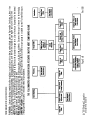
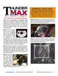
Performer Q-Jet Carburetors for Thermo-Quad Applications
Catalog #1905
for non-computer controlled 1972-1985 Chrysler 360, 400 & 440 V8s
PostScript Picture
(Edelbrock B/W Logo.eps)
INSTALLATION INSTRUCTIONS
PLEASE study these instructions carefully before installing your new carburetor. If you have any questions or problems,
please call our Carburetor Technical Hotline at: (800) 416-8628 or e-mail us at [email protected].
DESCRIPTION
The Edelbrock Performer Q-Jet Carburetor for Thermo-Quad applications is a high quality, all new carburetor designed to
replace the original equipment Thermo-Quad that came stock on 360, 400 and 440 Chrysler engines in trucks and
motorhomes from 1972 to 1985. This Edelbrock carburetor features all-metal construction for no leaks and no hassles. It
includes an electric choke along with a 3/4" 4-hole spacer, throttle lever adapter and fuel line adapter for an easy
installation. These carburetors are street legal parts when used on the applications for which they are listed.
Edelbrock Performer Q-Jet Carburetors for Thermo-Quad applications are compatible with all OEM linkage and components
for the years listed, and will fit stock intake manifolds. For best performance, they may be used with the matching
Performer or Performer EGR intake manifold for those who wish to use a new stock replacement carburetor.
Caution: Check hood clearance due to additional carburetor spacer height.
IMPORTANT NOTES
Before installation of your new carburetor, you must do the following:
1.
Replace fuel filter. Dirt found in carburetor voids warranty.
2.
Check and replace the air filter if necessary.
3.
Check PCV valve and replace if clogged.
4.
Check all hoses for leaks or cracks and replace if necessary.
5.
Check fuel pump for proper operation and replace if necessary.
6.
Check the intake manifold and cylinder head gaskets for leaks and replace if necessary.
7.
Check the ignition system: clean and gap or replace spark plugs, plug wires, and adjust ignition timing.
8.
Check the vacuum line routing from your original carburetor to determine if each line is “timed vacuum”
or “manifold vacuum”. Consult factory manual or underhood vacuum diagram if necessary to determine
vacuum line routing on new carburetor.
9.
Suggested Procedure: With engine fully warmed up, remove vacuum lines from carburetor one at a time
and place your finger over port to feel for vacuum. Timed vacuum ports have little or no vacuum at idle;
manifold vacuum ports have full vacuum at idle.
Note that while this carburetor does not appear identical to your old carburetor, it will perform properly on the models it
was cataloged to replace. Main Jet: .073; Metering Rods: Primary-50M, Secondary-DR.
CARBURETOR REMOVAL
1.
Prior to carburetor removal, make sure that engine is cool.
2.
Disconnect negative battery cable from battery.
3.
Remove air cleaner. Be sure to carefully disconnect any hoses from the air cleaner and note their location
for re-installation. You may want to mark them with masking tape for easy reference.
4.
Disconnect throttle linkage, kickdown linkage (certain automatic transmission applications only), cruise
control (if equipped) and any return springs if present. NOTE: Check carefully for the precise location of all
these linkages and return springs. You may want to mark them with masking tape for easy reference.
5.
Disconnect all wires, tubes and hoses from carburetor and note their location. NOTE: There should be a
maximum of one wire to the electric choke and one to the idle compensator solenoid. Any other electrical
wiring attached to your carburetor indicates a computer controlled engine, and Edelbrock Q-Jet carburetors
for Thermo-Quad applications will not function correctly on computer controlled applications.
6.
Carefully remove fuel line from carburetor or fuel filter. Take extreme care not to spill any excess fuel. Place
a rag underneath the fuel line to absorb any spillage that may occur. Certain models require two wrenches
to remove the fuel line; one to hold the fitting on the carburetor and the second to turn the fitting on the
fuel line. Use a tubing wrench to avoid rounding the tube fitting nut.
© 2001 Edelbrock Corporation
Brochure No. 63-0018
Page 1 of 6
Rev. 10/01
CARBURETOR REMOVAL (Continuation)
7.
Remove mounting nuts or bolts and or washers. Be sure to put them where they won't fall into the intake
manifold upon carburetor removal.
8.
Remove carburetor, being careful not to spill any dirt into the intake manifold. Immediately place a clean
rag into the manifold to keep foreign objects out.
9.
Thoroughly remove old mounting gasket and clean mounting surface.
CARBURETOR PREPARATION
1.
Install throttle adapter bracket on throttle arm (see Figure 2).
2.
Place old and new carburetors side by side and transfer any accessories that are needed onto the new
carburetor.
CARBURETOR INSTALLATION
1. Remove rag from intake manifold and install new mounting studs supplied in kit. The two longer studs will go
towards the front. Install new gasket spacer and carburetor base. NOTE: Do not use any cement, glue or
liquid gaskets.
2.
Carefully place new carburetor over studs and onto base gasket.
3.
Install all mounting nuts and washers. Hand-tighten with a short box end wrench, using even increments
alternating between diagonally opposed bolts. CAUTION: Over tightening may break carburetor base.
FUEL LINE CONNECTION
1.
Cut OEM fuel line in the selected location using either a hacksaw or tubing cutter. It is easier to make the
cut if you first remove the fuel line from the vehicle (after marking the place to be cut).
2.
Make sure that you file and remove the burrs from the rough cut end of the steel line. Also be sure to
thoroughly clean out all filings and metal particles from the line.
3.
Install the Edelbrock special brass hose fitting completely over the OEM steel fuel line (see Figure 1) and
securely tighten the compression unit. Use tubing wrenches if possible to avoid rounding the hex nut.
4.
Install brass adapter fitting in carburetor.
5.
Cut the proper length of the fuel hose supplied in this kit to connect the compression fitting to the brass
adapter fitting in the carburetor.
6.
Install one clamp on each end of this hose and securely push the fuel hose onto the compression fitting and
brass adapter fitting in the carburetor. Make certain that the hose is completely installed on each fitting
before tightening the screw-type worm clamp.
CAUTION: Do not over-tighten the clamps or you may cut into the fuel line and cause a leak.
Models with externally mounted fuel filters, install new fuel filter, starting threads by hand to avoid crossing or stripping
threads. Replace any old or cracked hoses with new hoses designed for use with fuel. Note: If externally mounted fuel
filter has 3/8" barbed outlet, that may be used in place of the fuel line compression fitting as an attachment point for the
fuel hose to the carburetor.
Compression Sleeve
Adapter Fitting
To Carburator
Compression Nut
Fuel Filter
CHOKE WIRE INSTALLATION
Electric choke carburetor #1905 requires a 12-volt
lead that is hot only when the ignition is “On”. Use
volt meter to locate suitable source of electric
power. Splice the wire with plastic connector
(supplied) into this connection, then plug connector
into carburetor electric choke. Do not use 12-volt
coil wire.
Hose
Hose Clamp
Fig. # 1
© 2001 Edelbrock Corporation
Brochure No. 63-0018
Original Fuel line
Page 2 of 6
Rev. 10/01
FINISH INSTALLATION
1.
Re-connect throttle linkage, wires, hoses, etc. Your
Edelbrock carburetor may have more vacuum outlets
than the original. Leave the caps on those outlets
which won't be used. It is also required for proper
operation that you bypass the vacuum amplifier and
vacuum reservoir as seen in figure 3 & 4 . The
throttle positioner may also be removed on some
applications.
2.
Re-connect the air cleaner being careful not to overtighten the mounting nut which could damage the
carburetor. Install a new air filter (if needed) and reconnect all hoses.
3.
IMPORTANT NOTE: With engine off make sure
that there is no interference when opening and
closing the throttle. Be sure that there is no binding
or hanging up between idle and wide open throttle
as this could cause the throttle to stick, resulting in
loss of engine speed control.
4.
Re-connect the negative battery cable to the battery.
Fig. # 2
1
2
1
2
12
3
4
3
4
11
5
5
10
10
9
9
8
1.
2.
3.
4.
5.
6.
7
6
Vacu um Amplifier
Vacu um Reserv ior
Carburetor
EGR Valve
PCV Valve
CC EGR Valve
Fig. # 3
8
7.
8.
9.
10.
11.
12.
7
6
Fig. # 4
Dist ributor
ECS Canistor
Caped Same as OEM
To Fu e l Ta n k
Throttle Positioner
Solenoid Delay Valve
SMOG INFORMATION
Regarding the 1905 carburetor that is installed on your Chrysler engine. The original thermoquad carburetor relied on
the vacuum amplifier to operate the EGR Valve. Using the new Edelbrock carburetor, the vacuum amplifier is not needed.
The EGR can be rerouted using the (port “D”) ported vacuum port. The throttle positioner may also be removed since it
is not applicable to the new carburetor. This was how Edelbrock tested the vehicle when they were granted the VC27156
exemption.
CARBURETOR TESTING
1.
NOTE: Be wary of fuel leaks! If a fuel leak occurs, stop immediately and repair the leak. Failure to do so could
result in engine fire and serious injury.
NOTE: The following adjustments can affect vehicle emissions. Laws in your area may govern these emissions.
a.
Set idle adjustments per factory recommendations for your vehicle.
b.
The choke system is pre-set at the factory, however, minor adjustments may be required. Adjust using factory
specifications for your vehicle.
© 2001 Edelbrock Corporation
Brochure No. 63-0018
Page 3 of 6
Rev. 10/01
IDLE MIXTURE ADJUSTMENT
The Edelbrock Performer Q-Jet Carburetor for Thermo-Quad applications has conventional Idle Mixture Screws (IMS) that
provide a leaner Air/Fuel (A/F) ratio when turned clockwise and richer A/F ratio when turned counterclockwise. The idle
air flow is controlled by a conventional screw that opens the primary throttles. The following procedure should be used
to set the idle mixture and speed:
1.
Fully warm engine and ensure choke is fully open.
2.
Install air cleaner.
3.
Set desired speed with the air screw.
4.
Adjust the IMS on one side to get the maximum possible rpm or highest vacuum if you are using a manifold
vacuum gauge. Do not go rich beyond the maximum speed point.
5.
If the procedure above changed the idle speed more than 40 rpm, then re-adjust the idle speed.
6.
Adjust the opposite side of that in Step 4 to get maximum rpm or vacuum.
7.
Reset the speed.
8.
Carefully trim each IMS to again get the maximum idle rpm or manifold vacuum.
9.
Go leaner just enough to get a 20 rpm drop in speed.
10. Reset the speed to the desired rpm.
11. This is a Lean-Best Idle Set. Setting richer than this will not improve idle quality or performance, but could
cause higher hydrocarbon emissions and tend to foul spark plugs.
12. Emission legal carburetor #1905 is supplied with tamper-resistant protective metal caps for idle mixture
screw wells. These covers should be installed following completion of final idle mixture adjustments.
NOTE: Use idle mixture adjustment tool K&D #2776 or equivalent.
WINTER FUEL IDLE SETS
During the winter months (in most parts of the country), the local fuel will be a "winter" blend that is very volatile, as an
assist to cold-engine starting and drivability during warm-up. However, the high volatility has the disadvantage of allowing
excessive vaporization of the fuel if the vehicle is operated in a heated area such as a garage. This can result in problems
in the idle-set procedures since the carburetor's internal vents will allow this excess vapor to be drawn into the throats
and enriches the mixture. The idle will be erratic and not seem to be able to hold a set. To resolve this problem, it is
advisable to perform the final settings outdoors after the vehicle has been stabilized with a drive of several miles.
EDELBROCK Q-JET REBUILD KITS
The Edelbrock Performer Q-Jet Carburetor for Thermo-Quad applications can be rebuilt with the following rebuild kits:
Carburetor Part Number
#1905
Rebuild Kit Part Number
#1921
REPLACEMENT FUEL FILTERS
The Edelbrock Performer Q-Jet Carburetor for Thermo-Quad applications has a replaceable fuel filter element behind the
Fuel Inlet Nut. Replacement filters are available as follows:
Carburetor Part Number
#1905
Fuel Filter Part Number
#1927
IMPORTANT INFORMATION ABOUT YOUR WARRANTY
If you have any problems with installation or performance, do not return to the retailer. Retailer is not authorized to
perform Warranty Service. Instead, call the Edelbrock Carburetor Tech Hotline at 800-416-8628 from 7am - 5:00pm PST
on weekdays. All returns must be accompanied by the original purchase receipt. The warranty period is 90 days for new
carburetors and 30 days for "as-new" (remanufactured) carburetors.
SPECIAL NOTICE
Edelbrock Performer Q-Jet Carburetor for Thermo-Quad Applications is legal for street use on pollutioncontrolled motor vehicles in all 50 states. To assist you with emissions equipment certification, we have included a
fan shroud decal to help testing personnel verify that the carburetor is a legal replacement part for 1985 & earlier Chrysler
360, 400 and 440-equipped vehicles. The adhesive-backed decal should be affixed to your fan shroud next to the existing
emission and engine specification decal. Do not cover your original equipment specification decal with the Edelbrock
Performer Q-Jet Carburetor decal.
© 2001 Edelbrock Corporation
Brochure No. 63-0018
Page 4 of 6
Rev. 10/01
LEGEND
A
B
C
D
E
F
G
H
-
Diverter Port
Choke Pull-down
Fuel Inlet
Exhaust Gas Recalculation (EGR) Port
Idle Mixture Screws
Positive Crankcase Ventilation (PC V) Port
Canister Purge
Distributor Port
I
J
K
L
M
N
O
-
Idle Speed Screw
Accessory Port
Bowl Vent
Hot Air (#1903 only)
Fast Idle Screw
Clean Air (#1903 only)
1/4" N.P.T. (Power Brake Port)
J
B
K
C
H
L
D
M
E
G
F
E
I
Fig. # 5
N
O
A
Fig. # 6
© 2001 Edelbrock Corporation
Brochure No. 63-0018
Page 5 of 6
Rev. 10/01