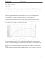
1
BX30 subwoofer Owner’s Manual - and Safety Instructions Preliminary Version 990209 455 490 A EXPLANATION OF GRAPHIC SYMBOLS The lightning flash with arrowhead symbol, within an equilateral triangle, is intended to alert the user to the presence of uninsulated “dangerous voltage” within the product’s enclosure that may be of sufficient magnitude to constitute a risk of electric shock to persons. The exclamation point within an equilateral triangle is intended to alert the user to the presence of important operating and maintenance (servicing) instructions in the literature accompanying the appliance. This product conforms to the following Product Specifications: EN 60065 EN 55103-1 EN 55103-2 EN 60065 (LVD) Safety requirements for mains operated electronic and related apparatus for household and similar general use. Use only in environments where humidity is between 30 and 70%rh and temperature between 5° and 40° C EN 55103-1 (Emission) Electromagnetic compatibility – Product family standard for audio, video, audio-visual and entertainment lightning control apparatus for professional use EN 55103-2 (Immunity) Electromagnetic compatibility – Product family standard for audio, video, audio-visual and entertainment lightning control apparatus for professional use Copyright 1999 by DYNAUDIO ACOUSTICS A/S. All rights reserved. No part of this manual may be reproduced, stored in a retrieval system, or transmitted, in any form or by any means, electronic, mechanical, or otherwise whatsoever, without the prior written permission of DYNAUDIO ACOUSTICS A/S. The information contained in this document is subject to change without notice. Important Safety Instructions Safety Read these instructions before any connection to the apparatus. Please keep these instructions in a convenient place. CAUTION To avoid electric shock, do not open the subwoofer. There are no user-serviceable parts inside. Installation If the BX30 have been stored for a longer period in an environment, where temperature was low or humidity high, we recommend that the BX30 is disconnected for at least three hours before use. Do not operate this apparatus near water. Do not install near any heat sources such as radiators, heat registers, fireplaces, stoves, or other items that produce heat. Do not cover the apparatus. Keep it ventilated, minimum 3 cm all around the cabinet. Power connection Do not defeat the safety purpose of the grounding-type plug. A grounding-type plug has two blades and a third grounding prong. The third prong is provided for your safety. If the provided plug does not fit into the wall outlet, consult an electrician for replacement of the obsolete outlet. Protect the power cord from being stepped on or pinched, particularly at plugs, convenience receptacles, and the point where they exit from the apparatus. Unplug this apparatus during lightning storms or when unused for long periods of time. Attachments Only use attachments/accessories specified by the manufacturer. Servicing Refer all servicing to qualified service personnel. Servicing is required when the apparatus has been damaged in a way such as power supply cord or plug is damaged, liquid has been spilled or objects have fallen into the apparatus, the apparatus has been exposed to rain or moisture, has been dropped, or does not operate normally. Maintenance To prevent fire or shock hazard, clean only with a damp cloth. Never use cleansers or chemicals. Sound pressure level Please note that excessive listening at high sound pressure levels may cause permanent hearing damage. Warning This equipment can produce sound pressure levels in excess of 90 dB(A) Please follow all instructions and heed all warnings CONTENTS SAFETY ................................................................................................................................................ 3 Installation .................................................................................................................................................. 3 Power connection........................................................................................................................................ 3 Attachments ................................................................................................................................................ 3 Servicing ..................................................................................................................................................... 3 Maintenance................................................................................................................................................ 3 Sound pressure level ................................................................................................................................... 3 BX30 OWNER’S MANUAL ................................................................................................................... 5 Unpacking................................................................................................................................................... 5 INTRO .................................................................................................................................................. 5 INLET SECTION .................................................................................................................................... 6 OPERATING PANELS ............................................................................................................................. 7 BX30 PLACEMENT .............................................................................................................................. 9 COOLING ............................................................................................................................................. 9 MOUNTING .......................................................................................................................................... 9 5.1 SYSTEMS ..................................................................................................................................... 11 SOUND CALCULATOR ........................................................................................................................ 12 BX30 TECHNICAL DESCRIPTION ........................................................................................................ 13 System topology........................................................................................................................................ 13 FLOW DIAGRAMS ............................................................................................................................... 14 BOX DATA ......................................................................................................................................... 15 BX30 Owner’s Manual BX30 Owner’s Manual Unpacking Every loudspeaker leaving DYNAUDIO ACOUSTICS A/S has been carefully and thoroughly inspected and tested. When unpacking the subwoofer, be sure to check if any physical damage has occurred to the subwoofer due to shipping. In case of damage, please contact the selling dealer immediately. When unpacking the subwoofer, verify that the voltage switch is positioned according to area voltage requirements. Intro The BX30 is a sophisticated and versatile low frequency monitor speaker, which satisfies all the demands of the recording and postproduction facilities. As a stand-alone unit it can be used to provide the sub bass channel of a 5.1 multi speaker system. It can be used as the bass-extension-section of a small full range monitor, in single mono, dual stereo or multiple applications, where a large amount of low frequency energy is required. The BX30 features an innovative electro-acoustic system which optimises bass output power for the music spectrum, giving an advantage of up to 18 dB over conventional bass reflex designs. Figure 1. The BX30 driver has a –6 dB point at 17 Hz, which results in superb reproduction of the most demanding material. An electronic filter limits the response to 22 Hz in order to prevent large excursion by sub sonic signals and rumble. This filter can be removed when the BX30 is used for reference listening purposes. This is a factory modification, which must be ordered through an authorised agent. A single BX30 is a perfect match to any of the smaller dynaudio acoustics monitors, such as the BM5, BM6, BM6A or M1. The integrated 95 Hz high-pass crossover combined with the variable level and phase adjustment allows perfect matching in any position, giving complete freedom of movement and placement of the BX30; very useful in confined spaces! Two BX30s will be more than a match for the BM15A and BM15, while four will rival the output of very large monitor systems; the BX30 can, thanks to its flexibility, grow with your requirements and give a lifetime of service. 5 BX30 Owner’s Manual Inlet section Figure 2. AC inlet AC inlet Power switch This is a grounding-type plug. Do not connect to a convenient AC outlet on a sound system or non-grounding AC outlet. 0: 1: There is voltage on the amplifier. The Protection LED lights up, red. Voltage switch 115/230: The amplifier’s power supply can be used with various voltages, 115/230 V ~, and frequencies, 50/60 Hz. The voltage selector switch on the back panel of the subwoofer shall be positioned according to the required voltage in your area. The manufacturer fixes the setting prior to shipping. Caution Do not try to alter the voltage setting, as doing so will result in a blown fuse. Wrong settings may result in damaged electronics. Fuse-drawer The main fuse for the subwoofer is located in the Fuse-drawer. Replace For continued protection against risk of fire, replace only with same type of fuse. 115 V: 230 V: 6 8 A / 125 V Slow-blow 4 A / 250 V Slow-blow BX30 Owner’s Manual Operating panels Figure 3. Subwoofer control panel LED Limiter: Lights up when the limiter circuits start protecting the woofer. The limiter does not affect the signals on the XLR OUT. Detect: When the input signal is above – 20 dB it lights green. If the line signal increases to 0 dB it turns red. The protection circuit also measures signal levels inside the subwoofer amplifier. If the level calibration is turned clockwise and the signal in one of the measuring point surpass –20 dB. Protection: Switch on the subwoofer, and the LED turns red, and for the next 5 seconds the protection circuit checks the amplifier. When everything is all right, the protection circuits switch the signal- and speaker relays on. LEVEL Calibration: Adjustment of the subwoofer level. Sensitivity: Level attenuation of input signal. –10 dBm consumer level signal +4 dBm pro level signal Mute for muting the subwoofer. The signal on XLR OUT remains. PHASE Calibration: Changes the phase alignment IN versus subwoofer. Polarity: Invert the IN proportion subwoofer phase. CROSSOVER Low Pass: Changes the crossover frequency subwoofer itself. To fit the BX30 to your main speakers. 7 BX30 Owner’s Manual Figure 4. Output control and connectors CROSSOVER High Pass: Changes round the OUT line signals between : Direct: The signal on XLR IN connectors is directed to the XLR OUT. 95 Hz: The signal on XLR IN runs through a 95 Hz high pass filter, before it is send to the XLR OUT. IN L and R : Balanced line signal input. Pin 1 : Ground Pin 2 : Non inverted (hot) Pin 3 : Inverted (cold) OUT L and R: Balanced line signal output. Pin 1 : Ground Pin 2 : Non inverted (hot) Pin 3 : Inverted (cold) If CROSSOVER High Pass is set on 95 Hz and the BX30 is turned off, the relays in the amplifier will change and thereby the OUT signal will disappear. 8 BX30 Owner’s Manual BX30 Placement Single Unit (Stereo) The correct location and phase alignment of the BX30 is essential to achieve accurate performance with any given system. The best results are usually achieved with the BX30 floor standing and at the same distance from the listening position as the main speakers. The unit should be placed at the centre point of a line between the main speakers if used as part of a stereo system. The polarity and phase can be adjusted so that there is the maximum cut in bass at 95 Hz when the unit is switched ‘out of phase’. This should ensure the optimum coupling with the main speakers when ‘in phase’. Double Units (Stereo) The optimum stereo performance will be achieved with one BX30 directly beneath each main speaker. This will ensure correct panning and image location of signals when mixing. If performance is affected by the presence of a solid console or equipment furniture, it may be necessary to place the BX30 units at the same level as the main speakers in which case suitable, mechanically adequate stands should be employed. In any event the BX30s should always be placed equidistant to the mixing position in order to avoid phase cancellations. Single Low Frequency Effects Channel (.1) In this mode the BX30 will reproduce only the low frequency content of a discrete multi channel format and the positioning is usually asymmetrical to the room. This is done to avoid direct coupling to standing waves which results in better frequency response. The internal filter should be set to 120 Hz for film mixing or as required by the medium being used. Several BX30 units may be daisy chained using the input and output XLR connectors. Large Active Systems The BX30 can be used as part of a large sound system to handle bass frequencies up to 120 Hz. The phase adjustment allows combination with any mid range device and the integrated signal and power management makes the BX30 suitable for club and sound system installations. It is also suitable for mobile use but it should not be used outdoors or anywhere prone to damp or moisture, for electrical safety reasons. The cabinet is designed for free standing or stand mounting; flying or rigging will require a suitable cradle or full supporting bracket. No fixing should be made directly to the MDF panels or rear electronics panel. Cooling The BX30 has full logic thermal control, which will shut the amplifier down in the event of the inner heat sink reaching 60 degrees Celsius. Always allow sufficient air flow, around the rear panel, especially if the unit is mounted in a front wall baffle or similar enclosure. Under normal circumstances the BX30 should not be mounted with the heat sink fins horizontal, as this will impede convection cooling. Mounting Under some conditions it may be desirable to place the BX30 on anti vibration mounts so as avoid direct transmission to a floor or shelf unit. Special damping units may be ordered from your dynaudio acoustics agent who will facilitate this without compromising bass performance. Placing the unit on soft foam or carpet may reduce audible buzzing or vibration. The design of the amplifier lead to the possibility of rotating the amplifier to horizontal or vertical. Disconnect the BX30, then remove the eight fixing screws. Lift the amplifier carefully out of the mounting hole. Then rotate it in the direction which suits you. Place it again and mount the eight fixing screws. 9 BX30 Owner’s Manual Figure 5. Shows the standard 1/3 octave response in active bass extension mode with the crossover pre set to 95 Hz. The response offers a seamless match to any high quality monitor system but it is particularly well suited to smaller models with limited bass output capability. Figure 6. The flexibility of switching low pass and match high pass x-overs means the BX30 can be matched to any system with ease and accuracy. Figure 7. The impulse response of the BX30 is almost perfect for a two octave, 100 Hz band pass filter. The impulse response Figure 7 shows the superior transient response of direct radiating systems compared to narrow resonant cavities and chambers. 10 BX30 Owner’s Manual 5.1 Systems Dolby AC3 format. The specification for each channel is strictly defined and the BX30 conforms carefully and accurately to that standard. The agreed sound level capability for the sub bass channel in film theatres is 115 dB in any one-octave band, in any seat. The BX30 can deliver this output with clean, undistorted power, which is equally suited to small rooms, or in multiple (modular) formats in much larger spaces. Our design chart gives SPL predictions for different rooms. Please note these are narrow band or single frequency predictions, not broad band levels which are much higher. For example a single BX30 will produce 112 dB at 63 Hz at one metre, enough to match nearly all near-field monitors, while eight units can satisfy the requirement for THX theatres of 1000 cubic metres at a distance of 10 metres. By comparison the Dolby requirement for calibrated 5.1 systems is only 105 dB and so the BX30 is well equipped to deal with the future demands of digital multi channel audio, especially in the professional dubbing theatre. 11 BX30 Owner’s Manual Sound Calculator ONE BX30 AT VARYING DISTANCE D FOR 100WRMS POWER Freq. L W H Lw(1W) Lw(Rqd) EPR Q D S V 63 63 63 63 63 63 63 20 20 20 20 20 20 20 10 10 10 10 10 10 10 5 5 5 5 5 5 5 100 100 100 100 100 100 100 120 120 120 120 120 120 120 100 100 100 100 100 100 100 2 1,0 700 2 2,0 700 2 3,0 700 2 4,0 700 2 8,0 700 2 12,0 700 2 16,0 700 1000 1000 1000 1000 1000 1000 1000 a T60 Lp calc Dc 0,4 0,4 0,4 0,4 0,4 0,4 0,4 1 TO 8 BX30 UNITS WITH 1, 10 AND 100W AMP POWER EACH L W H BX30 Lw EPR Q D S V a 20 20 20 20 20 20 20 20 20 20 20 20 L W H Lw Q D EPR 10 10 10 10 10 10 10 10 10 10 10 10 5 5 5 5 5 5 5 5 5 5 5 5 1 1 1 2 2 2 4 4 4 8 8 8 100 110 120 103 113 123 106 116 126 109 119 129 1 10 100 1 10 100 1 10 100 1 10 100 2 2 2 4 4 4 8 8 8 16 16 16 length width height sound power of source speaker directivity index distance to point of measurement electronic power required (amplifier) 1000 1000 1000 1000 1000 1000 1000 1000 1000 1000 1000 1000 0,50 0,50 0,50 0,50 0,50 0,50 0,50 112 107 104 103 101 100 100 3,21 3,21 3,21 3,21 3,21 3,21 3,21 T60 Lp calc Dc 10,0 10,0 10,0 10,0 10,0 10,0 10,0 10,0 10,0 10,0 10,0 10,0 700 700 700 700 700 700 700 700 700 700 700 700 0,4 0,4 0,4 0,4 0,4 0,4 0,4 0,4 0,4 0,4 0,4 0,4 0,50 0,50 0,50 0,50 0,50 0,50 0,50 0,50 0,50 0,50 0,50 0,50 S V a Sa T60 Lp Dc room surface area room volume average absorption total absorption reverb decay time sound pressure at D critical distance Ld=Lr 81 91 101 84 94 104 88 98 108 93 103 113 3,21 3,21 3,21 4,54 4,54 4,54 6,42 6,42 6,42 9,08 9,08 9,08 BX30 Sound Calculator 120 power and Spl 100 80 EPR 60 Lp calc 40 20 0 1 1 1 2 2 2 No. of BX30 12 4 4 4 8 8 8 BX30 Owner’s Manual BX30 Technical description System topology The BX30 is fully active with a sophisticated signal management system. The following features are provided as standard. Dual inputs and outputs fully balanced with automatic bypass in the event of power loss. The outputs are buffered and filtered with a 24 dB/ octave high pass network which forms a perfect 24th order crossover (Linkwitz-Riley) when the BX30 is set at 95 Hz Low Pass mode. A direct through switch is also provided for multiple BX30 linking. • All inputs and outputs are relay switched for full protection of system. There is a voltage protection limiter on each input to protect the balanced line level amplifiers. • A full logic management and protection system controls all switching functions with LED indication of fault conditions. • Switchable –10 dB, +4 dB or mute gain with level control. • Three precision low pass networks, calibrated to meet international standards; • 80 Hz for critical listening applications using high quality small monitors. • 95 Hz for most subwoofer applications in stereo or part of a multi channel system. • 120 Hz for full 5.1 systems requiring a separate low frequency effects channel. This mode is designed to meet Dolby, DTS and THX criteria for theatres. • Additionally there is an internal spectrum equaliser and subsonic filter (17 Hz) to ensure optimum sensitivity and maximum output from 20 Hz to the cut off frequency. • Full 360 degrees of phase adjustment allows room positioning and alignment for optimum summing with a main or satellite speaker. This promotes mutual coupling of multi speaker systems for perfectly solid imaging. • VCA controlled power limiting ensures overload conditions cannot occur. Driver protection is achieved without compression and misleading changes in the sound spectrum. A relay offers instant protection of the driver in a condition of fault or overload. We believe the BX30 is the most advanced low frequency speaker system available. It can work alone or as part of a larger modular system. The 140 W power module is an extremely efficient unit with virtually no quiescent current. The unit can be operated indefinitely in standby mode. Distortion is negligible under normal operating conditions. 13 BX30 Owner’s Manual Flow diagrams IN XLR Input relay Passiv limiter High pass 95 Hz Line receiver Line driver Output relay Output switch L+ 24 dB/oct L+ Left Left OUT XLR Left Left L- L- b b R+ 24 dB/oct R- Right Right Right Right R- R+ b b Buffer Low pass 24 dB/oct 80 Hz Fix level Left Temperature sensor +4 dBm -10 dBm Mute d Level 24 dB/oct 95 Hz h a 60° f e 24 dB/oct 120 Hz Right = also adjustable with a tool Limiter Equalizer Subsonic Phase 0°-180° c Phase +180° Power Amplifier Speaker Speaker relay 24 dB/oct 10 Hz a VCA g b Figure 8. Flowchart preamplifier Comparator V++ ±10% Timer Reset V-- ±10% 0 = fault AND 0 = fault VCC ±5% 3 seconds 0 = fault 0 = fault VEE ±5% 1 = no fault 0 = fault DC at amplifier g Red Green Protection indicator 0 = fault Front of cabinet Temperature > 60° b h Startup 0 = fault Comparator Timer attack 3s hold 10s Input level right d OR Comparator Red; input overload Input level left VU indicator e Green; input Bass level f Front of cabinet Limiter indicator Buffer Comparator = also adjustable with a tool Limiter active c Red; limiting Figure 9. Flowchart protection circuit 14 OR BX30 Owner’s Manual Box data Power Amplifier : collector coupled quasi complementary BJT Phase Shift : 20-150 Hz, variable Frequency Response : +/- 3 dB Internal cabinet volume : inner Bass Principle : reflex Weight : net Dimensions : w×h×d Crossover : Linkwitz-Riley crossover frequencies input output 140 W 0-180 ° 17-80/95/120 Hz 76 litres 29,9 kg 41 × 619 × 547 Mm 80, 95, 120 Hz crossover slope 12 dB/Oct crossover frequencies 95 Hz crossover slope 12 dB/Oct Connections : input output Impedance : input output Woofer : 30 cm polypropylene cone 100 mm pure aluminium wire voice coil Cabinet : front baffle 22 mm MDF cabinet 22 mm chip board XLR female 3 pole XLR male 3 pole 20 kΩ 50 Ω internal bracing structure 15