1
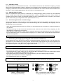
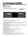
POWER AMPLIFIER DPA 4120 / DPA 4140
BEDIENUNGSANLEITUNG
OWNER'S MANUAL
MODE D'EMPLOI
DPA 4140
4 0 0 WATT S P OW E R A M PL I FI E R
CLIP
TEST
0dB
-13dB
READY
STANDBY
GROUND
FAULT
PROTECT
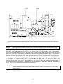
Leistungsmerkmale
Leistungsverstärker mit 200 W oder 400 W Ausgangsleistung nach IEC 283-3
19“ - Chassis (3 HE) ausgestattet mit folgenden Funktionen:
x Netz-Betrieb 115/230V AC und Notstrom-Betrieb 24V DC
x Endstufe DPA 4120 mit 200 W oder DPA 4140 mit 400 W Ausgangsleistung, leerlaufsicher und kurzschlußfest
x Ausgangsübertrager für symmetrisch, erdfreie 100 V Lautsprechernetze, wahlweise 70 V, 50 V oder
4 Ohm für niederohmigen Betrieb
x optionale Input Module:
INPUT MODUL für Standard Anwendungen mit Pegelsteller, elektronisch symm. Eingang und MONITOR -Ausgang optional mit Übertager oder
REMOTE MODUL für Steuerung und Überwachung mit PROMATRIX System, elektron. Pegelsteller, elektronisch symm. Eingang und MONITOR - Ausgang optional mit Übertager
x integriertes Standby-Netzteil
x Netz-Funktionsschalter POWER
x Groundlift-Schalter
x Ferneinschaltung für Netz- und Batteriebetrieb mit Einschaltstrombegrenzung
x Einschaltgeräuschunterdrückung
x Status-LED-Anzeigen für Betrieb (READY), STANDBY, Übertemperatur (PROTECT) und
Erdschluß (GROUND FAULT) am Leistungsausgang
x Störungsmeldung nach IEC 849
x Prüftaste TEST für Anlagen mit Havarieumschaltung bzw. RESET für Erdschluß
x LED-Aussteuerungskontrolle von -13 dB bis 0dB und CLIP
x eingebaute Einzelruf- und Pflichtempfangsrelais
x aktive, temperaturgesteuerte Lüftung
x Modul für Pilotton-Überwachung und Erdschluß-Überwachung nach DIN/VDE 0800 (optional)
Der Nachrüstsatz NRS 90208 (Eingangs-Übertrager) ist im Eingangs-Modul NRS 90222 ab Serien Nr. 10461
und im Eingangs-Modul NRS 90225 ab Serien Nr. 12339 eingebaut
:,&+7,*(6,&+(5+(,76+,1:(,6(
'DV%OLW]V\PEROLQQHUKDOEHLQHVJOHLFKVHLWLJHQ'UHL
HFNVVROOGHQ$QZHQGHUDXIQLFKWLVROLHUWH/HLWXQJHQ
XQG.RQWDNWHLP*HUlWHLQQHUHQKLQZHLVHQDQGHQHQ
KRKH 6SDQQXQJHQ DQOLHJHQ GLH LP )DOO HLQHU
%HUKUXQJ ]X OHEHQVJHIlKUOLFKHQ 6WURPVFKOlJHQ
IKUHQN|QQHQ
'DV $XVUXIH]HLFKHQ LQQHUKDOE HLQHV JOHLFKVHLWLJHQ
'UHLHFNVVROOGHQ$QZHQGHUDXIZLFKWLJH%HGLHQXQJV
VRZLH 6HUYLFHKLQZHLVH LQ GHU ]XP *HUlW JHK|U
HQGHQ/LWHUDWXUDXIPHUNVDPPDFKHQ
/HVHQ6LHGLHVH+LQZHLVH
+HEHQ6LHGLHVH+LQZHLVHDXI
%HDFKWHQ6LHDOOH:DUQXQJHQ
5LFKWHQ6LHVLFKQDFKGHQ$QZHLVXQJHQ
%HWUHLEHQ6LHGDV*HUlWQLFKWLQXQPLWWHOEDUHU1lKHYRQ:DVVHU
9HUZHQGHQ6LH]XP5HLQLJHQGHV*HUlWHVDXVVFKOLHOLFKHLQWURFNHQHV7XFK
9HUGHFNHQ6LHNHLQH/IWXQJVVFKOLW]H%HDFKWHQ6LHEHLGHU,QVWDOODWLRQGHV*HUlWHVVWHWVGLHHQWVSUHFKHQGHQ
+LQZHLVHGHV+HUVWHOOHUV
9HUPHLGHQ6LHGLH,QVWDOODWLRQGHV*HUlWHVLQGHU1lKHYRQ+HL]N|USHUQ:lUPHVSHLFKHUQgIHQRGHUDQGHUHU
:lUPHTXHOOHQ
$FKWXQJ*HUlWQXUDQ1HW]VWHFNGRVHPLW6FKXW]OHLWHUDQVFKOXVVEHWUHLEHQ6HW]HQ6LHGLH)XQNWLRQGHV
6FKXW]OHLWHUDQVFKOXVVHVGHVPLWJHOLHIHUWHQ1HW]DQVFKOXVVNDEHOVQLFKWDXHU.UDIW6ROOWHGHU6WHFNHUGHV
PLWJHOLHIHUWHQ.DEHOVQLFKWLQ,KUH1HW]VWHFNGRVHSDVVHQVHW]HQ6LHVLFKPLW,KUHP(OHNWULNHULQ9HUELQGXQJ
6RUJHQ6LHGDIUGDVVGDV1HW]NDEHOQLFKWEHWUHWHQZLUG6FKW]HQ6LHGDV1HW]NDEHOYRU4XHWVFKXQJHQ
LQVEHVRQGHUHDP*HUlWHVWHFNHUXQGDP1HW]VWHFNHU
9HUZHQGHQ6LHPLWGHP*HUlWDXVVFKOLHOLFK=XEHK|U(UZHLWHUXQJHQGLHYRP+HUVWHOOHUKLHU]XYRUJHVHKHQVLQG
=LHKHQ6LHEHL%OLW]VFKODJJHIDKURGHUEHLOlQJHUHP1LFKWJHEUDXFKGHQ1HW]VWHFNHU
hEHUODVVHQ6LHVlPWOLFKH6HUYLFHDUEHLWHQXQG5HSDUDWXUHQHLQHPDXVJHELOGHWHQ.XQGHQGLHQVWWHFKQLNHU
6HUYLFHDUEHLWHQVLQGQRWZHQGLJVREDOGGDV*HUlWDXILUJHQGHLQH:HLVHEHVFKlGLJWZXUGHZLH]%HLQH
%HVFKlGLJXQJGHV1HW]NDEHOVRGHUGHV1HW]VWHFNHUVZHQQHLQH)OVVLJNHLWLQGDV*HUlWJHVFKWWHWZXUGHRGHUHLQ
*HJHQVWDQGLQGDV*HUlWJHIDOOHQLVWZHQQGDV*HUlW5HJHQRGHU)HXFKWLJNHLWDXVJHVHW]WZXUGHRGHUZHQQHVQLFKW
QRUPDODUEHLWHWRGHUIDOOHQJHODVVHQZXUGH
6WHOOHQ6LHELWWHVLFKHUGDVVNHLQ7URSIRGHU6SULW]ZDVVHULQV*HUlWHLQQHUHHLQGULQJHQNDQQ6WHOOHQ6LHNHLQHPLW
)OVVLJNHLWHQJHIOOWHQ2EMHNWHZLH9DVHQRGHU7ULQNJHIlVVHDXIGDV*HUlW
8PGDV*HUlWNRPSOHWWVSDQQXQJVIUHL]XVFKDOWHQPXVVGHU1HW]VWHFNHUJH]RJHQZHUGHQ
%HLP(LQEDXGHV*HUlWHVLVW]XEHDFKWHQGDVVGHU1HW]VWHFNHUOHLFKW]XJlQJOLFKEOHLEW
(QWVRUJXQJYRQJHEUDXFKWHQHOHNWULVFKHQXQGHOHNWURQLVFKHQ*HUlWHQ$Q]XZHQGHQLQGHQ/lQGHUQGHU
(XURSlLVFKHQ8QLRQXQGDQGHUHQHXURSlLVFKHQ/lQGHUQPLWHLQHPVHSDUDWHQ6DPPHOV\VWHPIUGLHVH
*HUlWH'DV6\PERODXIGHP3URGXNWRGHUVHLQHU9HUSDFNXQJZHLVWGDUDXIKLQGDVVGLHVHV3URGXNWQLFKW
DOVQRUPDOHU+DXVKDOWVDEIDOO]XEHKDQGHOQLVWVRQGHUQEHLHLQHP7HOH[+lQGOHUDEJHJHEHQZHUGHQPXVV
:,&+7,*(6(59,&(+,1:(,6(
$&+781*
'LHVH6HUYLFHKLQZHLVHVLQGDXVVFKOLHVVOLFKIUTXDOL¿]LHUWHV6HUYLFHSHUVRQDOYRUJHVHKHQ
8P GLH *HIDKU HLQHV HOHNWULVFKHQ 6FKODJHV ]X YHUPHLGHQ IKUHQ 6LH NHLQH :DUWXQJVDUEHLWHQ GXUFK
GLH QLFKW LQ GHU %HGLHQXQJVDQOHLWXQJ EHVFKULHEHQ VLQG DXVVHU 6LH VLQG KLHUIU TXDOL¿]LHUW hEHUODVVHQ
6LHVlPWOLFKH6HUYLFHDUEHLWHQXQG5HSDUDWXUHQHLQHPDXVJHELOGHWHQ.XQGHQGLHQVWWHFKQLNHU
%HL5HSDUDWXUDUEHLWHQLP*HUlWVLQGGLH6LFKHUKHLWVEHVWLPPXQJHQQDFK(19'(HLQ]XKDOWHQ
%HLDOOHQ$UEHLWHQEHLGHQHQGDVJH|IIQHWH*HUlWPLW1HW]VSDQQXQJYHUEXQGHQLVWXQGEHWULHEHQZLUGLVWHLQ1HW]
WUHQQWUDQVIRUPDWRU]XYHUZHQGHQ
9RUHLQHP8PEDXPLW1DFKUVWVlW]HQ8PVFKDOWXQJGHU1HW]VSDQQXQJRGHUVRQVWLJHQ0RGL¿NDWLRQHQLVWGDV*HUlW
VWURPORV]XVFKDOWHQ
'LH0LQGHVWDEVWlQGH]ZLVFKHQQHW]VSDQQXQJVIKUHQGHQ7HLOHQXQGEHUKUEDUHQ0HWDOOWHLOHQ
0HWDOOJHKlXVHE]Z]ZLVFKHQGHQ1HW]SROHQEHWUDJHQPPXQGVLQGXQEHGLQJWHLQ]XKDOWHQ
'LH0LQGHVWDEVWlQGH]ZLVFKHQQHW]VSDQQXQJVIKUHQGHQ7HLOHQXQG6FKDOWXQJVWHLOHQGLHQLFKWPLWGHP1HW]
YHUEXQGHQVLQGVHNXQGlUEHWUDJHQPPXQGVLQGXQEHGLQJWHLQ]XKDOWHQ
6SH]LHOOH%DXWHLOHGLHLP6WURPODXISODQPLWGHP6LFKHUKHLWVV\PEROJHNHQQ]HLFKQHWVLQG1RWHGUIHQQXUGXUFK
2ULJLQDOWHLOHHUVHW]WZHUGHQ
(LJHQPlFKWLJH6FKDOWXQJVlQGHUXQJHQGUIHQQLFKWYRUJHQRPPHQZHUGHQ
'LHDP5HSDUDWXURUWJOWLJHQ6FKXW]EHVWLPPXQJHQGHU%HUXIVJHQRVVHQVFKDIWHQVLQGHLQ]XKDOWHQ+LHU]XJHK|UW
DXFKGLH%HVFKDIIHQKHLWGHV$UEHLWVSODW]HV
'LH9RUVFKULIWHQLP8PJDQJPLW026%DXWHLOHQVLQG]XEHDFKWHQ
127(
6$)(7<&20321(170867%(5(3/$&('%<25,*,1$/3$57
2
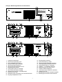
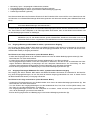
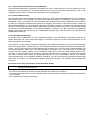
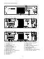
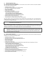
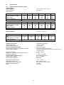
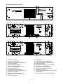
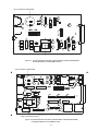
Anzeigen, Bedienungselemente und Anschlüsse
1 2
DPA 4140
40 0 WATT S PO WER A MPLI FI ER
TEST
3
READY
STANDBY
GROUND
FAULT
4
PROTECT
CLIP
0 dB
-13 dB
5
7 6
8
A
9
10
A
11
T4A FOR 230V
T8A FOR 115V
POWER
12
NO USER SERVICEABLE PARTS INSIDE. REFER SERVICING
TO QUALIFIED SERVICE PERSONNEL.
VOLTAGE
SELECTOR
115V
230V
B
13
A
DPA 4140
121629
AC MAINS INPUT
115V /230V AC 50-60 Hz
INPUT
14
THRU
15
MADE IN GERMANY
CAUTION: FOR CONTINUED PROTECTION AGAINST RISK OF FIRE
REPLACE WITH SAME TYPE AND VALUE FUSE INDICATED.
ATTENTION: REMPLACER PAR UN FUSIBLE DE MEME TYPE
COMME INDIQUE.
B
CAUTION
A
ADDRESS
RISK OF ELECTRIC SHOCK
DO NOT OPEN
3
2
1
OUTPUT
VOLTAGE
WARNING: TO REDUCE THE RISK OF FIRE OR ELECTRIC SHOCK,
CIRCUIT TO
CHASSIS SWITCH
A
9
VOR ÖFFNEN DES GERÄTES NETZSTECKER ZIEHEN
19
10
A
18
11
T4A FOR 230V
T8A FOR 115V
POWER
7
8
9
16
POWER OUTPUT
GROUNDED
UNGROUNDED
20
10
REMOTE
CONTROL
AVIS: RISQUE DE CHOC ELECTRIQUE. NE PAS OUVRIR.
+
0
LEVEL
DO NOT EXPOSE THIS APPLIANCE TO RAIN OR MOISTURE.
DC INPUT 24V
4 5 6
12
VOLTAGE
SELECTOR
115V
230V
1 2 3 4 5
90225
17
B
15
A
NO USER SERVICEABLE PARTS INSIDE. REFER SERVICING
TO QUALIFIED SERVICE PERSONNEL.
DPA 4140
B
INPUT
14
121629
AC MAINS INPUT
115V /230V AC 50-60 Hz
ADDRESS
MADE IN GERMANY
A
CAUTION: FOR CONTINUED PROTECTION AGAINST RISK OF FIRE
REPLACE WITH SAME TYPE AND VALUE FUSE INDICATED.
ATTENTION: REMPLACER PAR UN FUSIBLE DE MEME TYPE
B
COMME INDIQUE.
B
CAUTION
ADDRESS
RISK OF ELECTRIC SHOCK
DO NOT OPEN
OUTPUT
VOLTAGE
WARNING: TO REDUCE THE RISK OF FIRE OR ELECTRIC SHOCK,
DO NOT EXPOSE THIS APPLIANCE TO RAIN OR MOISTURE.
21
A
THRU
IN
22
REMOTE
CONTROL
AVIS: RISQUE DE CHOC ELECTRIQUE. NE PAS OUVRIR.
DC INPUT 24V
+
GROUNDED
UNGROUNDED
20
1
2
3
4
5
6
7
8
9
10
11
12
13
CIRCUIT TO
CHASSIS SWITCH
19
POWER OUTPUT
OUT
23
STATUS
VOR ÖFFNEN DES GERÄTES NETZSTECKER ZIEHEN
18
1 2 3 4 5
90222
17
B
14
15
16
17
18
19
20
21
22
23
A
B
Aussteuerungsanzeige
Übersteuerungsanzeige CLIP
Prüf- und Reset-Taste TEST
Bereitschaftsanzeige STANDBY
Störungsanzeige PROTECT
Störungsanzeige GROUND FAULT
Betriebsanzeige READY
Lüftungsöffnungen für Lufteintritt
Netz-Funktionsschalter POWER
Netzanschluß-Stecker AC MAINS INPUT
Netzsicherung FUSE
Netzspannungs-Umschalter VOLTAGE SELECTOR
Eingangs-Pegelsteller LEVEL
3
Eingangs-Buchse INPUT
Durchschleif-Buchse THRU
Steueranschluß REMOTE CONTROL
Leistungsausgang POWER OUTPUT
Lüftungsöffnungen für Luftaustritt
CIRCUIT A TO CHASSIS SWITCH
Batterieanschluß DC INPUT 24V =
Schalter IDENT ADDRESS
Anschlußbuchsen REMOTE CONTROL
Anzeige STATUS
Befestigungsschrauben Netzteil Printplatte
Befestigungsschrauben INPUT MODUL
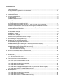
Inhaltsverzeichnis
Leistungsmerkmale........................................................................................................................................ 1
Anzeigen, Bedienungselemente und Anschlüsse ......................................................................................... 3
1.
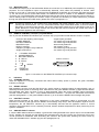
Verwendung .................................................................................................................................................. 5
2.
Installationshinweise ..................................................................................................................................... 5
3.
Vor der Inbetriebnahme ................................................................................................................................ 5
3.1 Netzbetrieb.............................................................................................................................................. 5
3.2 Batteriebetrieb 24V DC ........................................................................................................................... 6
4.
Eingang INPUT .............................................................................................................................................. 6
5.
Ausgänge ....................................................................................................................................................... 7
5.1 Leistungsausgang POWER OUTPUT .................................................................................................... 7
5.2 Leistungsausgang POWER OUTPUT für 100V (70V oder 50V)-Lautsprecher ..................................... 7
5.3 Einzelrufrelais SINGLE CALL und Pflichtempfangsrelais OVERRIDE BYPASS ................................... 7
5.4 Leistungsausgang POWER OUTPUT für niederohmige Lautsprecher.................................................. 7
5.5 Kontrollausgang MONITOR ................................................................................................................... 8
5.6 Steueranschluß REMOTE CONTROL (nur NRS 90225) ....................................................................... 8
6.
Anzeigen ........................................................................................................................................................ 8
6.1 STANDBY-Anzeige................................................................................................................................. 8
6.2 READY Anzeige...................................................................................................................................... 8
6.3 PROTECT Anzeige................................................................................................................................. 8
6.4 GROUND FAULT Anzeige ..................................................................................................................... 8
6.5 Aussteuerungskontrolle und CLIP-Anzeige............................................................................................ 9
7.
Umschaltung der Ausgangsspannung........................................................................................................... 9
8.
Erweiterung des Anwendungsbereiches ..................................................................................................... 10
8.1 Standard Eingangsmodul NRS 90225.................................................................................................. 10
8.2 Remote Modul NRS 90222................................................................................................................... 10
8.3 NRS 90208 Eingangs-Übertrager für erdfrei, symmetrischen Eingang ............................................... 11
8.4 NRS 90227 Ausgangs-Übertrager für erdfrei, symmetrischen Monitor-Ausgang ................................ 11
8.5 NRS 90224 Pilotton & Erdschluß Überwachung .................................................................................. 13
8.5.1 Pilotton-Überwachung................................................................................................................. 13
8.5.2 Erdschluß-Überwachung ............................................................................................................ 13
9.
Einbau in 19"-Gehäuse oder 19“-Gestellschränke ...................................................................................... 16
10.
Groundlift Schalter CIRCUIT A TO CHASSIS SWITCH.............................................................................. 16
11.
Sicherungen ................................................................................................................................................. 16
11.1 Sicherungen in DPA 4120 .................................................................................................................. 16
11.2 Sicherungen in DPA 4140 .................................................................................................................. 16
12.
Technische Daten Leistungsverstärker ....................................................................................................... 20
12.1 DPA 4120 Leistungsverstärker 200 W ............................................................................................... 20
12.2 DPA 4140 Leistungsverstärker 400 W ............................................................................................... 21
13.
Technische Daten Nachrüstsätze................................................................................................................ 22
13.1 NRS 90225 Standard Eingangsmodul................................................................................................ 22
13.2 NRS 90222 Remote Modul................................................................................................................. 22
13.3 NRS 90208 Eingangs-Übertrager für erdfrei, symmetrischen Eingang ............................................. 22
13.4 NRS 90227 Ausgangs-Übertrager für erdfrei, symmetrischen Monitor-Ausgang .............................. 22
13.5 NRS 90224 Pilotton & Erdschluß Überwachung ................................................................................ 22
14.
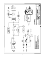
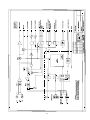
Blockdiagramme .......................................................................................................................................... 67
14.1 Leistungsverstärker DPA 4120 / DPA 4140 ....................................................................................... 67
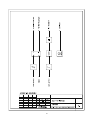
14.2 NRS 90225 Standard Eingangsmodul ............................................................................................... 68
14.3 NRS 90222 Remote Modul................................................................................................................. 69
14.4 NRS 90224 Pilotton & Erdschluß Überwachung ................................................................................ 70
Garantie ....................................................................................................................................................... 72
15.
4
1.
Verwendung
Die Verstärker DPA 4120 und DPA 4140 sind speziell für den leistungssicheren und zuverlässigen Betrieb von PASystemen ausgelegt. DPA 4120 und DPA 4140 sind besonders für Ruf- und Durchsageanlagen, Alarmierungsanlagen und für Musikübertragung in Betrieben, Büro- und Geschäftsräumen, Versammlungs- und Sportstätten,
Schulen und Kirchen, Hotels, Krankenhäusern, Supermärkten, Fahrgastschiffen und andere ähnliche Anwendungen geeignet.
2.
Installationshinweise
Bei der Aufstellung oder Montage des Verstärkers ist darauf zu achten, daß die Luftzufuhr an der Frontseite und
die Entlüftung an der Geräterückseite nicht behindert wird (Einbau in 19"-Gehäuse oder 19“-Gestellschränke siehe
Abschnitt 9).
Zur Einhaltung der EMV Störfestigkeit müssen alle Eingangs-, Ausgangs- und Steuerleitungen außer den Versorgungsleitungen geschirmt verlegt werden. Innerhalb von Metallgehäusen oder Gestellschränken können die Ausgangs- und Steuerleitungen ungeschirmt verlegt werden. Die entsprechenden Schirme sind mit der Gehäuse- oder
Gestellschrank-Erde zu verbinden.
Der Verstärker ist zu schützen vor:
- Tropf- oder Spritzwasser
- direkter Sonnenbestrahlung
- hoher Umgebungstemperatur oder unmittelbarer Einwirkung von Wärmequellen
- hoher Luftfeuchtigkeit
- starken Staubablagerungen
- starken Vibrationen
Wenn der Verstärker direkt von einem kalten an einen warmen Ort gebracht wird, kann sich Feuchtigkeit auf Innenteilen niederschlagen. Das Gerät darf erst in Betrieb genommen werden, wenn sich der Verstärker auf die geänderte Temperatur erwärmt hat (nach etwa einer Stunde).
Sollte ein fester Gegenstand oder Flüssigkeit in das Gehäuse gelangen, trennen Sie sofort die Stromquellen vom
Gerät ab und lassen das Gerät von einer DYNACORD Servicestelle überprüfen, bevor Sie es weiterverwenden.
Zur Reinigung des Gerätes dürfen keine Sprühmittel verwendet werden, da diese dem Gerät schaden und sich
plötzlich entzünden können.
3.
Vor der Inbetriebnahme
Diese Leistungsverstärker können mit unterschiedlichen Eingangsmodulen arbeiten. Für alle herkömmlichen Anwendungen ist das Standard-Eingangsmodul NRS 90225 vorgesehen. Hiermit lassen sich die Verstärker über
Leitung ferneinschalten, mit dem Störungsmelderelais überwachen und über den Monitor-Ausgang abhören. Mit
dem Remote-Control-Modul NRS 90222 sind die Verstärker über eine RS-485 Remote-Schnittstelle mit dem
PROMATRIX Manager DPM 4000 voll fernbedienbar und überwachbar. Das gewünschte Eingangsmodul ist an
der Geräte-Rückseite des Leistungsverstärkers in den Modulschacht einzuschieben und mit den zwei Befestigungsschrauben (B) zu befestigen (siehe Abschnitt 8.1 und 8.2).
3.1
Netzbetrieb
Für normalen Wechselspannungsbetrieb ist das mitgelieferte Netzanschlußkabel an eine 230V oder 115V
50/60Hz Netzsteckdose anzuschließen. Am Gerät ist das Netzanschlußkabel an den 3-poligen Kaltgeräte-Stecker
(10) anzustecken.
Achtung
Das Gerät ist ab Werk auf 230V AC eingestellt. Eine Umschaltung auf 115V AC kann mit dem Spannungswähler (12) vorgenommen werden.
DPA 4120: Für 115V AC Betrieb ist die Netzsicherung (11) durch eine träge 4 Ampere Sicherung
mit dem Aufdruck "T4A" zu ersetzen (siehe Abschnitt 11.1).
DPA 4140: Für 115V AC Betrieb ist die Netzsicherung (11) durch eine träge 8 Ampere Sicherung
mit dem Aufdruck "T8A" zu ersetzen (siehe Abschnitt 11.2).
5
Bei richtigem Anschluß und vorhandener Netz-Spannung leuchtet die grüne STANDBY Anzeige (4). Zum Einschalten des Verstärkers bei Netzbetrieb mit Ferneinschaltung ist an der Stiftleiste REMOTE CONTROL (16) Kontakt 3 POWER REMOTE mit Kontakt 2 - GROUND STANDBY zu verbinden (siehe Abschnitt 5.6).
Für Servicezwecke ist der Netz-Funktionsschalter POWER (9) an der Geräterückseite vorgesehen, mit dem das
Netz-Einschaltrelais überbrückt werden kann. Hiermit kann der Verstärker ohne Ferneinschaltung in Betrieb genommen werden.
Hinweis
Der Netz-Funktionsschalter POWER (9) an der Geräterückseite ist nur für Servicezwecke vorgesehen. Eine Fern-Ausschaltung kann bei eingeschaltetem POWER Schalter nicht vorgenommen
werden.
Die Verstärker DPA 4120 und DPA 4140 haben zur Vermeidung von Einschaltgeräuschen eine Einschaltverzögerung von ca. 3s. Nach Ablauf dieser Zeit leuchtet die grüne READY-Betriebsanzeige und das READYStörungsmelde-Relais schaltet ein, falls kein Fehler vorliegt (siehe Abschnitt 6.2).
3.2
Batteriebetrieb 24V DC
Die Verstärker DPA 4120 und DPA 4140 können wahlweise vom Wechselstromnetz oder von einer externen 24VBatterie gespeist werden. Die Einschaltung der Batterie-Stromversorgung geschieht durch eingebaute Relais.
Der Batterieanschluß ist mit isolierten AMP-Flachsteckhülsen 6.3x0.8 mm an der Geräterückseite (20) vorzunehmen. Der Verstärker ist vor Falschpolung geschützt und im Gerät ist die Plus- und Minusleitung mit je einer Flachsteck-Sicherung abgesichert. Die Sicherungen befinden sich auf der Printplatte 85270 (DPA 4120) bzw. 85268
(DPA 4140) (siehe Abschnitt 11, Bild 10 bzw. Bild 11).
Der Querschnitt der Anschlußleitung zur Batterie soll für DPA 4120 mindestens 1.5 mm² und für DPA 4140 mindestens 2,5 mm² betragen. Die Leitungslänge für einfache Entfernung soll bei diesen Querschnitten nicht größer
als 4.0 m sein (max. Spannungsabfall <1V).
Vorsicht
4.
Die Verstärker DPA 4120 und DPA 4140 dürfen nur mit ungeerdeten Batterien oder Batterien mit
geerdetem Minuspol verwendet werden. Ein Betrieb mit geerdetem Pluspol ist nicht zulässig.
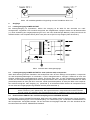
Eingang INPUT
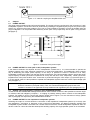
Der Eingang INPUT (14) ist elektronisch symmetrisch mit einer Empfindlichkeit von 775mV = 0dBu für den Anschluß von Steuerverstärkern ausgelegt. Sollen mehrere Endstufen mit dem gleichen Eingangssignal betrieben
werden, kann das Eingangssignal an der Anschlußbuchse THRU (15) für den Betrieb weiterer Endstufen entnommen werden (siehe Bild 1 und Bild 2).
Der Eingang ist vorbereitet für die Nachrüstung eines Eingangsübertragers, für den Fall, daß der Eingang potentialfrei sein muß. In diesem Fall ist der Nachrüstsatz NRS 90208 erforderlich (siehe Abschnitt 8.3).
Bei dem Standard-Eingangsmodul NRS 90225 kann der Eingangspegel mit dem Pegelsteller (13) eingestellt werden. Bei dem Remote-Control-Modul NRS 90222 kann der Eingangspegel mit dem eingebauten elektronischen
Pegelsteller vom PROMATRIX Manager DPM 4000 ferneingestellt werden (siehe PROMATRIX Handbuch).
Bild 1 Anschlüsse der Eingangsbuchsen
6
Bild 2 NF-Verbindungskabel zur Koppelung von zwei Verstärkern DPA 41xx
5.
Ausgänge
5.1
Leistungsausgang POWER OUTPUT
Der Leistungsausgang ist symmetrisch, erdfrei. Der Ausgang ist ab Werk für den Anschluß von 100VLautsprechern vorgesehen. Der Anschluß erfolgt über den mitgelieferten 5-poligen Stecker an der Buchsenleiste
(17). Eine Umstellung der Ausgangsspannung auf 70V, 50V oder niederohmigen Betrieb (4 Ohm) kann durch die
Steckbrücke B411 auf Printplatte 84187 (DPA 4120) bzw. 84175 (DPA 4140) erfolgen (siehe Abschnitt 7).
Bild 3 Anschluß des Leistungsausgangs
5.2
Leistungsausgang POWER OUTPUT für 100V (70V oder 50V) Lautsprecher
Wenn die Entfernung zwischen Verstärker und Lautsprecher mehr als 50 m beträgt, wird empfohlen, Lautsprecher
mit 100V-Anpassungsübertragern zu verwenden, um die Leitungsverluste zu verringern. Hierdurch ist auch eine
einfache Verteilung der Ausgangsleistung möglich. Es können dann max. so viele Lautsprecher angeschlossen
werden, bis die Gesamtleistungsaufnahme des Lautsprechernetzes dem Leistungswert des Verstärkers von 200W
(Anschlußimpedanz 50 Ohm) bei DPA 4120 bzw. 400W (Anschlußimpedanz 25 Ohm) bei DPA 4140 entspricht.
Der Anschluß erfolgt am 100V Ausgang (17) (siehe Bild 3). In besonderen Fällen können die Lautsprecher auch
mit 70V oder 50V Ausgangsspannung betrieben werden (siehe Abschnitt 7).
Vorsicht
5.3
Die Ausgänge an der Anschlußbuchse POWER OUTPUT können im Betrieb berührungsgefährliche
Werte annehmen (>34V Spitzenwert). Die angeschlossenen Lautsprecherkreise sind aus diesem
Grunde gemäß den geltenden Sicherheitsbestimmungen zu installieren (siehe auch Abschnitt 8.5.2).
Einzelrufrelais SINGLE CALL und Pflichtempfangsrelais OVERRIDE BYPASS
In Verbindung mit dem PROMATRIX Manager DPM 4000 oder anderer externer Steuerungen können Einzelrufoder Sammelrufübertragungen auch mit Pflichtempfang, d.h. Überbrückung evtl. vorhandener Lautstärkesteller bei
den Lautsprechern, durchgeführt werden. Für den Anschluß der Ausgänge siehe Bild 3, für den Anschluß der Relais siehe Abschnitt 5.6 bzw. PROMATRIX Handbuch.
7
5.4
Leistungsausgang POWER OUTPUT für niederohmige Lautsprecher
Bei Umschaltung des Ausgangs auf 4 Ohm können niederohmige Lautsprecher (4-16 Ohm) angeschlossen werden (siehe Abschnitt 7 und Bild 3). Wegen der Leitungsverluste soll die Entfernung zwischen Verstärker und Lautsprecher jedoch nicht mehr als etwa 50m betragen. Es ist darauf zu achten, daß die gesamte Lautsprecher-Impedanz von 4 Ohm nicht unterschritten wird und die für den einzelnen Lautsprecher angegebene Leistung nicht
überschritten wird.
5.5
Kontrollausgang MONITOR
An den MONITOR-Ausgang (16) des NRS 90225 kann ein Kontrollverstärker angeschlossen werden. Der Ausgang ist niederohmig und elektronisch symmetrisch, deswegen darf die Länge der angeschlossenen Leitung bis zu
ca. 200 m betragen. Der Anschluß erfolgt an der Stiftleiste REMOTE CONTROL (siehe Bild 4). Bei dem RemoteControl-Modul NRS 90222 befindet sich der MONITOR-Ausgang an der Anschlußbuchse REMOTE CONTROL
(22) und wird vom PROMATRIX Manager DPM 4000 auf den Abhörkanal geschaltet. Der Ausgang ist vorbereitet
für die Nachrüstung eines Ausgangsübertragers, für den Fall, daß der Ausgang potentialfrei sein muß. In diesem
Fall ist der Nachrüstsatz NRS 90227 erforderlich (siehe Abschnitt 8.4).
Hinweis
5.6
Änderungen der Funktion DPA 4120 (ab Ser.Nr. 10011) und DPA 4140 (ab Ser.Nr. 10011) in Verbindung mit dem Eingangsmodul NRS 90225: Zur Unterdrückung von Knackstörungen bleibt der
Monitor-Ausgang stummgeschaltet, solange das READY-Relais nicht gezogen ist. Schaltungsbedingt ist dadurch der Monitor-Ausgang auch bei einem Erdschluß am Hauptausgang stummgeschaltet.
Steueranschluß REMOTE CONTROL (nur NRS 90225)
An der 15-poligen D-Sub-Siftleiste REMOTE CONTROL (16) stehen verschiedene Steuer-Ein-/Ausgänge zur Verfügung:
- Ground der Standby Stromversorgung
- Netzferneinschaltung POWER REMOTE
- Batterieferneinschaltung BATTERY REMOTE
- Kontrollausgang MONITOR
- Meldung Betriebsbereitschaft READY
- Pflichtempfangs-Relais D-RELAY
- Einzelruf-Relais E-RELAY
2
3
4
5
6
7
8
15
9
10
- Minuspol geerdet
- durch Kontakt gegen Masse
- durch Kontakt gegen Masse
- elektronisch symmetrisch
- mit potentialfreiem Kontakt
- durch Kontakt gegen Masse
- durch Kontakt gegen Masse
A STANDBY GROUND
POWER REMOTE
BATTERY REMOTE
D - RELAY
E - RELAY
REMOTE CONTROL
READY
+ MONITOR
- MONITOR
Bild 4 Anschlüsse der REMOTE CONTROL Stiftleiste
6.
Anzeigen
6.1
STANDBY-Anzeige
Bei richtigem Anschluß und vorhandener Netz-Spannung und/oder Batterie-Spannung leuchtet die grüne
STANDBY Anzeige (4).
6.2
READY Anzeige
Die Verstärker DPA 4120 und DPA 4140 haben zur Vermeidung von Einschaltgeräuschen eine Einschaltverzögerung von ca. 3s. Nach Ablauf dieser Zeit leuchtet die grüne READY-Betriebsanzeige (7) und das READYStörungsmelde-Relais schaltet ein, falls kein Fehler vorliegt. Bei Übertemperatur im Netztransformator, in der Endstufe, oder wenn bei eingebautem NRS 90224 der Pilotton-Schwellwert (siehe Abschnitt 8.5.1) unterschritten wird,
leuchtet die grüne READY-Betriebsanzeige (7) nicht und das READY-Störungsmelde-Relais schaltet in Ruhelage.
8
6.3
PROTECT Anzeige
Bei Übertemperatur im Netztransformator oder in der Endstufe leuchtet die rote PROTECT Anzeige (5) und das
READY-Störungsmelde-Relais schaltet in Ruhelage. Nach Abkühlung des Verstärkers erlischt die rote PROTECT
Anzeige (5) automatisch und das Gerät schaltet in den Normalbetrieb. Die Ursache dieses Fehlerzustandes kann
Überlast, zu hohe Umgebungstemperatur oder ein Fehler im Lüftungssystem sein.
6.4
GROUND FAULT Anzeige
Wenn bei eingebautem NRS 90224 ein Erdschluß am Leistungsausgang auftritt, leuchtet die rote GROUND
FAULT Anzeige (6) und das READY-Störungsmelde-Relais schaltet in Ruhelage. Bei diesem Fehler arbeitet der
Verstärker normal weiter. Wenn der Erdschluß beseitigt ist, kann die GROUND FAULT Anzeige (6) durch betätigen der TEST Taste (3) zurückgesetzt werden (siehe Abschnitt 8.5.2).
6.5
Aussteuerungskontrolle und CLIP-Anzeige
Die grüne LED-Anzeige -13dB und 0dB (1) sowie die rote LED-Anzeige CLIP (2) gestattet eine Kontrolle des Ausgangspegels. Dadurch sind Verzerrungen durch Übersteuerung und eine Überlastung des Ausgangs und der
Lautsprecher sicher zu vermeiden.
- Wenn bei Programmspitzen die rote CLIP-LED (2) nur kurz aufleuchtet, ist die maximale, unverzerrte Aussteuerung erreicht.
- Eine Übersteuerung wird durch dauerndes aufleuchten oder blinken der roten CLIP-LED (2) angezeigt, der Eingangspegel ist in diesem Fall zu verringern.
- Wenn die grüne LED-Anzeige (1) nicht oder nur teilweise aufleuchtet und gleichzeitig die rote CLIP-LED blinkt,
liegt eine Überlastung bzw. ein Kurzschluß des Ausgangs vor. In diesem Fall ist die Impedanz der angeschlossenen Last zu überprüfen.
Achtung
7.
Bei normalem Betrieb darf die rote CLIP-LED nur sehr kurz und selten aufleuchten !
Umschaltung der Ausgangsspannung (Nur vom Fachmann auszuführen!)
Die Verstärker DPA 4120 und DPA 4140 können Lautsprechersysteme wahlweise mit 50V, 70V oder 100V Ausgangsspannung oder niederohmig (4 Ohm) speisen. Ab Werk ist die Ausgangsspannung auf 100V eingestellt. Eine
Umschaltung auf 4 Ohm, 50V oder 70V kann duch umstecken der Steckbrücke B411 auf der Endstufen-Printplatte
84187 (DPA 4120) bzw. 84175 (DPA 4140) vorgenommen werden:
Vorsicht
Vor dem Öffnen des Gerätes ist der Netzstecker zu ziehen und eventuell angeschlossene Batterieleitungen sind abzustecken !
- Zum Öffnen des Gerätes ist der Deckel an der Oberseite des Gehäuses zu entfernen.
- Die Steckbrücke B411 (gelbe Leitung) ist von dem Kontakt B407 abzuziehen und auf den gewünschten Kontakt
(siehe Tabelle 1) aufzustecken (siehe Bild 8 bzw. Bild 9).
- Die Codierbrücken S405 und S406 für die Ausgangs Erkennung sind wie in Bild 5 gezeigt zu stecken
(die gesteckte Codierbrücke ist schwarz dargestellt).
- Der Gerätedeckel ist wieder zu befestigen.
Hinweis
Nach der Umschaltung der Ausgangsspannung ist der eingestellte Wert auf der Geräte-Rückwand
in dem vorgesehenen Feld OUTPUT VOLTAGE mit einem wasserfesten Stift einzutragen.
Ausgang
100 V
70 V
50 V
4 OHM
Steckbrücke
B411 auf
B407
B408
B409
B410
Tabelle 1 Steckbrücke B411
für Ausgangs-Umschaltung
Bild 5 Codierbrücken S405 und S406 für
Ausgangs-Erkennung OUTPUT CONFIG
9
Vorsicht
Die Ausgänge an der Anschlußbuchse POWER OUTPUT können im Betrieb berührungsgefährliche
Werte annehmen (>34V Spitzenwert). Die angeschlossenen Lautsprecherkreise sind aus diesem
Grunde gemäß den geltenden Sicherheitsbestimmungen zu installieren (siehe auch Abschnitt 8.5.2).
8.
Erweiterung des Anwendungsbereiches
8.1
Standard Eingangsmodul NRS 90225
Eingangsmodul für die Endstufen DPA 4120 und DPA 4140 als Einschub an der Endstufen-Rückseite, ausgestattet
mit den folgenden Funktionen:
x Eingangs-Buchse XLR mit Verriegelung
x Ausgangs-Buchse XLR zum Durchschleifen des Eingangssignals
x Eingangs-Pegelsteller für Schraubendreher-Betätigung
x Fernschaltung der Netzversorgung ON/OFF
x Fernschaltung der Batterieversorgung ON/OFF
x Steuerung des D- und E-Relais
x Störungsmeldung mit potentialfreiem READY Relais-Kontakt von
- Übertemperatur im Netztransformator
- Übertemperatur der Endstufe
- Ground Fault (optional, nur bei eingebautem NRS 90224)
- Pilotton-Signal (optional, nur bei eingebautem NRS 90224)
x MONITOR - Ausgang elektronisch symm.
x Eingangsübertrager für erdfrei, symmetrischen Eingang optional
x Ausgangsübertrager für erdfrei, symmetrischen Monitor-Ausgang optional
Das Eingangsmodul ist für die Endstufen DPA 4120 und DPA 4140 vorgesehen. Damit können diese Endstufen in
herkömmlicher Technik oder (mit Einschränkungen) vom PROMATRIX Manager DPM 4000 gesteuert und überwacht werden.
Vorsicht
Vor dem Einbau des Eingangsmodul NRS 90225 ist der Netzstecker zu ziehen und eventuell angeschlossene Batterieleitungen sind abzustecken!
Vor dem Einbau des Eingangsmoduls sind die beiden Befestigungsschrauben B an der Geräterückseite zu entfernen. Zum Einbau ist die Leiterplatte in die Führungsschlitze einzusetzen, dann ist das Modul einzuschieben und
mit den Befestigungsschrauben zu befestigen.
Hinweis
8.2
Änderungen der Funktion DPA 4120 (ab Ser.Nr. 10011) und DPA 4140 (ab Ser.Nr. 10011) in Verbindung mit dem Eingangsmodul NRS 90225: Zur Unterdrückung von Knackstörungen bleibt der
Monitor-Ausgang stummgeschaltet, solange das READY-Relais nicht gezogen ist. Schaltungsbedingt ist dadurch der Monitor-Ausgang auch bei einem Erdschluß am Hauptausgang stummgeschaltet.
Remote Modul NRS 90222
Eingangs- und Remote Modul für die Endstufen DPA 4120 und DPA 4140 als Einschub an der EndstufenRückseite, ausgestattet mit den folgenden Funktionen:
x Eingangs-Buchse XLR mit Verriegelung
x Ausgangs-Buchse XLR zum Durchschleifen des Eingangssignals
x Eingangspegel, mit Hilfe eines programmierbaren Audio-Pegelstellers einstellbar
x MUTE (durch Pegelsteller)
x Fernschaltung der Netzversorgung ON/OFF
x Fernschaltung der Batterieversorgung ON/OFF
x Steuerung des D- und E-Relais
x Überwachung und Störungsmeldung durch PROMATRIX Manager DPM 4000 nach IEC 849
- Übertemperatur im Netztransformator
- Übertemperatur der Endstufe
- Ground Fault (optional, nur bei eingebautem NRS 90224)
- Pilotton-Signal (optional, nur bei eingebautem NRS 90224)
- Messung von Ausgangsspannung / -pegel
- Messung von Ausgangsstrom
- Überwachung der angeschlossenen Last durch Strom-Spannungs-Messung
x MONITOR - Ausgang elektronisch symm.
10
x
x
x
x
Monitoring: Input- / Outputsignal auf Monitorbus schalten
Eingangsübertrager für erdfrei, symmetrischen Eingang (optional)
Ausgangsübertrager für erdfrei, symmetrischen Monitor-Ausgang (optional)
Pilottonsignal ON/OFF (optional)
Das Remote Modul dient als Fernsteuer-Einschub für die Endstufen DPA 4120 und DPA 4140. Damit können diese Endstufen vom PROMATRIX Manager DPM 4000 gesteuert und überwacht werden (siehe PROMATRIX Handbuch).
Vorsicht
Vor dem Einbau des Remote Modul NRS 90222 ist der Netzstecker zu ziehen und eventuell angeschlossene Batterieleitungen sind abzustecken !
Vor dem Einbau des Eingangsmoduls sind die beiden Befestigungsschrauben B an der Geräterückseite zu entfernen. Zum Einbau ist die Leiterplatte in die Führungsschlitze einzusetzen, dann ist das Modul einzuschieben und
mit den Befestigungsschrauben zu befestigen.
Hinweis
8.3
Nach dem Einbau des Remote Modul NRS 90222 ist die Adresse mit den zwei Hex-Code-Schaltern
ADDRESS (21) für die Modul-Adresse gemäß PROMATRIX Handbuch einzustellen und auf der
Geräte-Rückwand in dem vorgesehenen Feld ADDRESS mit einem wasserfesten Stift einzutragen.
Eingangs-Übertrager NRS 90208 für erdfrei, symmetrischen Eingang
Der Eingang des INPUT MODUL NRS 90225 und REMOTE MODUL NRS 90222 ist vorbereitet für die Nachrüstung eines Eingangsübertragers, für den Fall, daß der Eingang potentialfrei sein muß. In diesem Fall ist der Nachrüstsatz NRS 90208 pro Eingang erforderlich.
Der Einbau ist wie folgt vorzunehmen (siehe Bild 6 bzw. Bild 7):
- Ausbau des Eingangsmoduls an der Geräterückseite durch lösen der beiden Befestigungsschrauben (B). Das
Modul läßt sich nun leicht herausziehen.
- Vor dem Einbau des Eingangsübertragers sind die Widerstände R1 und R2 zu entfernen.
- Der Eingangsübertrager ist dann so auf der Leiterplatte zu bestücken, daß die auf der Anschlußseite des Übertragers befindliche Markierung mit derjenigen auf der Leiterplatte übereinstimmt. Zur Vermeidung von Kurzschüssen ist die beiliegende Isolierscheibe zwischen Übertrager und Leiterplatte einzubauen.
- Einbau des Eingangsmoduls und Befestigung mit den beiden Befestigungsschrauben (B).
8.4
Ausgangs-Übertrager NRS 90227 für erdfrei, symmetrischen Monitor-Ausgang
Der Ausgang des INPUT MODUL NRS 90225 und REMOTE MODUL NRS 90222 ist vorbereitet für die Nachrüstung eines Ausgangsübertragers, für den Fall, daß der Monitor-Ausgang potentialfrei sein muß. In diesem Fall ist
der Nachrüstsatz NRS 90227 pro Ausgang erforderlich.
Der Einbau ist wie folgt vorzunehmen (siehe Bild 6 bzw. Bild 7):
- Ausbau des Eingangsmoduls an der Geräterückseite durch lösen der beiden Befestigungsschrauben (B). Das
Modul läßt sich nun leicht herausziehen.
- Vor dem Einbau des Ausgangsübertragers sind die Widerstände R22, R23, R32 und R33 (NRS 90225) bzw.
R23, R24, R71 und R72 (NRS 90222) zu entfernen.
- Der Ausgangsübertrager ist dann auf der Leiterplatte zu montieren, wobei auf keine Polung geachtet werden
muß, da der Übertrager symmetrisch beschaltet ist.
- Einbau des Eingangsmoduls und Befestigung mit den beiden Befestigungsschrauben (B).
11
Input Transformer NRS 90208
Output Transformer NRS 90227
Bild 6
Printplatte 81338 mit Lage des Eingangsübertragers NRS 90208
und des Ausgangsübertragers NRS 90 227
Input Transformer NRS 90208
Output Transformer 90 227
Bild 7 Printplatte 81339 mit Lage des Eingangsübertragers NRS 90208
und des Ausgangsübertragers NRS 90 227
12
8.5
Pilotton & Erdschluß Überwachung NRS 90224
Der Nachrüstsatz NRS 90224 ist steckbar und besteht aus einem 19 kHz-Generator und einem selektiven 19 kHzEmpfänger mit Auswertestufe für die Pilotton-Überwachung sowie einer Überwachungsschaltung für die an den
Ausgang angeschlossenen Leitungen mit Fehlerspeicher und Anzeigetreiber.
8.5.1 Pilotton-Überwachung:
Bei Verwendung des Nachrüstsatzes NRS 90224 findet eine kontinuierliche Selbstüberwachung des Verstärkers
statt. Hierbei wird ein 19 kHz-Pilotton mit sehr kleinem Pegel am Eingang des Verstärkers, nach dem EingangsPegelsteller LEVEL, eingespeist und nach Durchlaufen des Verstärkers am Ausgang ausgekoppelt und ausgewertet. Wird der festgelegte Schwellwert des Pilottons am Ausgang unterschritten, oder fehlt der Pilotton, erlischt die
READY-Betriebsanzeige (7) und das READY-Störungsmelde-Relais schaltet in Ruhelage. Die Störungsmeldung
erfolgt bei Verwendung des INPUT MODUL NRS 90225 als Sammelstörmeldung mit dem potentialfreien Kontakt
des READY-Störungsmelde-Relais an der Stiftleiste REMOTE CONTROL (16). Bei Verwendung des REMOTE
MODUL NRS 90222 wird die Störung vom PROMATRIX Manager DPM 4000 überwacht und gemeldet (siehe
PROMATRIX Handbuch).
8.5.2 Erdschluß-Überwachung:
Für das Errichten und Betreiben von 100V-Lautsprecheranlagen ist die VDE-Bestimmung DIN VDE 0800 zu beachten. Besonders bei 100V-Lautsprecheranlagen für Alarmierungszwecke sind alle Schutzmaßnahmen für die
Bemessungsklasse 3 auszulegen.
Wir empfehlen für das erdfreie Lautsprecherleitungsnetz eine Isolationsüberwachung mit dem Modul ErdschlußÜberwachung NRS 90224. Fehlererkennung: Ein auftretender Erdschluß signalisiert entweder eine Kabelbeschädigung - was auf eine kommende Leitungsunterbrechung hinweisen kann - oder auf einen Verdrahtungsfehler, der
zu Funktionsstörungen führen kann. Die Störungsmeldung GROUND FAULT (6) bleibt auch bei kurzzeitigem
(>5sek) Erdschluß solange erhalten, wie der Verstärker eingeschaltet, oder eine funktionsfähige Batterie angeschlossen ist. Die Störungsmeldung erfolgt durch die rote GROUND FAULT Anzeige (6) sowie bei Verwendung
des INPUT MODUL NRS 90225 als Sammelstörmeldung mit dem potentialfreien Kontakt des READYStörungsmelde-Relais an der Stiftleiste REMOTE CONTROL (16). Bei Verwendung des REMOTE MODUL NRS
90222 wird die Störung vom PROMATRIX Manager DPM 4000 überwacht und gemeldet (siehe PROMATRIX
Handbuch).
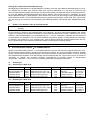
Der Einbau ist wie folgt vorzunehmen (siehe Bild 8 bzw. Bild 9):
Vorsicht
Vor dem Öffnen des Gerätes ist der Netzstecker zu ziehen und eventuell angeschlossene Batterieleitungen sind abzustecken !
- Zum Öffnen des Gerätes ist der Deckel an der Oberseite des Gehäuses zu entfernen.
- Der Nachrüstsatz NRS 90224 ist mit der Bauteile-Seite nach links (von der Frontseite aus gesehen) einzustecken
bis er einrastet.
- Der Gerätedeckel ist wieder zu befestigen.
13
NRS 90 224
S 406
S 405
B 411
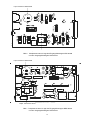
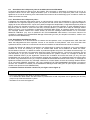
Bild 8
Printplatte 84187 in DPA 4120 mit Lage des NRS 90224 Pilotton & Erdschluß Überwachung,
der Steckbrücke B411 und S405, S406 zur Ausgangsspannungs-Umschaltung
14
NRS 90 224
S 406
S 405
B 411
Bild 9
Printplatte 84175 in DPA 4140 mit Lage des NRS 90224 Pilotton & Erdschluß Überwachung,
der Steckbrücke B411 und S405, S406 zur Ausgangsspannungs-Umschaltung
Prüfung der Funktion Pilotton-Überwachung:
Bei eingebautem NRS 90224 und eingeschaltetem Verstärker muss die grüne READY-Betriebsanzeige (7) leuchten. Zur Funktionskontrolle der Pilotton-Überwachung dient die Prüf- und Reset-Taste TEST (3). Bei gedrückter
Taste TEST wird der 19 kHz-Generator abgeschaltet, die grüne READY-Betriebsanzeige erlischt und das
READY-Störungsmelde-Relais schaltet in Ruhelage. Etwa 3s nach loslassen der Taste TEST muss die Betriebsanzeige wieder leuchten. Hiermit lassen sich auch Systeme mit Havarie-Umschaltung prüfen.
15
Prüfung der Funktion Erdschluß-Überwachung:
Bei eingebautem NRS 90224 und eingeschaltetem Verstärker muss die grüne READY-Betriebsanzeige (7) leuchten. Schaltet man mit Hilfe einer externen Taste einen 47kOhm Widerstand ca. 5 sek lang von einem Pol des
100V-Lautsprechernetzes gegen Schutzerde, muß die entsprechende rote GROUND FAULT Anzeige (6) aufleuchten und das READY-Störungsmelde-Relais des INPUT MODUL NRS 90225 schaltet in Ruhelage, die grüne
READY-Betriebsanzeige (7) bleibt erhalten. Nach loslassen der Taste muß die Anzeige und die Störungsmeldung
weiter bestehen bleiben. Um die Erdschluß-Überwachung wieder zurückzusetzen ist die Taste TEST (3) zu betätigen. Zur Prüfung der Funktionen bei Verwendung des REMOTE MODUL NRS 90222 siehe PROMATRIX Handbuch.
9.
Einbau in 19"-Gehäuse oder 19"-Gestellschränke
Hinweis
Ein Betrieb des Verstärkers DPA 4120 oder DPA 4140 mit entfernter Gehäuseabdeckung ist nicht
zulässig.
Für den Einbau in Gehäuse und Gestellschränke ist zu beachten, daß eine ausreichende Belüftung der Geräte
möglich ist. Zwischen der Verstärker Rückseite und der Gehäuse-Innenseite ist ein freier Luftkanal bis zur oberen
Gehäuse- oder Schrankentlüftung von mindestens 60 mm x 330 mm vorzusehen. Oberhalb des Schrankes soll
ein freier Raum von mindestens 100 mm für die Entlüftung vorgesehen werden. Da beim Betrieb die Temperatur
im Gehäuse- oder Schrank um 10°C ansteigen kann, muß die maximal zulässige Umgebungstemperatur der übrigen im Gestellschrank oder Gehäuse befindlichen Module und Baugruppen beachtet werden.
Hinweis
10.
Die max. Umgebungstemperatur von +40°C soll für störungsfreien Betrieb nicht überschritten weden.
Groundlift Schalter CIRCUIT A TO CHASSIS SWITCH
Mit dem Groundlift Schalter CIRCUIT A TO CHASSIS SWITCH (19) kann die Verbindung Signal-Masse zum Chassis (Schutzerde) getrennt werden. Hierdurch können Brumm-Probleme, die durch Erdschleifen entstehen, beseitigt
werden, ohne die Sicherheit zu beeinträchtigen. Sind mehrere Geräte mit Groundlift Schaltern in einem Gehäuse
oder Gestellschrank eingebaut, ist es zweckmäßig, alle Groundlift Schalter auf „ungrounded“ und nur ein Gerät auf
„grounded“ zu schalten. Die Impedanz zwischen Signal-Masse und Chassis beträgt im Schaltzustand
„ungrounded“ 100 kOhm // 100 nF und ist zur Einhaltung der EMV Störfestigkeit erforderlich.
11.
Sicherungen
11.1 Sicherungen in DPA 4120
Einbauplatz
Sicherungshalter (11)
Sicherungshalter (11)
Printplatte 86243
Printplatte 85270
Printplatte 85270
Pos.
F601
F601
F602
F502
F503
Verwendung
Netzsicherung für 230V~ AC
Netzsicherung für 115V~ AC
Netzsicherung für 100V - 250V
Batteriesicherung 24V DC
Batteriesicherung 24V DC
Wert
T2A
T4A
T1A
15A
15A
Abmessungen
5x20 mm
5x20 mm
8.5xRM 5.08mm
Flachsteck-Sicher.
Flachsteck-Sicher.
Norm
IEC 127-2-3
IEC 127-2-3
IEC 127-3/4
DIN 72581-3
DIN 72581-3
Wert
T4A
T8A
T1A
25A
25A
Abmessungen
5x20 mm
5x20 mm
8.5xRM 5.08mm
Flachsteck-Sicher.
Flachsteck-Sicher.
Norm
IEC 127-2-3
IEC 127-2-3
IEC 127-3/4
DIN 72581-3
DIN 72581-3
11.2 Sicherungen in DPA 4140
Einbauplatz
Sicherungshalter (11)
Sicherungshalter (11)
Printplatte 86243
Printplatte 85268
Printplatte 85268
Pos.
F601
F601
F602
F502
F503
Verwendung
Netzsicherung für 230V~ AC
Netzsicherung für 115V~ AC
Netzsicherung für 100V - 250V
Batteriesicherung 24V DC
Batteriesicherung 24V DC
16
F 503 F 502
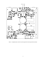
Bild 10 Printplatte 85270 in DPA 4120 mit Lage der DC Sicherungen F502 und F503
17
F 503 F 502
Bild 11 Printplatte 85268 in DPA 4140 mit Lage der DC Sicherungen F502 und F503
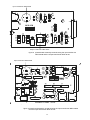
18
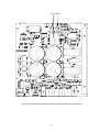
F 601
F 602
Bild 12 Printplatte 86243 DPA 4120 und DPA 4140 mit Lage der AC Sicherungen F601 und F602
Vorsicht
Vor dem Öffnen des Gerätes ist der Netzstecker zu ziehen und eventuell angeschlossene Batterieleitungen sind abzustecken !
Auswechseln der Sicherungen F502 und F503 (Nur vom Fachmann auszuführen!)
Die Batteriesicherungen F502 und F503 befinden sich auf der Netzteil-Printplatte 85270 (DPA 4120) bzw. 85268
(DPA 4140) hinter den AMP-Batterie-Anschlüssen (siehe Bild 10 bzw. Bild 11). Zum Auswecheln dieser Sicherungen ist der Gerätedeckel zu entfernen und die an der Geräterückwand befestigte Netzeingang-Printplatte 86243
auszubauen. Dazu ist die gelb/grüne Anschlußleitung vom Schutzleiteranschluß an der Geräterückwand abzustecken. Wenn beim AMP-Stecker die Verriegelungslasche zusammengedrückt wird, kann dieser ohne großen Kraftaufwand abgesteckt werden. Nun sind die mit A gekennzeichneten drei Schrauben zu entfernen (siehe Bild der
Geräterückwand auf Seite 2). Jetzt kann die Netzeingang-Printplatte 86243 hochgeklappt werden. Hierbei ist darauf zu achten, daß keine Leitungen oder Bauteile beschädigt werden. Die Sicherungen F502 und F503 sind nun
zugänglich und können nach oben herausgezogen werden. Der Einbau der Netzeingang-Printplatte 86243 ist in
umgekehrter Reihenfolge vorzunehmen. Die gelb/grüne Anschlußleitung ist wieder am Schutzleiteranschluß an der
Geräterückwand anzustecken und durch Zug an der Leitung auf festen Sitz zu prüfen. Der Gerätedeckel ist wieder
zu befestigen.
Achtung
Aus Sicherheitsgründen ist darauf zu achten, daß Leitungen, die sich unterhalb der NetzeingangPrintplatte befinden nach dem Zusammenbau einen Abstand zu dieser von mindestens 6mm haben.
19
12.
Technische Daten
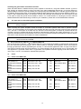
12.1
DPA 4120 Leistungsverstärker 200 W
Stromversorgung:
Netzbetrieb
Netzfrequenz
Schutzklasse
115 V / 230 V~ AC, r10 %
50 - 60 Hz
,
Netzbetrieb
Leerlauf
Normalbetrieb (-10 dB)
Alarm (-3 dB)
Nennbedingungen
Netz-Einschaltstoßstrom
Netzbetrieb
Leerlauf
Normalbetrieb (-10 dB)
Alarm (-3 dB)
Nennbedingungen
Netz-Einschaltstoßstrom
Unetz / V
Inetz / A
Pnetz / VA
Pnetz / W
Pout / W
Pv / W
230
230
230
230
0.13
0.83
1.67
2.27
< 29 A
30
191
384
522
16
138
298
415
0
20
100
200
16
118
198
215
Unetz / V
Inetz / A
Pnetz / VA
Pnetz / W
Pout / W
Pv / W
115
115
115
115
0.26
1.67
3.34
4.54
< 20 A
30
191
384
522
16
138
298
415
0
20
100
200
16
118
198
215
Pnetz / VA = Scheinleistung Unetz*Inetz; Pnetz / W = Wirkleistung; Pout / W = Ausgangsleistung; Pv / W =Verlustleistung
Batteriebetrieb
24 V DC, -10/+30 %
Batteriebetrieb
UB / V
IB / A
Pi / W
Pout / W
Pv / W
24
24
24
24
2.5m
0.43
3.74
9.10
< 3.8 A
60m
10
90
218
0
0
20
131
60m
10
90
87
Standby
Leerlauf
Normalbetrieb (-10 dB)
Nennbedingungen
Batterie-Einschaltstoßstrom
Pi / W = Eingangsleistung UB*IB; Pout / W = Ausgangsleistung; Pv / W = Verlustleistung
B
Eigenschaften des Eingangs:
Nenneingangspegel
Nenneingangsimpedanz
elektronisch symmetrisch
775 mV = 0 dBu
t 10 kOhm
Eigenschaften des Leistungs-Ausgangs:
Nennausgangsleistung bei Netzbetrieb
Nennlastimpedanz
Übertragungsbereich
Klirrfaktor bei 1kHz und Nennleistung
Störspannung (A)
symmetrisch, erdfrei
200 W (nach IEC 268-3)
50 Ohm / 100V; 25 Ohm / 70 V; 12.5 Ohm / 50 V
oder 4 Ohm / 28 V
60 Hz .. 20 kHz
d 1%
d 1.2mV = -56 dBu
Eigenschaften des Monitor-Ausgangs:
Nennausgangsspannung
Nennlastimpedanz
elektronisch symmetrisch
2 V = + 8.2 dBu
600 Ohm
Umgebungstemperatur
Abmessungen (B x H x T)
Einbautiefe ohne / mit Steckverbindungen
Gewicht ohne NRS
Farbe
+5 °C .. +40 °C
483 x 132 x 345 mm
340 mm / max. 400 mm
13.2 kg
anthrazit
20
12.2 DPA 4140 Leistungsverstärker 400 W
Stromversorgung:
Netzbetrieb
Netzfrequenz
Schutzklasse
115 V / 230 V~ AC, r10 %
50 - 60 Hz
,
Netzbetrieb
Leerlauf
Normalbetrieb (-10 dB)
Alarm (-3 dB)
Nennbedingungen
Netz-Einschaltstoßstrom
Netzbetrieb
Leerlauf
Normalbetrieb (-10 dB)
Alarm (-3 dB)
Nennbedingungen
Netz-Einschaltstoßstrom
Unetz / V
Inetz / A
Pnetz / VA
Pnetz / W
Pout / W
Pv / W
230
230
230
230
0.19
1.60
3.10
4.43
< 36 A
44
368
713
1019
23
263
562
811
0
40
200
400
23
223
362
411
Unetz / V
Inetz / A
Pnetz / VA
Pnetz / W
Pout / W
Pv / W
115
115
115
115
0.38
3.19
6.20
8.86
< 21 A
44
368
713
1019
23
263
562
811
0
40
200
400
23
223
362
411
Pnetz / VA = Scheinleistung Unetz*Inetz; Pnetz / W = Wirkleistung; Pout / W = Ausgangsleistung; Pv / W =Verlustleistung
Batteriebetrieb
24 V DC, -10/+30 %
Batteriebetrieb
UB / V
Standby
Leerlauf
Normalbetrieb (-10 dB)
Nennbedingungen
Batterie-Einschaltstoßstrom
24
24
24
24
IB / A
2.5m
0.62
7.1
17.3
< 3.8 A
Pi / W
Pout / W
60m
15
170
415
0
0
40
249
Pv / W
60m
15
130
166
Pi / W = Eingangsleistung UB*IB; Pout / W = Ausgangsleistung; Pv / W = Verlustleistung
B
Eigenschaften des Eingangs:
Nenneingangspegel
Nenneingangsimpedanz
elektronisch symmetrisch
775 mV = 0 dBu
t 10 kOhm
Eigenschaften des Leistungs-Ausgangs:
Nennausgangsleistung bei Netzbetrieb
Nennlastimpedanz
Übertragungsbereich
Klirrfaktor bei 1kHz und Nennleistung
Störspannung (A)
symmetrisch, erdfrei
400 W (nach IEC 268-3)
25 Ohm / 100V; 12.5 Ohm / 70 V; 6.25 Ohm / 50 V
oder 4 Ohm / 40 V
60 Hz .. 20 kHz
d 1%
d 1.2mV = -56 dBu
Eigenschaften des Monitor-Ausgangs:
Nennausgangsspannung
Nennlastimpedanz
elektronisch symmetrisch
2 V = + 8.2 dBu
600 Ohm
Umgebungstemperatur
Abmessungen (B x H x T)
Einbautiefe ohne / mit Steckverbindungen
Gewicht ohne NRS
Farbe
+5 °C .. +40 °C
483 x 132 x 345 mm
340 mm / max. 400 mm
16.7 kg
anthrazit
Nachrüstsätze für DPA 4120 und DPA 4140:
NRS 90208 Eingangs-Übertrager für erdfrei, symmetrischen Eingang
NRS 90222 Remote Modul
NRS 90224 Pilotton & Erdschluß Überwachung
NRS 90225 Standard Eingangsmodul
NRS 90227 Ausgangs-Übertrager für erdfrei, symmetrischen Monitor-Ausgang
21
Art. Nr.
Art. Nr.
Art. Nr.
Art. Nr.
Art. Nr.
121 641
121 674
121 676
121 677
121 679
13.
Technische Daten der Nachrüstsätze für den Verstärker DPA 4120 / DPA 4140
13.1
NRS 90225 Standard Eingangsmodul
siehe technische Daten DPA 4120 / DPA 4140
13.2
NRS 90222 Remote Modul
siehe technische Daten DPA 4120 / DPA 4140
13.3
NRS 90208 Eingangs-Übertrager für erdfrei, symmetrischen Eingang
Übertragungsbereich
Eingangsimpedanz
Leerlauf-Übersetzungsverhältnis
Wicklungswiderstand primär
Wicklungswiderstand sekundär
13.4
20 Hz .. 20 kHz
t 10 kOhm
1:1
1420 Ohm bei 20°C
1420 Ohm bei 20°C
NRS 90227 Ausgangs-Übertrager für erdfrei, symmetrischen Monitor-Ausgang
Übertragungsbereich
Nennlast-Impedanz
Leerlauf-Übersetzungsverhältnis
Wicklungswiderstand primär
Wicklungswiderstand sekundär
13.5
40 Hz .. 20 kHz
t 600 Ohm
1:1
18 Ohm bei 20°C
18 Ohm bei 20°C
NRS 90224 Pilotton & Erdschluß Überwachung
13.5.1 Pilotton Überwachung
Pilotton-Frequenz
Ansprechschwelle für Fehlererkennung
Störmelde-Ausgang mit NRS 90225
Störmelde-Ausgang mit NRS 90222
19 kHz r 1%
d 12 mV
Sammelstörmeldung mit READY-Relais
PROMATRIX Manager DPM 4000
13.5.2 Erdschluß Überwachung
Eingang
Störmelde-Ausgang mit NRS 90225
Störmelde-Ausgang mit NRS 90222
Spannungsfestigkeit
Ansprechschwelle für Fehlererkennung
Lautsprecher-Linie 4 Ohm / 50V / 70V / 100V
Sammelstörmeldung mit READY-Relais
PROMATRIX Manager DPM 4000
1000Veff
d 50kOhm
22
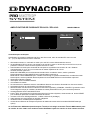
POWER AMPLIFIER DPA 4120 / DPA 4140
OWNER'S MANUAL
DPA 4140
4 0 0 WATT S P OW E R A M PL I FI E R
CLIP
TEST
0dB
-13dB
READY
STANDBY
GROUND
FAULT
PROTECT
Performance Features
Power amplifier with 200 W or 400 W output power according to the IEC 283-3 standard within a
19“ - cabinet (3 HU) providing the following functions:
x supported are 115/230V AC mains as well as 24V DC emergency power source
x power amplifiers DPA 4120 providing 200 W or DPA 4140 providing 400 W output power, idling and short-circuit
protection
x output transformer for balanced, floating 100 V speaker networks of optionally 70 V, 50 V or
4 ohms for low-impedance operation
x optional input modules:
standard operation INPUT MODULE with level control, electronically balanced input and MONITOR output with
optional transformer or
REMOTE MODULE for controlling and monitoring the PROMATRIX system, electronic level controls,
electronically balanced input and MONITOR output with optional transformer
x integrated stand-by power supply
x mains POWER ON/OFF switch
x ground lift switch
x remotely controllable mains and battery operation with initial current inrush limiter
x power-on switching noise suppression
x status-LED indicators for operation (READY), STANDBY, thermal overload (PROTECT) and
occurrence of GROUND FAULT conditions at the power output
x fault message according to the IEC 849 standard
x TEST button to switch between system and average operation, respectively a RESET button to restart after the
occurrence of ground fault conditions
x LED level meter instrument with a display range of -13 dB to 0 dB and CLIP
x integrated relays for single call and obligatory reception
x active, temperature controlled ventilation
x pilot tone and ground fault surveillance module according to the DIN/VDE 0800 standard (optional)
The extension-kit NRS 90208 (input transformer) has been integrated in the input module NRS 90222
starting with the serial number 10461 and in the input module NRS 90225 starting with the serial number
12339 and higher.
23
,03257$176$)(7<,16758&7,216
7KH OLJKWQLQJ ÀDVK ZLWK DUURZKHDG V\PERO ZLWKLQ DQ
HTXLODWHUDO WULDQJOH LV LQWHQGHG WR DOHUW WKH XVHU WR WKH
SUHVHQFHRIXQLQVXODWHGÄGDQJHURXVYROWDJH³ZLWKLQWKH
SURGXFW¶VHQFORVXUHWKDWPD\EHRIVXI¿FLHQWPDJQLWXGH
WRFRQVWLWXWHDULVNRIHOHFWULFVKRFNWRSHUVRQV
7KHH[FODPDWLRQSRLQWZLWKLQDQHTXLODWHUDOWULDQJOHLV
LQWHQGHGWRDOHUWWKHXVHUWRWKHSUHVHQFHRILPSRUWDQW
RSHUDWLQJDQGPDLQWDQFHVHUYLFLQJLQVWUXFWLRQVLQWKH
OLWHUDWXUHDFFRPSDQ\LQJWKHDSSOLDQFH
5HDGWKHVHLQVWUXFWLRQV
.HHSWKHVHLQVWUXFWLRQV
+HHGDOOZDUQLQJV
)ROORZDOOLQVWUXFWLRQV
'RQRWXVHWKLVDSSDUDWXVQHDUZDWHU
&OHDQRQO\ZLWKDGU\FORWK
'RQRWEORFNDQ\YHQWLODWLRQRSHQLQJV,QVWDOOLQDFFRUGDQFHZLWKWKHPDQXIDFWXUHVLQVWUXFWLRQV
'RQRWLQVWDOOQHDUDQ\KHDWVRXUFHVVXFKDVUDGLDWRUVKHDWUHJLVWHUVVWRYHVRURWKHUDSSDUDWXV
LQFOXGLQJDPSOL¿HUVWKDWSURGXFHKHDW
'RQRWGHIHDWWKHVDIHW\SXUSRVHRIWKHSRODUL]HGRUJURXQGLQJW\SHSOXJ$SRODUL]HGSOXJKDVWZREODGHV ZLWKRQHZLGHUWKDQWKHRWKHU$JURXQGLQJW\SHSOXJKDVWZREODGHVDQGDWKLUGJURXQGLQJSURQJ7KHZLGH EODGHRUWKHWKLUGSURQJDUHSURYLGHGIRU\RXUVDIHW\,IWKHSURYLGHGSOXJGRHVQRW¿WLQWR\RXURXWOHWFRQVXOWDQ
HOHFWULFDQIRUUHSODFHPHQWRIWKHREVROHWHRXWOHW
3URWHFWWKHSRZHUFRUGIURPEHLQJZDONHGRQRUSLQFKHGSDUWLFXODUO\DWSOXJVFRQYHQLHQFHUHFHSWDFOHV
DQGWKHSRLQWZKHUHWKH\H[LWIURPWKHDSSDUDWXV
2QO\XVHDWWDFKPHQWVDFFHVVRULHVVSHFL¿HGE\WKHPDQXIDFWXUHU
8QSOXJWKLVDSSDUDWXVGXULQJOLJKWQLQJVWRUPVRUZKHQXQXVHGIRUORQJSHULRGVRIWLPH
5HIHUDOOVHUYLFLQJWRTXDOL¿HGVHUYLFHSHUVRQQHO6HUYLFLQJLVUHTXLUHGZKHQWKHDSSDUDWXVKDVEHHQGDPDJHG
LQDQ\ZD\VXFKDVSRZHUVXSSO\FRUGRUSOXJLVGDPDJHGOLTXLGKDVEHHQVSLOOHGRUREMHFWVKDYHIDOOHQLQWRWKH
DSSDUDWXVWKHDSSDUDWXVKDVEHHQH[SRVHGWRUDLQRUPRLVWXUHGRHVQRWRSHUDWHQRUPDOO\RUKDVEHHQGURSSHG
'RQRWH[SRVHWKLVHTXLSPHQWWRGULSSLQJRUVSODVKLQJDQGHQVXUHWKDWQRREMHFWV¿OOHGZLWKOLTXLGVVXFKDVYDVHV
DUHSODFHGRQWKHHTXLSPHQW
7RFRPSOHWHO\GLVFRQQHFWWKLVHTXLSPHQWIURPWKH$&0DLQVGLVFRQQHFWWKHSRZHUVXSSO\FRUGSOXJIURPWKH$&
UHFHSWDFOH
7KHPDLQVSOXJRIWKHSRZHUVXSSO\FRUGVKDOOUHPDLQUHDGLO\RSHUDEOH
0DQDJHPHQWRI:(((ZDVWHHOHFWULFDODQGHOHFWURQLFHTXLSPHQWDSSOLFDEOHLQ0HPEHU6WDWHVRIWKH
(XURSHDQ8QLRQDQGRWKHU(XURSHDQFRXQWULHVZLWKLQGLYLGXDOQDWLRQDOSROLFLHVRQWKHPDQDJHPHQWRI:(((
7KHV\PERORQWKHSURGXFWRURQLWVSDFNDJLQJLQGLFDWHVWKDWWKLVSURGXFWPD\QRWEHWUHDWHGDVUHJXODU
KRXVHKROGZDVWHEXWKDVWREHGLVSRVHGWKURXJKUHWXUQLQJLWDWD7HOH[GHDOHU
,03257$176(59,&(,16758&7,216
&$87,21
7KHVHVHUYLFLQJLQVWUXFWLRQVDUHIRUXVHE\TXDOL¿HGSHUVRQQHORQO\7RUHGXFHWKHULVNRI HOHFWULFVKRFNGRQRWSHUIRUPDQ\VHUYLFLQJRWKHUWKDQWKDWRQWDLQHGLQWKH2SHUDWLQJ
,QVWUXFWLRQVXQOHVV\RXDUHTXDOL¿HGWRGRVR5HIHUDOOVHUYLFLQJWRTXDOL¿HGVHUYLFHSHUVRQQHO
6HFXULW\UHJXODWLRQVDVVWDWHGLQWKH(19'(,(&DQGWKH&6$(KDYHWREHREH\HGZKHQ
VHUYLFLQJWKHDSSOLDQFH
8VHRIDPDLQVVHSDUDWRUWUDQVIRUPHULVPDQGDWRU\GXULQJPDLQWHQDQFHZKLOHWKHDSSOLDQFHLVRSHQHGQHHGVWREH
RSHUDWHGDQGLVFRQQHFWHGWRWKHPDLQV
6ZLWFKRIIWKHSRZHUEHIRUHUHWUR¿WWLQJDQ\H[WHQVLRQVFKDQJLQJWKHPDLQVYROWDJHRUWKHRXWSXWYROWDJH
7KHPLQLPXPGLVWDQFHEHWZHHQSDUWVFDUU\LQJPDLQVYROWDJHDQGDQ\DFFHVVLEOHPHWDOSLHFHPHWDOHQFORVXUH
UHVSHFWLYHO\EHWZHHQWKHPDLQVSROHVKDVWREHPPDQGQHHGVWREHPLQGHGDWDOOWLPHV7KHPLQLPXPGLVWDQFH
EHWZHHQSDUWVFDUU\LQJPDLQVYROWDJHDQGDQ\VZLWFKHVRUEUHDNHUVWKDWDUHQRWFRQQHFWHGWRWKHPDLQVVHFRQGDU\
SDUWVKDVWREHPPDQGQHHGVWREHPLQGHGDWDOOWLPHV
5HSODFLQJVSHFLDOFRPSRQHQWVWKDWDUHPDUNHGLQWKHFLUFXLWGLDJUDPXVLQJWKHVHFXULW\V\PERO1RWHLVRQO\
SHUPLVVLEOHZKHQXVLQJRULJLQDOSDUWV
$OWHULQJWKHFLUFXLWU\ZLWKRXWSULRUFRQVHQWRUDGYLFHLVQRWOHJLWLPDWH
$Q\ZRUNVHFXULW\UHJXODWLRQVWKDWDUHDSSOLFDEOHDWWKHORFDWLRQZKHUHWKHDSSOLDQFHLVEHLQJVHUYLFHGKDYHWREH
VWULFWO\REH\HG7KLVDSSOLHVDOVRWRDQ\UHJXODWLRQVDERXWWKHZRUNSODFHLWVHOI
$OOLQVWUXFWLRQVFRQFHUQLQJWKHKDQGOLQJRI026FLUFXLWVKDYHWREHREVHUYHG
127(
6$)(7<&20321(170867%(5(3/$&('%<25,*,1$/3$57
24
Indicators, controls and connections
1 2
DPA 4140
400 WATT S PO WER A MPLI FI ER
TEST
3
READY
STANDBY
GROUND
FAULT
4
PROTECT
CLIP
0 dB
-13 dB
5
7 6
8
A
9
10
A
11
T4A FOR 230V
T8A FOR 115V
POWER
12
NO USER SERVICEABLE PARTS INSIDE. REFER SERVICING
TO QUALIFIED SERVICE PERSONNEL.
VOLTAGE
SELECTOR
115V
230V
B
13
A
DPA 4140
121629
AC MAINS INPUT
115V /230V AC 50-60 Hz
INPUT
14
THRU
15
MADE IN GERMANY
CAUTION: FOR CONTINUED PROTECTION AGAINST RISK OF FIRE
REPLACE WITH SAME TYPE AND VALUE FUSE INDICATED.
ATTENTION: REMPLACER PAR UN FUSIBLE DE MEME TYPE
COMME INDIQUE.
B
CAUTION
A
ADDRESS
RISK OF ELECTRIC SHOCK
DO NOT OPEN
3
2
1
OUTPUT
VOLTAGE
WARNING: TO REDUCE THE RISK OF FIRE OR ELECTRIC SHOCK,
CIRCUIT TO
CHASSIS SWITCH
A
9
VOR ÖFFNEN DES GERÄTES NETZSTECKER ZIEHEN
19
10
A
T4A FOR 230V
T8A FOR 115V
16
1 2 3 4 5
18
11
POWER
7
8
9
POWER OUTPUT
GROUNDED
UNGROUNDED
20
10
REMOTE
CONTROL
AVIS: RISQUE DE CHOC ELECTRIQUE. NE PAS OUVRIR.
+
0
LEVEL
DO NOT EXPOSE THIS APPLIANCE TO RAIN OR MOISTURE.
DC INPUT 24V
4 5 6
12
VOLTAGE
SELECTOR
115V
230V
90225
17
B
15
A
NO USER SERVICEABLE PARTS INSIDE. REFER SERVICING
TO QUALIFIED SERVICE PERSONNEL.
DPA 4140
B
INPUT
14
121629
AC MAINS INPUT
115V /230V AC 50-60 Hz
ADDRESS
MADE IN GERMANY
A
CAUTION: FOR CONTINUED PROTECTION AGAINST RISK OF FIRE
REPLACE WITH SAME TYPE AND VALUE FUSE INDICATED.
ATTENTION: REMPLACER PAR UN FUSIBLE DE MEME TYPE
B
COMME INDIQUE.
B
CAUTION
ADDRESS
RISK OF ELECTRIC SHOCK
DO NOT OPEN
OUTPUT
VOLTAGE
WARNING: TO REDUCE THE RISK OF FIRE OR ELECTRIC SHOCK,
DO NOT EXPOSE THIS APPLIANCE TO RAIN OR MOISTURE.
21
A
THRU
IN
22
REMOTE
CONTROL
AVIS: RISQUE DE CHOC ELECTRIQUE. NE PAS OUVRIR.
DC INPUT 24V
+
GROUNDED
UNGROUNDED
20
1
2
3
4
5
6
7
8
9
10
11
12
13
14
15
CIRCUIT TO
CHASSIS SWITCH
POWER OUTPUT
OUT
23
STATUS
VOR ÖFFNEN DES GERÄTES NETZSTECKER ZIEHEN
19
18
1 2 3 4 5
17
level meter instrument
CLIP indicator
Test and Reset button TEST
STANDBY indicator
Fault indicator PROTECT
Fault indicator GROUND FAULT
Mode indicator READY
Ventilation louvres
Mains power switch POWER
Mains power connector AC MAINS INPUT
Mains fuse FUSE
Mains VOLTAGE SELECTOR
Input LEVEL control
INPUT socket
THRU socket
16
17
18
19
20
21
22
23
A
B
25
90222
B
REMOTE CONTROL connector
POWER OUTPUT
Ventilation louvres
CIRCUIT A TO CHASSIS SWITCH
DC INPUT 24V = (battery)
IDENT ADDRESS switch
REMOTE CONTROL connectors
STATUS indicator
locking screws power supply printed board
locking screws INPUT MODULE
Contents
Performance Features ................................................................................................................................. 23
Indicators, controls and connections ........................................................................................................... 25
1.
Utilization ..................................................................................................................................................... 27
2.
Installation ................................................................................................................................................... 27
3.
Before the first operation.............................................................................................................................. 27
3.1 Mains operation ................................................................................................................................... 27
3.2 Battery operation 24V DC ..................................................................................................................... 28
4.
INPUT .......................................................................................................................................................... 28
5.
Outputs......................................................................................................................................................... 29
5.1 POWER OUTPUT................................................................................................................................. 29
5.2 POWER OUTPUT for 100V (70V or 50V) loudspeaker systems ......................................................... 29
5.3 SINGLE CALL and obligatory reception relays OVERRIDE BYPASS ................................................. 29
5.4 POWER OUTPUT for low impedance loudspeaker systems ............................................................... 29
5.5 MONITOR output .................................................................................................................................. 30
5.6 REMOTE CONTROL connector (only NRS 90225) ............................................................................. 30
6.
Indicators ..................................................................................................................................................... 30
6.1 STANDBY indicator .............................................................................................................................. 30
6.2 READY indicator ................................................................................................................................... 30
6.3 PROTECT indicator .............................................................................................................................. 30
6.4 GROUND FAULT indicator................................................................................................................... 30
6.5 Aussteuerungskontrolle und CLIP-Anzeige.......................................................................................... 31
7.
Switching the output voltage ........................................................................................................................ 31
8.
Enhanced application field ........................................................................................................................... 32
8.1 General input module NRS 90225........................................................................................................ 32
8.2 Remote module NRS 90222................................................................................................................. 32
8.3 NRS 90208 input transformer for the floating, balanced input ............................................................. 33
8.4 NRS 90227 output transformer for the floating, balanced monitor output............................................ 33
8.5 NRS 90224 pilot tone and ground fault surveillance ............................................................................ 35
8.5.1 Pilot tone surveillance ................................................................................................................. 35
8.5.2 Ground fault surveillance ............................................................................................................ 35
9.
19"-case and 19“-rack shelf system installation .......................................................................................... 38
10.
Ground lift switch CIRCUIT ATO CHASSIS SWITCH ................................................................................. 38
11.
Fuses ........................................................................................................................................................... 38
11.1 Fuses in the DPA ................................................................................................................................ 38
11.2 Fuses in the DPA ................................................................................................................................ 38
12.
Power amplifier specifications ..................................................................................................................... 42
12.1 DPA 4120 power amplifier 200 W....................................................................................................... 42
12.2 DPA 4140 power amplifier 400 W....................................................................................................... 43
13.
Extension specifications............................................................................................................................... 44
13.1 NRS 90225 general input module....................................................................................................... 44
13.2 NRS 90222 remote module ................................................................................................................ 44
13.3 NRS 90208 input transformer for floating, balanced input ................................................................. 44
13.4 NRS 90227 output transformer for floating, balanced monitor output................................................ 44
13.5 NRS 90224 pilot tone and ground fault surveillance .......................................................................... 44
14.
Block diagrams ............................................................................................................................................ 67
14.1 Power amplifiers DPA 4120 / DPA 4140 ............................................................................................. 67
14.2 NRS 90225 general input module....................................................................................................... 68
14.3 NRS 90222 remote module ................................................................................................................ 69
14.4 NRS 90224 pilot tone and ground fault surveillance .......................................................................... 70
Warranty....................................................................................................................................................... 72
15.
26
1.
Utilization
The amplifiers DPA 4120 and DPA 4140 are specially designed for the power-consistent and reliable operation of
PA-systems. The DPA 4120 and DPA 4140 are intended to be used in company intercom, alarm and background
music transmission installations, offices and commercial areas, congregation and sport centers, schools, churches,
hotels, hospitals, shopping malls and super markets, cruise ships, and other similar applications.
2.
Installation
When installing the amplifiers, it is important to assure that for ventilation reasons the front-to-rear air circulation is
guaranteed (for details on 19"-case or 19“-rack shelf installation please refer to paragraph 9).
To maintain EMC it is necessary that all input, output, and control lines – except for the power cords – are shielded.
Within metal housings or closed rack shelf systems, unshielded output and control cabling is allowable. Shielding is
accomplished by connecting the individual cable screens to the enclosure or rack shelf ground potential.
The amplifier has to be protected from:
- water drops or splashes
- direct sunlight
- high ambient temperatures and the direct radiation of heat sources
- high humidity and moisture
- heavy dust
- massive vibrations
Moving the amplifier from a cold into a warm environment can result in the occurrence of condensation on inner
parts. Operating the appliance is only permissible after it has accommodated to the altered temperature
(approximately after one hour).
Should it happen that foreign solid parts or liquids inadvertently intrude the enclosure, unplug the device from the
power source and have it checked by a DYNACORD service center, before using it again.
Cleaning the appliance should not be performed using chemical solvents or sprays, as this might damage the finish
and moreover could cause hazard fire.
3.
Before the first operation
These power amplifiers are designed to be operated with different input modules. The general input module NRS
90225 is meant for all conventional applications. It allows to remotely start the amplifiers via control lines, monitor
their operation by use of the incorporated fault relay, and monitor the transmitted audio signals through the monitor
output. Using the remote control module NRS 90222, the amplifiers are connected to the PROMATRIX manager
DPM 4000 via RS-485 remote interface providing complete remote operation and surveillance. The desired input
module has to be inserted into the module shaft on the rear of the power amplifier. It has to be tightened using the
two locking screws (B) (refer also to the paragraphs 8.1 and 8.2).
3.1 Mains operation
For normal AC mains operation, the included mains cord has to be connected to a 230V or 115V 50/60Hz wall
outlet. On the appliance itself, the cord has to be connected to the 3-pole mains socket (10).
Caution
The appliance is factory preset to 230V AC. Switching to 115V AC is accomplished using the voltage
selector (12).
DPA 4120: For 115V AC operation, the mains fuse (11) has to be replaced by a slow blowing
4 ampere type, labeled "T4A" (see also paragraph 11.1).
DPA 4140: For 115V AC operation, the mains fuse (11) has to be replaced by a slow blowing
8 ampere type, labeled "T8A" (see also paragraph 11.2).
27
If the appliance is correctly connected and mains is present the green STANDBY indicator (4) will light. To remotely
start the amplifier when it is being operated on the mains, it is necessary to interconnect the contacts 3 - POWER
REMOTE and 2 - GROUND STANDBY on the pin terminal strip REMOTE CONTROL (16) (see also paragraph
5.6).
The main power switch POWER (9) on the rear of the appliance is meant for service and maintenance purposes.
This allows bridging the mains switching relay, which provides the possibility to operate the amplifier without
remote start.
Note
The main power switch POWER (9) on the appliance's rear is only meant for maintenance.
Remotely switching off the device is not possible when the POWER switch is engaged.
Both amplifiers, the DPA 4120 and the DPA 4140, employ power-on switching delays of approximately 3 sec. After
this time, the green READY indicator lights and the READY fault message relay picks up when no error is being
detected (see also paragraph 6.2).
3.2 Battery operation 24V DC
The amplifiers, DPA 4120 and DPA 4140, use the mains or alternatively an external 24V battery as power source.
Switching to battery is performed via integrated relays.
The battery has to be connected on the rear of the amplifiers (20) using insulated 6.3x0.8 mm AMP flat plug
connectors. The amplifiers are protected against polarity-mismatch. Each, the positive and negative conductors are
internally protected by fuses, located on the printed board assembly 85270 (DPA 4120) respectively 85268 (DPA
4140) (see also paragraph 11, figure 10 and 11).
The cable used for battery connection has to be at least 1.5 mm2 in diameter (DPA 4120) respectively 2.5 mm2
(DPA 4140). Using these diameters, the cable length for the one way distance should not exceed 4.0 m (max.
voltage drop <1V).
Caution
The DPA 4120 and DPA 4140 are to be operated only using ungrounded batteries or batteries with
grounded negative pole. Operation with grounded positive pole is not permissible.
4.
INPUT
The electronically balanced INPUT (14) providing a sensitivity of 775mV = 0dBu is meant for the connection of
control amplifiers. In case it is intended to supply several power amplifiers with identical input signals, these signals
can be taken from the THRU connector (15) (see also figure 1 and 2).
The input is prepared to be retrofitted with a input transformer. In case a floating input is needed, it is necessary to
install the optional extension NRS 90208 (see also paragraph 8.3).
On the general input module NRS 90225 the input level is set with the level control (13). For the remote control
module NRS 90222 the input level is determined by the setting of the internal electronic level control of the
PROMATRIX manager DPM 4000 (please also refer to the PROMATRIX handbook).
figure 1 connections of the input sockets
28
figure 2 LF cable for coupling two amplifiers DPA 41xx
5.
Outputs
5.1 POWER OUTPUT
The power output is balanced and off-ground potential. The output is factory-configured for the connection of 100V
loudspeaker systems. Connection has to be performed by inserting the supplied 5-pole plug into the power output
socket (17). Switching the output voltage to 70V, 50V or to low impedance operation (4 ohms) is possible using the
plug-in bridge B411 on the printed board assembly 84187 (DPA 4120) respectively 84175 (DPA 4140) (see also
paragraph 7).
figure 3 connection of the power output
5.2 POWER OUTPUT for 100V (70V or 50V) loudspeaker systems
If the distance between the amplifier and the loudspeakers exceeds 50 m, it is recommended to operate the
speaker systems using 100V matching transformers, to reduce line attenuation. This additionally offers a simple
way of distributing the output power capacity. In this way it is possible to connect a maximum of as many
loudspeaker systems as it takes until the total power consumption of the entire speaker network equals the power
output capacity of 200W (connection impedance 50 ohms) with the DPA 4120, respectively 400W (connection
impedance 25 ohms) with the DPA 4140. Connection is performed using the 100V output (17) (see also figure 3).
In a few special cases it is also possible to operate the loudspeaker systems with 70V or 50V output voltage (see
also paragraph 7).
Caution
It is possible that during operation shock-hazard output voltages can be present at the POWER
OUTPUT connector (>34V peak value). Thus, the connected loudspeaker groups have to be
installed in accordance to applicable security standards and regulations (see also paragraph 8.5.2).
5.3 SINGLE CALL and obligatory reception relays OVERRIDE BYPASS
Combined with the PROMATRIX manager DPM 4000 or other external controls it is also possible to transmit single
or collective calls with obligatory reception; i. e. bridging of possibly existing volume controls of the loudspeaker
systems. For details on how to connect the outputs, please refer to figure 3; for the connection of relays, please
refer to paragraph 5.6 respectively the PROMATRIX handbook.
5.4 POWER OUTPUT for low impedance loudspeaker systems
Switching the output to 4 ohms allows the connection of low impedance loudspeaker systems (4-16 ohms) (see
also paragraph 7 and figure 3). Because of the occurring line attenuation, the distance between amplifier and
loudspeaker system should not exceed 50m. Please make sure that the overall loudspeaker impedance does not
decline a value of 4 ohms and that the stated power handling capacity of a single speaker system is not exceeded.
29
5.5 MONITOR output
The MONITOR output (16) on the NRS 90225 allows the connection of an additional power amplifier for monitoring
purposes. The low impedance output is electronically balanced, which offers the possibility to achieve cable
lengths of up to 200 m. Connection is performed via the REMOTE CONTROL pin-connector strip (see also figure
4). For the remote control module NRS 90222, the MONITOR output is located on the REMOTE CONTROL
connector (22). The PROMATRIX manager DPM 4000 switches the signal to the according the monitor channel. In
case a floating output is required, the monitor output is prepared for retrofitting an output transformer; provided
through the optional extension NRS 90227 (please also refer to paragraph 8.4).
Note:
Functioning changes in the models DPA 4120 (starting with serial numbers: 100 11) and DPA 4140
(starting with serial numbers: 100 11) in association with the input module NRS 90225: To achieve reliable
attenuation of switching noise (knacks), the monitor output stays muted as long as the READY-relay is not
pulled. Because of circuit design reasons this causes that the monitor output is also muted even when a
ground-fault appears at the main output.
5.6 REMOTE CONTROL connector (only NRS 90225)
The 15-pole sub-D REMOTE CONTROL pin-connector strip (16) provides several different control in-/outputs:
- Ground of the stand-by power supply
- POWER REMOTE
- BATTERY REMOTE
- MONITOR output
- READY-message
- Obligatory reception relay D-RELAY
- Single call E-RELAY
2
3
4
5
6
7
8
15
9
10
- negative pole grounded
- via contact to ground potential
- via contact to ground potential
- electronically balanced
- with floating contact
- via contact to ground potential
- via contact to ground potential
A STANDBY GROUND
POWER REMOTE
BATTERY REMOTE
D - RELAY
E - RELAY
REMOTE CONTROL
READY
+ MONITOR
- MONITOR
figure 4 connections on the REMOTE CONTROL pin-connector strip
6.
Indicators
6.1 STANDBY indicator
When the appliance is correctly connected and mains and/or battery power is present, the green STANDBY
indicator (4) will light.
6.2 READY indicator
Both amplifiers, the DPA 4120 and the DPA 4140, employ power-on switching delays of approximately 3 sec. to
effectively eliminate power-on switching noise. After this time, the green READY indicator (7) lights and the READY
fault message relay picks up when no error is being detected. When the power amplifier's mains transformer
exceeds a certain value or, when – with installed NRS 90224 extension – the pilot tone falls below the threshold
(see also paragraph 8.5.1), the green READY indicator (7) is not lit and the READY fault message relay drops.
6.3 PROTECT indicator
When thermal overload of the mains transformer or the power amplification stage is encountered, the red
PROTECT indicator (5) will light and the READY fault message relay drops. After the amplifier regained normal
temperature, the red PROTECT indicator (5) is automatically dimmed and the appliance returns to normal
operation. High temperature can be caused by overload, extreme ambient temperatures or faulty functioning of the
system's ventilation.
6.4 GROUND FAULT indicator
If, with the NRS 90224 extension installed, a ground fault is being detected at the power output, the red GROUND
FAULT indicator (6) will light and the READY fault message relay will drop. During the occurrence of this error
normal operation is maintained. After eliminating the cause for the ground fault, pressing the TEST button (3)
resets the GROUND FAULT indicator (6) (see also paragraph 8.5.2).
30
6.5 Level meter and CLIP indicator
The green LED-indicators -13dB and 0dB (1) together with the red CLIP-LED (2) allow to monitor the output level,
effectively avoiding overdrive conditions that lead to distortion and overload at the power outputs which could
damage the connected loudspeaker systems.
- If the red CLIP-LED (2) shortly lights during program peaks, maximum non-distorted modulation is achieved.
- Continuous lighting or blinking of the red CLIP-LED (2) signals overdrive. In this case the input level has to be
reduced.
- If the green LED indicator (1) does not light or is only briefly lit with the red CLIP-LED blinking at the same time,
this signals the encountering of an overload or short-circuit condition at the output. In this case the impedance of
the connected load has to be checked.
Caution
During normal operation the red CLIP-LED should only light briefly and shortly!
7.
Switching the output voltage (only to be performed by a qualified service technician!)
The DPA 4120 and DPA 4140 amplifiers allow the connection of 50V, 70V, 100V or low-impedance loudspeaker
systems (4 ohms). They are factory-preset to an output voltage of 100 V. Switching the output voltage to 4 ohms,
50V or 70V can be performed by changing the bridge B411 on the power amplifier printed board assembly 84187
(DPA 4120) or 84175 (DPA 4140):
Caution
Before opening the appliance, make sure to disconnect the mains and/or battery power source!
- To open the appliance, the top panel has to be removed.
- The bridge B411 (yellow wire) has to be removed from the contact B407 and re-attached to the desired contact
(see table 1) (see also figure 8 respectively figure 9).
- he coding-bridges S405 and S406 for the output recognition have to be inserted according to the illustration in
figure 5.
(the inserted coding-bridge is marked in black)
- The top panel has to be re-attached.
Note
By using a waterproof marker pen and after switching the output voltage, the newly set value
has to be marked in the filed "OUTPUT VOLTAGE" on the rear panel of the appliance.
output
100 V
70 V
50 V
4 ohms
bridge
B411 to
B407
B408
B409
B410
table 1 bridge B411 settings
switching the output voltage
Caution
figure 5 coding-bridges S405 / S406 settings
output recognition OUTPUT CONFIG
It is possible that during operation shock-hazard output voltages can be present at the POWER
OUTPUT connector (>34V peak value). Thus, the connected loudspeakers have to be installed in
accordance to applicable security standards and regulations (see also paragraph 8.5.2).
31
8.
Enhanced application field
8.1 Standard input module NRS 90225
This input module for the power amplifiers DPA 4120 and DPA 4140 is meant for insertion at the power amplifiers'
rear. It provides the following functions:
•
•
•
•
•
•
•
•
•
•
lockable XLR input connector
XLR output connector; to patch the input signal through
gain control; to be adjusted using a screwdriver
mains remote ON/OFF
battery remote ON/OFF
control of the D- and E-relays
fault messages via the READY relay contact:
- thermal overload of the mains transformer
- thermal overload of the power amplification stage
- ground fault (optional; only with installed NRS 90224)
- pilot tone signal (optional; only with installed NRS 90224)
MONITOR output; electronically balanced
input transformer for floating, balanced input; optional
output transformer for floating, balanced monitor output; optional
The input module is meant to be used with the power amplifiers DPA 4120 and DPA 4140. The module allows to
control and monitor the operation of the power amplifiers using conventional equipment or (with reservations) by
the PROMATRIX manager DPM 4000.
Caution:
Before installing the input module NRS 90225, you have to unplug the mains connector as well as
a presumably connected battery cord.
Before installing the input module, it is necessary to remove the two locking screws B on the rear panel of the
appliance. For installation the printed board assembly first has to be inserted into the guiding rails. After carefully
pushing the module in it has to be locked by using the two screws mentioned before.
Note:
Functioning changes in the models DPA 4120 (starting with serial numbers: 100 11) and DPA 4140
(starting with serial numbers: 100 11) in association with the input module NRS 90225: To achieve reliable
attenuation of switching noise (knacks), the monitor output stays muted as long as the READY-relay is not
pulled. Because of circuit design reasons this causes that the monitor output is also muted even when a
ground-fault appears at the main output.
8.2 Remote module NRS 90222
This input and remote module for the power amplifiers DPA 4120 and DPA 4140 is meant for insertion at the power
amplifiers' rear. It provides the following functions:
•
•
•
•
•
•
•
•
•
•
•
•
•
lockable XLR input connector
XLR output connector; to patch the input signal through
input level; can be set via a programmable audio level control
MUTE (via level control)
mains remote ON/OFF
battery remote ON/OFF
control of the D- and E-relays
surveillance and fault messaging via the PROMATRIX manager DPM 4000 corresponding to IEC 849
- thermal overload of the mains transformer
- thermal overload of the power amplification stage
- ground fault (optional; only with installed NRS 90224)
- pilot tone signal (optional; only with installed NRS 90224)
- measurement of the output voltage / level
- measurement of the output current
- surveillance of the connected loads via current/voltage measurement
MONITOR output; electronically balanced
monitoring: input/output signals can be assigned to the monitor bus
input transformer for floating, balanced input (optional)
output transformer for floating, balanced monitor output (optional)
pilot tone signal ON/OFF (optional)
32
The remote module allows to remotely control and monitor the operation of the power amplifiers DPA 4120 and
DPA 4140 from the PROMATRIX manager DPM 4000 (for further details please refer to the PROMATRIX
handbook).
Caution:
Before installing the input module NRS 90222, you have to unplug the mains connector as well as
a presumably connected battery cord.
Before installing the input module, it is necessary to remove the two locking screws B on the rear panel of the
appliance. For installation the printed board assembly first has to be inserted into the guiding rails. After carefully
pushing the module in it has to be locked by using the two screws mentioned before.
Note
After installing the remote module NRS 90222 it is necessary to set its address according to the
description in the PROMATRIX handbook using the two "HEX-code switches" ADDRESS (21) and
note the setting within the field ADDRESS on the rear panel of the appliance using a waterproof
marker pen.
8.3 NRS 90208 input transformer for the floating, balanced input
For the case that floating inputs are required, the inputs of the INPUT MODULE NRS 90225 and the REMOTE
MODULE NRS 90222 are prepared for retrofitting input transformers. If so, it is necessary to additionally install the
extension kit NRS 90208 per each input.
The installation has to be performed as follows (see figure 6 and/or figure 7):
- to remove the input module you have to loosen the two locking screws (B) on the rear panel of the appliance.
Now, the module can be easily torn out.
- before installing the input transformer you have to remove the resistors R1 and R2.
- mount the input transformer onto the printed board assembly, so that the marking located on the connector side
of the transformer matches with the one on the printed board assembly. To prevent short-circuits place the
supplied insulation disc between the transformer and the printed board assembly.
- re-insert the input module and tighten the locking screws (B).
8.4 NRS 90227 output transformer for the floating, balanced monitor output
In case that floating monitor outputs are required, the outputs of the INPUT MODULE NRS 90225 and REMOTE
MODULE NRS 90222 are prepared for retrofitting output transformers. If so, it is necessary to additionally install
the extension kit NRS 90227 per each output.
The installation has to be performed as follows (see figure 6 and/or figure 7):
- to remove the input module you have to loosen the two locking screws (B) on the rear panel of the appliance.
Now, the module can be easily torn out.
- before installing the output transformer you have to remove the resistors R22, R23, R32 and R33 (NRS 90225)
respectively the resistors R23, R24, R71 and R72 (NRS 90222).
- now, you can mount the output transformer onto the printed board assembly. Because of the transformer's
symmetrical design, polarity is not a critical factor.
- re-insert the input module and tighten the locking screws (B).
33
Input Transformer NRS 90208
Output Transformer NRS 90227
figure 6 printed board assembly 81338 showing the input transformer
NRS 90208 and the output transformer NRS 90 227
Input Transformer NRS 90208
Output Transformer 90 227
figure 7 printed board assembly 81339 showing the input transformer NRS 90208
and the output transformer NRS 90 227
34
8.5 NRS 90224 pilot tone & ground fault surveillance
The extension NRS 90224 is meant for insertion. It includes a 19 kHz tone generator and a selective 19 kHz
receiver with evaluation stage for pilot tone surveillance. Also incorporated is a monitoring circuit with fault storage
and display driver, to guard the cable network connected to the output.
8.5.1 Pilot tone surveillance:
Integration of the extension NRS 90224 provides continuous self-monitoring of the amplifier. This gets
accomplished in the way that an extremely low-level 19 kHz pilot tone signal is introduced to the signal path
following the input level control LEVEL. After passing the amplifier stages, the pilot tone signal is filtered out at the
output and the result is evaluated. If the measured signal declines the pilot tone's predetermined threshold at the
output or is not present at all, the READY indicator (7) dims and the READY fault message relay drops. When
using the INPUT MODULE NRS 90225, the fault message is output as collective fault message with the floating
contact of the READY fault message relay via the REMOTE CONTROL connector (16). When using the REMOTE
MODULE NRS 90222, error occurrence is monitored and output by the PROMATRIX manager DPM 4000 (for
further details, please refer to the PROMATRIX handbook).
8.5.2 Ground fault surveillance:
When installing and operating 100V-loudspeaker networks, compliance to the VDE regulation DIN VDE 0800 is
mandatory. Especially, if 100V-loudspeaker networks are included in alarm system applications, all security
standards have to be in accordance to the security class 3 standard.
When off-ground potential loudspeaker cable networks are employed we recommend insulation-monitoring using
the ground fault surveillance module NRS 90224. Error recognition: An occurring ground fault either signals that
one of the cables is damaged - which most likely point towards a total line interruption in the near future - or that
connections have been carried out erroneously which may lead to malfunctioning of the entire system. The fault
message GROUND FAULT (6) is also maintained with very short (>5 sec) ground faults, as long as the amplifier is
powered-on or a loaded battery is connected. The fault message is displayed via the red GROUND FAULT
indicator (6). In case of an inserted INPUT MODULE NRS 90225, it is also outputted as collective fault message
with the floating contact of the READY fault message relay via the REMOTE CONTROL connector (16). When
using the REMOTE MODULE NRS 90222, error occurrence is monitored and output by the PROMATRIX manager
DPM 4000 (for further details, please refer to the PROMATRIX handbook).
The installation has to be performed as follows (see figure 8 and/or figure 9):
Caution
Before opening the appliance, make sure to disconnect the mains and/or battery power source!
- To open the appliance, the top panel has to be removed.
- The extension kit NRS 90224 has to be inserted with its component side to the left (from the front view) until it
clicks in place.
- Re-install the top plate of the enclosure.
35
NRS 90 224
S 406
S 405
B 411
figure 8 printed board assembly 84187 in the DPA 4120 showing the NRS 90224 pilot tone & ground fault
surveillance and the bridges B411 and S405, S406 for switching the output voltage; inserted
36
NRS 90 224
S 406
S 405
B 411
figure 9 printed board assembly 84175 in the DPA 4140 showing the NRS 90224 pilot tone & ground fault
surveillance and the bridges B411 and S405, S406 for switching the output voltage; inserted
Checking the pilot tone surveillance function:
When the NRS 90224 is installed and the power amplifier is switched on, the green READY indicator (7) has to
light. The testing and reset button TEST (3) serves as a function control for the pilot tone surveillance. With the
TEST button being engaged, the 19 kHz generator is inactive. The green READY indicator is off and the READY
fault message relay drops. Approximately 3 seconds after releasing the TEST button, the indicator has to light
again. This method can also be used to check system configurations with average-switching.
37
Checking the ground fault surveillance function:
When the NRS 90224 is installed and the power amplifier is switched on, the green READY indicator (7) has to
light. Utilizing an external switch to connect one pole of the 100V-loudspeaker network via a 47 k ohms resistor for
approximately 5 seconds to ground potential, the corresponding red GROUND FAULT indicator (6) has to light and
the READY fault message relay of the INPUT MODULE NRS 90225 drops while the green READY indicator (7)
stays lit. After releasing the button, the indication and the fault message are maintained. The TEST button (3) has
to be used to reset the ground fault surveillance function. For further details on checking the function with the
REMOTE MODULE NRS 90222 being included in your installation, please refer to the PROMATRIX handbook.
9.
19"-case and 19“-rack-shelf system installation
Note
Operation of the power amplifiers DPA 4120 and DPA 4140 with enclosure cover plates detached is
strictly prohibited.
When mounting the power amplifiers within rack-cases or rack-shelf systems make sure to provide sufficient
airflow. The space between the rear panel of the amplifier and the inner wall of the rack-case has to be at least 60
mm x 330 mm. A free space of at least 100 mm above the rack-shelf system is needed to provide sufficient air
circulation. Since it is possible that during operation the temperature inside the rack system increases by 10° C, the
maximum allowable ambient temperatures of the rest of the incorporated modules and appliances within a specific
rack-shelf or rack-case have to be taken into careful consideration.
Note
To ensure trouble-free operation of the appliance, the maximum permissible ambient temperature of
+40°C is not to be exceeded.
10. Ground lift switch CIRCUIT A TO CHASSIS SWITCH
The ground lift switch CIRCUIT A TO CHASSIS SWITCH (19) provides the possibility to separate the signal ground
from the enclosure (ground potential). This is mainly meant to eliminate noise-problems which are introduced
through ground-loops, without jeopardizing the security. In case several appliances within a single rack-case or
rack-shelf are furnished with ground lift switches, it is recommended to set all devices but one to "ungrounded“. Set
one appliance to "grounded". When set to "ungrounded", the impedance between signal ground and enclosure is :
100 k ohms // 100 nF. It is needed to maintain EMV protection.
11.
Fuses
11.1 Fuses in the DPA 4120
Pos.
location
fuse socket (11)
F601
fuse socket (11)
F601
printed board assembly F602
86243
printed board assembly F502
85270
printed board assembly F503
85270
11.2 Fuses in the DPA 4140
location
Pos.
fuse socket (11)
F601
fuse socket (11)
F601
printed board assembly F602
86243
printed board assembly F502
85268
printed board assembly F503
85268
purpose
mains fuse 230V~ AC
mains fuse 115V~ AC
mains fuse 100V - 250V
value
T2A
T4A
T1A
dimensions
5x20 mm
5x20 mm
Ø 8.5xRM 5.08mm
standard
IEC 127-2-3
IEC 127-2-3
IEC 127-3/4
battery fuse 24V DC
15A
flat fuse
DIN 72581-3
battery fuse 24V DC
15A
flat fuse
DIN 72581-3
dimensions
5x20 mm
5x20 mm
Ø 8.5xRM 5.08mm
standard
IEC 127-2-3
IEC 127-2-3
IEC 127-3/4
purpose
mains fuse 230V~ AC
mains fuse 115V~ AC
mains fuse 100V - 250V
value
T4A
T8A
T1A
battery fuse 24V DC
25A
flat fuse
DIN 72581-3
battery fuse 24V DC
25A
flat fuse
DIN 72581-3
38
F 503 F 502
figure 10 printed board assembly 85270 in the DPA 4120 showing the DC fuses F502 and F503
39
F 503 F 502
figure 11 printed board assembly 85268 in the DPA 4140 showing the DC fuses F502 and F503
40
F 601
F 602
figure 12 printed board assemblies 86243 DPA 4120 and DPA 4140 showing the AC fuses F601 and F602
Caution
Before opening the appliance, make sure to disconnect the mains and/or battery power source!
Replacing the fuses F502 and F503 (only to be carried out by the experienced service technician!)
The battery fuses F502 and F503 are located on the power supply PCBs 85270 (DPA 4120) and 85268 (DPA
4140) behind the AMP battery connectors (see also figure 10 and/or figure 11). To replace these fuses you have to
remove the cover plate of the appliance and afterwards the power supply input PCB 86243 which is mounted to the
rear panel of the appliance. Therefore detach the yellow/green cable from the ground-connector on the appliance's
rear panel. Pressing the lock-strap of the AMP-connector together, it can be removed without applying any force.
Now, you have to remove the three screws marked "A" (refer to the diagram of the appliance's rear panel on page
2) which allows you to twist the power supply input PCB 86243 up. Make sure not to damage any wires or any
other parts. The fuses F502 and F503 are now accessible and can be removed. To re-install the power supply
input PCB 86243, these steps have to be proceeded in the opposite order. The yellow/green cable has to be
reconnected to the ground-connector on the rear panel of the appliance. By pulling the cable make sure that it sits
snugly. Then you can re-attach the cover plate of the enclosure.
Caution
For security reasons it is necessary to ensure that, after the installation is completed, all wiring
located beneath the power supply input PCB are within a distance of at least 6 mm to the printed
board assembly.
41
12.
Specifications
12.1
DPA 4120 power amplifier 200 W
power supply:
mains operation
mains frequency
security class
115 V / 230 V~ AC, ±10 %
50 - 60 Hz
I
mains operation
idling
normal operation (-10 dB)
alarm (-3 dB)
standard conditions
initial current inrush (mains)
Umains / V
Imains / A
Pmains / VA
Pmains / W
Pout / W
Pv / W
230
230
230
230
0.13
0.83
1.67
2.27
< 29 A
30
191
384
522
16
138
298
415
0
20
100
200
16
118
198
215
mains operation
idling
normal operation (-10 dB)
alarm (-3 dB)
standard conditions
initial current inrush (mains)
Umains / V
Imains / A
Pmains / VA
Pmains / W
Pout / W
Pv / W
115
115
115
115
0.26
1.67
3.34
4.54
< 20 A
30
191
384
522
16
138
298
415
0
20
100
200
16
118
198
215
Pmains / VA = apparent power Umains*Imains; Pmains / W = true power; Pout / W = output power; Pv / W =leakage power
battery operation
battery operation
stand-by
idling
normal operation (-10 dB)
standard conditions
initial current inrush (battery)
24 V DC, -10/+30 %
UB / V
IB / A
Pi / W
Pout / W
Pv / W
24
24
24
24
2.5m
0.43
3.74
9.10
< 3.8 A
60m
10
90
218
0
0
20
131
60m
10
90
87
Pi / W = input power UB*IB; Pout / W = output power; Pv / W = leakage power
features of the input:
nominal input level
nominal input impedance
features of the power output:
nominal output capacity during mains operation
nominal load impedance
frequency response
distortion at 1 kHz and nominal output power
interfering voltage (A)
features of the monitor output:
nominal output voltage
nominal load impedance
electronically balanced
775 mV = 0 dBu
t 10 k ohms
balanced, floating
200 W (according to IEC 268-3)
50 ohms / 100V; 25 ohms / 70 V; 12.5 ohms / 50 V
or 4 ohms / 28 V
60 Hz .. 20 kHz
d 1%
d 1.2 mV = -56 dBu
electronically balanced
2 V = + 8.2 dBu
600 ohms
ambient temperature range
dimensions (W x H x D)
depth with / without connections
weight without extensions
finish
+5 °C .. +40 °C
483 x 132 x 345 mm
max. 400 mm / max. 340 mm
13.2 kg
anthracite
42
12.2 DPA 4140 power amplifier 400 W
power supply:
mains operation
mains frequency
security class
115 V / 230 V~ AC, r10 %
50 - 60 Hz
I
mains operation
idling
normal operation (-10 dB)
alarm (-3 dB)
standard conditions
initial current inrush (mains)
Umains / V
Imains / A
Pmains / VA
Pmains / W
Pout / W
Pv / W
230
230
230
230
0.19
1.60
3.10
4.43
< 36 A
44
368
713
1019
23
263
562
811
0
40
200
400
23
223
362
411
mains operation
idling
normal operation (-10 dB)
alarm (-3 dB)
standard conditions
initial current inrush (mains)
Umains / V
Imains / A
Pmains / VA
Pmains / W
Pout / W
Pv / W
115
115
115
115
0.38
3.19
6.20
8.86
< 21 A
44
368
713
1019
23
263
562
811
0
40
200
400
23
223
362
411
Pmains / VA = apparent power Umains*Imains; Pmains / W = true power; Pout / W = output power; Pv / W =leakage power
battery operation
battery operation
stand-by
idling
normal operation (-10 dB)
standard conditions
initial current inrush (battery)
24 V DC, -10/+30 %
UB / V
24
24
24
24
IB / A
Pi / W
Pout / W
2.5m
0.62
7.1
17.3
< 3.8 A
60m
15
170
415
0
0
40
249
Pv / W
60m
15
130
166
Pi / W = input power UB*IB; Pout / W = output power; Pv / W = leakage power
features of the input:
nominal input level
nominal input impedance
features of the power output:
nominal output capacity during mains operation
nominal load impedance
frequency response
distortion at 1 kHz and nominal output power
interfering voltage (A)
features of the monitor output:
nominal output voltage
nominal load impedance
electronically balanced
775 mV = 0 dBu
t 10 k ohms
balanced, floating
400 W (according to IEC 268-3)
25 ohms / 100V; 12.5 ohms / 70 V; 6.25 ohms /
50 V or 4 ohms / 40 V
60 Hz .. 20 kHz
d 1%
d 1.2 mV = -56 dBu
electronically balanced
2 V = + 8.2 dBu
600 ohms
ambient temperature range
dimensions (W x H x D)
depth with / without connections
weight without extensions
finish
+5 °C .. +40 °C
483 x 132 x 345 mm
max. 400 mm / 340 mm
16.7 kg
anthracite
extension kits for the DPA 4120 and DPA 4140:
NRS 90208 input transformer for floating, balanced input
NRS 90222 remote module
NRS 90224 pilot tone & ground fault surveillance
NRS 90225 standard input module
NRS 90227 output transformer for floating, balanced monitor output
43
Art. No.
Art. No.
Art. No.
Art. No.
Art. No.
121 641
121 674
121 676
121 677
121 679
13.
Extension kit specifications for the power amplifiers DPA 4120 / DPA 4140
13.1
NRS 90225 standard input module
see specifications DPA 4120 / DPA 4140
13.2
NRS 90222 remote module
see specifications DPA 4120 / DPA 4140
13.3
NRS 90208 input transformer for floating, balanced input
frequency response
20 Hz .. 20 kHz
input impedance
t 10 k ohms
idling ratio
1:1
winding resistance; primary
1420 ohms at 20°C
winding resistance; secondary
1420 ohms at 20°C
13.4
NRS 90227 output transformer for floating, balanced monitor output
frequency response
40 Hz .. 20 kHz
nominal load impedance
t 600 ohms
idling ration
1:1
winding resistance; primary
18 ohms at 20°C
winding resistance; secondary
18 ohms at 20°C
13.5
NRS 90224 pilot tone & ground fault surveillance
13.5.1 pilot tone surveillance
pilot tone frequency
error recognition threshold
fault message output via NRS 90225
fault message output via NRS 90222
19 kHz ± 1%
d 12 mV
collective fault message via READY relay
PROMATRIX manager DPM 4000
13.5.2 ground fault surveillance
input loudspeaker line 4 ohms / 50V / 70V / 100V
fault message output via NRS 90225
fault message output via NRS 90222
disruptive strength
error recognition threshold
collective fault message via READY relay
PROMATRIX Manager DPM 4000
1000 Veff
d 50 k ohms
44
AMPLIFICATEUR DE PUISSANCE DPA 4120 / DPA 4140
MODE D'EMPLOI
DPA 4140
4 0 0 WATT S P OW E R A M PL I FI E R
CLIP
TEST
0dB
-13dB
READY
STANDBY
GROUND
FAULT
PROTECT
Caractéristiques techniques
Amplificateur de puissance restituant 200 W ou 400 W en sortie, selon le standard IEC 283-3 en rack
19“ - (3 U) et disposant des fonctions suivantes :
x alimentation secteur en 115/230V AC ainsi qu'en 24V DC comme alimentation de secours
x les amplificateurs DPA 4120 ont une puissance de 200 W en sortie ou de 400 W pour les DPA 4140, avec
protection contre les courts-circuits et système de mise en veille.
x transformateur de sortie pour ensemble de haut-parleurs symétrisés avec tension de 100 V flottante
optionnellement en 70 V, 50 V ou fonctionnant en basse impédance de 4 ohms
x modules d'entrée optionnels :
MODULE D'ENTRÉE pour fonctionnement standard avec contrôle de niveau, entrée symétrisée
électroniquement et sortie MONITOR avec transformateur optionnel ou
MODULE DE TELECOMMANDE pour contrôle et monitoring du système PROMATRIX, contrôles de niveau
électroniques, entrée symétrisée électroniquement et sortie MONITOR avec transformateur optionnel
x alimentation stand-by intégrée
x interrupteur secteur POWER ON/OFF
x commutateur de masse
x fonctionnement sur batterie et secteur controlâble à distance avec limiteur d'intensité à la mise sous tension
x suppression du bruit de commutation à la mise sous tension
x témoins d'état à LED des divers modes de fonctionnement (READY), STANDBY, PROTECT (protection contre
la surcharge thermique) et conditions de défaut de masse (GROUND FAULT) sur la sortie de puissance
x message d'alerte selon le standard IEC 849
x bouton TEST pour passer du fonctionnement normal au fonctions Système, devenant alors la touche RESET
pour redémarrer après des conditions de défaut de masse
x vumètre à LED avec affichage allant de -13 dB à 0 dB et CLIP (écrêtage)
x relais intégrés pour appel simple et réception obligatoire
x ventilation active, contrôlée par la température
x module de surveillance de la fréquence pilote et du défaut de masse selon le standard DIN/VDE 0800 (en
option)
Le kit d’extension NRS 90208 (transformateur d’entrée) a été intégré au module d’entrée NRS 90222 à partir
du numéro de série 10461 et au module d’entrée NRS 90225 à partir du numéro de série 12339 et suivants.
45
,16758&7,216'(6e&85,7e,03257$17(6
/HV\PEROHUHSUpVHQWDQWXQpFODLUÀpFKpGDQVXQ
WULDQJOHpTXLODWpUDODSRXUEXWG¶DOHUWHUO¶XWLOLVDWHXU
GHODSUpVHQFHG¶XQHÄWHQVLRQGDQJHUHXVH³QRQ
LVROpHjO¶LQWpULHXUGXERvWLHUSRXYDQWrWUHG¶XQHIRUFH
VXI¿VDQWHSRXUFRQVWLWXHUXQULVTXHG¶pOHFWURFXWLRQ
/HSRLQWG¶H[FODPDWLRQGDQVXQWULDQJOH
pTXLODWpUDODSRXUEXWG¶DOHUWHUO¶XWLOLVDWHXUGHOD
SUpVHQFHG¶LQVWUXFWLRQVLPSRUWDQWHVFRQFHUQDQW
OHIRQFWLRQQHPHQWHWODPDLQWHQDQFHGDQVOD
GRFXPHQWDWLRQTXLDFFRPSDJQHO¶DSSDUHLO
9HXLOOH]OLUHFHVLQVWUXFWLRQVDYDQWG¶LQVWDOOHUO¶DSSDUHLO
&RQVHUYH]FHVLQVWUXFWLRQV
5HVSHFWH]WRXVOHVDYHUWLVVHPHQWV
6XLYH]FHVLQVWUXFWLRQV
1¶XWLOLVH]SDVFHWDSSDUHLOSUqVGHO¶HDX
1HWWR\H]OHXQLTXHPHQWDYHFXQFKLIIRQVHF
1¶REVWUXH]SDVOHVRXwHVGHYHQWLODWLRQ,QVWDOOH]OHVHORQOHVLQVWUXFWLRQVGXIDEULFDQW
1HO¶LQVWDOOH]SDVSUqVG¶XQHVRXUFHGHFKDOHXUWHOOHVTXHGHVUDGLDWHXUVGHVSRrOHVXQHpWXYHRXDXWUHVDSSDUHLOV
GRQWOHVDPSOL¿FDWHXUVSURGXLVDQWGHODFKDOHXU
1HSDVXWLOLVHUG¶DGDSWDWHXUULVTXDQWGHVXSSULPHUODPLVHjODPDVVH8QHSULVHSRODULVpHHVWPXQLHGHGHX[ODPHV
OµXQHpWDQWSOXVODUJHTXHOµDXWUH6XUXQHSULVHjWURLV¿FKHVGHX[VRQWGHV¿FKHVVHFWHXUODWURLVLqPHHVWSRXUODWHUUH
&HWWH¿FKHVHUWSRXUODVpFXULWp6LODSULVHIRXUQLHQHUHQWUHSDVGDQVYRWUHSULVHGHFRXUDQWGHPDQGH]jXQpOHFWULFLHQ
GHUHSODFHUFHWWHSULVHREVROqWH
3URWpJH]OHFRUGRQVHFWHXUD¿QTXHSHUVRQQHQHSXLVVHPDUFKHUGHVVXVQLOHWRUGUHH[FHVVLYHPHQWVXUWRXWDXQLYHDX
GHODSULVHHWjVDVRUWLHGHO¶DSSDUHLO
1¶HPSOR\H]TXHGHVDFFHVVRLUHVVSpFL¿pVSDUOHIDEULFDQW
'pEUDQFKH]O¶DSSDUHLOGXVHFWHXUSHQGDQWOHVRUDJHVRXV¶LOGRLWUHVWHULQXWLOLVpSHQGDQWORQJWHPSV
$GUHVVH]YRXVjXQVHUYLFHWHFKQLTXHTXDOL¿p8QHUpYLVLRQHVWQpFHVVDLUHVLOµDSSDUHLODpWpHQGRPPDJpGµXQH
TXHOFRQTXHPDQLqUHSDUH[HPSOHVLOHFRUGRQRXODSULVHVHFWHXUDpWpHQGRPPDJpVLXQOLTXLGHDpWpUHQYHUVpRXVL
GHVREMHWVVRQWWRPEpVjOµLQWpULHXURXHQFRUHVLOµDSSDUHLODpWpH[SRVpjODSOXLHRXjOµKXPLGLWpVµLOQHIRQFWLRQQHSDV
QRUPDOHPHQWRXVµLODVXELXQHFKXWH
1¶H[SRVH]SDVFHWDSSDUHLODX[pFODERXVVXUHVHWDVVXUH]YRXVTX¶DXFXQUpFLSLHQWFRQWHQDQWGXOLTXLGHWHOTXHYDVHRX
YHUUHQHVRLWSRVpGHVVXV
3RXUGpEUDQFKHUFRPSOqWHPHQWO¶DSSDUHLOGXVHFWHXULOIDXWGpEUDQFKHUOHFRUGRQVHFWHXUGHODSULVHpOHFWULTXH
/DSULVHGXFRUGRQVHFWHXUGRLWWRXMRXUVrWUHDFFHVVLEOH
*HVWLRQGX5(((UHF\FODJHGHVpTXLSHPHQWVpOHFWULTXHVHWpOHFWURQLTXHVDSSOLFDEOHGDQVOHVpWDWVPHPEUHV
GHOµ8QLRQ(XURSpHQQHHWDXWUHVSD\V(XURSpHQVDYHFGHVUpJOHPHQWDWLRQVQDWLRQDOHVVSpFL¿TXHVVXUODJHVWLRQ
GX5(((/HV\PEROHDSSRVpVXUOHSURGXLWRXVXUVRQHPEDOODJHLQGLTXHTXHFHSURGXLWQHSHXWSDVrWUHWUDLWp
FRPPHXQGpFKHWGRPHVWLTXHQRUPDOPDLVGRLWrWUHFRQGLWLRQQpHWUHWRXUQpjVRQUHYHQGHXUG¶RULJLQH
,16758&7,216'(5e3$5$7,21,03257$17(6
&$87,21
&HVLQVWUXFWLRQVGHUpSDUDWLRQQHVµDGUHVVHQWTXµjXQSHUVRQQHOTXDOL¿p$¿QGHUpGXLUHOHULVTXH
GµpOHFWURFXWLRQQHSDVSURFpGHUjGHVUpSDUDWLRQVDXWUHVTXHFHOOHVPHQWLRQQpHVGDQVOHV,QVWUXFWLRQV
GH)RQFWLRQQHPHQWjPRLQVTXHYRXVQHVR\H]TXDOL¿pSRXUOHIDLUH)DLWHVIDLUHOHVUpSDUDWLRQVSDUXQ
SHUVRQQHOTXDOL¿p
/DUqJOHPHQWDWLRQFRQFHUQDQWODVpFXULWpVWLSXOpHGDQVOHVDUWLFOHV(19'(,(&HW&6$(
GRLWrWUHUHVSHFWpHORUVGHVUpSDUDWLRQV
/¶XWLOLVDWLRQG¶XQWUDQVIRUPDWHXUG¶LVRODWLRQHVWREOLJDWRLUHSHQGDQWODPDLQWHQDQFHORUVTXHOµDSSDUHLOHVWRXYHUWHW
TXµLOGRLWIRQFWLRQQHUHQpWDQWEUDQFKpVXUOHVHFWHXU
0HWWH]O¶DSSDUHLOKRUVWHQVLRQDYDQWG¶LQVWDOOHUGHVH[WHQVLRQVGHFKDQJHUODWHQVLRQVHFWHXURXODWHQVLRQGHVRUWLH
/DGLVWDQFHPLQLPXPHQWUHGHVpOpPHQWVFRQGXLVDQWODWHQVLRQVHFWHXUHWWRXWHSLqFHGHPpWDODFFHVVLEOHERvWLHU
PpWDOOLTXHGRLWWRXMRXUVrWUHGHPPHWFHLPSpUDWLYHPHQW
/DGLVWDQFHPLQLPXPHQWUHGHVpOpPHQWVYpKLXODQWXQHWHQVLRQVHFWHXUHWWRXWFRPPXWDWHXURXLQWHUUXSWHXUQµpWDQW
SDVFRQQHFWpDXFRXUDQWVHFWHXUSLqFHVVHFRQGDLUHVGRLWWRXMRXUVrWUHGHPPHWFHLPSpUDWLYHPHQW
/HUHPSODFHPHQWGHVFRPSRVDQWVVSpFLDX[TXLVRQWPDUTXpVG¶XQV\PEROHGHVpFXULWpYRLU1RWHGDQVOHVFKpPD
GHSULQFLSHQµHVWDXWRULVpTXµHQHPSOR\DQWGHVSLqFHVGµRULJLQH
,OQ¶HVWSDVSHUPLVGHPRGL¿HUOHVFLUFXLWVVDQVFRQVHQWHPHQWRXDYLVSUpDODEOH
/DUqJOHPHQWDWLRQFRQFHUQDQWODVpFXULWpGXWUDYDLODSSOLFDEOHGDQVOHSD\VROµDSSDUHLOHVWUpSDUpGRLWrWUH
VWULFWHPHQWREVHUYpH&HFLVµDSSOLTXHpJDOHPHQWjWRXWHUqJOHPHQWDWLRQGXWUDYDLOVXUOHOLHXOXLPrPH
7RXWHVOHVLQVWUXFWLRQVFRQFHUQDQWODPDQLSXODWLRQGHVFLUFXLWV026GRLYHQWrWUHUHVSHFWpHV
5(0$548(
&20326$17'(6e&85,7e'2,7Ç(75(5(03/$&e3$581(3,Ê&(
'µ25,*,1(
46
Témoins, contrôles et connexions
1 2
DPA 4140
400 WATTS P OW ER A MPL I FI ER
TEST
3
READY
STANDBY
GROUND
FAULT
4
PROTECT
CLIP
0 dB
-13 dB
5
7 6
8
A
9
10
A
11
T4A FOR 230V
T8A FOR 115V
POWER
12
NO USER SERVICEABLE PARTS INSIDE. REFER SERVICING
TO QUALIFIED SERVICE PERSONNEL.
VOLTAGE
SELECTOR
115V
230V
B
13
A
DPA 4140
121629
AC MAINS INPUT
115V /230V AC 50-60 Hz
INPUT
14
THRU
15
MADE IN GERMANY
CAUTION: FOR CONTINUED PROTECTION AGAINST RISK OF FIRE
REPLACE WITH SAME TYPE AND VALUE FUSE INDICATED.
ATTENTION: REMPLACER PAR UN FUSIBLE DE MEME TYPE
COMME INDIQUE.
B
CAUTION
A
ADDRESS
RISK OF ELECTRIC SHOCK
DO NOT OPEN
3
2
1
OUTPUT
VOLTAGE
WARNING: TO REDUCE THE RISK OF FIRE OR ELECTRIC SHOCK,
CIRCUIT TO
CHASSIS SWITCH
A
9
18
11
T4A FOR 230V
T8A FOR 115V
POWER
1 2 3 4 5
VOR ÖFFNEN DES GERÄTES NETZSTECKER ZIEHEN
19
10
A
16
POWER OUTPUT
GROUNDED
UNGROUNDED
20
10
REMOTE
CONTROL
AVIS: RISQUE DE CHOC ELECTRIQUE. NE PAS OUVRIR.
+
0
7
8
9
LEVEL
DO NOT EXPOSE THIS APPLIANCE TO RAIN OR MOISTURE.
DC INPUT 24V
4 5 6
12
VOLTAGE
SELECTOR
115V
230V
90225
17
B
15
A
NO USER SERVICEABLE PARTS INSIDE. REFER SERVICING
TO QUALIFIED SERVICE PERSONNEL.
DPA 4140
B
INPUT
14
121629
AC MAINS INPUT
115V /230V AC 50-60 Hz
ADDRESS
MADE IN GERMANY
A
CAUTION: FOR CONTINUED PROTECTION AGAINST RISK OF FIRE
REPLACE WITH SAME TYPE AND VALUE FUSE INDICATED.
ATTENTION: REMPLACER PAR UN FUSIBLE DE MEME TYPE
B
COMME INDIQUE.
B
CAUTION
ADDRESS
RISK OF ELECTRIC SHOCK
DO NOT OPEN
OUTPUT
VOLTAGE
WARNING: TO REDUCE THE RISK OF FIRE OR ELECTRIC SHOCK,
DO NOT EXPOSE THIS APPLIANCE TO RAIN OR MOISTURE.
21
A
THRU
IN
22
REMOTE
CONTROL
AVIS: RISQUE DE CHOC ELECTRIQUE. NE PAS OUVRIR.
DC INPUT 24V
+
GROUNDED
UNGROUNDED
20
1
2
3
4
5
6
7
8
9
10
11
12
13
14
CIRCUIT TO
CHASSIS SWITCH
POWER OUTPUT
OUT
23
STATUS
1 2 3 4 5
VOR ÖFFNEN DES GERÄTES NETZSTECKER ZIEHEN
19
18
17
Vumètre Instrument
Témoin d'écrêtage CLIP
Bouton TEST (Test et Réinitialisation)
Témoin STANDBY
Témoin d'alerte PROTECT
Témoin d'alerte GROUND FAULT
Témoin de mode READY
Ouïes de ventilation
Interrupteur secteur POWER
Connecteur secteur AC MAINS INPUT
Fusible secteur FUSE
Sélecteur de tension secteur
Contrôle de niveau d'entrée LEVEL
Prise d'entrée INPUT
15
16
17
18
19
20
21
22
23
A
B
47
90222
B
Prise THRU
Connecteur REMOTE CONTROL
Sortie de puissance POWER OUTPUT
Ouïes de Ventilation
Commutateur CIRCUIT A TO CHASSIS
DC INPUT 24V = (batteries)
Commutateur IDENT ADDRESS
Connecteurs REMOTE CONTROL
Témoin d'état STATUS
Vis de blocage de la carte du circuit imprimé
d'alimentation
Vis de blocage du MODULE D'ENTRÉE
Table des matières
Caractéristiques techniques......................................................................................................................... 45
Témoins, contrôles et connexions ............................................................................................................... 47
1.
Utilisation...................................................................................................................................................... 49
2.
Installation .................................................................................................................................................... 49
3.
Avant la première utilisation......................................................................................................................... 49
3.1 Fonctionnement sur le secteur ............................................................................................................. 49
3.2 Fonctionnement sur batterie 24V DC ................................................................................................... 50
4.
INPUT (Entrée) ............................................................................................................................................ 50
5.
Sorties .......................................................................................................................................................... 51
5.1 POWER OUTPUT (Sortie de puissance) ............................................................................................. 51
5.2 POWER OUTPUT pour haut-parleurs 100V (70V ou 50V) .................................................................. 51
5.3 SINGLE CALL et relais de réception obligatoire OVERRIDE BYPASS ............................................... 51
5.4 POWER OUTPUT pour haut-parleurs basse impédance..................................................................... 51
5.5 Sortie MONITOR................................................................................................................................... 52
5.6 Connecteur REMOTE CONTROL (NRS 90225 uniquement) .............................................................. 52
6.
Témoins ....................................................................................................................................................... 52
6.1 Témoin STANDBY ................................................................................................................................. 52
6.2 Témoin READY..................................................................................................................................... 52
6.3 Témoin PROTECT................................................................................................................................ 52
6.4 Témoin GROUND FAULT..................................................................................................................... 53
6.5 Vumètre et témoin d'écrêtage CLIP...................................................................................................... 53
7.
Sélection de la tension de sortie .................................................................................................................. 53
8.
Champs d'applications avancées ................................................................................................................ 54
8.1 Module d'entrée général NRS 90225..................................................................................................... 54
8.2 Module de télécommande NRS 90222................................................................................................. 54
8.3 NRS 90208 transformateur d'entrée pour entrée flottante symétrisée ................................................ 55
8.4 NRS 90227 transformateur de sortie, pour sortie monitor flottante symétrisée ................................... 55
8.5 NRS 90224 surveillance de la fréquence pilote et du défaut de masse............................................... 57
8.5.1 Surveillance de la fréquence pilote ............................................................................................. 57
8.5.2 Surveillance du défaut de masse ................................................................................................ 57
9.
Installation en rack 19" et en armoire rack 19" ........................................................................................... 60
10.
Commutateur de masse CIRCUIT ATO CHASSIS SWITCH ...................................................................... 60
11.
Fusibles........................................................................................................................................................ 60
11.1 Fusibles du DPA 4120 ........................................................................................................................ 60
11.2 Fusibles du DPA 4140 ........................................................................................................................ 60
12.
Caractéristiques de l'amplificateur de puissance......................................................................................... 64
12.1 DPA 4120 amplificateur de puissance 200 W .................................................................................... 64
12.2 DPA 4120 amplificateur de puissance 400 W .................................................................................... 65
13.
Caractéristiques des Extensions.................................................................................................................. 66
13.1 NRS 90225 module d'entrée général ................................................................................................ 66
13.2 NRS 90222 module de télécommande .............................................................................................. 66
13.3 NRS 90208 transformateur d'entrée pour entrée flottante symétrisée .............................................. 66
13.4 NRS 90227 transformateur de sortie, pour sortie monitor flottante symétrisée ................................ 66
13.5 NRS 90224 surveillance de la fréquence pilote et du défaut de masse ............................................ 66
14.
Schémas de principe .................................................................................................................................. 67
14.1 Power amplificateurs DPA 4120 / DPA 4140 ...................................................................................... 67
14.2 NRS 90225 module d'entrée général ................................................................................................ 68
14.3 NRS 90222 module de télécommande .............................................................................................. 69
14.4 NRS 90224 surveillance de la fréquence pilote et du défaut de masse ............................................. 70
15.
Garantie ....................................................................................................................................................... 72
48
1.
Utilisation
Les amplificateurs DPA 4120 et DPA 4140 ont été conçus plus particulièrement pour les sonorisations fixes
demandant une certaine fiabilité. Les DPA 4120 et DPA 4140 sont plutôt destinés aux systèmes d'intercom des
sociétés, aux installations de retransmission de messages et de musique en fond sonore, aux zones de bureaux et
industrielles, centres de congrès et sportifs, écoles, églises, hôtels, hôpitaux, centres commerciaux et super
marchés, bateaux de croisière, et autres applications similaires.
2.
Installation
Lors de l'installation des amplificateurs, il est important d'avoir une circulation d'air suffisante au niveau de la face
avant afin d'assurer une bonne ventilation de l'appareil (pour les détails concernant l'installation en coffret rack 19"
ou en armoire rack 19“ veuillez vous reporter au paragraphe 9).
Pour conserver les EMC il est nécessaire que les lignes d'entrée de sortie et de contrôle – excepté les cordons
secteur – soient blindées. A l'intérieur de gaines métalliques ou d'armoires rack fermées, des câbles de sortie et de
contrôle non blindés sont autorisés. Le blindage est obtenu en connectant chaque faisceau de câble individuel au
potentiel de masse du châssis de l'appareil ou de l'armoire rack.
L'amplificateur doit être protégé contre :
- les gouttes d'eau et les éclaboussures
- la lumière directe du soleil
- les températures élevées et la radiation directe de sources de chaleur
- une humidité élevée et la buée
- la poussière
- les vibrations excessives
Déplacer l'amplificateur d'un endroit chaud à un endroit froid peut entraîner la formation de condensation à
l'intérieur de l'appareil. Le fonctionnement de l'appareil n'est possible qu'après un temps d'accommodation à la
nouvelle température (approximativement au bout d'une heure).
S'il arrive que des corps étrangers ou du liquide s'introduisent dans le boîtier, débranchez l'appareil du secteur et
faites-le vérifier par un SAV DYNACORD avant de l'utiliser à nouveau.
Ne vous servez pas de solvants chimiques ou de produits en spray pour nettoyer l'appareil, cela pourrait
endommager le fini et provoquer également des risques d'incendie.
3.
Avant la première utilisation
Ces amplificateurs de puissance sont conçus pour fonctionner avec différents modules d'entrée. Le module de
base NRS 90225 est destiné aux applications conventionnelles. Il permet de faire démarrer les amplificateurs à
distance via des lignes de contrôle, de contrôler (monitor) leur fonctionnement au moyen du relais d'alerte
incorporé, et de contrôler les signaux audio transmis via la sortie Monitor. Grâce au module de télécommande NRS
90222, les amplificateurs sont connectés au PROMATRIX Manager DPM 4000 via l'interface de télécommande
RS-485 autorisant un fonctionnement et une surveillance à distance complets. Le module d'entrée désiré doit être
inséré dans le logement situé à l'arrière de l'amplificateur. Il doit être maintenu à l'aide des deux vis de blocage (B)
(voir aussi les paragraphes 8.1 et 8.2).
3.1 Fonctionnement sur le secteur
Pour le fonctionnement normal sur courant AC, le cordon secteur fourni doit être connecté à une prise murale en
230V ou 115V 50/60Hz. Sur l'appareil lui-même, ce cordon doit être connecté à l'embase secteur à 3 fiches (10).
Caution
En usine l'appareil est réglé en 230V AC. Pour passer en 115V AC il faut utiliser le sélecteur de
tension (12).
DPA 4120: Pour le fonctionnement en 115V AC, le fusible secteur (11) doit être remplacé par un
fusible de type 4 ampères à fusion lente, marqué "T4A" (voir aussi le paragraphe 11.1).
DPA 4140: Pour le fonctionnement en 115V AC, le fusible secteur (11) doit être remplacé par un
fusible de type 8 ampères à fusion lente, marqué "T8A" (voir aussi le paragraphe 11.2).
49
Si l'appareil est correctement connecté et que du courant arrive, le témoin vert STANDBY (4) doit s'allumer. Pour
démarrer l'amplificateur à distance lorsqu'il fonctionne sur le secteur, il est nécessaire d'interconnecter les contacts
3 - POWER REMOTE et 2 - GROUND STANDBY au connecteur REMOTE CONTROL (16) (voir aussi le
paragraphe 5.6).
L'interrupteur secteur POWER (9) à l'arrière de l'appareil sert à la réparation et à la maintenance, en "sautant" le
relais de commutation secteur, afin de pouvoir faire fonctionner l'amplificateur sans le démarrage à distance.
Note
L'interrupteur secteur POWER (9) à l'arrière de l'appareil sert uniquement à la maintenance.
Eteindre l'appareil à distance n'est pas possible lorsque l'interrupteur POWER est enfoncé.
Les amplificateurs DPA 4120 et DPA 4140, ont tous deux un délai de mise sous tension d'approximativement 3
secondes. Après ce délai, le témoin vert READY s'allume et le relais de message d'alerte READY s'ouvre si
aucune erreur n'a été détectée (voir aussi le paragraphe 6.2).
3.2 Fonctionnement sur batterie 24V DC
Les amplificateurs, DPA 4120 et DPA 4140, peuvent fonctionner sur le secteur mais aussi en utilisant une batterie
externe 24V comme source d'alimentation. Le passage sur batterie s'effectue via les relais intégrés.
La batterie doit être connectée à l'arrière des amplificateurs (20) au moyen des connecteurs plats isolés 6,3x0,8
mm AMP. Les amplificateurs sont protégés contre les erreurs de polarité. Chacun des conducteurs positif et négatif
est protégé en interne par des fusibles, situés sur le circuit imprimé respectivement 85270 (DPA 4120) et 85268
(DPA 4140) (voir aussi le paragraphe 11, figures 10 et 11).
Le câble utilisé pour la connexion de la batterie doit avoir un diamètre d'au moins 1,5 mm2 (pour le DPA 4120) et
2,5 mm2 (pour le DPA 4140). Avec de tels diamètres, la longueur totale du câble ne doit pas dépasser 4,0 m (chute
de tension max. <1V).
Attention
Les DPA 4120 et DPA 4140 ne doivent fonctionner qu'avec des batteries sans masse ou dont la
fiche négative est reliée à la masse. Le fonctionnement avec une fiche positive reliée à la terre n'est
pas permis.
4.
INPUT (ENTRÉE)
L'entrée symétrisée électroniquement INPUT (14) possède une sensibilité de 775mV = 0dBu permettant la
connexion d'amplificateurs de contrôle. S'il est nécessaire d'alimenter plusieurs amplificateurs de puissance avec
des signaux d'entrée identiques, ces signaux peuvent être repris sur le connecteur THRU (15) (voir aussi les
figures 1 et 2).
L'entrée peut si désiré accueillir un transformateur d'entrée. Si une entrée flottante est nécessaire, il faut installer
l'extension optionnelle NRS 90208 (voir aussi le paragraphe 8.3).
Sur le module d'entrée général NRS 90225 le niveau d'entrée est réglé au moyen du contrôle de niveau (13). Pour
le module de télécommande NRS 90222 le niveau d'entrée est déterminé par le réglage du contrôle de niveau
électronique interne du PROMATRIX Manager DPM 4000 (veuillez également vous reporter au livret
PROMATRIX).
figure 1 connexions des prises d'entrée
50
figure 2 Câblage LF pour le couplage de deux amplificateurs DPA 41xx
5.
Sorties
5.1 POWER OUTPUT
La sortie de puissance est symétrisée et non référencée à la masse. En usine cette sortie est configurée pour la
connexion de systèmes de haut-parleurs 100V. La connexion doit être effectuée en insérant la prise 5 fiches
fournie dans l'embase de sortie de puissance (17). Il est possible de commuter la tension de sortie sur un
fonctionnement en 70V, en 50V ou en basse impédance (4 ohms) grâce au cavalier enfichable B411 du circuit
imprimé 84187 (pour le DPA 4120) et 84175 (pour le DPA 4140), (voir aussi le paragraphe 7).
figure 3 Connexion de la sortie de puissance
5.2 SORTIE DE PUISSANCE pour systèmes de haut-parleurs 100V (70V ou 50V)
Si la longueur de ligne entre l'amplificateur et les haut-parleurs dépasse 50 m, il est recommandé de faire
fonctionner les systèmes de haut-parleurs en utilisant des transformateurs 100V : les pertes en ligne seront
réduites et il sera plus facile de répartir la puissance de sortie. Il est ainsi possible de connecter un maximum de
systèmes de haut-parleurs jusqu'à ce que la puissance totale de consommation du réseau complet de hautparleurs soit égale à la puissance de sortie de 200W (impédance de connexion de 50 ohms) avec le DPA 4120, et
400W (impédance de connexion de 25 ohms) avec le DPA 4140. La connexion est effectuée en utilisant la sortie
100V (17) (voir aussi la figure 3). Dans quelques cas particuliers, il est aussi possible de faire fonctionner les
systèmes de haut-parleurs avec une tension de sortie de 70V ou 50V (voir aussi le paragraphe 7).
Attention
Il est possible que durant le fonctionnement des tensions de sortie non conformes soient présentes
sur le connecteur POWER OUTPUT (valeur de crête >34V). Donc, les haut-parleurs connectés
doivent être installés en fonction des standards et des réglementations de sécurité prévus (voir aussi
le paragraphe 8.5.2).
5.3 APPEL SIMPLE et relais de réception obligatoires OVERRIDE BYPASS
En association avec le PROMATRIX Manager DPM 4000 ou tout autre système de contrôle externe il est aussi
possible de transmettre des appels simples ou collectifs avec réception obligatoire; c'est-à-dire avec prioritaires sur
les éventuels réglages de niveaux des systèmes de haut-parleurs. Pour les détails sur la manière de connecter les
sorties, veuillez vous référer à la figure 3; pour la connexion des relais, veuillez vous reporter au paragraphe 5.6
ainsi qu'au livret PROMATRIX.
5.4 SORTIE DE PUISSANCE pour les systèmes de haut-parleur basse impédance
Commuter la sortie sur 4 ohms permet la connexion de systèmes de haut-parleurs basse impédance (4 à 16 ohms)
(voir aussi le paragraphe 7 et la figure 3). Comme il se produit une perte en ligne, la distance entre l'amplificateur
et le système de haut-parleurs ne doit pas dépasser 50 m. Il faut veiller à ce que l'impédance totale des haut51
parleurs ne soit pas inférieure à une valeur de 4 ohms et que la capacité de puissance d'un seul haut-parleur ne
soit pas dépassée.
5.5 Sortie MONITOR
La sortie MONITOR (16) sur le module NRS 90225 permet la connexion d'un autre amplificateur de puissance pour
le monitoring. La sortie basse impédance est symétrisée électroniquement, ce qui offre la possibilité d'avoir des
longueurs de câbles allant jusqu'à 200 m. La connexion s'effectue via le connecteur REMOTE CONTROL (voir
aussi la figure 4). Sur le module de télécommande NRS 90222, la sortie MONITOR est située sur le connecteur
REMOTE CONTROL (22). Le PROMATRIX Manager DPM 4000 commute le signal sur la voie monitor adéquate.
Si une sortie flottante est nécessaire, la sortie Monitor pourra accueillir un transformateur de sortie; fourni par
l'extension optionnelle NRS 90227 (veuillez vous reporter au paragraphe 8.4).
Remarque :
Changements dans le fonctionnement des modèles DPA 4120 (dont le numéro de série commence
par : 100 11) et DPA 4140 (dont le numéro de série commence par : 100 11) associés au module
d’entrée NRS 90225 : Afin d’obtenir une atténuation efficace des bruits de commutation
(craquements), la sortie Monitor doit rester fermée tant que le relai READY n’est pas relevé. Du fait
de la conception même du circuit, ceci provoque également la fermeture de la sortie Monitor,
même lorsqu’un défaut de masse apparaît sur la sortie principale.
5.6 Connecteur REMOTE CONTROL (NRS 90225 uniquement)
Le connecteur 15 broches sub-D REMOTE CONTROL (16) fournit différentes entrées/sorties de contrôle:
- Masse de l'alimentation stand-by
- POWER REMOTE
- BATTERY REMOTE
- Sortie MONITOR
- message READY
- Relais de réception obligatoire D-RELAY
- Appel simple E-RELAY
2
3
4
5
6
7
8
15
9
10
- fiche négative reliée à la terre
- via contact avec le potentiel de masse
- via contact avec le potentiel de masse
- symétrisé électroniquement
- avec contact flottant
- via contact avec le potentiel de masse
- via contact avec le potentiel de masse
A STANDBY GROUND
POWER REMOTE
BATTERY REMOTE
D - RELAY
E - RELAY
REMOTE CONTROL
READY
+ MONITOR
- MONITOR
figure 4 Câblage du connecteur REMOTE CONTROL
6.
Témoins
6.1 Témoin STANDBY
Lorsque l'appareil est correctement connecté et que le secteur et/ou la batterie l'alimente, le témoin vert STANDBY
(4) s'allume.
6.2 Témoin READY
Les amplificateurs DPA 4120 et DPA 4140, ont tous deux un délai de mise sous tension d'approximativement 3
secondes afin d'éliminer tout bruit de commutation. Après ce délai, le témoin vert READY (7) s'allume et le relais
de message d'alerte READY s'ouvre si aucune erreur n'a été détectée. Si le transformateur secteur de
l'amplificateur de puissance dépasse une certaine valeur, ou si – avec l'extension NRS 90224 installée – la
fréquence pilote chute sous un certain seuil (voir aussi le paragraphe 8.5.1), le témoin vert READY (7) ne s'allume
pas et le relais de message d'alerte READY se ferme.
6.3 Témoin PROTECT
Lorsque survient une surcharge thermique du transformateur secteur ou de l'étage d'amplification de puissance, le
témoin rouge PROTECT (5) s'allume et le relais de message d'alerte READY se ferme. Dès que l'amplificateur
retrouve une température normale, le témoin rouge PROTECT (5) s'éteint automatiquement et l'appareil retourne à
un fonctionnement normal. Des températures élevées peuvent être provoquées par une surcharge, des
températures ambiantes extrêmes ou un défaut de fonctionnement du système de ventilation.
52
6.4 Témoin GROUND FAULT
Si, alors que l'extension NRS 90224 est installée, un défaut de masse a été détecté à la sortie de puissance, le
témoin rouge GROUND FAULT (6) s'allume et le relais de message d'alerte READY se ferme. Lorsque se produit
ce type d'erreur, le fonctionnement normal est maintenu. Après avoir éliminer la cause du défaut de masse,
appuyer sur le bouton TEST (3) réinitialisera le témoin GROUND FAULT (6) (voir aussi le paragraphe 8.5.2).
6.5 Vumètre et témoin CLIP
Les témoins verts à LED -13dB et 0dB (1) ainsi que le témoin à LED rouge CLIP (2) permettent de contrôler le
niveau de sortie, afin d'éviter les conditions de saturation pouvant conduire à de la distorsion et à une surcharge
des sorties de puissance, ce qui pourrait endommager les haut-parleurs connectés.
- Si le témoin à LED rouge CLIP (2) s'allume brièvement lors des crêtes du programme, c'est qu'une modulation
maximum sans distorsion est atteinte.
- Si le témoin à LED rouge CLIP (2) s'allume en continu ou clignote sans cesse, il signale une saturation. Dans ce
cas, il faut réduire le niveau d'entrée.
- Si le témoin à LED vert (1) ne s'allume pas ou s'allume brièvement lorsque le témoin CLIP clignote, c'est qu'il
signale une condition de surcharge ou de court-circuit en sortie. Dans ce cas, l'impédance de la charge
connectée doit être vérifiée.
Attention Pendant le fonctionnement normal le témoin à LED rouge CLIP ne doit s'allumer que
brièvement et occasionnellement !
7.
Sélection de la tension de sortie (ne peut être effectuée que par un technicien qualifié !)
Les amplificateurs DPA 4120 et DPA 4140 permettent la connexion de systèmes de haut-parleurs 50V, 70V, 100V
ou basse impédance (4 ohms). En usine leur tension de sortie est réglée sur 100 V. La sélection des tensions de
sortie 4 ohms, 50V ou 70V peut être effectuée en changeant le bridge B411 sur le circuit imprimé de l'amplificateur
84187 (pour le DPA 4120) ou 84175 (pour le DPA 4140):
Attention
Avant de faire fonctionner l'appareil, veillez à le débrancher du secteur et/ou de la batterie !
- Pour ouvrir l'appareil, il faut enlever le dessus du boîtier.
- Le cavalier B411 (fil jaune) doit être enlevé du contact B407 et raccordé au contact désiré (voir tableau 1) (voir
aussi la figure 8, respectivement la figure 9).
- les cavaliers de codage S405 et S406 pour la reconnaissance de sortie doivent être insérés selon l'illustration de
la figure 5.
(le cavalier de codage inséré est marqué en noir)
- Puis remettre le dessus du boîtier.
Note
En utilisant un marqueur indélébile et après avoir sélectionné la tension de sortie, marquez le
nouveau réglage dans la case "OUTPUT VOLTAGE" à l'arrière de l'appareil.
sortie
100 V
70 V
50 V
4 ohms
bridge
B411 sur
B407
B408
B409
B410
tableau 1 réglages du cavalier B411
sélection de la tension de sortie
Attention
figure 5 réglages des cavaliers de codage S405 / S406
reconnaissance de sortie OUTPUT CONFIG
Il est possible que durant le fonctionnement des sautes de tension se produisent sur le connecteur
POWER OUTPUT (valeur de crête >34V). Donc, les haut-parleurs connectés doivent être installés
en fonction des standards et des réglementations de sécurité prévus (voir aussi le paragraphe
8.5.2).
53
8.
Champs d'applications avancées
8.1 Module d'entrée standard NRS 90225
Ce module d'entrée pour amplificateurs de puissance DPA 4120 et DPA 4140 est conçu pour être inséré à l'arrière
des amplificateurs. Il fournit les fonctions suivantes :
connecteur d'entrée XLR verrouillable
connecteur de sortie XLR; permettant de "patcher" le signal d'entrée
contrôle de gain; à ajuster à l'aide d'un tournevis
télécommande secteur ON/OFF
télécommande batterie ON/OFF
contrôle des relais D et E
messages d'alerte via le contact relais READY :
- surcharge thermique du transformateur secteur
- surcharge thermique de l'étage d'amplification
- défaut de masse (optionnel; seulement si l'option NRS 90224 a été installée)
- signal de la fréquence pilote (optionnel; seulement si l'option NRS 90224 a été installée)
x sortie MONITOR; symétrisée électroniquement
x transformateur d'entrée, pour entrée flottante symétrisée; en option
x transformateur de sortie, pour sortie monitor flottante symétrisée; en option
x
x
x
x
x
x
x
Le module d'entrée est destiné à être utilisé avec les amplificateurs DPA 4120 et DPA 4140. Ce module permet de
contrôler et d'écouter (monitor) le fonctionnement des amplificateurs de puissance au moyen d'un équipement
conventionnel ou (avec certaines réserves) avec le PROMATRIX Manager DPM 4000.
Attention :
Avant d’installer le module d’entrée NRS 90225, vous devez débrancher le connecteur secteur
ainsi que le cordon éventuellement connecté à la batterie.
Avant d'installer le module d'entrée, il est nécessaire d'enlever les deux vis de blocage B à l'arrière de l'appareil.
Lors de l'installation, il faut d'abord insérer le circuit imprimé dans les rails. Puis, après avoir pousser délicatement
le module à l'intérieur, celui-ci doit être bloqué à l'aide des deux vis mentionnées précédemment.
Remarque :
Changements dans le fonctionnement des modèles DPA 4120 (dont le numéro de série commence
par : 100 11) et DPA 4140 (dont le numéro de série commence par : 100 11) associés au module
d’entrée NRS 90225 : Afin d’obtenir une atténuation efficace des bruits de commutation
(craquements), la sortie Monitor doit rester fermée tant que le relai READY n’est pas relevé. Du fait
de la conception même du circuit, ceci provoque également la fermeture de la sortie Monitor,
même lorsqu’un défaut de masse apparaît sur la sortie principale.
8.2 Module de télécommande NRS 90222
Le module d'entrée et de télécommande pour les amplificateurs de puissance DPA 4120 et DPA 4140 est conçu
pour être inséré à l'arrière des amplificateurs. Il fournit les fonctions suivantes :
x
x
x
x
x
x
x
x
x
x
x
x
x
connecteur d'entrée XLR verrouillable
connecteur de sortie XLR; permettant de "patcher" le signal d'entrée
niveau d'entrée; pouvant être réglé via un contrôle de niveau audio programmable
MUTE (via le contrôle de niveau)
télécommande secteur ON/OFF
télécommande batterie ON/OFF
contrôle des relais D et E
surveillance et messages d'alerte via le PROMATRIX Manager DPM 4000 correspondant à la norme IEC 849
- surcharge thermique du transformateur secteur
- surcharge thermique de l'étage d'amplification
- défaut de masse (optionnel; seulement si l'option NRS 90224 a été installée)
- signal de la fréquence pilote (optionnel; seulement si l'option NRS 90224 a été installée)
- mesure du niveau / tension de sortie
- mesure du courant de sortie
- surveillance des charges connectées via la mesure de courant/tension
Sortie MONITOR; symétrisée électroniquement
monitoring: les signaux d'entrée/sortie peuvent être assignés au bus monitor
transformateur d'entrée, pour entrée flottante symétrisée; en option
transformateur de sortie, pour sortie monitor flottante symétrisée; en option
signal de la fréquence pilote ON/OFF (en option)
54
Le module de télécommande permet de contrôler à distance et d'écouter le fonctionnement des amplificateurs de
puissance DPA 4120 et DPA 4140 à partir du PROMATRIX Manager DPM 4000 (pour de plus amples
renseignements, reportez-vous au livret PROMATRIX).
Attention :
Avant d’installer le module d’entrée NRS 90222, vous devez débrancher le connecteur secteur
ainsi que le cordon éventuellement connecté à la batterie.
Avant d'installer le module d'entrée, il est nécessaire d'enlever les deux vis de blocage B à l'arrière de l'appareil.
Lors de l'installation, il faut d'abord insérer le circuit imprimé dans les rails. Puis, après avoir poussé délicatement le
module à l'intérieur, celui-ci doit être bloqué à l'aide des deux vis mentionnées précédemment.
Note
Après l'installation du module de télécommande NRS 90222 il est nécessaire de régler son
adresse en fonction des instructions figurant dans le livret PROMATRIX grâce aux deux
interrupteurs "HEX-code switches" ADDRESS (21) et de noter le réglage dans la case ADDRESS
à l'arrière de l'appareil, au moyen d'un marqueur indélébile.
8.3 Transformateur d'entrée NRS 90208 pour entrée flottante symétrisée
Lorsque des entrées flottantes sont nécessaires, les entrées du MODULE D'ENTRÉE NRS 90225 et du MODULE
DE TELECOMMANDE NRS 90222 pourront accueillir des transformateurs d'entrée. Dans ce cas, il est nécessaire
d'installer également le kit d'extension NRS 90208 pour chaque entrée.
L'installation doit être effectuée comme suit (voir figure 6 et/ou figure 7):
- pour enlever le module d'entrée vous devez desserrez les deux vis de blocage (B) à l'arrière de l'appareil. Le
module peut alors être facilement sorti.
- avant d'installer le transformateur d'entrée, il faut enlever les résistances R1 et R2.
- montez le transformateur d'entrée sur le circuit imprimé, afin que le marquage situé du côté connecteur du transformateur corresponde avec celui du circuit imprimé. Pour éviter les courts-circuits placez la plaque d'isolation
fournie entre le transformateur et le circuit imprimé.
- réinsérez le module d'entrée et resserrez les vis de blocage (B).
8.4 Transformateur de sortie NRS 90227 pour sortie Monitor symétrique flottante
S'il est nécessaire d'avoir des sorties monitor flottantes, les sorties du MODULE D'ENTRÉE NRS 90225 et du
MODULE DE TELECOMMANDE NRS 90222 pourront accueillir des transformateurs de sortie. Dans ce cas, il est
nécessaire d'installer également le kit d'extension NRS 90227 pour chaque sortie.
L'installation doit être effectuée comme suit (voir figure 6 et/ou figure 7):
- pour enlever le module d'entrée vous devez desserrer les deux vis de blocage (B) à l'arrière de l'appareil. Le
module peut alors être facilement sorti.
- avant d'installer le transformateur de sortie, il faut enlever les résistances R22, R23, R32 et R33 (NRS 90225)
respectivement R23, R24, R71 et R72 (pour le NRS 90222).
- vous pouvez ensuite monter le transformateur de sortie sur le circuit imprimé. Étant donné la symétrie du
transformateur, la polarité n'est pas un facteur critique.
- réinsérez le module d'entrée et resserrez les vis de blocage (B).
55
Input Transformer NRS 90208
Output Transformer NRS 90227
figure 6 Circuit imprimé 81338 avec transformateur d'entrée NRS 90208
et transformateur de sortie NRS 90 227
Input Transformer NRS 90208
Output Transformer 90 227
figure 7 Circuit imprimé 81339 avec transformateur d'entrée NRS 90208
et transformateur de sortie NRS 90 227
56
8.5 Surveillance de la fréquence pilote et du défaut de masse NRS 90224
L'extension NRS 90224 est prévue pour être insérée. Elle comprend un générateur de fréquence 19 kHz et un
récepteur sélectif 19 kHz avec étage d'évaluation pour la surveillance de la fréquence pilote. Elle comprend
également un circuit de monitoring avec mémorisation des erreurs et driver d'affichage, pour surveiller le réseau de
câbles connectés à la sortie.
8.5.1 Surveillance de la fréquence pilote :
L'intégration de l'extension NRS 90224 fournit un self-monitoring continu de l'amplificateur. Ceci est obtenu par
l'introduction d'un signal de fréquence pilote (19 kHz) de très bas niveau dans le chemin du signal situé après le
réglage du niveau d'entrée LEVEL. Après avoir passé les étages de l'amplificateur, le signal de fréquence pilote est
filtré en sortie et le résultat est évalué. Si la valeur mesurée du signal est inféreiure au seuil prédéterminé de la
fréquence pilote en sortie ou si elle n'est est nulle, le témoin READY (7) s'éteint et le relais de message d'alerte
READY se ferme. Lors de l'utilisation du MODULE D'ENTRÉE NRS 90225, le message d'alerte sort sous forme
d'un message d'alerte collectif avec contact flottant du relais de message d'alerte READY sur le connecteur
REMOTE CONTROL (16). Avec le MODULE DE TELECOMMANDE NRS 90222, l'occurrence d'erreurs est
contrôlée et restituée par le PROMATRIX Manager DPM 4000 (pour de plus amples informations, veuillez vous
reporter au livret PROMATRIX).
8.5.2 Surveillance de défaut de masse :
Lors de l'installation et du fonctionnement de réseaux de haut-parleurs 100V, la réglementation VDE "DIN VDE
0800" doit obligatoirement être respectée. Surtout si ces réseaux de haut-parleurs 100V sont inclus dans des
systèmes d'alarme, toutes les normes de sécurité doivent satisfaire au standard de sécurité de la classe 3.
Lorsque des réseaux de câbles de haut-parleur non référencés à la masse sont employés, nous recommandons
l'isolation du circuit de monitoring au moyen du module NRS 90224 de surveillance de défaut de masse.
Reconnaissance d'erreur : Un défaut de masse se produisant signale soit que l'un des câbles est endommagé - ce
qui entraîne le plus souvent une interruption totale de la ligne à brève échéance - soit que les connexions ont été
mal effectuées, ce qui peut conduire à un dysfonctionnement du système complet. Le message de défaut de
masse GROUND FAULT (6) est également conservé lors de défauts de masse très brefs (>5 sec), tant que
l'amplificateur est sous tension ou qu'une batterie chargée est connectée. Le message d'alerte est indiqué grâce
au témoin rouge GROUND FAULT (6). Lorsqu'un MODULE D'ENTRÉE NRS 90225 a été inséré, ce message est
également restitué sous forme d'un message collectif avec contact flottant du relais de message d'alerte READY
via le connecteur REMOTE CONTROL (16). Avec le MODULE DE TELECOMMANDE NRS 90222, l'occurrence
d'erreurs est contrôlée et restituée par le PROMATRIX Manager DPM 4000 (pour de plus amples informations,
veuillez vous reporter au livret PROMATRIX).
L'installation doit être effectuée comme suit (voir figure 8 et/ou figure 9):
Attention
Avant d'ouvrir l'appareil veillez à le déconnecter du secteur et/ou de la batterie !
- Pour ouvrir l'appareil, il faut retirer le panneau supérieur.
- Le kit d'extension NRS 90224 doit être inséré en positionnant le côté composant vers la gauche (vue de face)
jusqu'à ce qu'il s'enclenche bien en place.
- Remettez le couvercle de l'appareil.
57
NRS 90 224
S 406
S 405
B 411
figure 8 Circuit imprimé 84187 dans le DPA 4120 avec insertion de l'extension Surveillance de la fréquence
pilote & du défaut de masse NRS 90224 ainsi que des ponts B411 et S405, S406 pour sélection de
la tension de sortie
58
NRS 90 224
S 406
S 405
B 411
figure 9 circuit imprimé 84175 dans le DPA 4140 avec insertion de l'extension Surveillance de la fréquence
pilote & du défaut de masse NRS 90224 ainsi que des ponts B411 et S405, S406 pour sélection de
la tension de sortie
Vérification de la fonction de surveillance de la fréquence pilote :
Lorsque l'extension NRS 90224 a été installée et que l'amplificateur de puissance est sous tension, le témoin vert
READY (7) doit s'allumer. Le bouton de test et de réinitialisation TEST (3) sert alors à commander la surveillance
de la fréquence pilote. Lorsque le bouton TEST est enfoncé, le générateur 19 kHz est inactif. Le témoin vert
READY est éteint et le relais de message d'alerte READY s'ouvre. Approximativement 3 secondes après le
relâchement du bouton TEST, le témoin doit se rallumer. Cette méthode peut également servir à vérifier des
configurations de système munis d'une commutation temporisée.
59
Vérification de la fonction de surveillance du défaut de masse :
Lorsque l'extension NRS 90224 a été installée et que l'amplificateur de puissance est sous tension, le témoin vert
READY (7) doit s'allumer. En utilisant un commutateur externe pour relier à un potentiel de masse pendant
approximativement 5 secondes une des fiches du réseau de haut-parleurs 100V via une résistance de 47 k ohms,
le témoin rouge GROUND FAULT (6) correspondant doit s'allumer et le relais de message d'alerte READY du
MODULE D'ENTRÉE NRS 90225 se ferme tandis que le témoin vert READY (7) reste allumé. Après relâchement
du bouton, l'indication et le message d'alerte sont conservés. Pour réinitialiser la fonction de surveillance du défaut
de masse, il faut alors utiliser le bouton TEST (3). Pour plus de détails sur la fonction de vérification lorsque le
MODULE DE TELECOMMANDE NRS 90222 est inclus dans votre installation, veuillez vous reporter au livret
PROMATRIX.
9.
Note
Installation en rack 19" et en armoire rack 19"
Le fonctionnement des amplificateurs de puissance DPA 4120 et DPA 4140 alors que leur boîtier
n'est pas fixé est strictement interdit.
Lors du montage des amplificateurs de puissance dans des coffrets rack ou des armoires rack, il faut veiller à leur
fournir une circulation d'air suffisante. L'espace entre l'arrière de l'amplificateur et la cloison intérieure du rack doit
être au moins de 60 mm x 330 mm. Un espace libre d'au moins 100 mm au-dessus de l'armoire rack est
nécessaire pour laisser une circulation d'air suffisante. Comme il est possible que durant le fonctionnement la
température à l'intérieure de l'armoire rack augmente de 10° C, la température maximum ambiante autorisée pour
les autres modules et appareils incorporés dans un même rack (armoire ou coffret) doit également être prise en
considération.
Note
Afin d'assurer un fonctionnement sans problème de l'appareil, une température ambiante maximum
de +40°C ne doit pas être dépassée.
10. Commutateur de mise à la masse CIRCUIT A TO CHASSIS SWITCH
Le commutateur de mise à la masse CIRCUIT A TO CHASSIS SWITCH (19) offre la possibilité de séparer la
masse du châssis (potentiel de masse). Ceci afin d'éliminer les problèmes de bruit pouvant se produire à cause
des boucles de masse, sans toutefois ignorer la sécurité. Lorsque plusieurs appareils montés en coffret ou en
armoire rack disposent de commutateur de mise à la masse, il est recommandé de ne relier qu'un seul de ces
appareils à la masse. Réglez un des appareils sur "grounded". Lorsqu'il est réglé sur "ungrounded", l'impédance
entre la masse et le châssis est de : 100 k ohms // 100 nF. Il est nécessaire de maintenir une protection EMV.
11. Fusibles
11.1 Fusibles du DPA 4120
emplacement
Pos.
logement fusible (11)
F601
logement fusible (11)
F601
circuit imprimé 86243
F602
circuit imprimé 85270
F502
circuit imprimé 85270
F503
rôle
fusible secteur 230V~ AC
fusible secteur 115V~ AC
fusible secteur 100V - 250V
fusible batterie 24V DC
fusible batterie 24V DC
valeur
T2A
T4A
T1A
15A
15A
dimensions
5x20 mm
5x20 mm
Ø 8.5xRM 5.08mm
fusible plat
fusible plat
standard
IEC 127-2-3
IEC 127-2-3
IEC 127-3/4
DIN 72581-3
DIN 72581-3
11.2 Fusibles du DPA 4140
emplacement
Pos.
logement fusible (11)
F601
logement fusible (11)
F601
circuit imprimé 86243
F602
circuit imprimé 85268
F502
circuit imprimé 85268
F503
rôle
fusible secteur 230V~ AC
fusible secteur 115V~ AC
fusible secteur 100V - 250V
fusible batterie 24V DC
fusible batterie 24V DC
valeur
T4A
T8A
T1A
25A
25A
dimensions
5x20 mm
5x20 mm
Ø 8.5xRM 5.08mm
fusible plat
fusible plat
standard
IEC 127-2-3
IEC 127-2-3
IEC 127-3/4
DIN 72581-3
DIN 72581-3
60
F 503 F 502
figure 10 Circuit imprimé 85270 dans le DPA 4120 avec fusibles DC F502 et F503
61
F 503 F 502
figure 11 Circuit imprimé 85268 dans le DPA 4140 avec fusibles DC F502 et F503
62
F 601
F 602
figure 12 Circuit imprimé 86243 dans les DPA 4120 et DPA 4140 avec fusibles AC F601 et F602
Attention
Avant d'ouvrir l'appareil veillez à le déconnecter du secteur et/ou de la batterie !
Remplacement des fusibles F502 et F503 (ne peut être effectué que par un technicien expérimenté !)
Les fusibles de batterie F502 et F503 sont situés dans l'alimentation PCBs 85270 (DPA 4120) et 85268 (DPA
4140) derrière les connecteurs de batterie AMP (voir également la figure 10 et/ou la figure 11). Pour remplacer ces
fusibles, il faut retirer le couvercle de l'appareil puis l'entrée d'alimentation PCB 86243 qui est montée à l'arrière de
l'appareil. Il faut ensuite détacher le câble vert/jaune du connecteur de masse à l'arrière de l'appareil. En appuyant
simultanément sur les loquets du connecteur AMP, celui-ci peut être enlevé sans forcer. Ensuite, enlevez les trois
vis marquées "A" (référez-vous au schéma de l'arrière de l'appareil à la page 2) ce qui permet de faire pivoter
l'entrée d'alimentation PCB 86243. Veillez à n'endommager aucun câble, ni aucun élément. Les fusibles F502 et
F503 sont désormais accessibles et peuvent être enlevés. Pour réinstaller l'entrée d'alimentation PCB 86243,
refaites ces mêmes opérations dans l'ordre inverse. Le câble vert/jaune doit être raccordé au connecteur de masse
du panneau arrière de l'appareil. En tirant sur le câble veillez à ce qu'il soit bien en place. Vous pouvez alors
remettre le couvercle.
Attention
Pour des raisons de sécurité, il est nécessaire de veillez à ce que, après avoir terminé l'installation,
tout le câblage situé autour de l'entrée d'alimentation PCB soit à une distance d'au moins 6 mm du
circuit imprimé.
63
12.
Caractéristiques
12.1
DPA 4120 amplificateur de puissance 200 W
Alimentation:
fonctionnement sur secteur
fréquence du secteur
catégorie de sécurité
fonctionnement sur secteur
au repos
fonctionnement normal
(-10 dB)
alarme (-3 dB)
conditions standard
intensité initiale (secteur)
Usecteur / V
fonctionnement sur secteur
au repos
fonctionnement normal
(-10 dB)
alarme (-3 dB)
conditions standard
intensité initiale (secteur)
Usecteur / V
115 V / 230 V~ AC, ±10 %
50 - 60 Hz
I
Isecteur / A
Psecteur / VA
Psecteur / W
Psortie / W
Pv / W
230
230
0.13
0.83
30
191
16
138
0
20
16
118
230
230
1.67
2.27
< 29 A
384
522
298
415
100
200
198
215
Isecteur / A
Psecteur / VA
Psecteur / W
Psortie / W
Pv / W
115
115
0.26
1.67
30
191
16
138
0
20
16
118
115
115
3.34
4.54
< 20 A
384
522
298
415
100
200
198
215
Psecteur / VA = puissance apparente Usecteur*Isecteur; Psecteur / W = puissance réelle; Pout / W = puissance de sortie;
Pv / W =lpuissance de fuite
fonctionnement sur batterie
fonctionnement sur batterie
stand-by
au repos
fonctionnement normal
(-10 dB)
conditions standard
intensité initiale (batterie)
24 V DC, -10/+30 %
UB / V
IB / A
Pi / W
Psortie / W
Pv / W
24
24
24
2.5m
0.43
3.74
60m
10
90
0
0
20
60m
10
90
24
9.10
< 3.8 A
218
131
87
Pi / W = puissance d'entrée UB*IB; Psortie / W = puissance de sortie; Pv / W = puissance de fuite
caractéristiques de l'entrée :
niveau d'entrée nominal
impédance d'entrée nominale
caractéristiques de la sortie de puissance :
capacité de sortie nominale (fonctionnement secteur)
impédance de charge nominale
réponse en fréquence
distorsion à 1 kHz et puissance de sortie nominale
tension d'interférence (A)
symétrisée électroniquement
775 mV = 0 dBu
t 10 k ohms
symétrisée, flottante
200 W (selon IEC 268-3)
50 ohms / 100V; 25 ohms / 70 V; 12.5 ohms / 50 V
ou 4 ohms / 28 V
60 Hz à 20 kHz
d 1%
d 1.2 mV = -56 dBu
caractéristiques de la sortie Monitor :
tension de sortie nominale
impédance de charge nominale
symétrisée électroniquement
2 V = + 8.2 dBu
600 ohms
température ambiante
dimensions (L x H x P)
profondeur avec / sans connexions
poids sans les extensions
fini
+5 °C à +40 °C
483 x 132 x 345 mm
max. 400 mm / max. 340 mm
13,2 kg
anthracite
64
12.2 DPA 4140 amplificateur de puissance 400 W
alimentation :
fonctionnement sur secteur
fréquence du secteur
catégorie de sécurité
fonctionnement sur secteur
au repos
fonctionnement normal
(-10 dB)
alarme (-3 dB)
conditions standard
intensité initiale (secteur)
Usecteur / V
fonctionnement sur secteur
au repos
fonctionnement normal
(-10 dB)
alarme (-3 dB)
conditions standard
intensité initiale (secteur)
Usecteur / V
Isecteur / A
115 V / 230 V~ AC, r10 %
50 - 60 Hz
I
Psecteur / VA
Psecteur / W
Psortie / W
Pv / W
230
230
0.19
1.60
44
368
23
263
0
40
23
223
230
230
3.10
4.43
< 36 A
713
1019
562
811
200
400
362
411
Isecteur / A
Psecteur / VA
Psecteur / W
Psortie / W
Pv / W
115
115
0.38
3.19
44
368
23
263
0
40
23
223
115
115
6.20
8.86
< 21 A
713
1019
562
811
200
400
362
411
Psecteur / VA = puissance apparent e Usecteur*Isecteur; Psecteur / W = puissance réelle; Psortie / W = puissance de
sortie; Pv / W =puissance de fuite
fonctionnement sur batterie
fonctionnement sur batterie
stand-by
au repos
fonctionnement normal
(-10 dB)
conditions standard
intensité initiale (batterie)
24 V DC, -10/+30 %
UB / V
24
24
24
24
IB / A
2.5m
0.62
7.1
17.3
< 3.8 A
Pi / W
60m
15
170
Psortie / W
0
0
40
415
249
Pv / W
60m
15
130
166
Pi / W = puissance d'entrée UB*IB; Pout / W = puissance de sortie; Pv / W = puissance de fuite
caractéristiques de l'entrée :
niveau d'entrée nominal
impédance d'entrée nominale
caractéristiques de la sortie de puissance :
capacité de sortie nominale (fonctionnement secteur)
impédance de charge nominale
réponse en fréquence
distorsion à 1 kHz et puissance de sortie nominale
tension d'interférence (A)
symétrisée électroniquement
775 mV = 0 dBu
t 10 k ohms
symétrisée, flottante g
400 W (selon IEC 268-3)
25 ohms / 100V; 12.5 ohms / 70 V; 6.25 ohms /
50V or 4 ohms / 40 V
60 Hz à. 20 kHz
d 1%
d 1.2 mV = -56 dBu
caractéristiques de la sortie Monitor :
tension de sortie nominale
impédance de charge nominale
température ambiante
dimensions (Lx H x P)
profondeur avec / sans connexions
poids sans les extensions
fini
symétrisée électroniquement
2 V = + 8.2 dBu
600 ohms
+5 °C à +40 °C
483 x 132 x 345 mm
max. 400 mm / 340 mm
16,7 kg
anthracite
kits d'extension pour les DPA 4120 et DPA 4140:
NRS 90208 transformateur d'entrée pour entrée flottante symétrisée
NRS 90222 module de télécommande
NRS 90224 surveillance de la fréquence pilote & et du défaut de masse
NRS 90225 module d'entrée standard
NRS 90227 transformateur de sortie pour sortie monitor flottante symétrisée
65
Art. No.
Art. No.
Art. No.
Art. No.
Art. No.
121 641
121 674
121 676
121 677
121 679
13.
Caractéristiques des kits d'extension pour amplificateurs de puissance DPA 4120 / DPA 4140
13.1
NRS 90225 module d'entrée standard
voir caractéristiques des DPA 4120 / DPA 4140
13.2
NRS 90222 module de télécommande
voir caractéristiques des DPA 4120 / DPA 4140
13.3
NRS 90208 transformateur d'entrée pour entrée flottante symétrisée
réponse en fréquence
20 Hz .. 20 kHz
impédance d'entrée
t 10 k ohms
rapport du transformateur
1:1
résistance du bobinage primaire
1420 ohms à 20°C
résistance du bobinage secondaire
1420 ohms à 20°C
13.4
NRS 90227 transformateur de sortie pour sortie monitor flottante symétrisée
réponse en fréquence
40 Hz .. 20 kHz
impédance de charge nominale
t 600 ohms
rapport du transformateur
1:1
résistance du bobinage primaire
18 ohms à 20°C
résistance du bobinage secondaire
18 ohms à 20°C
13.5
NRS 90224 surveillance de la fréquence pilote & du défaut de masse
13.5.1 surveillance de la fréquence pilote
fréquence pilote
19 kHz ± 1%
seuil de reconnaissance d'erreur
d 12 mV
sortie du message d'alerte via NRS 90225
message d'alerte collectif via relais READY
sortie du message d'alerte via NRS 90222
PROMATRIX manager DPM 4000
13.5.2 surveillance du défaut de masse
entrée ligne haut-parleur
sortie du message d'alerte via NRS 90225
sortie du message d'alerte via NRS 90222
tension limite
seuil de reconnaissance d'erreur
4 ohms / 50V / 70V / 100V
message d'alerte collectif via relais READY
PROMATRIX manager DPM 4000
1000 Veff
d 50 k ohms
66
67
ISSUE
REVISION
DATE
NAME
OPTIONS:
AMP OUTPUT SIGNAL
PILOT SIGNAL
AMP INPUT SIGNAL
1998
DATE
NAME
DSG'D
20.04.
Halswick
CHK'D
20.04.
Halswick
APP'D
EVI AUDIO
DYNACORD
68
354 573
INPUT MODULE NRS 90225
NOTE 2: NRS 90227 OUTPUT TRANSFORMER
NOTE 1: NRS 90208 INPUT TRANSFORMER
GROUND
GROUND
READY RELAY
E-RELAY
E-RELAY
READY
D-RELAY
D-RELAY
BATT. POWER ON/OFF
LEVEL
BATT. POWER ON/OFF
NOTE 2
NOTE 1
MAINS POWER ON/OFF
MONITOR
THRU
BAL. 0dBu
INPUT
AMPLIFIER
INTERFACE
MAINS POWER ON/OFF
ALTERATIONS RESERVED !
BLOCKDIAGRAM
4-
69
70
71
Bosch Communications Systems
Americas–Headquarter Americas
Telex Communications, Inc.
12000 Portland Ave South,
Burnsville, MN 55337, USA
USA–Ph: 1-800-392-3497
Fax: 1-800-955-6831
Canada–Ph: 1-866-505-5551
Fax: 1-866-336-8467
Latin America–Ph: 1-952-887-5532
Fax: 1-952-736-4212
Europe, Africa & Middle-East
Headquarter EAME
EVI Audio GmbH
Hirschberger Ring 45, D-94315,
Straubing, Germany
Phone: +49 9421 706-0,
Fax: +49 9421 706-265
Asia & Pacific Rim–Headquarter Asia
Singapore: Telex Communications (SEA) Pte Ltd
38C Jalan Pemimpin
Singapore 577180
Tel: (65) 6319 0621
Fax: (65) 6319 0620
Japan: EVI Audio Japan Ltd.
5-3-8 Funabashi, Setagaya-Ku,
Tokyo, Japan 156-0055
Phone: +81 3-5316-5020,
Fax: +81 3-5316-5031
Hong Kong: Telex EVI Audio (HK) Ltd.
Unit 5,1/F, Topsail Plaza
11 On Shum Street
Shek Mun,Shatin HK
Phone: +852 2351-3628,
Fax: +852 2351-3329
Bosch Communications Systems
Telex EVI Audio (Shanghai)Co., Ltd.
Room 3105-3109, No.1 Building, No. 218, Tian Mu West Road.
Shanghai, China.
Postal Code: 200070
Tel: 86 21-63172155
Fax: 86 21-63173023
EVI AUDIO GmbH
www.eviaudio.de
Subject to change without prior notice.
Printed in Germany
10 /09 /2007 / D355768