1
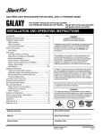
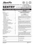
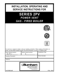
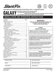
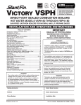
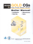
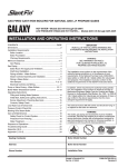
INSTALLATION, OPERATING AND
SERVICE INSTRUCTIONS FOR
SPACEMASTERTM
D I R EC T VEN T
N AT U R A L GAS - FI RED BOI LER
F o r s e r vi c e o r r e p a i r s to b o i le r, c a ll yo ur he a ti ng c o ntr a c to r. W he n s e e k i ng i nfo r m a ti o n o n
b o i le r, p r o vi d e B o i le r M o d e l Num b e r a nd S e r i a l Num b e r a s s ho wn o n Ra ti ng L a b e l.
B o i le r M o d e l Num b e r
S M_ _ - _ _ _ _ _
He a ti ng C o ntr a c to r
B o i le r S e r i a l Num b e r
Ins ta lla ti o n D a te
6_ _ _ _ _ _ _
P ho ne Num b e r
A d d re s s
8140312R13-6/06
Price - $3.00
IMPORTANT INFORMATION
PLEASE READ THIS PAGE CAREFULLY
This boiler has a limited warranty, a copy of which is
printed on the back page of this manual.
Post instructions near boiler for reference by owner and
serviceman.
All heating systems should be designed by competent
contractors and only persons knowledgeable in the
layout and installation of hydronic heating systems
should attempt installation of any boiler.
Maintain instructions in legible condition.
This equipment shall be installed in accordance with
those installation regulations in force in the area where
the installation is to be made. These shall be carefully
followed in all cases. Authorities having jurisdiction
shall be consulted before installations are made.
Boiler should be positioned to provide minimum side
clearances of 1”, minimum top clearance of 6”, minium
front clearance of 2”, minimum rear and flue system
clearances of 0” and minimum floor clearance of 6”
between boiler surfaces and any combustible materials.
(See Figure 3).
Boiler must also be positioned to provide minimum
clearances between edge of vent terminal and exterior
obstructions. Provide minimum overhang clearance
of 7”, minimum above grade clearance of 12” and
minimum side obstruction clearance of 18”. (See
Figure 2).
In all cases, clearance between boiler jacket and
vent system surfaces and combustible materials
must comply with the National Fuel Gas Code, ANSI
Z223.1, and local jurisdictions.
Keep boiler area clear and free from combustible
materials, gasoline and other flammable vapors and
liquids.
Do not place any obstruction in the boiler room that
will hinder the flow of ventilating air.
Boiler must be installed with the vent/intake air system
supplied as part of the unit, without alteration.
The wall thickness through which the unit may be
installed must not exceed a minimum of 5” or a
maximum of 15”.
a. Misc. Parts Carton — Part No. 6050301
(5” to 9” thick walls) — Standard
b. Misc. Parts Carton — Part No. 6050302
(9” to 15” thick walls) — Optional
The boiler shall be installed such that the gas ignition
system components are protected from water (dripping,
spraying, rain etc.). during boiler operation and service
(circulator replacement, control replacement, etc.).
It is the responsibility of the installing contractor to
see that all controls are operating properly when the
installation is completed.
Service on this boiler should be undertaken only by
trained and skilled personnel.
2
WARNING
W h e n a n e x is t in g b o ile r is r e m o v e d f r o m a
c o m m o n v e n t in g s y s t e m , t h e c o m m o n
v e n t in g s y s t e m is lik e ly t o b e t o o la r g e f o r
p r o p e r v e n t in g o f t h e a p p lia n c e s r e m a in i n g
c o n n e c t e d t o it .
a. Seal any unused openings in the common venting
system.
b. Visually inspect the venting system for proper
size and horizontal pitch and determine there is no
blockage or restriction, leakage, corrosion and other
deficiencies which could cause an unsafe condition.
c. Insofar as is practical, close all building doors and
windows and all doors between the space in which
the appliances remaining connected to the common
venting system are located and other spaces of the
building. Turn on clothes dryers and any appliance
not connected to the common venting system.
Turn on any exhaust fans, such as range hoods and
bathroom exhausts, so they will operate at maximum
speed. Do not operate a summer exhaust fan. Close
fireplace dampers.
d. Place in operation the appliance being inspected.
Follow the lighting instructions. Adjust thermostat
so appliance will operate continuously.
e. Test for spillage at the draft hood relief opening after
5 minutes of main burner operation. Use the flame
of a match or candle, or smoke from a cigarette,
cigar or pipe.
f. After it has been determined that each appliance
remaining connected to the common venting system
properly vents when tested as outlined above, return
doors, windows, exhaust fans, fireplace dampers and
any other gas burning appliance to their previous
conditions of use.
g. Any improper operation of the common venting
system should be corrected so the installation
conforms with the National Fuel Gas Code, ANSI
Z223.1. When resizing any portion of the common
venting system, the common venting system
should be resized to approach the minimum size as
determined using the appropriate tables in Part 11 in
the National Fuel Gas Code, ANSI Z223.1.
SPACEMASTER WALL MOUNTED GAS BOILER – DIMENSIONAL DATA
Figure 1
MAXIMUM DESIGN WORKING PRESSURE – 45 PSI; WATER ONLY
Table of Contents
I.
II.
III.
IV.
V.
VI.
General Installation Requirements ................... 4
Installation Instructions ..................................... 7
Operating Instructions ....................................... 13
Service ................................................................. 23
Repair Parts ........................................................ 26
APPENDIX
Low Water Cut Off............................................. 27
3
I. General Installation Requirements
1
INSPECT SHIPMENT carefully for any signs of
damage. All equipment is carefully manufactured,
inspected and packed. Our responsibility ceases upon
delivery of Boiler to the carrier in good condition. Any
claims for damage or shortage in shipment must be filed
immediately against the carrier by the consignee. No
claims for variances or shortages will be allowed by
Boiler Manufacturer, unless presented within sixty (60)
days after receipt of equipment.
2
BOILER INSTALLATION must conform to the
requirements of the authority having jurisdiction, or in
absence of such requirements to:
a. “National Fuel Gas Code, ANSI Z223.1 obtainable
from the American Gas Association, 1515 Wilson
Blvd. Arlington (Rosslyn), VA 22209.
b. When required by the authority having jurisdiction,
the installation must conform to American Society
of Mechanical Engineers Safety Code for Controls
and Safety Devices for Automatically Fired boilers,
No. CSD-1.
c. The boiler must be electrically grounded in
accordance with requirements of the authority
having jurisdiction or, in the absence of such
requirements, with the National Electrical Code,
ANSI/NFPA No. 70.
3
THESE GAS BOILERS ARE DESIGN
CERTIFIED FOR INSTALLATION on an exterior
wall of buildings constructed with combustible
materials (wood framed walls with, paneling, drywall,
plaster, etc.) or masonry walls (brick, stone, stucco, or
cinder block).
4
DO NOT INSTALL ON CARPETING. These gas
boilers may be installed above carpeted areas. Note:
Protect carpeting or flooring to avoid possible damage
during installation and maintenance procedures.
5
BOILER LOCATION MUST MEET THE
FOLLOWING SITE REQUIREMENTS:
a. The boiler must be mounted on a flat wall,
sufficiently strong enough to carry the weight of
the unit. (See Figure 1). Minimum acceptable wall
construction would consist of 2” x 4” studding on
24” centers. Unit is designed for installation on
16” centers. Therefore, adequate supports must be
added between existing studding.
b. A suggested mounting height, where practical, is
five feet - six inches from floor to center line of
intake air duct opening. (See Figure 1).
NOTE: depending on ceiling height, 6” combustible
clearance height from jacket top panel to ceiling
must be maintained. (See Figure 3).
c. Consider location of heating supply and return lines,
gas supply line, cold water piping and expansion
tank in selecting boiler location.
4
d. Exterior wall surface must be flat to ensure that wall
flange can be mounted without being distorted and
also provide a positive weather-tight seal to prevent
water damage.
If exterior wall surface is not flat (i.e., uneven
masonry, stucco, aluminum siding, etc.) a flat
surface must be provided of equal size or larger than
the exterior wall flange and vent terminal cover.
e. Locate the vent terminal in relation to adjacent
public walkways, adjacent buildings, operable
windows and buildings, consistent with the National
Fuel Gas Code Z223.1: Minimum clearance of
4 feet horizontally from and in no case above or
below (unless four [4] foot horizontal distance is
maintained), electric meters, gas meters, regulators
and relay equipment. At least 12” from any door,
window or other building opening. A minimum of
12” above grade, 7” from any overhang, 18” from
any side obstruction or wall and 3’ away from any
adjacent building. Increase minimum height above
grade to maintain adequate clearance above average
snow fall for geographical area in which unit is
installed. If the unit is to be vented over a public
walkway, it must be at least 7” above grade. If the
vent terminal is to be within 10’ of a building fresh
air intake, it must be at least 3’ above the opening.
In addition, avoid venting the unit in corners,
niches or areas which might have reduced fresh air
circulation. (See Figure 2).
Figure 2
f. If boiler is to be installed above the level of the
radiation, a low water cutoff must be installed.
6
PROVIDE CLEARANCE between boiler jacket,
mounting bracket and vent system and combustible
material in accordance with local fire ordinance.
a. Combustion air is provided 100% from the
outdoors. Air is pulled in on all four sides of vent
terminal cover, through the air intake duct and to
the combustion area enclosure. The vent terminal
must be mounted on a flat surface which is flush or
protrudes outward from the exterior wall. Avoid
recesses, niches or areas which might have reduced
fresh air circulation.
b. Ventilation — When the boiler is installed in
an unconfined space in a building of normal or
unusually tight construction, there is no additional
provision required to insure adequate air for
ventilation of the jacket or control compartment.
When the boiler is installed in a confined space,
two openings in a wall or door to an adjoining
interior area which has adequate air supply shall be
provided. One opening should be near the floor and
the other near the ceiling. Each shall have a free
area of not less than one (1) square inch for each
thousand (1000) BTU input to all appliances in the
boiler room. (See Figure 3).
8
Figure 3
** A minimum of 24” from left side and front jacket
panel is recommended for servicing.
MINIMUM CLEARANCE TO COMBUSTIBLE SURFACES
Minimum listed clearances from combustible materials
for non-closet installation or closet installation. (See
Figure 3).
Top — 6”
*Left Side —1”
Rear — 0”
Right Side — 1”
*Front — 2”
Flue — 0”
Floor — 6”
Since the above dimensions are measured between
boiler jacket and combustible walls or ceiling, practical
service clearances for all external adjoining equipment
must be considered (see Figure 1). * A minimum of 24”
from left side and front jacket panel is recommended for
servicing.
In utility room installations, the door must be wide
enough to allow boiler to enter or to permit replacement
of another appliance in this room.
7
VENTILATION AND COMBUSTION AIR.
Provide provisions for combustion and ventilation air
in accordance with Section 5.3, Air for combustion
and ventilation, of the National Fuel Gas Code, ANSI
Z223.1 or applicable provisions of local building codes.
This boiler is equipped with a fan which produces
an induced draft through the unit. Combustion air is
pulled in from outdoors and the flue gases are exhausted
to the outdoors through the intake air/vent system. (See
Figure 4).
CONNECT GAS SERVICE from meter to gas
control assembly in accordance with local piping codes
and requirements of gas company, see Figure 1. They
may require piping of larger size than 1/2” control
assembly connection, especially if run from meter is
long or includes several elbows.
This piping is to be supplied by the installer and must
include a trap, a ground joint union and a manual shutoff valve upstream of the gas control assembly outside
of the jacket when codes require, see Figure 1. A pipe
thread compound resistant to the action of liquefied
petroleum gases should be applied to all threaded joints
in the gas piping. Pressure testing of the gas supply
piping, boiler and its connections is required before
placing the boiler in operation.
The boiler must be isolated from the gas supply piping
system by closing the manual shut-off during any
pressure testing at pressures equal to or less than 1/2
psig.
The boiler and shut-off valve must be disconnected
from the gas supply piping system during any pressure
testing at pressures greater than 1/2 psig.
RECOMMENDED SIZING OF GAS SUPPLY
PIPING TO BOILER shall be such as to provide the
required supply of gas without undue loss of pressure
between meter and the boiler. Gas supply piping should
be sized in accordance with Tables, I, II and III.
The following shall be taken into account:
a. Allowable loss of pressure to assure a burner
manifold pressure of 3½” water.
b. Supply of gas to be provided in cubic feet.
c. Length of piping and number of fittings.
d. Specific gravity of gas.
e. Correction factor for specific gravity.
5
TABLE I
*NOTE – For all practical purposes, each 90° elbow
can be considered as the following equivalent in
length of straight pipe:
½” – 1.6 ft.
1” – 2.6 ft.
¾” – 2.1 ft.
M a xi m um C a p a c i ty o f P i p i ng i n C ub i c F e e t
o f Ga s P e r Ho ur
( B a s e d o n a P re s s ure D ro p o f 0 .3 " Wa te r
a nd 0 .6 S p e c i fi c Gra vi ty)
No m i na l Iro n P i p e S i ze
L e ng th i n
Feet
1 /2
3 /4
10
132
278
520
20
92
190
350
1
30
73
152
285
40
63
130
245
50
56
11 5
215
60
50
105
195
70
46
96
180
80
43
90
90
40
100
38
TABLE III
M ulti p li e rs to b e us e d wi th Ta b le s I a nd II fo r
S p e c i fi c Gra vi ty Othe r Tha n 0 .6 0
S p e c i fi c Gra vi ty
C o r r e c ti o n F a c to r s
.5 0
1 .1 0
170
.5 5
1 .0 4
84
160
.6 0
1 .0 0
79
150
.6 5
.9 6
.7 0
.9 3
TABLE II
M a xi m um C a p a c i ty o f P i p i ng i n C ub i c F e e t o f
Ga s P e r Ho ur
( B a s e d o n a P re s s ure D ro p o f 0 .5 " Wa te r a nd
0 .6 S p e c i fi c Gra vi ty)
6
No m i na l Iro n P i p e S i ze
L e ng th i n
Feet
1 /2
3 /4
1
10
175
360
680
20
120
250
465
30
97
200
375
40
82
170
320
50
73
151
285
60
66
138
260
70
61
125
240
80
57
11 8
220
90
53
11 0
205
100
50
103
195
125
44
93
175
150
40
84
160
175
37
77
145
II. Installation Instructions
DETERMINE BEST MOUNTING LOCATION for boiler which meets site requirements outlined in Section I, pages 4
through 6.
1 INSTALLING BOILER MOUNTING WALL
BRACKET (See Figure 5).
a. Locate wall bracket packed in miscellaneous parts
carton.
b. Hold wall bracket in desired location. On studded
walls, mounting bracket must be secured directly to
main vertical support studs. Interior wall coverings
such as paneling, plaster and drywall are not suitable
to support the unit’s weight. Place a 24” level
across top corners, adjust wall bracket until level.
Using the wall bracket as a template, mark the eight
(8) securing holes along the sides and the 4½” x
5¼” rectangular opening at the top. Remove wall
bracket from wall.
NOTE: The boiler mounting wall bracket is
suitable for two main methods of wall construction.
Masonry-built walls and stud-framed walls where
the main vertical support studs are on 16” centers
or alternately where adequate supports are added
between existing studs.
c. Drill eight (8) pilot holes, properly sized for the
fastener determined suitable for the type of wall
construction in the area where the boiler is to be
mounted (i.e., lag screw for wood, machine screw
with toggle for cinder block, etc.).
d. Before cutting rectangular opening on interior wall,
use a straight edge to draw an “X” inside the box
using the four (4) corners. Drill a hole in the center
of the “X” straight through the wall to the outside.
On the exterior wall draw a 4½” x 5¼” rectangular
box centered around the reference hole which
matches the rectangular box on the interior wall.
e. Cut along outside edge of lines on interior and
exterior surfaces of the wall and remove all
material within the rectangular box. Check the wall
penetration by inserting one-half of the telescoping
intake air duct through the opening. Remove any
jagged edges or webbing that prevents the duct from
penetrating through the wall or from being level.
Remove duct from wall penetration.
f. Lay the wall bracket face down. Apply a ¼” thick
bead of silicone rubber type caulking around the
rectangular opening approximately 1” from the
edge.
g. Reposition boiler mounting wall bracket on wall,
using a 24” level across top corners, level wall
bracket and secure to wall with suitable fasteners.
h. Attach lower R.S. jacket mounting bracket to right
side of boiler mounting wall bracket with sheet
metal screws provided. (See Figure 5)
2
INSTALLING BOILER AND INTERIOR
TELESCOPING INTAKE AIR DUCT
(See Figure 5)
a. Separate two halves of telescoping intake air duct.
Interior half of duct has a 1” wide rectangular gasket
flange with four (4) weld studs for attaching to
back plate of boiler. Exterior half of duct has the
9” square stainless steel wall flange for securing to
exterior wall. (See Figure 5)
NOTE: 1. Standard telescoping intake air duct,
part No. 6110301, is for wall thickness
from 5” to 9”.
NOTE: 2. Optional telescoping intake air duct, part
No. 6110302, is for wall thickness from
9” to 15”.
b. Insert interior half of duct into rectangular opening
and push it all the way back against wall plate.
c. Place 6” x 7” rectangular gasket on interior duct
flange and ¼” weld studs.
d. Remove boiler from packaging.
1. Remove surrounding packaging material from
boiler and skid.
2. Remove screws holding enclosure cover.
3. Remove enclosure cover.
4. Locate and remove two (2) lag screws which
secure back plate of boiler to skid. One is
located in the upper left corner of the controls
area and the second one is located in the lower
right corner under the gas burner.
5. Remove boiler from skid and set unit upright on
floor in front of installation site.
NOTE:
On the back plate of the boiler is a “Z”
bracket approximately 10” long. When
the boiler is lifted into place, this bracket
must be lowered into the ½” wide x 11”
long slot at the top of the boiler mounting
wall bracket. (See Figures 4 and 5)
e. Attach upper RS jacket mounting bracket to the
upper corner of back plate. Loosen the two (2)
corner screws, position bracket with flange facing
forward and engage slots over screws. Re-tighten
screws to secure bracket. IMPORTANT: Bracket
must be installed before lifting boiler into position.
f. Lift boiler up into position. Make sure that “Z”
bracket is properly engaged into slot and is resting
on ¼” wide flange in front of slot before releasing
the weight of the boiler.
g. Move boiler slightly to the left or right to align the
five (5) clearance holes in the back plate with the
fasteners on boiler mounting wall bracket.
7
h. Secure boiler to boiler mounting wall bracket with
five (5) ¼”-20 x ¾” long machine screws and
washers provided.
NOTE: Tools required — 7/16” socket, extension
bar(s) and drive ratchet
i. Secure interior telescoping intake air duct to
back plate of boiler. Pull duct forward until duct
and weld studs are engaged through 4½” x 5½”
rectangular opening and holes in back plate. Make
sure gasket is in place and flat against back plate.
Attach duct with four (4) ¼”-20 brass hex nuts,
lockwashers and flat washers.
3
INSTALLING EXTERIOR TELESCOPING
INTAKE AIR DUCT (See Figures 4 and 5)
a. Position the exterior telescoping intake air duct into
wall penetration and insert duct inside interior duct
already in place. Push duct inward until wall flange
is against the wall, check for level and mark the four
(4) ¼” diameter clearance holes for securing wall
flange to exterior wall. Remove duct from wall.
Figure 4
VENT SYSTEM CROSS SECTION
Figure 5
8
EXPLODED BOILER ASSEMBLY
b. Drill four (4) pilot holes, properly sized for the
non-corrosive fasteners (stainless steel, brass or
aluminum) to be used to secure the wall flange to
wall.
c. Attach four (4) ½” long threaded aluminum spacers
to the outer flanges of the exterior telescoping
intake air duct wall flange with four (4) #10-32 x
¼” long stainless steel machine screws provided.
(See Figure 5).
d. Apply a ¼” thick continuous bead of silicone rubber
type caulking to the rear of the exterior telescoping
intake air duct wall flange approximately 1” from
duct.
e. Re-install exterior telescoping intake air duct and
secure to wall.
NOTE: Non-corrosive (stainless steel, brass or
aluminum) fasteners must be used.
f. Apply a bead of silicone rubber caulking to
perimeter of wall flange, where the wall and flange
join. Use a tool or your finger and apply pressure
while smoothing caulking to provide a weather-tight
seal.
4
INSTALLING VENT TUBE, ORIFICE PLATE
AND VENT TERMINAL COVER (See Figures 4
and 5).
a. The vent tube furnished has a standard length of
24”. This length is suitable for a wall thickness
from 5” to 15”.
b. To determine the proper length required, place a 24”
level horizontally across the exterior wall flange,
just below the aluminum spacers, measure the
distance between the outlet flange on the fan and
the level. Add 1” to this measurement for the total
length of the vent tube.
c. Measuring from the flange end of the vent tube,
mark the total length required. Cut off and discard
the remaining piece.
d. IMPORTANT! Before connecting vent tube to fan,
install the orifice plate and two (2) cerafibre gaskets
on the fan outlet flange weld studs in the proper
order of assembly, gasket first, orifice plate second
and remaining gasket last. (See Figures 4 and 5).
e. Insert the vent tube, flange first, through the intake
air duct and secure to fan outlet flange with four (4)
¼” flat washers, ¼” lock washers and ¼”-20 brass
hex nuts provided.
f. Position vent terminal cover over exterior intake air
duct. Insert end of vent tube into collar on rear of
vent terminal cover. Align four (4) holes on cover
with ½” long threaded aluminum spacers. Secure
vent terminal cover with four (4) #10-32 x ¼” long
stainless steel machine screws provided.
5
DO NOT REPLACE ENCLOSURE COVER until
boiler piping is completed and system is filled, vented
and checked for water leaks.
6
CONNECT SUPPLY AND RETURN PIPING TO
heating system.
OXYGEN CORROSION:
Oxygen contamination of the boiler water will cause
corrosion of the iron and steel boiler components,
which can lead to failure. As such, any system must
be designed to prevent oxygen absorption in the first
place or prevent it from reaching the boiler. Problems
caused by oxygen contamination of boiler water are not
covered by Burnham’s standard warranty.
There are many possible causes of oxygen
contamination such as:
1. Addition of excessive make-up water as a result of
system leaks.
2. Absorption through open tanks and fittings.
3. Oxygen permeable materials in the distribution
system.
In order to insure long product life, oxygen sources
should be eliminated. This can be accomplished by
taking the following measures:
1. Repairing system leaks to eliminate the need for
addition of make-up water.
2. Eliminating open tanks from the system.
3. Eliminating and/or repairing fittings which allow
oxygen absorption.
4. Use of non-permeable materials in the distribution
system.
5. Isolating the boiler from the system water by
installing a heat exchanger.
a. For heating only, see Figure 6. Consult I=B=R
Installation Guides. Clearance between hot
water pipes and combustible material must not
be less than ½”.
b. If this boiler is used in connection with
refrigeration systems, the boiler must be installed
so that the chilled medium is piped parallel
with the heating boiler using appropriate valves
to prevent the chilled medium from entering
the boiler, see Figure 7. Also consult I=B=R
Installation and Piping Guides. If this boiler
is connected to heating coils located in air
handling units where they may be exposed
to refrigerated air, the boiler piping must be
equipped with flow control valves to prevent
gravity circulation of boiler water during the
operation of the cooling system.
c. Pipe safety relief valve to suitable drain.
CAUTION: Safety relief valve should be piped
to an open drain — full size of discharge outlet on
relief valve without any provision of “shut-off”
between the relief valve and discharge into drain.
d. Install diaphragm type expansion tank (not
furnished) in system piping.
9
e. A hot water boiler installed above radiation level
must be provided with a low water cutoff device
as part of the installation.
If a low water cut-off is required, it must be
mounted in the system piping above the boiler.
The minimum safe water level of a hot water
boiler is just above the highest water containing
cavity of the boiler; that is, a hot water boiler
must be full of water to operate safely.
f. Use a boiler bypass if the boiler is to be
operated in a system which has a large volume
or excessive radiation where low boiler water
temperature may be encountered (i.e., converted
gravity circulation system, etc.). The bypass
should be the same size as the supply and return
lines with valves located in the by-pass and
supply outlet as illustrated in order to regulate
water flow for maintenance of higher boiler
water temperatures. See Figure 6.
Set the by-pass and boiler supply valves to a
half throttle position to start. Operate boiler
until the system water temperature is at a normal
operating range.
Adjust the valves to provide 180° to 200°F
supply water temperature. Opening the boiler
supply valve will raise the system temperature,
while opening the by-pass valve will lower the
system supply temperature.
If it is required to perform a long term pressure
test of the hydronic system, the boiler should first
be isolated to avoid a pressure loss due to the
escape of air trapped in the boiler.
To perform a long term pressure test including
the boiler, ALL trapped air must first be removed
from the boiler.
A loss of pressure during such a test, with no
visible water leakage, is an indication that the
boiler contained trapped air.
7
INSTALL BOILER FLUSH JACKET (See Figure
9).
a. Open jacket carton and locate side panels. Note that
jacket left side panel is not insulated and right side
panel is insulated.
b. Position the rear flange on jacket left side panel
behind the boiler back plate. Position flange support
notches over jacket support hooks on back panel
and engage jacket on both support hooks to keep the
panel from moving front to rear.
c. Position rear flange on jacket right side panel behind
upper and lower jacket support brackets. Engage
jacket with jacket support hooks in similar manner
as left side panel to provide proper positioning and
support.
d. Take jacket top and bottom panel from carton. Top
panel can be identified by the front channel used to
Figure 6
RECOMMENDED BOILER PIPING
10
Figure 7
RECOMMENDED PIPING FOR COMBINATION HEATING & COOLING (REFRIGERATION) SYSTEMS
Figure 9
EXPLODED JACKET ASSEMBLY
11
support the removable door. (See Figure 9). Place
jacket top panel over top side panels with ventilation
louvers to the left. Secure top panel with four (4) #8
x ½” long sheet metal screws provided.
e. Lift jacket bottom panel up to bottom of side panels
with front channel forward and ventilation louvers
to the left. Secure bottom panel with four (4) #8 x
½” long sheet metal screws provided.
f. Install jacket removable door. Hold door parallel
with top of door slightly above flat top panel. Insert
door between side panels. Lower door engaging
top panel reverse bend and lower panel flange in
the mating door flanges. Door is now locked into
position.
g. Reverse procedure to remove door.
8
12
INSTALL ROOM THERMOSTAT on an inside
wall about four feet above floor. Never install
thermostat on an outside wall or where it will be
influenced by drafts, hot or cold water pipes, lighting
fixtures, television, rays of the sun or near a fireplace.
Keep large furniture away from thermostat so there will
be free movement of room air around this control.
Heat anticipator in thermostat should be set at .4.
9
ELECTRIC WIRING INSTALLATION.
See Figures 11 and 12 for applicable wiring
diagram. A separate electrical circuit must be run
from the main electrical service with an over-current
device/disconnect in the circuit. A service switch is
recommended and may be required by some local
jurisdictions. The circuit should be run to the junction
box mounted on the front of the boiler back plate in the
control compartment (See Figure 1), and connected to
the proper leads therein. Wires from the low voltage
thermostat should be run to terminals R and G on
the transformer. Install wiring and ground boiler in
accordance with requirements of authority having
jurisdiction, or in absence of such requirements the
National Electrical Code, ANSI/NFPA 70.
III. Operating Instructions
Safe lighting and other performance criteria were met with
the gas manifold and control assembly provided on the
boiler when the boiler underwent tests specified in ANSI
Z21.13.
1
INSPECT INSTALLATION BEFORE
STARTING.
2
INITIAL START
c. Be sure that gas to pilot and main burners has been
off for at least five minutes.
d. Open valve on main gas line at meter.
e. PURGE AIR FROM GAS PIPING. During the
purge adequate ventilation must be provided and no
smoking or open flame permitted. (See Figure 10)
1. Open manual shutoff valve upstream of
combination gas valve.
2. Loosen or remove inlet pressure tap plug in
combination gas valve and when purging is
complete, tighten or replace plug.
3. Check pipe and fittings from meter to
combination gas valve using soap solution or
other approved methods.
f. TEST GAS PIPING — Test gas piping and
connections between combination gas valve and
manifold, manifold orifices, and pilot piping for
leaks after boiler is operating. Use soap solution or
other approved method.
a. FILL ENTIRE HEATING SYSTEM WITH
WATER and vent air from system. Vent air from
all heat distributing units and all high points in the
piping of the system. When venting air from system
keep fill valve in open position to maintain water
pressure. Make certain pressure reducing valve is
installed between the fill valve and the boiler. (See
Figure 7)
Use the following procedure on a series loop system
equipped with zone valves.
1. Close all but one zone valve.
2. Attach a hose to drain valve on purge fitting and
extend hose to drain.
3. Open drain valve on purge fitting.
4. Close purge valve.
5. Open relief valve on boiler.
6. Open fill valve.
7. When water discharges from relief valve, release
the lever on top of the relief valve, allowing it to
close.
8. Allow water to run out of drain valve until zone
has been purged of air and filled with water.
9. Open zone valve to the second zone to be
purged, then close the first. Repeat this step until
all zones have been purged but always have one
zone open. At completion open all zone valves.
10. Close drain valve on purge fitting.
11. Continue filling the system until the pressure
gauge reads 12 psi. Close fill valve.
NOTE: If make-up water line is equipped
with pressure reducing valve, system will
automatically fill to the set pressure of valve
(normally 12 psi). Leave globe valve open.
12. Open purge valve.
b. Set ROOM THERMOSTAT below room
temperature.
g. Install enclosure cover and secure with #8 x ½” long
sheet metal screws.
3
OPERATING INSTRUCTIONS - See page 14.
Figure 10
SCHEMATIC PILOT AND GAS PIPING
13
NOTE: YOUR BOILER IS EQUIPPED WITH A HONEYWELL VR8204 OR VR8304 GAS VALVE. PLEASE
FOLLOW
THESE OPERATING INSTRUCTIONS:
14
15
Figure 11
SCHEMATIC WIRING DIAGRAM
Figure 12
LADDER WIRING DIAGRAM
16
SEQUENCE OF OPERATION
1. When the thermostat calls for heat, relay coil (1M)
is energized closing two sets of NO contacts. One
set (1M2) energizes the 24 volt limit circuit and the
other set (1M1) completes the 120 volt circulator
circuit.
2. With the thermal cutout switch (on the burner
access panel), the high limit switch, and the suction
pressure switch in their normally closed positions,
the fan relay coil (2M) is energized closing two sets
of NO contacts. One set (2M1) completes the 120
volt fan circuit and the other set (2M2) energizes the
24V suction pressure “check” circuit.
3. With the fan operating, the suction pressure switch
closes its NO contacts. The “check” circuit contacts
(2M2) keep power on the fan relay (2M) during the
heating cycle.
4. When the suction pressure switch proves fan
operation the ignition module is energized,
beginning a 30-50 second prepurge. During
prepurge the module performs a safe-start check
that tests the internal components of the module for
a flame simulating condition. If a flame simulating
condition is present in the module, the heating
system will not start.
5. After prepurge, the module energizes the pilot gas
valve operator. The pilot gas valve opens, allowing
gas to flow to the pilot burner. At the same time, the
electronic spark generator in the module generates a
spark at the ignitor-sensor to light the pilot.
6. If the pilot does not light within 90 seconds, or the
pilot flame current is not at least 1.0 milliamps and
steady, the module will not energize the main gas
valve and the main burner will not light. Then the
module goes into safety lockout, de-energizing the
pilot gas valve operator causing the pilot gas valve
to close. Five to six minutes after shutdown, the
Ignition Module restarts the ignition sequence.
7. When the sensor senses pilot flame during the 90
second trial for ignition the module will shut off the
spark generator, reset the safety lockout timer, and
energize the main gas valve operator. The main gas
valve opens allowing gas to flow to the main burners
where it is ignited by the pilot burner. Since the
main gas valve is a step-opening valve, a limited
amount of gas will be admitted to main burners
for ignition (low fire). After a short time interval,
the regulator on the gas valve will permit full flow
through the main gas valve (high fire).
Should a loss of flame occur, the main valve closes
and the spark reoccurs within 0.8 second. The
ignition module has an internal 100% lockout
function to completely shutdown the system should
the pilot gas fail to ignite with approx. 90 seconds.
Five to six minutes after shutdown, the Ignition
Module restarts the ignition sequence. The ignition
trial, shutdown, and wait sequence continues until
either the pilot lights or the Thermostat is set below
room temperature (to end the call for heat). The
ignition sequence can be reset by setting down the
Thermostat for one minute.
8. Burners, circulator and fan will continue to operate
until the thermostat is satisfied.
9. If the high limit setting is reached before the
thermostat is satisfied, the switch in the high limit
will open to de-energize the ignition module and
fan relay coil (2M), causing the gas valves to close
and the fan to stop. (The circulator will continue
to operate as long as the thermostat is calling for
heat). When the boiler water temperature drops to
a point where the high limit switch closes, the fan
will restart (via 2M) and the ignition module will be
energized to repeat the sequence in Steps 4 through
7 above.
10. If for any reason (such as flame roll out into the
vestibule) the thermal cutoff switch located on the
burner access panel is subjected to temperatures
above its setting the TCO switch will open to
de-energize the ignition module and fan relay coil
(2M), causing the gas valves to close and the fan to
stop. (The circulator will continue to operate as long
as the thermostat is calling for heat). Since the TCO
switch is a one-time fusible link, the reason for overheating must be determined and the switch replaced
in order for the boiler to function again.
11. In the event the fan is inoperative or fails to provide
sufficient air flow, the suction pressure switch
connected at the inlet of the fan will not activate, the
NO contacts will not close, the ignition module will
not be energized, and hence the gas valves cannot be
opened.
12. If the contacts in the suction pressure switch were
to weld together during the heating cycle (COM to
NO), the ignition module could not be energized
on the next call for heat due to the fact the fan relay
coil (2M) could not be energized through either the
suction pressure switch or the now open “check
circuit” contacts.
17
TROUBLE SHOOTING
Use the Trouble Shooting Guide (pages 19 to 21) to
assist in locating where a malfunction in the control
system is occurring.
4
PROCEDURE FOR MEASURING FAN
DIFFERENTIAL PRESSURE (See Figure 13).
a. With boiler off, remove black silicone tubing from
low side of pressure switch.
b. With tee and ¼” aluminum stubs, connect
manometer as shown with additional tubing.
c. Start boiler and read differential pressure on
manometer. Should be -0.6” wc or greater (example
-0.7” wc).
d. Stop boiler, remove manometer and reconnect black
silicone tubing to duct.
5
flow (cu. ft.) should be in 3 minutes using formula
below:
cu. ft. per = Btuh Input (from Rating Label)
3 min. =
20000
Clock gas meter for three (3) minutes using second
hand or stop watch.
For minor input changes readjust pressure regulator
on combination gas control. Increase or decrease
manifold pressure to obtain corresponding increase
or decrease in gas input.
Turning regulator adjusting screw clockwise
increases pressure. Counterclockwise rotation
decreases pressure. If it is necessary to increase
manifold pressure more than 0.3” of water to obtain
rated input, remove orifices and drill one size larger.
Reinstall and recheck input rate.
CHECK GAS INPUT RATE TO BOILER
a. Input rate and maximum inlet pressure shown on
rating label must not be exceeded. Inlet pressure
must not be lower than minimum inlet pressure
shown on rating label.
b. All rate checks and all adjustments are to be made
while boiler is firing - all other appliances connected
to the same meter as the boiler must be off.
c. Water manometer or water column gauge should
be connected to a shutoff valve installed in the
1/8” pipe tapping in the gas valve - boiler off. By
installing gas valve up stream of manometer, gas
pressure can be introduced gradually - without
shutoff valve, surge of pressure when boiler is
turned on, could blow liquid out of manometer.
Replace plug in gas valve when rate check is
finished.
d. Approximate input - Adjust pressure regulator on
combination gas control so that manifold pressure is
equal to that shown on rating label. Determine what
18
Figure 13
PROCEDURE FOR MEASURING FAN DIFFERENTIAL
PRESSURE
19
20
21
6
7
8
9
10 MAIN BURNER FLAMES should have a clearly
CHECK PILOT FLAME. Flame should be a blue
medium hard flame enveloping approximately 3/8” of
the end of the sensing probe, see Figure 14.
defined inner cone, see Figure 15, with no yellow
tipping. Orange-yellow streaks caused by dust should
not be confused with true yellow tipping.
CHECK THERMOSTAT OPERATION. Raise and
lower thermostat setting as required to start and stop
burners.
11 CHECK LWCO OPERATION (if so equipped). Drain
CHECK HIGH LIMIT CONTROL. Allow boiler to
operate until burners are shut down by limit control
(approximately 235°F). If burners are not shut down by
limit control, determine cause of malfunction. Replace
control if necessary and check its operation.
12 WARNING – BEFORE INSTALLATION OF THE
boiler water below LWCO set point. Burners should
shutdown. If burners do not shut down determine cause
of malfunction and repair.
CHECK IGNITION SYSTEM SAFETY SHUTOFF
DEVICE. Remove pilot ground lead from electrical
junction block. If burners are not shut down by
module, determine cause of malfunction. Replace
module or gas valve if necessary.
BOILER IS CONSIDERED COMPLETE, THE
OPERATION OF THE BOILER CONTROLS
SHOULD ALL BE CHECKED, PARTICULARLY
THE LOW WATER CUT-OFF AND THE HIGH
LIMIT CONTROL.
Figure 14
TYPICAL PILOT FLAME
Figure 15
MAIN BURNER FLAME
22
IV. Service
1
GENERAL — Inspection should be conducted
annually. Service as frequently as specified in
paragraphs below. While service or maintenance is
being done, Electrical Power and all Gas Supply to the
Boiler must be “off.”
brush flueways thoroughly from top of boilers as
illustrated in Figure 16. Replace canopy and seal.
4
BURNERS AND FIREBOX SHOULD BE
CLEANED ANNUALLY
a. Remove jacket front panel.
CAUTION
b. Remove sheet metal screws securing enclosure
cover and remove cover exercising care with gasket.
L a b e l a ll w ir e s p r io r to d is c o n n e c tio n w h e n
s e r v ic in g c o n tr o ls . W ir in g e r r o r s c a n c a u s e
i m p r o p e r a n d d a n g e r o u s o p e r a t i o n . Ve r i f y
p r o p e r o p e r a tio n a fte r s e r v ic in g .
2
c. Remove TCO leads from TCO and remove burner
access panel.
d. Brush top of burner with a soft bristle brush and
vacuum burner, see Figure 16. Check orifice to see
that drilled passageway is free of lint and dirt.
VENT SYSTEM — Vent system (see Figure 4 for
typical installation) should be checked annually for:
e. Vacuum tips of pilot burner.
a. Obstructions
f. Clean firebox by vacuuming. Exercise care not to
disturb insulation inside base.
b. Accumulations of soot
c. Deterioration of vent pipe or vent accessories due to
condensation or other reasons
5
a. Disconnect pilot tubing coupling, ignition cable and
ground wire from pilot assembly.
d. Proper attachment of vent cap and sealant around
wall penetration
b. Disconnect gas valve at union between valve and
bulkhead penetration.
e. Remove vent cap and clean accumulations of
soot and dirt with wire brush and vacuum. See
Figure 16. Remove any obstructions. Replace all
deteriorated parts.
3
REMOVAL OF BURNER ASSEMBLY
c. Remove two fasteners attaching burner to bulkhead
and single fastener for burner end support.
d. Grasp burner, tilt upward and remove from unit.
CLEANING BOILER FLUES (See Figure 16).
Flue passageways in the boiler sections should be
checked annually for any blockage or accumulation of
soot. To obtain access to flueways:
e. INSTALL BURNER by reversing procedure used
to remove.
6
a. Remove jacket front panel.
a. If pilot assembly, sensor or pilot orifice need
replacement, remove jacket front panel, enclosure
cover and burner access panel using procedure
described in paragraph 4 above.
b. Remove sheet metal screws securing combustion
area enclosure cover and remove cover. Exercise
care when removing to prevent damage to enclosure
gasket.
b. Disconnect pilot tubing, ground wire and ignition
sensor cable.
c. Remove fan assembly after disconnecting electrical
leads and vent tube. Care should be exercised to
avoid damage to gaskets.
c. Remove two machine screws holding pilot burner to
pilot bracket.
d. Remove four (4) bolts securing canopy and remove
canopy — flueways are now exposed.
Using a flashlight, examine all flue passageways.
If passageways are free of soot and obstruction,
replace canopy, secure and seal using kit available
from Burnham distributors.
e. Replace fan, connect vent tube and electrical wiring.
f. Reinstall and secure enclosure cover and jacket front
panel.
If the flue passageways need cleaning, remove
burners as described in paragraph 4 below. Using
long handle wire or bristle flue brush and vacuum,
REMOVAL OR REPLACEMENT OF PILOT
ASSEMBLY OR PILOT ASSEMBLY PARTS
d. Reinstall pilot burner by reversing above procedure.
e. Check pilot and main burner flames, refer to Figures
14 & 15.
7
CHECK MAIN BURNER AND PILOT FLAMES,
refer to Section III, paragraphs 6 and 10.
8
CHECK ALL CONTROLS ANNUALLY, see
procedure in Section III, paragraphs 7, 8, 9, 11 and 12.
MAINTENANCE OF LOW WATER CUTOFF
— During the heating season, if an external float type
low water cutoff is on the boiler, the blow off valve
should be opened once a month (use greater frequency
23
where conditions warrant) to flush out the sediment
chamber so the device will be free to function properly.
Low water fuel cutoffs and water feeders should be
dismantled annually by qualified personnel, to the
extent necessary to insure freedom from obstructions
and proper functioning of the working parts. Inspect
connecting lines to boiler for accumulation of mud,
scale, etc. and clean as required. Examine all visible
wiring for brittle or worn insulation and make sure
electrical contacts are clean and that they function
properly. Give special attention to solder joints on
bellows and float when this type of control is used.
Check float for evidence of collapse and check mercury
bulb (where applicable) for mercury separation or
discoloration. Probe type low water cutoff should be
removed once a year, examined and cleaned of any
dirt accumulations to assure proper operation. Do not
attempt to repair mechanisms in the field. Complete
replacement mechanisms including necessary gaskets
and installation instructions are available from the
manufacturer.
9
LUBRICATION
There are no parts requiring lubrication on the part of
the serviceman or the homeowner. Circulator bearings
are water lubricated. Fan motor bearings are factory
sealed.
Figure 16
CLEANING OF VENT SYSTEM, BOILER FLUES, AND BURNERS
24
Im p o r t a n t P r o d u c t S a fe t y In fo r m a t io n
R e fr a c t o r y C e r a m ic F ib e r P r o d u c t
Warning:
This product contains refractory ceramic fibers (RCF). RCF has been classified
as a possible human carcinogen. After this product is fired, RCF may, when
exposed to extremely high temperature (>1800F), change into a known human
carcinogen. When disturbed as a result of servicing or repair, RCF becomes
airborne and, if inhaled, may be hazardous to your health.
AVOID Breathing Fiber Particulates and Dust
Precautionary Measures:
Do not remove or replace previously fired RCF (combustion chamber insulation,
target walls, canopy gasket, flue cover gasket, etc.) or attempt any service or
repair work involving RCF without wearing the following protective gear:
1. A National Institute for Occupational Safety and Health (NIOSH)
approved respirator
2. Long sleeved, loose fitting clothing
3. Gloves
4. Eye Protection
•
•
•
•
Take steps to assure adequate ventilation.
Wash all exposed body areas gently with soap and water after contact.
Wash work clothes separately from other laundry and rinse washing
machine after use to avoid contaminating other clothes.
Discard used RCF components by sealing in an air tight plastic bag.
First Aid Procedures:
•
•
•
•
If contact with eyes: Flush with water for at least 15 minutes. Seek
immediate medical attention if irritation persists.
If contact with skin: Wash affected area gently with soap and water.
Seek immediate medical attention if irritation persists.
If breathing difficulty develops: Leave the area and move to a
location with clean fresh air. Seek immediate medical attention if
breathing difficulties persist.
Ingestion: Do not induce vomiting. Drink plenty of water. Seek
immediate medical attention.
25
V. Repair Parts
All Spacemaster™ Repair Parts may be obtained through your local Burnham Wholesale
distributor. Should you require assistance in locating a Burnham distributor in your area, or
have questions regarding the availability of Burnham products or repair parts, please contact
Burnham Customer Service at (717) 481-8400 or Fax (717) 481-8408.
A ny p a r ts no t li s te d c a n b e o r d e r e d b y d e s c r i p ti o n o r p a r t num b e r o n the i te m .
Part No.
81660145U
1.
Ga s Va lve - Ho ne ywe ll V R8 2 0 4 C 3 0 0 7
2.
Ig ni ti o n M o d ule - Ho ne ywe ll S 8 6 7 0 E 1 0 0 7 *
80160108
3.
D i ffe re nti a l P re s s ure S wi tc h
60160880
4.
Hi g h L i mi t - Ho ne ywe ll L 4 1 8 9 B 2 0 1 2
80160460
4 a . Ho ne ywe ll # 4 5 9 0 0 4 0 9 -0 0 3 B Imme rs i o n W e ll (½" NP T)
80160461
5.
C i rc ula to r - TA C O # 0 0 5 -T1
8056054
6.
P i lo t - Ho ne ywe ll Q3 6 2 A 1 0 3 7
8236068
7.
Ig ni ti o n/S e ns o r C a b le Ho ne ywe ll 3 9 4 7 9 9 -3 6
8236085
8 a . M a i n Ga s B urne r wi th P i lo t B ra c k e t a nd Ori fi c e # A B 2 4 0 4 0 (3 s e c ti o n)
8236070
8 b . M a i n Ga s B urne r wi th P i lo t B ra c k e t a nd Ori fi c e # A B 2 4 0 4 2 (4 s e c ti o n)
8236074
Ind uc e d D ra ft F a n Re p la c e me nt A s s e mb ly - Inc lud e s F a n (8 11 6 0 5 5 ),
C a no p y Outle t Ga s k e t, F a n Inle t Ga s k e t a nd two (2 ) F a n Outle t Ga s k e ts
6 11 0 3 0 3
10.
F a n Inle t C a s ti ng
8 11 6 0 5 6
11 .
Te mp e ra ture /P re s s ur e Ga ug e
8056235
9.
1 2 a . L o we r C i rc ula to r Re turn P i p i ng A s s e mb ly - 3 s e c ti o n
8060301
1 2 b . L o we r C i rc ula to r Re turn P i p i ng A s s e mb ly - 4 s e c ti o n
8060305
1 3 a . S up p ly P i p i ng A s s e mb ly - 3 s e c ti o n
8060302
1 3 b . S up p ly P i p i ng A s s e mb ly - 4 s e c ti o n
8060304
14.
Up p e r C i rc ula to r Re turn P i p i ng A s s e mb ly
8060303
15.
E nc lo s ure Ga s k e t
8200301
16.
C a no p y Outle t Ga s k e t
8206034
17.
F a n Inle t Ga s k e t
8 2 0 6 0 11
18.
F a n Outle t/Ori fi c e P la te Ga s k e t (2 re q ui re d )
8200306
19.
Tra ns fo rme r/Re la y C o mb i na ti o n - Ho ne ywe ll R8 2 8 5 D 5 0 0 1
80160156U
20.
Re la y - Ho ne ywe ll R8 2 2 2 U1 0 0 6
80160096U
21.
M i s c . P a rts C a rto n 5 " to 9 " thi c k wa lls
6050301
22.
M i s c . P a rts C a rto n 9 " to 1 5 " thi c k wa lls
6050302
23.
Ve nt Tub e - 2 ½" O.D . x 2 4 " L g .
8 11 0 3 0 1
24.
Ve nt Tub e M o unti ng F la ng e
7 11 0 3 11
2 5 a . O r i f i c e P la t e - 3 s e c t i o n
6 11 0 3 0 3 6
2 5 b . O r i f i c e P la t e - 4 s e c t i o n
6 11 0 3 0 4 6
26.
A i r Inle t D uc t Ga s k e t
8200307
27.
F la me Ro ll-Out S wi tc h
80160044
* WARNING — The Honeywell S8670E Ignition Module incorporates a prepurge feature that is necessary for
the safe operation of this boiler. Do not substitute any other Ignition Module.
26
VI. Low Water Cut Off (LWCO)
WAR N IN G
D O N OT AT T E M P T to c u t fa c to r y w ir e s to in s ta ll a n a fte r m a r k e t L o w Wa te r C u t Off (LW C O).
On ly u s e c o n n e c tio n s s p e c ific a lly id e n tifie d fo r L o w Wa te r C u t Off.
In a ll c a s e s , fo llo w th e L o w Wa te r C u t Off (LW C O) m a n u fa c tu r e r ' s in s tr u c tio n s .
When
A low water cutoff is required to protect a hot water
boiler when any connected heat distributor (radiation)
is installed below the top of the hot water boiler (i.e.
baseboard on the same floor level as the boiler). In
addition, some jurisdictions require the use of a LWCO
with a hot water boiler.
Where
The universal location for a LWCO on both gas and oil
hot water boilers is above the boiler, in either the supply
or return piping. The minimum safe water level of a
water boiler is at the uppermost top of the boiler; that is,
it must be full of water to operate safely.
What Kind
Typically, in residential applications, a probe type
LWCO is used instead of a float type, due to their
relative costs and the simplicity of piping for a probe
LWCO.
draining the heating system. Many probe LWCO
manufacturers recommend an annual inspection of the
probe.
How to Wire
LWCO’s are available in either 120 VAC or 24 VAC
configurations. The 120 VAC configuration can be
universally applied to both gas and oil boilers by wiring
it in the line voltage service to the boiler (after the
service switch, if so equipped).
The presence of water in a properly installed LWCO
will cause the normally open contact of the LWCO to
close, thus providing continuity of the 120 VAC service
to the boiler.
It is recommended to supply power to the probe LWCO
with the same line voltage boiler service as shown
below.
How to Pipe
A “tee” is commonly used to connect the probe LWCO
to the supply or return piping, as shown below.
LWCO Location
Select the appropriate size tee using the LWCO
manufacturer’s instructions. Often, the branch
connection must have a minimum diameter to
prevent bridging between the probe and the tee. Also,
the run of the tee must have a minimum diameter to
prevent the end of the probe from touching or being
located too close to the inside wall of the run of the tee.
Ideally, manual shutoff valves should be located
above the LWCO and the boiler to allow for servicing.
This will allow probe removal for inspection without
Wiring of Typical LWCO
A 24 VAC LWCO is used primarily for gas fired
boilers where a 24 volt control circuit exists within the
boiler. However, a 24 VAC LWCO can only be used
if the boiler manufacturer has provided piping and
wiring connections and instructions to allow for this
application.
How to Test
Shut off fuel supply. Lower water level until water
level is BELOW the LWCO. Generate a boiler demand
by turning up thermostat. Boiler should not attempt to
operate. Increase the water level by filling the system.
The boiler should attempt to operate once the water
level is above the LWCO.
27
Limited Warranty
FOR RESIDENTIAL CAST IRON WATER BOILERS
Subject to the terms and conditions set forth below, U.S. Boiler
Co., Inc. Lancaster, Pennsylvania hereby extends the following limited
warranties to the original owner of a residential grade water boiler
manufactured and shipped on or after July 1,1991:
ONE YEAR LIMITED WARRANTY
ON RESIDENTIAL GRADE WATER BOILERS
U.S. Boiler Co., Inc. warrants to the original owner that its residential
grade water boilers comply at the time of manufacture with recognized
hydronic industry standards and requirements then in effect and will be
free of defects in material and workmanship under normal usage for a
period of one year from the date of original installation. If any part of a
water boiler is found to be defective in material or workmanship during
this one year period, U.S. Boiler Co., Inc. will, at its option, repair or
replace the defective part.
LIFETIME LIMITED WARRANTY ON HEAT EXCHANGER
U.S. Boiler Co., Inc. warrants to the original owner that the heat
exchanger of its residential grade water boilers will remain free from
defects in material and workmanship under normal usage for the
lifetime of the original owner at the original place of installation. If a
claim is made under this warranty during the first ten years from the
date of original installation, U.S. Boiler Co., Inc. will, at its option, repair
or replace the heat exchanger. If a claim is made under this warranty
after the expiration of ten years from the date of original installation,
U.S. Boiler Co., Inc. will, at its option and upon payment of the pro-rated
service charge set forth below, repair or replace the heat exchanger.
The service charge applicable to a heat exchanger warranty claim is
based upon the number of years the heat exchanger has been in service
and will be determined as a percentage of the retail price of the heat
exchanger model involved at the time the warranty claim is made as
follows:
Years
In Service
Service Charge
as % of
Retail Price
Years
In Service
Service Charge
as % of
Retail Price
1-10
11
12
13
14
15
16
17
No
Charge
5
10
15
20
25
30
35
18
19
20
21
22
23
24
25 and
above
40
45
50
55
60
65
70
75
NOTE: If the heat exchanger model involved is no longer available due to
product obsolescence or redesign, the value used to establish the retail
price will be the published price as shown in the Burnham Hydronics
Repair Parts Price Sheet where the heat exchanger last appeared or the
current retail price of the then nearest equivalent heat exchanger.
ADDITIONAL TERMS AND CONDITIONS
1. Applicability: The limited warranties set forth above are extended
only to the original owner at the original place of installation within the
United States and Canada. These warranties are applicable only to
water boilers designated as residential grade by U.S. Boiler Co., Inc. and
installed in a single or two-family residence and do not apply to steam
boilers of any kind or to commercial grade boilers.
2. Components Manufactured by Others: Upon expiration of the
one year limited warranty on residential grade water boilers, all boiler
components manufactured by others but furnished by U.S. Boiler Co.,
Inc. (such as oil burner, circulator and controls) will be subject only to the
manufacturer’s warranty, if any.
3. Proper Installation: The warranties extended by U.S. Boiler Co., Inc.
are conditioned upon the installation of the residential grade water boiler
in strict compliance with U.S. Boiler Co., Inc. installation instructions.
U. S. Boiler Co., Inc. specifically disclaims liability of any kind caused by
or relating to improper installation.
4. Proper Use and Maintenance: The warranties extended by U.S. Boiler
Co., Inc. conditioned upon the use of the residential grade water boiler
for its intended purposes and its maintenance accordance with U. S.
Boiler Co., Inc. recommendations and hydronics industry standards.
These warranties will be inapplicable if the residential grade water boiler
is used or operated over its rated capacity, is subjected to unauthorized
modification, or is damaged as a result of being otherwise improperly
operated or serviced including, but not limited to, damage from any of the
following: operation with insufficient water, allowing the boiler to freeze,
subjecting the boiler to flood conditions, and operation with unapproved
water or fuel additives which cause deposits or corrosion.
5. Removal and Installation: These warranties do not cover expenses
of removal or reinstallation. The owner is responsible for the cost of
removing and reinstalling any defective part and its replacements and all
labor and material connected therewith.
6. Exclusive Remedy: U.S. Boiler Co., Inc. obligation for any breach of
these warranties is limited to the repair or replacement of its parts in
accordance with the terms and conditions of these warranties.
7. Limitation of Damages: Under no circumstances shall U.S. Boiler Co.,
Inc. be liable for incidental, indirect, special or consequential damages
of any kind whatsoever under these warranties, including, but not limited
to, injury or damage to persons or property and damages for loss of use,
inconvenience or loss of time. U.S. Boiler Co., Inc. liability under these
warranties shall under no circumstances exceed the purchase price paid
by the owner for the residential grade water boiler involved. Some states
do not allow the exclusion or limitation of incidental or consequential
damages, so the above limitation or exclusion may not apply to you.
8. Limitation of Warranties: These warranties set forth the entire
obligation of U.S. Boiler Co., Inc. with respect to any defect in a
residential grade water boiler and U.S. Boiler Co., Inc. shall have no
express obligations, responsibilities or liabilities of any kind
whatsoever other than those set forth herein. These warranties are given
in lieu of all other express warranties.
ALL APPLICABLE IMPLIED WARRANTIES, IF ANY, INCLUDING
ANY WARRANTY OF MERCHANTABILITY OR FITNESS FOR A
PARTICULAR PURPOSE ARE EXPRESSLY LIMITED IN DURATION TO
A PERIOD OF ONE YEAR EXCEPT THAT IMPLIED WARRANTIES, IF
ANY, APPLICABLE TO THE HEAT EXCHANGER IN A RESIDENTIAL
GRADE WATER BOILER SHALL EXTEND TO THE ORIGINAL OWNER
FOR THE LIFETIME OF THE ORIGINAL OWNER AT THE ORIGINAL
PLACE OF INSTALLATION. SOME STATES DO NO ALLOW LIMITATION
ON HOW LONG AN IMPLIED WARRANTY LASTS, SO THE ABOVE
LIMITATION MAY NOT APPLY TO YOU.
PROCEDURE FOR OBTAINING WARRANTY SERVICE
In order to assure prompt warranty service, the owner is requested to
complete and mail the attached Warranty Card within ten days after the
installation of the boiler, although failure to comply with this request will
not void the owner’s rights under these warranties.
Upon discovery of a condition believed to be related to a defect in
material or workmanship covered by these warranties, the owner should
notify the installer, who will in turn notify the distributor. If this action is
not possible or does not produce a prompt response, the owner should
write to U.S. Boiler Co., Inc., Burnham Hydronics, at P.O. Box 3079,
Lancaster, PA 17604, giving full particulars in support of the claim.
The owner is required to make available for inspection by U.S.
Boiler Co., Inc. or its representative the parts claimed to be defective
and, if requested by U.S. Boiler Co., Inc. to ship these parts prepaid to
U.S. Boiler Co., Inc. at the above address for inspection or repair. In
addition, the owner agrees to make all reasonable efforts to settle any
disagreement arising in connection with a claim before resorting to legal
remedies in the courts.
THIS WARRANTY GIVES YOU SPECIFIC LEGAL RIGHTS AND YOU
MAY ALSO HAVE OTHER RIGHTS WHICH VARY FROM STATE TO
STATE.
03/03