1
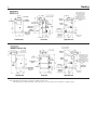
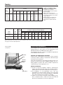
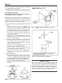
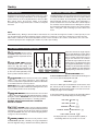
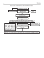
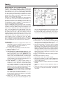
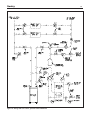
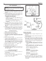
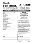
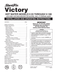
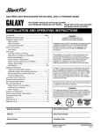
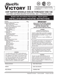
GAS-FIRED CAST-IRON BOILERS FOR NATURAL AND L.P. PROPANE GASES
SENTRY
®
This manual must be left with
owner and should be hung on or
adjacent to the boiler for reference.
HOT WATER MODELS S-34 THROUGH S-150
INSTALLATION AND OPERATING INSTRUCTIONS
CONTENTS. . . . . . . . . . . . . . . . . . . . . . . . . . . . . . . . PAGE
IMPORTANT
Dimensions . . . . . . . . . . . . . . . . . . . . . . . . . . . . . . . . . . 2,3
Installation Requirements:
Boiler Location . . . . . . . . . . . . . . . . . . . . . . . . . . . . . . . 3
Boiler Foundation . . . . . . . . . . . . . . . . . . . . . . . . . . . . . 3
Chimney Requirements . . . . . . . . . . . . . . . . . . . . . . . . 4
Minimum Clearance . . . . . . . . . . . . . . . . . . . . . . . . . . . 4
Vent Piping . . . . . . . . . . . . . . . . . . . . . . . . . . . . . . . . . . 4
Vent Damper Installation . . . . . . . . . . . . . . . . . . . . . . . 5
Gas Piping . . . . . . . . . . . . . . . . . . . . . . . . . . . . . . . . . . 6
Electrical Controls and Wiring. . . . . . . . . . . . . . . . . 6-10
Boiler Water Temperature Control. . . . . . . . . . . . . 10-15
Sequence of Operation . . . . . . . . . . . . . . . . . . . . . . . 16
Boiler Room Air Supply and Ventilation . . . . . . . . . . . 17
Water Piping at Boiler . . . . . . . . . . . . . . . . . . . . . . . . 17
Operating Instructions:
Filling and Venting Water Systems. . . . . . . . . . . . . . . 17
Initial Start:
Safety Information and Lighting Instruction . . . . . . . . 20
Burner Adjustment, Checking Gas Input . . . . . . . 20-21
Care and Maintenance
General Maintenance. . . . . . . . . . . . . . . . . . . . . . . . . 21
Water Level Check . . . . . . . . . . . . . . . . . . . . . . . . . . . 22
Annual Inspection and Cleaning . . . . . . . . . . . . . . . . 22
Safety Check for Control Systems . . . . . . . . . . . . . . . 22
Protection from Freezing/Water Treatment. . . . . . . . . 22
Keeping Area Clear . . . . . . . . . . . . . . . . . . . . . . . . . . 22
Troubleshooting Guide . . . . . . . . . . . . . . . . . . . . . . . . . . 23
Piping a Heating-Cooling System . . . . . . . . . . . . . . . . . . 24
Replacement Parts . . . . . . . . . . . . . . . . . . . . . . . . . . . . . 24
Appendix A . . . . . . . . . . . . . . . . . . . . . . . . . . . . . . . . . . . 25
READ ALL OF THE FOLLOWING WARNINGS
AND STATEMENTS BEFORE READING THE
INSTALLATION INSTRUCTIONS
WARNING
SEE “WARNING” ON PAGE 4 FOR LIQUEFIED
PETROLEUM (L.P.) PROPANE GAS-FIRED BOILERS
The installation must conform to the requirements of the
authority having jurisdiction or, in the absence of such
requirements, to the National Fuel Gas Code, ANSI Z223.1latest edition. The installation must also conform to the
additional requirements in this Slant/Fin Instruction Book.
In addition, where required by the authority having jurisdiction, the installation must conform to American Society of
Mechanical Engineers Safety Code for Controls and Safety
Devices for Automatically Fired Boilers, No. CSD-1. If there
is any conflict in the above requirements, then the more
stringent requirement will apply.
This manual must be left with owner and should be hung
on or adjacent to the boiler for reference.
WARNING
This boiler, gas piping and accessories must be installed,
connected, serviced and repaired by a trained, experienced
service technician, familiar with all precautions required for
gas-fired equipment and licensed otherwise qualified, in
compliance with the authority having jurisdiction.
Heating Contractor
Boiler Model Number
Address
Boiler Serial Number
Phone Number
Installation Date
Printed in U.S.A. 414
Part No. 46-0602
PUBLICATION S-41 Rev.C
Sentry
2
Note: Height dimension increases by 1-3/4" when comustible floor kit is used.
* Vent damper may be installed horizontally on all models with use of a vent elbow. For more information, see figure 2, page 5.
Sentry
3
Dimensions
(inches)
Boiler
Model
No. of
Sect.
A
B
C
D
E
F
G
(max)
S-34
S-60
S-90
S-120
S-150
2
3
4
5
6
81⁄8"
111⁄8"
141⁄8"
171⁄8"
201⁄8"
145⁄8"
175⁄8"
205⁄8"
235⁄8"
265⁄8"
4
4
5
6
7
33"
37"
37"
37"
37"
—
41⁄2"
51⁄2"
71⁄2"
81⁄2"
—
26"
251⁄2"
25"
241⁄2"
61⁄4"
61⁄4"
61⁄4"
61⁄4"
81⁄4"
Boiler
Model
Gas
Type
S-34
Natural
Propane
S-60 thru S-150
Natural
Propane
Orifice
Size for
Sea
Level
Approx.
Total Wt.
Full of
Water (lb.)
190
250
310
365
425
CHIMNEY RECOMMENDATIONS
HEIGHT:15 ft. (minimum) from draft
hood skirt to top of chimney.
INSIDE DIAMETER: Same as dimension C (or larger).
NOTE: Larger chimney may be
required if two or more boilers or a boiler and another appliance are vented to
a single chimney.
Slant/Fin supplies vent dampers by
several manufacturers. Some are
smaller than the indicated “G maximum”.
Orifice Sizes for High Altitudes
Includes 4% Reduction for Each 1000 Feet
Elevation - Feet
2000
3000
4000
5000
6000
7000
8000
9000
10000
47
56
48
56
48
56
49
57
49
57
49
57
50
58
50
59
51
59
51
60
50
57
51
58
51
59
51
59
51
60
52
60
52
61
52
62
53
63
53
63
Orifice indicated for sea level above are factory installed in boiler unless otherwise specified by the local authority.
See page 20 for burner input adjustment.
INSTALLATION REQUIREMENTS
Base Assembly
Sentry Boiler
The installation must conform to the requirements of the authority
having jurisdiction or, in the absence of such requirements, to the
National Fuel Gas Code, ANSI Z223.1-latest edition.
This installation must also conform to the additional requirements
in this Slant/Fin Instruction Book.
Burners
Pilot
Burner
Access
Door
Gas Valve
NATURAL GAS-FIRED BOILER LOCATION
Provide a level, solid foundation for the boiler. Location should be
as near as possible to chimney or outside wall so that the flue pipe
from boiler is short and direct.
The location should also be such that the gas ignition system components are protected from water (dripping, spraying, rain, etc.)
during appliance operation and service (circulator replacement,
condensate trap, control replacement, etc.).
BOILER FOUNDATION
A. Provide a solid, level foundation, capable of supporting the
weight of the boiler filled with water, and extending at least 2"
past the jacket on all sides. See dimensions of boiler, page 2.
B. For installation on non-combustible floors only. The
Combustible Floor Kit part number printed on the boiler rating
plate is the only one to be used when installing on combustible
floors. The boiler must not be installed on carpeting.
C. If boiler is to be located over buried conduit containing electric
wires or telephone cables, consult local codes or the National
Board of Fire Underwriters for specific requirements.
Sentry
4
WARNING
SPECIAL ATTENTION FOR LIQUEFIED PETROLEUM
(L.P.) PROPANE GAS-FIRED BOILER INSTALLATIONS
LPG appliances (boilers) shall be installed in accordance
with applicable provisions of NFPA 58 ( Liquefied Petroleum
Gas Code) latest edition for installations in US and
CAN/CGA B149.1 latest edition for installations in Canada.
Liquefied Petroleum (LP) propane gas is heavier than air
therefore Propane gas accumulate at floor level. If you suspect a leak, do not attempt to operate boiler. A spark or flame
from the appliance (boiler) or other sources may ignite the
accumulated propane gas causing an explosion or fire. It is
recommended that inspections for gas leaks be performed
periodically by licensed professional and that leak detection
devices be installed as a further safety measure.
CHIMNEY REQUIREMENTS
A. Sentry boilers may be vented into a masonry vitreous tilelined chimney or type “B” venting system NOT EXPOSED to
the OUTDOORS below the roof line.
Venting and sizing of venting system must be in accordance
with National Fuel Gas Code ANSI Z223.1, NFPA 54, -latest
edition which will be referred to as the National Fuel Gas
Code. Local codes apply.
If a masonry chimney is exposed to the outdoors on one or
more sides below the roof line (exterior chimney), ONE of
the following options apply:
1. Chimney must be re-lined with a metallic liner. When this
is done, the chimney will be considered NOT exposed to
the outdoors and the requirements of the National Fuel
Gas Code for NON-exposed chimneys and/or local codes
will apply.
2. If an exposed tile-lined chimney is to be used WITHOUT
a metallic liner, the boiler must first meet the requirements of the National Fuel Gas Code.
B. If an existing boiler is removed from a common venting
system, the common venting system may be too large
for proper venting of the remaining appliances connected to
the common vent. Follow the test procedure shown in
Appendix “A” of this manual to insure proper operation of
venting system and appliances.
C. Inspect for proper and tight construction. Any restrictions or
obstructions must be removed. An existing chimney may
require cleaning.
D. Chimney or vent must extend at least 3 feet above any
ridge within 10 feet of the chimney.
MINIMUM CLEARANCES FROM COMBUSTIBLE
CONSTRUCTIONS
A. Minimum boiler clearances shall be as follows:
SENTRY SERIES
MINIMUM CLEARANCE FOR COMBUSTIBLE CONSTRUCTION. MINIMUM ALCOVE AND CLOSET CLEARANCE.
Front
Rear
Left Side
Right Side
Top (above boiler)
Flue Connector
S-34 through
S-150
6"
6"
6"
12"
12"
6"
B. Provide accessibility clearance of 24” on sides requiring
servicing and 18” on sides used for passage.
C. All minimum clearances shown above must be met. This
may result in increased values of some minimum clearances
in order to maintain the minimum clearances of others.
D. Clearance from hot water pipes shall be 1 inch**.
** At points where hot water pipes emerge from a floor wall or ceiling, the
clearance at the opening through the finished floor, wall or ceiling boards
may not be less than 1/2 inch. Each such opening shall be covered with
a plate of non-combustible material.
SAFETY—
KEEP THE BOILER AREA CLEAR AND FREE FROM
COMBUSTIBLE MATERIALS, GASOLINE AND OTHER
FLAMMABLE VAPORS AND LIQUIDS.
VENT PIPING—
A. Vent piping installation must be in accordance with ANSI
Z223.1-latest edition, National Fuel Gas Code, Venting of
Equipment. Other local codes may also apply and must be
followed.
B. Boiler vent pipe must be the full diameter of the boiler outlet.
See dimensions, page 2.
C. If more than one appliance vents into a common breeching,
the area of the breeching must be equal to the area of the
largest vent plus 50% of the area of the additional vent
areas. Vent connectors serving appliances vented by natural draft shall not be connected into any portion of mechanical draft systems operating under positive pressure.
Horizontal breeching or vent pipe should be as high as possible, consistent with codes, so that vertical vents from appliances will have a high rise above draft diverter openings. All
horizontal runs must slope upwards not less than 1/4 inch
per foot of run. Horizontal portions of the venting system
must be supported to prevent sagging by securing each joint
with metal screws and by providing hanger spaced no
greater than 5 feet apart.
Sentry
5
D. Vent or breeching into chimney should not be inserted past
the inside wall of the chimney liner.
E. All venting means should be inspected frequently. See Care
and Maintenance and separate User's Information Manual.
VENT DAMPER INSTALLATION
The vent damper referred to in the following instructions is
the Slant/Fin Corporation vent damper.
This device is design certified by A.G.A. for use ONLY on specific Slant/Fin Corp. gas boiler models. These boilers must also
be equipped with a plate which states that the boiler may be
used with a Slant/Fin Corp. automatic vent damper device and
indicates the proper vent damper model number.
A. INSTALLATION INSTRUCTIONS BEFORE YOU START TO
INSTALL
1. Read this installation manual, the "DANGER" plate
attached to the top of the boiler, the "WARNING" on the
wiring diagrams, vent damper carton and operator cover.
2. Perform pre-installation inspection as required by ANSI
specification Z21.66. (See Vent Damper Instructions.)
3. Select a proper, convenient location for vent damper. Vent
damper may be installed vertical or horizontal on all models (see figures 1 and 2).
4. Carefully unpack the unit. DO NOT FORCE IT OPEN OR
CLOSED. Forcing the damper may damage the gear
train and void the warranty.
B. 1. This device must be installed after the boiler draft hood
(between the draft hood outlet and the connector to the outdoor chimney or vent) as close to the draft hood as practicable, and without modification of the draft hood or the vent
damper. (See figures 1, 2 and 3.)
2. The inlet size of the vent damper must be the same nominal trade size as the outlet of the draft hood.
3. This device must be located in a venting system or section
of a venting system so that it serves only the single appliance for which it is installed. (See figure 3.)
4. Clearances of not less than 6 inches (152MM) must be
maintained from combustible materials, with provisions for
service access.
C. AFTER INSTALLATION:
1. Operate system through two complete cycles to check for
opening and closing in proper sequence, and proper burner operation. DAMPER MUST BE IN OPEN POSITION
WHEN BOILER MAIN BURNERS ARE OPERATING.
2. Perform installation checks as required by ANSI specification Z21.66. (See Vent Damper Instructions.)
3. Check the troubleshooting section if problems arise with the
installation.
Figure 3.
Figure 1. Vertical Installation of Vent Damper on Sentry “S”
Boilers
Figure 2. Horizontal Installation of Vent Damper
WARNING—DANGER
Once you have begun vent damper installation procedure, DO
NOT restore electric power and gas supply until installation and
inspection have been completed (in order to prevent the main
burners from operating). DO NOT operate the boiler until the vent
damper harness is plugged into vent damper operator. Failure to
observe this warning may create a hazardous condition that
could cause an explosion or carbon monoxide poisoning.
Sentry
6
GAS PIPING—
A. Local installation codes apply. The pipe joint compound used
on threads must be resistant to the action of liquefied petroleum gases.
B. The gas supply line to the boiler should be run directly from
the meter for natural gas or from the fuel tank for L.P.
propane gas. See page 2 for location of union and manual
main shutoff valve that may be specified locally.
Selecting pipe size for natural gas:
1. Measure or estimate the length of piping from the meter
to the installation site.
2. Consult gas supplier for heating value of gas (Btu/cu. ft.).
3. Divide boiler rated input by heating value to find gas flow
in piping (cu. ft. per hour).
4. Use table A to select proper pipe size.
Example: Boiler model S-150 is to be installed. Distance
from gas meter to the boiler is 30 ft. Heating value of natural gas is 1020 Btu/cu. ft. Select proper pipe size.
Gas flow = 150,000 Btu/hour = 147 cu. ft. per hour
1020 Btu/cu.ft.
At 30 ft. length of pipe, match required capacity from Table A
(choose higher capacity, in this case is 152 cu. ft. per hour).
Required pipe size is 3/4".
Improper gas pipe sizing will result in pilot flame outages,
insufficient heat and other installation difficulties. For more
information and also if other appliances are to be attached
to the piping system, see Appendix C of National Fuel Gas
Code ANSI Z223.1-latest edition.
C. The boiler and its gas connection must be leak tested before
placing the boiler in operation. Use liquid soap solution for all
gas leak testing. DO NOT use open flame.
This boiler and its individual shutoff valve must be disconnected from the gas supply piping system during any pressure testing of that system at test pressures in excess of 1/2 PSIG.
This boiler must be isolated from the gas supply piping system by closing its individual manual shutoff valve during any
pressure testing of the gas supply piping system at test
pressures equal to or less than 1/2 PSIG.
D. All gas piping used should be inspected thoroughly for
cleanliness before makeup. A sediment trap must be provided, as illustrated on page 2.
E. The minimum and maximum gas supply pressure (at the
inlet of gas valve) are shown on the boiler rating plate for the
type of gas used. Gas supply pressure should never be less
than minimum or more than maximum pressure when the
boiler or any other appliance is turned on or off.
Length
of Pipe
in Feet
10
20
30
40
50
60
70
80
90
100
Gas Flow In Piping -- cu. ft. per hr.
Iron Pipe Size (IPS)—inches
1/2
132
92
73
63
56
50
46
43
40
38
3/4
278
190
152
130
115
105
96
90
84
79
1
520
350
285
245
215
195
180
170
160
150
1-1/4
1050
730
590
500
440
400
370
350
320
305
1-1/2
1600
1100
890
760
670
610
560
530
490
460
At pressure drop of 0.3 in. water, specific gravity = 0.60.
ELECTRICAL WIRING
DANGER: Before wiring, always turn off electric power supply,
otherwise, shock or death can result.
1. Power Supply
A separately fused circuit is recommended. Use a standard
15 amp. fuse or breaker and 14 gage conductors in BX
cable or conduit.
Provide disconnect means and overload protection as
required. See boiler wiring diagram (Figure 4).
Boiler must be electrically grounded in accordance with the
requirements of the authority having jurisdiction, or, in the
absence of such requirements, with the National Electrical
Code, ANSI/NFPA 70-latest edition.
2. Power Connection
Connect hot and neutral to L1 and L2 terminal of the
boiler control (See figure 4). Connect ground wire to ground
screw inside boiler control.
3. Thermostat Connections
Thermostat wire connections must be to T and TV screw
terminals of boiler temperature control (See figure 4).
Thermostat Heat Anticipator Adjustments
If the 24V room thermostat that controls this boiler has an
adjustable heat anticipator, connect entire system to thermostat
and run the system while measuring the current drawn through
the thermostat wires. Set the heat anticipator at the value
measured. The set current should match power requirements by
zone valves and relays. Add an additional 0.1 Amp to the
measured current for vent dampers. Refer to the manufacturer’s
instructions of zone valve, vent damper and relays. Also, see
instructions with the thermostat.
4. Multi Zoning
For pump zoning system, see figure 5 and 6 for zone valve
system, see figure 7. DO NOT use control transformer to
power external accessories like zone valve and relay, over
load and/or burned-out transformer and boiler malfunction
can result.
5. Indirect External Water Heater
If the system includes indirect water heater, the indirect signal
must be sepatayed from heating zone(s) system. See figure 6
and 8. Follow steps below:
a. Connect end switch of the indirect water heater relay to I1
and I2 of the boiler temperature control.
b. Connect end switch of the heating zones(s) relays to T and
TV of the boiler temperature control.
c. Power DHW and heating zone(s) circulators through end
switch relays as shown on figure 6. Do not connect heating
zone(s) circulators to C1 and C2 of the control.
Note: For single heating zone with external indirect water
heaters, see figure 9.
Sentry
7
WIRING DIAGRAM FOR SENTRY(S) & SENTINEL(SE) BOILERS
HYDROLEVEL HYDROSTAT CONTROL
MODEL 3200
24V
THERMOSTAT
Z
T
TV
ECONOMY
LO TEMP
HI TEMP
PLUG
VENT DAMPER
HARNESS
L1 L2 C2 C1 B1 B2 I1 I2
120V
BLACK
I
NEUTRAL
BLACK
HOT
WHITE
GREEN
HONEYWELL IGNITION MODULE
WHITE
24V(GND)
BLUE
MV
CIRCULATOR
MV/PV
24V
RED
RED
RED
RED
PV
BLOCKED VENT
SAFETY SWITCH
ROLL-OUT
SWITCH
GND
(BURNER)
ELECTRIC
IGNITION
PILOT
GREEN
WIRE LEGEND:
FACTORY WIRED
FIELD WIRED, FIELD SUPPLIED
I : PROVIDE DISCONNECT MEANS AND
GAS VALVE
IGNITER CABLE
PILOT GAS PIPE
OVERLOAD PROTECTION AS REQUIRED
IF ANY OF THE ORIGINAL WIRE AS SUPPLIED
WITH THE APPLIANCE MUST BE REPLACED.
IT MUST BE REPLACED WITH TYP 105` OR
ITS EQUIVALENT.
BLK
GND
PV
MV
MV-PV
WHITE
RED
CAUTION:
LABEL ALL WIRE PRIOR TO DISCONNCTION WHEN SERVICING CONTROLS.
WIRING ERRORS CAN CAUSE IMPROPER AND DANGEROUS OPERATION.
"VERIFY PROPER OPERATION AFTER SERVICING".
46 1014 000
Figure 4.
Sentry
8
Figure 5. Multizoning of Sentry boilers pump zoning system using R845A relay.
Figure 6. Multizoning of Sentry boiler-2 zone system pump zoning system using R882A/B relays.
Sentry
Figure 7. Multizoning of Sentry boilers zone valve system using V8043E/F zone valves.
Figure 8. Multizoning, zone valve system with indirect water heater (DHW Priority) using R882A/B relay.
9
10
Figure 9. Single zone with indirect water heater (DHW Priority) using R882A/B relay.
Sentry
Sentry
11
BOILERS EQUIPPED WITH HYDROSTAT CONTROL
SETTING THE CONTROL
NOTE: Settings can be checked
using the TEST/SETTINGS Button.
SETTING THE HIGH LIMIT
The high limit is factory set at
190°F. To adjust, turn the HI
TEMP Dial A until the desired
setting is displayed. (Setting
range: 100°-220°F)
SETTING THE LOW LIMIT
The low limit is designed to maintain temperature in boilers
equipped with tankless coils used
for domestic hot water. The low
limit is factory set to OFF. Prior to
adjusting, remove the jumper (not
equipped on all units) B . Then
turn the LO TEMP Dial C clockwise until the desired temperature is displayed. For
proper operation, the low temperature limit setting
should be at least 10° below the high limit setting.
NOTE: For cold start operation, the low limit must be
turned OFF. IMPORTANT: If low limit temperature cannot be set above 140°F, remove jumper B . (Setting
range: OFF or 110°-200°F).
SETTING THE ECONOMY FEATURE
The Economy Feature is factory set for a 1 zone heating system.
To adjust, turn the ECONOMY Dial D until the number displayed equals the number of heating zones. Do not include indirect water heaters in the number of heating zones. The Economy
Feature conserves fuel by reducing boiler temperature (see “How
Thermal Targeting Works” below). If the heating system is unable
to supply needed heat to the house, the ECONOMY Dial should
be turned to a lower setting (example: In a three zone house, turn
the dial to 2 or 1). Conversely, if the boiler provides adequate
heat, added fuel savings can be achieved by selecting a higher
setting (example: 4 or 5). If the heating and indirect water heater
signals were not separated when wiring the control, the Economy
Feature should be turned OFF to insure the boiler supplies adequate temperature to heat the indirect tank.
IMPORTANT NOTICE
This boiler is equipped with a feature that saves energy by reducing the boiler water
temperature as the heating load decreases. This feature is equipped with an override which is provided primarily to permit the use of an external energy management system that serves the same function. THIS OVERRIDE MUST NOT BE
USED UNLESS AT LEAST ONE OF THE FOLLOWING CONDITIONS IS TRUE:
• An external energy management system is installed that reduces the boiler water
temperature as the heating load decreases.
•This boiler is not used for any space heating.
•This boiler has an input of 300,000 BTU/hr or greater
• This boiler is part of a modular or multiple boiler system having a total input of
300,000 BTU/hr or greater.
• This boiler is equipped with a tankless coil.
SETTING
OFF
LO
1
2
3
4
5
HI
Disables economy function. Will allow boiler to fire until hi
limit temp is reached and re-fire with a 10° subtractive
differential.
Provides lowest level of fuel savings. Use this setting only
if the house does not stay warm at higher settings.
Recommended setting for single zone systems
Recommended setting for Two zone systems
Recommended setting for Three zone systems
Recommended setting for Four zone systems
Recommended setting for Five zone systems
Provides highest level of fuel savings
Sentry
12
OPTIONAL FEATURES
NOTE: The Program Mode – Pro – is accessed by turning the
LO TEMP dial to a position just above OFF.
THERMAL PRE-PURGE
Thermal Pre-Purge is designed to maximize boiler efficiency. When activated, the control will supply latent heat that may remain
in the boiler from a previous run cycle to the next heating zone that calls. The control monitors how quickly the boiler temperature is declining and activates the burner only when it determines that the latent heat is insufficient to satisfy the call.
During the purge cycle, the display will indicate Pur. This feature works with single-zone and multi-zone heating systems utilizing
circulators or zone valves. No change in wiring is needed.
To activate Thermal Pre-Purge
1. Turn the LO TEMP dial to access the Program Mode – indicated in the display as Pro
2. Turn the HI TEMP dial to select feature 1
3. Push the Test/Settings Button to turn Thermal Pre-Purge or OFF
4. Reset LO TEMP and HI TEMP settings to desired temperatures (see page 10)
Note: Activation of this feature is not recommended for boilers with tankless coils.
DEGREES FAHRENHEIT OR CELSIUS
The control has the ability to operate in degrees Fahrenheit or Celsius. When operating in Celsius, a will appear in the display
next to the temperature whenever the temperature is below 100 degrees.
To change between degrees Fahrenheit and degrees Celsius
1. Turn the LO TEMP dial to access the Program Mode – indicated in the display as Pro
2. Turn the HI TEMP dial to select feature 2
3. Push the Test/Settings Button to c for Celsius or F for Fahrenheit
4. Reset LO TEMP and HI TEMP settings to desired temperatures (see page 10)
MANUAL RESET LOW WATER CUT-OFF
The low water cut-off operation on the HydroStat can be set to operate in automatic (default) or manual reset mode. When in
manual reset mode, the control will shut-down the burner immediately when a low water condition is detected. If the low water
condition is sustained for 30 seconds, the low water light will blink, indicating that the control has locked out the burner. The
control can only be reset by pushing the Test Settings button on the top of the control. The manual reset feature meets CSD-1
code requirements.
IMPORTANT: The system must be checked by a qualified heating professional prior to resuming operation.
WARNING: DO NOT ADD WATER UNTIL THE BOILER HAS FULLY COOLED.
To activate Manual Reset LWCO mode
1. Turn the LO TEMP dial to access the Program Mode – indicated in the display as Pro
2. Turn the HI TEMP dial to select feature 3
3. Push the Test/Settings Button to A for Automatic Reset Mode or b for Manual Reset Mode
4. Reset LO TEMP and HI TEMP settings to desired temperatures (see page 10)
To Test the Manual Reset Feature: Press and hold the Test/Settings button located on the top of the control for 30 seconds to
simulate a low water condition. After 30 seconds, the Low Water light will blink indicating that the control is locked out. To reset
the lock-out condition, press the Test/Settings button momentarily.
MORE OPTIONAL FEATURES ON NEXT PAGE
Sentry
13
OPTIONAL FEATURES Continued
CIRCULATOR ACTIVATION OPTIONS
When in the default mode, the HydroStat activates the circulator (C1/C2 contacts) on calls to T/TV. The control can be programmed to activate the circulator on calls to I1/I2 in place of, or in addition to, calls to T/TV.
To change how the Circulator is activated
1. Turn the LO TEMP dial to access the Program Mode – indicated in the display as Pro
2. Turn the HI TEMP dial to select feature 4
3. Push the Test/Settings Button to select between the following options:
- Circulator on T/TV call only
- Circulator on I1/I2 call only
- Circulator on both T/TV & I1/I2 calls
4. Reset LO TEMP and HI TEMP settings to desired temperatures (see page 11
CIRCULATOR HOLD OFF (ENHANCED CONDENSING PROTECTION)
To reduce the potential for condensing, on a call for heat the control will allow the boiler to heat to 125°F prior to energizing the
circulator. Once energized, the circulator will remain on for the duration of the heating call unless the boiler temperature drops
below 115°F. If this occurs, the circulator will re-energize when the boiler returns to 125°F.
To activate Circulator Hold Off
1. Turn the LO TEMP dial to access the Program Mode – indicated in the display as Pro
2. Turn the HI TEMP dial to select feature 5
3. Push the Test/Settings Button to turn Circulator Hold Off or OFF
4. Reset LO TEMP and HI TEMP settings to desired temperatures (see page 11
LOW WATER CUT-OFF FUNCTION
To turn off Low Water Cut-Off
1. Turn the LO TEMP dial to access the Program Mode – indicated in the display as Pro
2. Turn the HI TEMP dial to select feature 8
3. Push the Test/Settings Button to turn Low Water Cut-Off or OFF
4. Reset LO TEMP and HI TEMP settings to desired temperatures (see page 11)
OUTDOOR RESET READY AND WARM WEATHER SHUTDOWN
Hydrostat Control model 3200 - PLUS features outdoor reset ready (must use optional kit part no. 430423000)
See installation instructions packed with the kit.
Outdoor Reset and Warm Weather Shutdown
Attach the spade connectors to the right and center posts (OR and C) for full outdoor reset functionality including warm weather
shutdown protection. Wiring this way overides the Thermal Targeting function of the Fuel Smart HydroStat control. (See pg.11)
Warm Weather Shutdown Only
Connect the wire ends to the left and center spade connectors (WWSD and C) to add Warm Weather Shutdown functionality
only. When wired this way, the Fuel Smart HydroSTat control will utilize its internal Thermal Targeting function to reset the boiler
temperature. (See pg.10)
Sentry
14
OPTIONAL FEATURES Continued
RESTORE FACTORY DEFAULT SETTINGS
To restore all features to the factory default settings (see following chart for default settings)
1. Turn the LO TEMP dial to access the Program Mode – indicated in the display as Pro
2. Turn the HI TEMP dial to select feature dEF
3. Push the Test/Settings Button to Y to reset all features to the default settings.
4. Reset LO TEMP and HI TEMP settings to desired temperatures (see page 11)
Dial
Setting
Feature
Options
1
Thermal Pre-Purge
OFF
On
2
Fahrenheit or Celsius
F
c
Degrees Fahrenheit
Degrees Celsius
F
3
LWCO Manual or
Automatic Reset
A
b
Automatic Reset
Manual Reset
A
4
Circulator Options
A
b
C
Circulator operation on T/TV call only
Circulator operation on I1/I2 call only
Circulator operation on call from either
A
Circulator Hold Off
Description
Purge Inactive
Purge Active
Default
Setting
OFF
Circulator Hold Off – Active
Circulator Hold Off – Inactive
Not available
on this control
Not available
on this control
Low Water Cut-Off
Function
dEF
Restore Factory
Defaults
Low Water Cut-Off ON
Low Water Cut-Off OFF
Y
n
Restore Defaults *
Do Not Restore Defaults
n
SEE PAGE 18 FOR ADDITIONAL SETTINGS
*: “Circulator Hold Off” feature would be “Active” if defaults are restord. Turn it OFF (Inactive) if required.
Record
Your
Settings
Sentry
15
SYSTEM START-UP
HOW THERMAL TARGETING WORKS
At initial start up, with the Economy Feature active, the control
establishes a 145°F target temperature. To test the high limit
shut-off function, the Economy Dial must be turned to OFF.
Once tested, restore the Economy setting. If the heating
demand is high, the target will increase over time to satisfy the
heat load.
Thermal Targeting technology analyzes thermostat activity and
continually evaluate how much heat the house requires. When
it is very cold outside, the heat demand is high and the Fuel
Smart HydroStat will raise the boiler s Target temperature to
provide needed heat to the home. When the outside temperature is milder, the heat demand is lower. During these periods,
the Fuel Smart HydroStat will lower the boiler s Target temperature – saving fuel – while continuing to provide comfort to the
house.
NOTE:
Smart DHW Priority : During a call from indirect water heater, the control will de-energize the circulator contacts (C1/C2) to heat
only the indirect tank ensuring an adequate supply of domestic hot water. The control will re-energize the circuator when the
indirect tank is satisfied or if the boiler temperature reaches 170˚F. If the indirect call continues for 45 minutes, the control will
overide the priority function energizing the circulator to provide space heating.
TARGET
❶ ❷ ❸ ❹ ❺ ❻ ❼
TEMP LWCO ECONOMY
w
LWCO ACTIVE Indicates that the low water cut-off (LWCO)
function of the Fuel Smart HydroStat is active. When the
control is installed with a Hydrolevel Electro-Well, this LED will be
on at all times when the control is powered.
IMPORTANT: If the control is installed with a well other than the
Electro-Well, this LED will not illuminate indicating that the control
is not providing low water cut-off functionality.
❹ LWCO LOW WATER Illuminates if the boiler is in a low water
condition. The Fuel Smart HydroStat will prevent burner operation
during this condition. IMPORTANT: The system must be checked
by a qualified heating professional prior to resuming operation.
WARNING: DO NOT ADD WATER UNTIL THE BOILER
HAS FULLY COOLED.
❺ ECONOMY ACTIVE Indicates that the Thermal Targeting
function is active and the Fuel Smart HydroStat will reduce boiler
temperature to conserve fuel. The Economy feature is activated
using the ECONOMY dial. (See “How Thermal Targeting Works”
on page 4 for more information).
➏
ACTIVE
ACTIVE
HIGH TEMP Illuminates
when the boiler water temperature
reaches the high limit setting. It will
remain lit until the water temperature falls
10° (see High Limit Differential on page
4). The Fuel Smart HydroStat prevents
burner operation while this LED is on.
HI TEMP
v TEMP
ACTIVE
Fuel Smart HydroStat control is powered and that the temperature function
is active.
LOW WATER
u TEMP ACTIVE Indicates that the
TARGET SETTINGS
LED LEGEND and TEST/SETTINGS BUTTON
ECONOMY TARGET When the Economy feature is active,
the Fuel Smart HydroStat continually sets target temperatures
below the high limit setting to maximize fuel efficiency. When the
boiler water reaches the target temperature, the LED illuminates and the burner
will shut down. The boiler water will continue to circulate and heat the house as
long as the thermostat call continues.
The LED will stay lit until the boiler temperature drops to the differential set point
(see Target Temp Differential on page 4)
at which point the boiler will be allowed to
fire again. NOTE: This LED illuminates
regularly during normal boiler operation.
❼ TEST/SETTINGS Button
To Test Low Water Cut-Off: Press and hold the Test/Settings button for 5 seconds. The display will read LCO.
LWCO TEST LCO
The red Low Water light should illuminate and the burner circuit
(B1 and B2) should de-energize. NOTE: The control must be
installed with a Hydrolevel Electro-Well for low water cut-off functionality (see page 2 for more details).
To View Current Settings: Press and release the Test/Settings Button
in short intervals to sequentially display the following settings:
HIGH LIMIT SETTING HL
q
LOW LIMIT SETTING LL
q
ECONOMY SETTING ECO
q
CURRENT TARGET TEMPERATURE
q
PRE-PURGE SETTING Pur
ooo
The display will return to boiler temperature (default) if
Test/Settings Button in not pressed for 5 seconds.
Sentry
16
SEQUENCE OF OPERATION FOR SENTRY BOILERS
THERMOSTAT CALLS FOR HEAT
HIGH LIMIT CONTACTS CLOSED?
LOW WATER CUT-OFF
CONTACTS CLOSED?
CIRCULATOR ENERGIZED
NO
NO FURTHER
ACTION
YES
VENT DAMPER RELAY ENERGIZED.
VENT DAMPER MOTOR OPENS VENT DAMPER.
END SWITCH CLOSES.
IGNITION CONTROL ENERGIZED
SPARK GENERATOR MODULE POWERED.
S8600F OR S8600M: IGNITION SPARK STARTS AND PILOT VALVE OPERATOR OPENS.
S8670E: IGNITION SPARK AND PILOT VALVE OPERATOR DELAYED FOR 30-70 SECONDS.
L.P. PROPANE GAS (S8600M and
S8670E) IGNITION TRIAL CONTINUES
FOR 90 SECONDS. AFTER TRIAL FOR
IGNITION, SYSTEM SHUTS OFF.
AFTER 5 MINUTES MODULE REINSTATES TRIAL FOR IGNITION. IF
PILOT FLAME NOT ESTABLISHED,
IGNITION TRIAL, SYSTEM SHUT-OFF
AND 5 MINUTES WAIT SEQUENCE
REPEATS CONTINUOUSLY.
NO
NO
THE PILOT FLAME ESTABLISHED ?
YES
NATURAL GAS (S8600F) IGNITION SPARK CONTINUES.
PILOT VALVE REMAINS OPEN
UNTIL SYSTEM IS RESET.
SPARK GENERATOR OFF. MAIN VALVE
OPERATOR OPENS. MODULE MONITORS
PILOT FLAME.
WHEN THERMOSTAT IS SATISFIED OR WHEN HIGH LIMIT OR LOW WATER CUT-OFF CONTACTS ARE OPEN, VALVE OPERATORS CLOSE. PILOT and MAIN BURNERS OFF. VENT DAMPER CLOSES. CIRCULATOR OFF. SYSTEM GOES TO STANDBY.
Sentry
BOILER ROOM AIR SUPPLY AND VENTILATION
An ample supply of air is required to obtain combustion and
ventilation. ALL AIR COMES FROM OUTSIDE, directly through
wall openings to the boiler or through unsealed openings
around windows, doors, etc. in the whole building. When buildings are insulated, caulked and weather stripped, now or later
on, direct openings to outside may be required and should be
provided. If the boiler is not near an outside wall, air may be
ducted to it from outside wall openings.
Provisions for combustion and ventilation air must be made in
accordance with section “Air for Combustion and Ventilation”, of
the National Fuel Gas Code, ANSI Z223.1-latest edition, or
applicable provisions of the local building codes. The following
recommendation applies to buildings of energy-saving construction, fully caulked and weather stripped:
Provide one GRILLED opening near the floor and one near the
ceiling on an outside wall near the boiler (or duct from such
openings to the boiler), EACH opening to be a minimum of one
square inch per 2000 Btuh input to ALL APPLIANCES in the
area. For a total appliance input of 200,000 Btuh, each opening will be 100 square inches. A grilled opening 10"X10" has
100 square inches of area. If fly screen must be used over
openings, double the area and inspect and clean the screen
frequently. Openings must never be reduced or closed. If doors
or windows are used for air supply, they must be locked open.
Protect against closure of openings by snow and debris.
Inspect frequently. No mechanical draft exhaust or supply fans
are to be used in or near the boiler area. The flow of combustion and ventilating air to the boiler must not be obstructed.
WATER PIPING
A. Packaged water boilers are equipped with a water circulating pump, mounted to return the water into the boiler.
For some installations, the pump should be on
the supply main. See figure 10.
B. For zoning and piping arrangement with indirect water
heater, see figure 11 and 12.
AIR CONTROL SYSTEM
A. DIAPHRAGM-TYPE COMPRESSION TANKS are used
to control system pressure in an AIR ELIMINATING SYSTEM: an automatic air vent is used to REMOVE air from
the system water. See figure 8. If system pressure needs
further control, add an additional tank or install a larger
capacity tank. Locate the tank near the boiler, as illustrated.An automatic air vent should be installed in the top of
the boiler or air purger. See figure 10.
B. PUMP LOCATION — Locating low-head pump(s) on
return to boiler is acceptable for smaller boiler sizes in
residences of one or two stories. The alternate pump
location shown in illustration is required in large, multistory building installations, especially when high-head
pumps are used. The compression tank must be at the
boiler or between boiler and supply main pump(s).
IMPORTANT: Hot water heating systems containing high
water volume, such as would occur with cast-iron radiation, require special care with air elimination.
The circulator pump should be located on the boiler supply pipe and the expansion tank and air scoop should be
located near the pump suction.
C. Radiant floor and low water temperature systems:
A boiler by pass loop, three way valve arrangement, or pri-
17
Figure 10. Piping Arrangement
mary secondary pumping (with a boiler loop) must be used
to provide a minimum 130˚F return water temperature to
the boiler. This will prevent condensation on the cast iron
sections that can result in improper operation of the boiler.
OPERATING
FILLING ANDINSTRUCTIONS
VENTING WATER SYSTEMS
A. Fill the system with water. Vent or purge off air.
B. Fire the boiler as soon as possible (see following warning
and instructions) and bring water temperature to at least
180 degrees, while circulating water in the system.
C. Vent air and add water as needed to achieve operating
pressure on boiler gauge. Pressure must be between
approximately 12 psi (cold water) and 25 psi (at water temperature setting of high limit control), for boilers equipped
with 30 psi relief valves. Boilers rated for a higher pressure
and equipped with a matching relief valve may operate at a
higher pressure, but no higher than 5 psi below the relief
valve opening pressure.
D. Check for and repair any leaks before placing system in
service.
Before firing boiler, make these checks:
1. System is full of water. Air is vented or purged.
2. Relief valve is installed in accordance with the ASME Boiler
Pressure Vessel Code, Section IV. Valve opening is not
closed or reduced in size.
3. Venting is installed according to instructions under “VENT
PIPING”.
4. All wiring is completed, following applicable wiring diagrams.
5. Using soap solution, check for gas leaks in all gas piping
from meter to boiler pilot and manifold. DO NOT use
open flame.
18
Figure 11. Zoning with circulators, optional indirect DHW tank
Sentry
Sentry
Figure 12. Zoning with zone valves, optional indirect DHW tank
19
Sentry
20
SAFETY INFORMATION
FOR YOUR SAFETY READ BEFORE OPERATING
WARNING: If you do not follow these instructions exactly,
a fire or explosion may result causing property damage,
personal injury or loss of life.
A. This appliance is equipped with an ignition device which
automatically lights the pilot. DO NOT try to light the pilot
by hand.
B. BEFORE OPERATING smell all around the appliance area
for gas. Be sure to smell next to the floor because some
gas is heavier than air and will settle on the floor.
WHAT TO DO IF YOU SMELL GAS
• DO NOT try to light any appliance.
• DO NOT touch any electric switch; DO NOT use any
phone in your building.
• Immediately call your gas supplier from a neighbor's
phone. Follow the gas supplier's instructions.
• If you cannot reach your gas supplier, call the fire
department.
C. Use only your hand to push in or turn the gas control knob.
NEVER use tools. If the knob will not push in or turn by
hand, DON'T try to repair it, call a qualified service technician. Force or attempted repair may result in a fire or
explosion.
D. DO NOT use this appliance if any part has been underwater. Immediately call a qualified service technician to
inspect the appliance and to replace any part of the control
system and any gas control which has been underwater.
Operating Instructions
STOP! Read the safety information above.
Set the thermostat to lowest setting.
Turn off all electric power to the appliance.
This appliance is equipped with an ignition device which
automatically lights the pilot. DO NOT try to light the pilot
by hand.
5. Remove control access panel.
1.
2.
3.
4.
6. Turn gas control knob clockwise
till knob stops then
continue to "OFF". DO NOT force.
7. Wait five (5) minutes (longer for propane) to clear out any
gas, then smell for gas, including near the floor. If you then
smell gas, STOP! Follow "B" in the safety information
above on this page. If you don't smell gas, go to next step.
8.
9.
10.
11.
12.
Turn gas control knob counterclockwise
to "ON".
Replace control access panel.
Turn on all electric power to the appliance.
Set thermostat to desired setting.
If the appliance will not operate, follow the instructions "To
Turn Off Gas To Appliance" and call your service technician or gas supplier.
To Turn Off Gas To Appliance
1. Set the thermostat to lowest setting.
2. Turn off all electric power to the appliance if service is to
be performed.
3. Remove control access panel.
4. Turn gas control knob clockwise
till knob stops,
then continue to "OFF". DO NOT force.
5. Replace control access panel.
BURNER ADJUSTMENT
A. Adjust gas input rate:
1. Consult gas supplier for higher* heating value of gas.
(Btu/cu.ft.)
2. Set thermostat high enough so that boiler will remain on
while checking rate.
3. Measure manifold pressure at 1/8" tapping. Correct manifold pressure for gas used is printed on boiler rating
plate. NOTE: Gas pressure may be adjusted by turning
pressure regulator screw on combination gas valve (turn
clockwise to increase pressure, counterclockwise to
decrease pressure).
a. Input for PROPANE is approximately at rating shown
on rating plate when manifold pressure is 9-1/2" water
column.
b. Input for NATURAL GAS is approximately at rating
when manifold pressure is 3-1/2" water column, but
should be checked on the gas meter:
Btuh Input = Btu/cu. ft. x cu. ft. metered
in 3 minutes x 20
Example #1:
For 1000 Btu/cu.ft. gas, this becomes:
Btuh Input = cu. ft. metered in 3 minutes
x 1000 Btu/cu.ft. x 20
Example #2:
For 1050 Btu/cu.ft. gas, this becomes:
Btuh Input = cu. ft. metered in 3 minutes
x 1050 Btu/cu.ft. x 20
4. The higher* heating value of gas varies substantially for
different localities. Consult with Slant/Fin’s Technical
Service Dept. for re-orificing procedures if any of the following apply:
Sentry
21
a. Boiler (burner) is overfiring. CAUTION! National Fuel
Gas Code ANSI Z223.1-latest edition, does NOT permit firing at a higher input rate than the input rate indicated on the boiler rating plate in order to avoid hazardous conditions such as explosion or carbon
monoxide poisoning.
b. Poor higher* heating value of gas is causing the actual input to be substantially lower than the rating plate
indication.
* “Higher heating value” of gas is commonly known as a “heating value.”
2. Safety Shutdown Checkout
a. For proper operation the pilot should engulf the thermocouple or flame sensor as shown below.
b. To adjust pilot, turn pilot flow adjustment screw on valve
clockwise or counterclockwise to give a steady flame
enveloping 3/8 to 1/2 inch of the tip of the thermocouple
or flame sensor. Note that turning the pilot adjust screw
clockwise will decrease the pilot flame.
c. Check safety shutdown of gas valve by following procedure
outlined "CARE" and "MAINTENANCE" section.
GAS RATE TABLE
The gas metered in 3 minutes to obtain rated input for each
boiler model, using 1000 Btu/cu. ft. gas, is tabulated in gas rate
table.
Boiler rated input in
cu. ft./hr. of 1000 Btu/cu. ft.
Natural Gas
34
60
90
120
150
180
210
Cubic Feet
Gas Consumption
1000 Btu/cu. ft. gas, in 3
minutes, at rated input
1.70
3.00
4.50
6.00
7.50
9.00
10.50
B. Main Burners
1. Fire the boiler continuously for at least 15 minutes, to reach
burner operating temperature.
2. Observe the flames, all burners. The base of all flame jets
should be blue. The tips should be blue shading to orange.
NOTE: Dust, disturbed by any movement, will cause bright
orange flames. Wait for dust to settle.
3. For one burner, close the air shutter until some of its flame
jet tips turn yellow-white, indicating insufficient primary air.
Then open shutter until whitish tips disappear completely.
Set all burner shutters to the same opening. Observe to
make sure that no yellow-white tips appear over any portion
of the flame. Small yellow tips at the pilot location are permitted.
NOTE: This adjustment method gives MINIMUM primary air
setting for safe combustion. DO NOT attempt to make this
adjustment unless burners are at operating temperature.
Adjustment should be made with burner access panel in
final operating position. Use of a mirror may be helpful to
observe flames. Note that burner ports are on top of main
burner tube.
C. Main Burner Ignition Checkout and Pilot Adjustment.
1. The pilot flame must not smother or snuff out when tested as follows:
a. Main burner ignition from cold start-repeat.
b. Continued operation of main burner.
c. Main burner ignition with appliance at maximum operating temperature after prolonged operation.
NOTE: Observe operation of the pilot burner with appliance doors in the final operating position. Use of a mirror may be helpful.
CARE AND MAINTENANCE
WARNING: THE FLOW OF COMBUSTION AND VENTILATING AIR TO THE BOILER SHOULD NOT BE OBSTRUCTED.
This section must be brought to the attention of the owner by
the installer so that the owner can make the necessary
arrangements with a qualified service agency for the periodic
care and maintenance of this boiler. The installer must inform
the owner that the gas supplier can recommend a number of
qualified service agencies. The installer must also inform the
owner that the lack of proper care and maintenance of this boiler and any fuel burning equipment may result in a hazardous
condition.
1. GENERAL MAINTENANCE (Refer also to Owner’s
Information Manual)
These operations are recommended to be performed at regular intervals:
A. BOILER HEATING SURFACES: clean off all coatings
found.
B. BOILER CONTROLS: check contacts, settings, correct
functioning.
C. PIPING: check piping and accessories for leaks.
D. CHIMNEY VENTING SYSTEM: check for obstructions
and leaks.
E. BOILER ROOM AIR SUPPLY: check air vents for continued POSITIVE supply of air as required. Air needs are
greatest in cold weather. Air vents must be open and free
of obstruction.
F. WATER SYSTEM CHECK:
1. System to be full of water, and pressure to remain stable at correct setting on gauge.
2. Air control system: noise and air binding in radiation
should not occur.
Sentry
22
3. Water lines: slightest leaks should be corrected.
4. Low water cutoff, for operation (see instructions furnished with unit).
2. WATER LEVEL CHECK DURING HEATING SEASON
A. Check water pressure regularly and add water slowly to
system when needed. If much water is added, venting
may be necessary.
B. Regular loss of water from water boiler system may indicate either a system leak, or a faulty air control system,
or a faulty automatic fill valve.
3. ANNUAL INSPECTION AND CLEANING
A. It is important that this boiler be inspected by a competent serviceperson to help insure safe and reliable operation.
B. Check for gas leaks from valve and gas piping to burners
and pilot. If leaks are found, repair or replace as required.
C. This inspection should include:
1. Controls check. See “Safety Check for Control
System” (No. 4) below.
2. Recheck of input gas rate to burners. See "Initial
Start" paragraph in "Operating instructions" section.
3. Re-adjusting for best flame characteristics of main
flame and pilot(s).
See "Initial Start" paragraph in "Operating
Instructions" section and see "Burner Adjustment"
section.
4. Burner and boiler flue passage cleanliness:
BURNER AND FLUE CLEANING (see figure 17). It is
suggested that paper be placed on burners to collect
any foreign material when cleaning flues.
5. Remove jacket top and flue cover.
6. Use wire brush to clean flueways.
7. Replace flue cover and re-seal with furnace cement.
Replace jacket top. Remove and dispose of paper
and accumulated material.
8. If burner surfaces are not clean, or if uneven flame
indicates plugged burner ports, remove and clean
burners.
WARNING:
The ceramic combustion chamber in the burner box
contains crystalline silica.
Wear proper dust mask and gloves when servicing
combustion chamber or burners.
Crystalline Silica has been identified as a carcinogen or
possibly carcinogenic to humans.
NOTE-TO REMOVE BURNERS:
1. Disconnect pilot at pilot mount, or disconnect pilot gas
line at gas valve, before removing burners next to pilot.
2. Lift burner and remove burner from orifice.
3. Clean and replace burners* and pilot. Adjust burners as
described on page 10.
* To clean burners run a clean flue brush up the tube until all foreign
matter is removed.
4. SAFETY CHECK FOR CONTROL SYSTEM
A. High limit control test: Set thermostat high enough for
boiler water temperature to reach high limit control setting. When this temperature is reached, the high limit
switch should open, and the main gas valve should close
automatically. If the high limit does not operate to close
the main gas valve, the valve, the high limit or the wiring
is faulty. Repair or replace immediately.
B. Gas valve safety shutdown test:
For boilers equipped with Honeywell S8600 intermittent
pilot system, with main burners firing, disconnect the
ignition cable from the S8600 IGNITOR BOX. The gas
valve should shut off the main burners.
If the gas valve fails to shut down main burners when the
test is performed, replace the gas valve.
C. Check for gas leaks from valve and gas piping to burners
and pilot. If leaks are found, repair or replace as required.
5. PROVIDING PROTECTION FROM FREEZING
A. Anti-freeze is sometimes used in hydronic heating systems to protect against freeze-up in the event of power
failure or control shutdown when the building is unoccupied. It should be recognized that unless the building is
kept above freezing temperature by some means, the
plumbing system is not protected.
PROPYLENE GLYCOL is used in the quick-freeze food
industry; it is practically non-toxic. Its use may be permitted when tankless heaters are used. When anti-freeze
must be used, inhibited propylene glycol is recommended. Useful information on the characteristics, mixing
proportions, etc. of glycol in heating systems is given in
Technical Topics No. 2A, available from the Hydronics
Institute 34 Russo Place, Berkeley Heights, NJ 07922.
Consult glycol manufacturers for sources of propylene
glycol. DO NOT use ethylene glycol because it is toxic.
B. Water Treatment:
A good water treatment program will not only extend the
useful life of this boiler but it will also save much of the
time and expense of repairs made necessary by preventable occurrences.
A reputable water treatment company should be consulted to evaluate and determine the best overall treatment
program for your boiler equipment.
6. KEEP THE BOILER AREA CLEAR AND FREE FROM
COMBUSTIBLE MATERIALS, GASOLINE, AND OTHER
FLAMMABLE VAPORS AND LIQUIDS.
Sentry
GENERAL TROUBLESHOOTING GUIDE FOR SERVICEPEOPLE
BURNERS FAIL TO OPERATE
CAUSE
1. Safety pilot out, or flame too low.
2. Gas supply valve shut off.
3. Electric switch open.
4. Blown or defective line fuse.
5. Operating or limit control contacts open or dirty.
6. Defective gas valve or pressure regulator; or plugged
bleed line.
7. Obstruction at main burner orifice.
8. Break in wiring or loose contact at control terminals.
9. Improper wiring.
10. Improper controls.
11. Rollout or blocked vent safety switch open.
BURNERS WILL NOT SHUT OFF
CAUSE
1. Defective operating control, gas valve, or high limit
control.
2. Improper wiring or short circuit.
REMEDY
1. Check, clean, re-light. See instructions.
2. Open gas valve(s).
3. Close switch.
4. Replace fuse.
5. Check control. Clean contacts or replace control.
6. Repair or replace.
7. Check, clean and reinstall.
8. Check with test-light and correct.
9. Check and correct in accordance with wiring diagrams
included with appliance instructions.
10. Install proper controls.
11. Replace rollout switch (inspect flue passages prior to
replacement) or reset blocked vent safety switch by
depressing the reset button.
REMEDY
1. Check, repair or replace.
2. Check wiring and controls.
FLASH BACK - BURNING AT ORIFICES
CAUSE
1. Manifold gas pressure too low.
2. Improper primary air adjustment.
3. Gas regulator bleed too slow.
4. Burrs on orifice.
5. Improperly drilled orifice plugs.
6. Leaking automatic gas valve.
7. Adverse draft condition in boiler room.
8. Low main gas pressure.
9. Safety pilot improperly installed.
REMEDY
1. Adjust to proper manifold pressure.
2. Adjust air to produce soft, clean flame.
3. Adjust bleed opening.
4. Remove burrs.
5. Install orifice plugs with proper drilling.
6. Repair or replace.
7. Check air supply and venting system.
8. Contact utility.
9. Correct to manufacturer's recommendations.
DELAYED IGNITION
CAUSE
1. Pilot flame too low.
2. Pilot burner ports or pilot orifice clogged.
3. Burners or orifices out of alignment.
4. Excessive primary air.
5. Excessive burner input.
6. Adverse draft condition in boiler room.
REMEDY
1. Increase gas supply to pilot.
2. Clean ports or orifices.
3. Realign burners or manifold.
4. Adjust primary air shutters.
5. Check and reduce to input shown on rating plate.
6. Check air supply and venting system.
FUMES AND GAS ODORS
CAUSE
1. Leaks in gas piping or accessories.
2. Gas leaks in service line or meter connections.
3. Blocked chimney.
4. Boiler flueways blocked with soot.
5. Undersized breeching or too many turns in breeching.
6. Adverse draft condition in boiler room.
7. Overfiring.
CONDENSATION IN BOILER FLUES OR IN VENT SYSTEM
CAUSE
1. Underfiring.
2. Boiler water maintained at too low a temperature level.
3. Long horizontal run of smokepipe.
4. Inadequate chimney or venting system.
23
REMEDY
1. Locate leaks and repair.
2. Close service supply valve - shut down appliance and
notify utility.
3. Check and repair chimney.
4. Clean flueways and adjust burners as described in the
installation instructions.
5. Check manufacturer's recommendations.
6. Check air supply and venting system.
7. Adjust gas input to that shown on boiler rating plate.
REMEDY
1. Increase firing rate to that shown on rating plate.
2. Set low limit controls to maintain a higher water temperature. If boiler is not equipped with low limit replace
with one which has a combination low limit/high limit
aquastat.
3. Relocate boiler or insulate breeching.
4. Check chimney and venting recommendations.
24
Sentry
PIPING A HEATING - COOLING SYSTEM TO A WATER
BOILER AND CHILLER
The chiller must be piped in parallel with the boiler. Figure below
illustrates a method of piping a heating-cooling system to a
water boiler and a chiller. Hand valves (shown) or automatic
valves must be installed to prevent circulation of chilled water in
the boiler or hot water in the chiller.
The air control system and pressure control system must operate with chiller only, or the boiler only, being valved to the piping
system.
Separate control devices on the boiler and chiller may be used,
or a single set of air and pressure controls on the common piping may be preferred.
If the boiler is used to supply hot water to heating coils in air
handling units, flow control valves or other devices must be
installed to prevent gravity circulation of water in the coils during the cooling cycle.
IF REPLACEMENT PARTS ARE NEEDED
When parts are needed, refer to boiler model and serial number shown on the boiler name/rating plate. Refer to publication
number S-11PL Sentry Replacement Parts for part numbers.
Whenever possible refer to the original order by number and
date.
Control identification and replacement should not be attempted
by unskilled personnel. Only simple, easily-identified controls
and parts may be obtained locally. All other controls and
parts should be identified by and ordered from Slant/Fin.
Relief/Safety valves must be ASME rated for the pressure and
gross output of the boiler.
For replacement parts, heating contractors should contact their
Slant/Fin boiler distributor.
Sentry
25
APPENDIX A
Removal of Existing Boiler from Common Vent System
"At the time of removal of an existing boiler, the following steps shall be followed with each appliance remaining connected to
the common venting system placed in operation, while the other appliances remaining connected to the common venting system
are not in operation."
(a) Seal any unused openings in the common venting system.
(b) Visually inspect the venting system for proper size and horizontal pitch and determine there is no blockage or restriction, leakage, corrosion and other deficiencies which could
cause an unsafe condition.
(c) Insofar as is practical, close all building doors and windows
and all doors between the space in which the appliances
remaining connected to the common venting system are
located and other spaces of the building. Turn on clothes
dryer and any appliance not connected to the common venting system. Turn on any exhaust fans, such as range hoods
and bathroom exhausts, so they will operate at maximum
speed. DO NOT operate a summer exhaust fan. Close fireplace dampers.
(d) Place in operation the appliance being inspected. Follow the
lighting instructions. Adjust thermostat so appliance will
operate continuously.
(e) Test for spillage at the draft hood relief opening after 5 minutes of main burner operation. Use the flame of a match or
candle, or smoke from a cigarette, cigar or pipe.
(f) After it has been determined that each appliance remaining
connected to the common venting system properly vents
when tested as outlined above, return doors, windows,
exhaust fans, fireplace dampers and any other gas-burning
appliance to their previous conditions of use.
(g) Any improper operation of the common venting system
should be corrected so the installation conforms with the
National Fuel Gas Code, ANSI Z223.1-latest edition. When
resizing any portion of the common venting system, the
common venting system should be resized to approach the
minimum size as determined using the appropriate tables in
Appendix G in the National Fuel Gas Code, ANSI Z223.1latest edition.
26
Sentry
Sentry
27
©Slant/Fin Corp. 2014. Printed in the U.S.A. 414. Publication No. S-41. P/N 46-0602
SLANT/FIN CORPORATION, Greenvale, N.Y. 11548 • Phone: (516) 484-2600
FAX: (516) 484-5921 • Canada: Slant/Fin LTD/LTEE, Mississauga, Ontario
www.slantfin.com