1
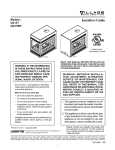
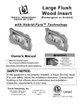
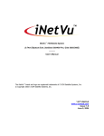
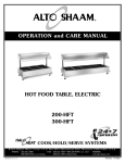
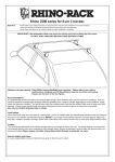
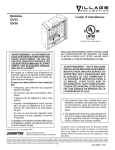
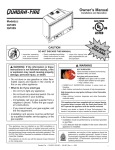
Models:
PIER-TVFL
ST-42TVFL
Installers Guide
Underwriters
Laboratories Listed
WARNING: IF THE INFORMATION
IN THESE INSTRUCTIONS IS NOT
FOLLOWED EXACTLY, A FIRE OR
EXPLOSION MAY RESULT CAUSING PROPERTY DAMAGE, PERSONAL INJURY, OR DEATH.
- Do not store or use gasoline or other flammable vapors and liquids in the vicinity of this
or any other appliance.
- What to do if you smell gas
• Do not try to light any appliance.
• Do not touch any electrical switch.
READ THIS MANUAL BEFORE INSTALLING OR
OPERATING THIS APPLIANCE. THIS INSTALLERS
GUIDE MUST BE LEFT WITH THE APPLIANCE
FOR FUTURE REFERENCE.
WARNING: IMPROPER INSTALLATION, ADJUSTMENT, ALTERATION,
SERVICE OR MAINTENANCE CAN
CAUSE INJURY OR PROPERTY DAMAGE. REFER TO THIS MANUAL. FOR
ASSISTANCE OR ADDITIONAL INFORMATION CONSULT A QUALIFIED INSTALLER, SERVICE AGENCY, OR THE
GAS SUPPLIER.
• Do not use any phone in your building.
• Immediately call your gas supplier from a
neighbor's phone. Follow the gas supplier's instructions.
• If you cannot reach your gas supplier, call the
fire department.
- Installation and service must be performed by a
qualified installer, service agency, or the gas
supplier.
Please contact your Heat-N-Glo dealer with any
questions or concerns. For the number of your nearest
Heat-N-Glo dealer, please call 1-888-427-3973.
Printed in U.S.A. Copyright 2004,
Heat-N-Glo, a brand of Hearth & Home Technologies Inc.
20802 Kensington Boulevard, Lakeville, MN 55044
This product is covered by one or more of the following patents: (United States) 4,112,913; 4,408,594; 4,422,426; 4,424,792; 4,520,791; 4,793,322;
4,852,548; 4,875,464; 5,000,162; 5,016,609; 5,076,254 5,191,877; 5,218,953; 5,328,356; 5,429,495; 5,452,708; 5,542,407; 5,613,487; (Australia) 543790;
1
586383; (Canada) 1,123,296; 1,297,746; 2,195,264; (Mexico) 97-0457; (New Zealand) 200265; or other U.S. and foreign patents pending.
455-900G 2/04
SAFETY AND WARNING INFORMATION
!
READ and UNDERSTAND all instructions carefully before starting the installation.
FAILURE TO FOLLOW these installation instructions may result in a possible fire
hazard and will void the warranty.
!
Prior to the first firing of the fireplace, READ the Using Your Fireplace section of the
Owners Guide.
!
DO NOT USE this appliance if any part has been under water. Immediately CALL a
qualified service technician to inspect the unit and to replace any part of the control
system and any gas control which has been underwater.
!
THIS UNIT IS NOT FOR USE WITH SOLID FUEL.
!
2
Installation and repair should be PERFORMED by a qualified service person. The
appliance and venting system should be INSPECTED before initial use and at least
annually by a professional service person. More frequent cleaning may be required due
to excessive lint from carpeting, bedding material, etc. It is IMPERATIVE that the unit’s
control compartment, burners, and circulating air passageways BE KEPT CLEAN to
provide for adequate combustion and ventilation air.
!
Always KEEP the appliance clear and free from combustible materials, gasoline, and
other flammable vapors and liquids.
!
NEVER OBSTRUCT the flow of combustion and ventilation air. Keep the front of the
appliance CLEAR of all obstacles and materials for servicing and proper operations.
!
Due to the high temperature, the appliance should be LOCATED out of traffic areas
and away from furniture and draperies. Clothing or flammable material SHOULD NOT
BE PLACED on or near the appliance.
!
Children and adults should be ALERTED to the hazards of high surface temperature
and should STAY AWAY to avoid burns or clothing ignition. Young children should be
CAREFULLY SUPERVISED when they are in the same room as the appliance.
!
These units MUST use one of the vent systems described in the Installing the Fireplace
section of the Installers Guide. NO OTHER vent systems or components MAY BE USED.
!
This gas fireplace and vent assembly MUST be vented directly to the outside and
MUST NEVER be attached to a chimney serving a separate solid fuel burning
appliance. Each gas appliance MUST USE a separate vent system. Common vent
systems are PROHIBITED.
!
INSPECT the external vent cap on a regular basis to make sure that no debris is
interfering with the air flow.
!
The glass door assembly MUST be in place and sealed, and the trim door assembly
MUST be in place on the fireplace before the unit can be placed into safe operation.
!
DO NOT OPERATE this appliance with the glass door removed, cracked, or broken.
Replacement of the glass door should be performed by a licensed or qualified service
person. DO NOT strike or slam the glass door.
!
The glass door assembly SHALL ONLY be replaced as a complete unit, as supplied
by the gas fireplace manufacturer. NO SUBSTITUTE material may be used.
!
DO NOT USE abrasive cleaners on the glass door assembly. DO NOT ATTEMPT to
clean the glass door when it is hot.
!
Turn off the gas before servicing this appliance. It is recommended that a qualified
service technician perform an appliance check-up at the beginning of each heating
season.
!
Any safety screen or guard removed for servicing must be replaced before operating
this appliance.
!
DO NOT place furniture or any other combustible household objects within 36 inches
of the fireplace front.
Safety and Warning Information ....................2
u Service
Parts List ...............................................4
Section 1: Approvals and Codes ................ 10
Appliance Certification .......................................... 10
Installation Codes ................................................. 10
u High Altitude Installations ...................................... 10
Table of
Contents
Section 2: Getting Started .............................11
Introducing the Heat-N-Glo Gas Fireplaces ......... 11
Pre-installation Preparation .................................. 11
Section 3: Installing the Fireplace .............. 14
Step 1
Step 2
Step 3
Locating the Fireplace ............................ 14
Framing the Fireplace ............................ 15
Negative Pressure Make-up Air .............. 16
Step 4
Installing the Vent System ...................... 18
A. Vent System Approvals ...................... 18
u B. System Components ......................... 18
C. Bedroom Installation in Canada ........ 20
D. Vent Termination ................................ 20
Step 5 Positioning, Leveling, and
Securing the Fireplace ........................... 21
Step 6 The Gas Control Systems ..................... 21
u Step 7 The Gas Supply Line .............................. 22
Step 8 Gas Pressure Requirements ................. 23
Step 9 Wiring the Fireplace ............................... 24
Step 10 Finishing ................................................. 25
Step 11 Installing Trim, Logs & Ember Material .. 27
Installing the Trim ................................... 27
Positioning the Logs ............................... 27
Placing the Ember Material .................... 28
Step 12 Before Lighting the Fireplace ................. 29
Step 13 Lighting the Fireplace ............................. 29
After the Installation .............................................. 29
Section 4: Maintaining and Servicing
Your Fireplace ............................. 30
u = Contains updated information.
3
PIER-TVFL, PIER-TVFL-DSI
Service Parts
(NG, LP) Exploded Parts Diagram
(GN, PL) Vue éclatée des pièces
MANUFACTURING DATES
SP Beginning: 8-97, Ending Date: ___
DSI Beginning: 8-97, Ending Date: 3-00
u
8
6
2
1
4
5
9
3
7 Log Assembly
* Part number list on following page.
* La liste des numéros de pièce se trouve
à la page suivante.
4
(NG, LP) Service Parts List / Liste des pièces de rechange
PIER-TVFL and PIER-TVFL-DSI
IMPORTANT: THIS IS DATED INFORMATION. The most current information is located on your dealers VIP site. When ordering, supply serial and model numbers to ensure correct service parts. / IMPORTANT : L'information fournie dans cette brochure
n'est valide que pendant une courte période. Les sites VIP des distributeurs disposent des renseignements les plus récents.
Lors d'une commande, veuillez fournir les numéros de série et de modèles pour un remplacement adéquat des pièces.
u
ITEM /
PIÈCE
STANDING PILOT AND DSI IGNITION COMMON PARTS
/ UNE VEILLEUSE ET ALLUMAGE DSI PIÉCES COMMUNES
1
End Glass Assembly / verre
2
Glass Door Assembly / Porte en verre
3
3
Burner NG / Brûleur GN
Burner LP / Brûleur PL
SERIAL #
/ N° DE SÉRIE
PART NUMBER
/ N° DE PIÈCE
GLA-PTRC-E
PRE 2-13-98
POST 2-13-98
GLA-PTRC
GLA-PIER
PRE 2824
501-176A
2824 TO 3003
501-173A
POST 3004
501-272A
PRE 1157
501-175A
1157 TO 1175
501-172A
POST 1176
501-273A
4
Surround Side / Entourer le Côté
502-202
5
Base Refractory (Fiber) / Réfractaire Base
SRV504-738-UM
5
Base Refractory (Metal) / Réfractaire Base
464-292
6
Refractory, Rear (Fiber) / Réfractaire
SRV504-737-UM
6
Refractory, Rear (Metal) / Réfractaire
464-280
7
Log Set Assembly (sold as complete log set only) / Jeu de Bûches
LOGS-MS
8
Hood / Hotte
455-322
9
Decorative Door / Porte décorative
DF-356H
STANDING PILOT IGNITION ONLY / ALLUMAGE UNE VEILLEUSE SEULEMENT
Pilot Orifice NG / Orifice de veilleuse GN
446-505
Pilot Orifice LP / Orifice de veilleuse PL
446-517
Pilot Tube / Tube de veilleuse
SRV485-301
Thermocouple / Thermocouple
446-511
Thermopile / Thermopile
060-512
Junction Box / Boîtier de dérivation
100-250A
ACCESSORIES / ACCESSOIRES
Remote Control Kit / Commande à distance
RC-SMART-HNG
Remote Control Kit / Commande à distance
SMART-STAT-HNG
Conversion Kit NG / Module de conversion GN
Conversion Kit LP / Module de conversion PL
PRE 3003
NGK-PTVFLB
POST 3004
PRE 1175
NGK-PTVFLMS
NGK-PTVFLMS-DSI
LPK-PTVFLB
POST 1176
LPK-PTRCMS
LPK-PTVFLMS-DSI
Also see additional pages for DSI and Standing Pilot service part numbers.
5
ST-42TVFL, ST-42TVFL-DSI
Service Parts
(NG, LP) Exploded Parts Diagram
(GN, PL) Vue éclatée des pièces
MANUFACTURING DATES
SP Beginning: 8-97, Ending Date: ___
DSI Beginning: 8-97, Ending Date: 8-02
u
1
3
5
1
5
7
4
2
6 Log Assembly
* Part number list on following page.
* La liste des numéros de pièce se trouve
à la page suivante.
6
(NG, LP) Service Parts List / Liste des pièces de rechange
ST-42TVFL and ST-42TVFL-DSI
IMPORTANT: THIS IS DATED INFORMATION. The most current information is located on your dealers VIP site. When ordering, supply serial and model numbers to ensure correct service parts. / IMPORTANT : L'information fournie dans cette brochure
n'est valide que pendant une courte période. Les sites VIP des distributeurs disposent des renseignements les plus récents.
Lors d'une commande, veuillez fournir les numéros de série et de modèles pour un remplacement adéquat des pièces.
u
ITEM /
PIÈCE
1
2
2
STANDING PILOT AND DSI IGNITION COMMON PARTS
/ UNE VEILLEUSE ET ALLUMAGE DSI PIÉCES COMMUNES
Glass Door Assembly / Porte en verre
Burner NG / Brûleur GN
Burner LP / Brûleur PL
SERIAL #
/ N° DE SÉRIE
PART NUMBER
/ N° DE PIÈCE
PRE 2-13-98
POST 2-13-98
GLA-PTRC
GLA-PIER
PRE 5292
501-176A
5292 TO 5997
501-173A
POST 5998
501-272A
PRE 1439
501-175A
1439 TO 1517
501-172A
POST 1518
501-273A
3
Hood / Hotte
455-322
4
Base Refractory (Fiber) / Réfractaire Base
SRV504-738-UM
4
Base Refractory (Metal) / Réfractaire Base
464-292
5
Refractory, Rear (Fiber) / Réfractaire
SRV504-737-UM
5
Refractory, Rear (Metal) / Réfractaire
464-280
6
Log Set Assembly (sold as complete log set only) / Jeu de Bûches
LOGS-MS
7
Decorative Door / Porte décorative
DF-36H
STANDING PILOT IGNITION ONLY / ALLUMAGE UNE VEILLEUSE SEULEMENT
Pilot Orifice NG / Orifice de veilleuse GN
446-505
Pilot Orifice LP / Orifice de veilleuse PL
446-517
Pilot Tube / Tube de veilleuse
SRV485-301
Thermocouple / Thermocouple
446-511
Thermopile / Thermopile
060-512
Junction Box / Boîtier de dérivation
100-250A
ACCESSORIES / ACCESSOIRES
Remote Control Kit / Commande à distance
RC-SMART-HNG
Remote Control Kit / Commande à distance
SMART-STAT-HNG
PRE 5997
Conversion Kit NG / Module de conversion GN
POST 5998
PRE 1517
Conversion Kit LP / Module de conversion PL
POST 1518
NGK-PTVFLB
NGK-PTVFLMS
NGK-PTVFLMS-DSI
LPK-PTVFLB
LPK-PTRCMS
LPK-PTVFLMS-DSI
7
Also see additional pages for DSI and Standing Pilot service part numbers.
7
PIER-TVFL, ST-42TVFL
Service Parts
(NG, LP) Exploded Parts Diagram
(GN, PL) Vue éclatée des pièces
Beginning Manufacturing Date: 10-97
Ending Manufacturing Date: ______
u
Standing Pilot Ignition
Valve Assembly
12
4
13
10
9
5
7
1
11
2
8
3
u
ITEM /
PIÈCE
6
DESCRIPTION
SERIAL #
/ N° DE SÉRIE
PART NUMBER
/ N° DE PIÈCE
1
Valve NG / Valve GN
060-522
1
Valve LP / Valve PL
060-523
2
ON/OFF Rocker Switch / Interrupteur à bascule MARCHE/ARRÊT
060-521A
3
Piezo Ignitor / Allumeur piézo
418-513
4
Pilot Assembly NG / Module de veilleuse GN
485-510A
4
Pilot Assembly LP / Module de veilleuse PL
485-511A
5
Valve Bracket / Parenthèse de Valve
501-115
6
Wire Assembly Piggyback / Le Ferroutage d'Assemblée de fil
049-552A
7
Flex Ball Valve Assembly / Fléchir l'Assemblée de Soupape de Balle
302-320A
8
Burner Tube / Tube de brûleur
501-302
9
High Temp Limit Switch / Interrupteur de détection thermique
066-531
10
Drop-In Plate / Tombe-dans Plaque
501-151
11
Valve Bracket Plate / La Plaque de Crochet de soupape
501-215
12
Burner Assembly / Brûleur
See previous pages
for part numbers
13
80" Wire Assembly / Module de fil
522-501A
Orifice NG (#33B) / Orifice GN (#33B)
455-800
Orifice LP (#48B) / Orifice PL (#48B)
042-800
8
Service Parts
PIER-TVFL-DSI, ST-42TVFL-DSI
(NG, LP) Exploded Parts Diagram
(GN, PL) Vue éclatée des pièces
u
MANUFACTURING DATES
ST-42TVFL-DSI Beginning: 8-97, Ending Date: 8-02
PIER-TVFL-DSI Beginning: 8-97, Ending Date: 3-00
9
Direct Spark Ignition
Valve Assembly
8
4
12
7
5
10
11
3
6
1
2
u
ITEM /
PIÈCE
DESCRIPTION
SERIAL #
/ N° DE SÉRIE
PART NUMBER
/ N° DE PIÈCE
1
Junction Box / Boîtier de dérivation
100-254A
2
ON/OFF Rocker Switch / Interrupteur à bascule MARCHE/ARRÊT
060-511
3
Burner Tube / Tube de brûleur
501-302
4
Orifice Assembly NG (#31B) / Assemblée d'Orifice GN (#31B)
455-800
4
Orifice Assembly LP (#48B) / Assemblée d'Orifice PL (#48B)
042-800
5
Valve Bracket / Parenthèse de Valve
501-115
6
Valve NG / Valve GN
492-500
6
Valve LP / Valve PL
492-501
7
Flex Ball Valve Assembly / Fléchir l'Assemblée de Soupape de Balle
302-320A
8
High Temp Limit Switch / Interrupteur de détection thermique
066-531
9
Burner Assembly NG / Brûleur GN
See previous pages
for part numbers
10
Drop-In Plate / Tombe-dans Plaque
501-151
11
Valve Support Bracket / Le Crochet de Soutien de soupape
501-215
12
Module / Module
501-592
Ignitor / Allumeur
501-591
9
1
Approvals
and Codes
Approval Listings
and Codes
Appliance Certification
The Heat-N-Glo fireplace models discussed in this
Installers Guide have been tested to certification
standards and listed by the applicable laboratories.
MODEL
LABORATORY
TYPE
Pier-TVFL
ST-42TVFL
Underwriters
Laboratories
B- Vent
Decorative
CERTIFICATION
STANDARD
ANSI Z21.50•CGA2.22
Installation Codes
The fireplace installation must conform to local codes. Before installing the
fireplace, consult the local building code agency to ensure that you are in
compliance with all applicable codes, including permits and inspections.
In the absence of local codes, the fireplace installation must conform to the
National Fuel Gas Code ANSI Z223.1 (in the United States) or the CAN/CGAB149 Installation Codes (in Canada). The appliance must be electrically
grounded in accordance with local codes or, in the absence of local codes with
the National Electric Code ANSI/NFPA No. 70 (in the United States), or to the
CSA C22.1 Canadian Electric Code (in Canada).
This model (natural gas and propane) can be installed in a bedroom (in the United
States) which has a total volume of unconfined space appropriate to the particular
installation. Refer to the National Fuel Gas Code ANSI Z223.1/NFPA54 (current
edition). The Uniform Mechanical Code - (current edition), and local Building
Officials for the options allowed in obtaining an effective bedroom volume of
unconfined space.
This model (natural gas and propane) can be installed in a bedroom (in Canada)
if a thermostat (Model WH-STAT) is installed with the unit. Consult local code
authorities. Detailed installation instructions for Model WH-STAT are included
with the kit.
High Altitude Installations
u U.L. Listed gas appliances are tested and approved without requiring changes for
elevations from 0 to 2,000 feet in the U. S. A. and in Canada.
When installing this appliance at an elevation above 2,000 feet, it may be necessary
to decrease the input rating by changing the existing burner orifice to a smaller
size. Input rate should be reduced by 4% for each 1000 feet above a 2000 foot
elevation in the U.S.A. or 10% for elevations between 2000 and 4500 feet in Canada.
If the heating value of the gas has been reduced, these rules do not apply. To
identify the proper orifice size, check with the local gas utility.
If installing this appliance at an elevation above 4,500 feet (in Canada), check with
local authorities.
Consult your local gas utility for assistance in determining the proper orifice for
your location.
10
Heat-N-Glo Quality
Systems registered
by SGS ICS
Introducing the
Heat-N-Glo
Gas Fireplaces
Heat-N-Glo B-type vent gas fireplaces are designed to
operate with all exhaust gases expelled to the outside
of the building.
The information contained in this Installers Guide,
unless noted otherwise, applies to all models and gas
control systems.
Gas fireplace diagrams, including the dimensions, are
shown in this section.
Pre-installation
Preparation
This gas fireplace and its components are tested and
safe when installed in accordance with this Installers
Guide. Report to your dealer any parts damaged in
shipment, particularly the condition of the glass. Do
not install any unit with damaged, incomplete, or
substitute parts.
2
Getting
Started
The vent system components are shipped in separate
packages. The gas logs are packed separately and
must be field installed. Read all of the instructions
before starting the installation. Follow these
instructions carefully during the installation to
ensure maximum safety and benefit. Failure to
follow these instructions will void the owner’s
warranty and may present a fire hazard.
The Heat-N-Glo Warranty will be voided by, and HeatN-Glo disclaims any responsibility for, the following
actions:
• Installation of any damaged fireplace or vent system
component.
• Modification of the fireplace or vent system.
• Installation other than as instructed by Heat-N-Glo.
• Improper positioning of the gas logs or the glass
door.
• Installation and/or use of any component part not
manufactured and approved by Heat-N-Glo not
withstanding any independent testing laboratory or
other party approval of such component part or
accessory.
ANY SUCH ACTION MAY POSSIBLY CAUSE A
FIRE HAZARD.
11
When planning a fireplace installation, it’s necessary to determine:
• Where the unit is to be installed.
• The vent system configuration to be used.
• Gas supply piping.
• Electrical wiring.
• Framing and finishing details.
• Whether optional accessories—devices such as a fan, wall switch, or remote
control—are desired.
If the fireplace is to be installed on carpeting or tile, or on any combustible
material other than wood flooring, the fireplace should be installed on a metal or
wood panel that extends the full width and depth of the fireplace.
21 5/8
(551mm)
24 1/4
(616mm)
12 1/8
(308mm)
VENT COLLAR
ELECTRICAL
ACCESS
GAS LINE
ACCESS
41
(1043mm)
36 7/8
(937mm)
24 1/4
(616mm)
36 7/8 (937mm)
40 3/4 (1035mm)
LEFT SIDE
TOP STANDOFFS
RATING PLATES
& LABELS
12
GAS LINE
ACCESS
Figure 1. Diagram of the Pier-TVFL
GAS CONTROL
VALVE
4
(102mm)
4
(102mm)
FRONT
1/2"
STANDOFFS
ELECTRICAL
ACCESS
2 1/2
(64mm)
2 1/2
(64mm)
RIGHT SIDE
21 5/8
(549mm)
24 1/4
(616mm)
12 1/8
(308mm)
VENT
COLLAR
ELECTRICAL
ACCESS
GAS LINE
ACCESS
41
(1042mm)
36 7/8
(937mm)
2 1/2
(64mm)
2 1/2
(64mm)
36 1/8 (918mm)
4 (102mm)
43 (1093mm)
4
(102mm)
LEFT SIDE
FRONT
RIGHT SIDE
TOP STANDOFFS
ELECTRICAL
ACCESS
1/2" STANDOFFS
RATING PLATE
& LABELS
GAS LINE
ACCESS
GAS
CONTROL VALVE
Figure 2. Diagram of the ST-42TVFL
13
Step 1
Locating the
Fireplace
3
The diagram below shows space and clearance
requirements for locating a fireplace within a room.
GLASS
GLASS
36"
GLASS
PIER-TVFL
Installing the
Fireplace
36 "
TOP
VIEW
36"
ST-42TVFL
GLASS
1"
GLASS
Figure 3.
Fireplace Locations and Space
Requirements
Clearance Requirements
The top, back, and sides of the fireplace are defined
by stand-offs.
Minimum Clearances from the Fireplace to
Combustible Materials
Glass
Sides
36 inches
(914 mm)
Floor
0
Back of
Fireplace
Metal Ends
of Fireplace
Top of
Fireplace
Ceiling*
1/2 inch
(13 mm)
1/2 inch
(13 mm)
4-1/2 inches
(89 mm)
31 inches
(787 mm)
* The clearance to the ceiling is measured from the top of
the unit, excluding any standoffs (see Figure 13).
The minimum clearance to a perpendicular wall extending
past the face of the fireplace is one inch (25 mm).
The metal end(s) of these fireplaces may NOT be
recessed into combustible construction.
14
Minimum Clearances from the B-Type Vent Pipe
to Combustible Materials is 1 inch (25 mm) all
around the pipe.
Step 2
Framing the
Fireplace
Fireplace framing can be built before or after the
fireplace is set in place. Framing should be
positioned to accommodate wall coverings and
fireplace facing material. The diagram below shows
framing reference dimensions.
CAUTION
MEASURE FIREPLACE DIMENSIONS, AND
VERIFY FRAMING METHODS AND WALL
COVERING DETAILS, BEFORE FRAMING
CONSTRUCTION BEGINS.
PIER-TVFL
ST-42TVFL
FRAMING
HEADERS
C
C
B
A
A
B
MODEL
PIER
ST-42TVFL
A
40 1/4
44
B
23 1/4
23 1/4
C
41 1/2
41 1/2
Figure 5. Framing Dimensions
15
Step 3
Negative
Pressure
Make-up Air
Negative Pressure warning: When negative pressure
is present, an atmospherically vented fireplace (with a
draft hood) may not function properly and it may down
draft. In the case of a gas appliance, spillage of the
combustion gases may occur. This may create a
dangerous carbon monoxide situation in the house.
The causes of negative pressure to a house can include
the following:
• Stack effect in the building.
• Exhaust only appliances (mechanically and
atmospherically vented).
• Inadequate make-up air (which is increasingly
more prevalent in new construction).
NOTE: This fireplace will operate correctly only if
adequate ventilation is provided to allow proper draft to
the fireplace system. Heat-N-Glo assumes no
responsibility for the improper performance of the
fireplace system caused by inadequate draft due to
environmental conditions, down drafts, tight sealing
construction of the structure, or mechanical exhausting
devices which create a negative air pressure within the
structure where the fireplace is located.
It is recommended that all natural venting non-air tight
gas fireplaces have outside air connected to them. It is
also recommended that the building be mechanically or
passively balanced to allow atmospherically vented
appliances, such as top vented gas fireplaces with draft
hoods, to draft properly. If the home experiences
negative pressure or is likely to experience negative
pressure, connection to an outside air source is
mandatory.
Installing Optional Outside Make-up Air: This unit is
equipped to accept outside air. By using outside makeup air, the amount of room air used for combustion will
be reduced. It is recommended that an AK-TV air kit be
used with this appliance.
!
WARNING: IN A NEGATIVE PRESSURE
CONDITION (LIKELY TO OCCUR IN NEW
HOMES THAT DO NOT HAVE ADEQUATE
MAKE-UP AIR) THE OUTSIDE AIR KIT
MUST BE INSTALLED TO OBTAIN
PROPER PERFORMANCE AND TO HELP
PREVENT SPILLAGE OF COMBUSTION
GASES.
A 4-inch damper assembly (found in AK-TV Kit) must be
installed to the fireplace. See Figure 5. Attach the
damper assembly to the outer wrap of the fireplace using
sheetmetal screws
16
Detailed installation instructions for Model AK-TV
Outside Air kit are found in the kit.
Air Damper
Before lighting the burner, open the damper plate by
sliding the air damper rod, located by the gas valve,
towards you.
DUCT COLLAR
DAMPER
ASSEMBLY
Figure 5. Make-up Air
17
Step 4
Installing the
Vent System
A. Vent System Approvals
These fireplaces are approved to use 6-inch (152mm)
diameter B-type vent. B-type vent must be used
when the vent system is within combustible
construction.
These models may also use single wall rigid or flexible
gas vent IF and ONLY IF the vent system is installed
within non-combustible construction such as a masonry
chimney. The same diameters noted above for B-type
vent must be used for single-wall vent. See Figure 6.
The flame and ember appearance may vary based on
the type of fuel burned and the venting configuration used.
B. System Components.
Vent System Configuration
MAXIMUM TOTAL HORIZONTAL RUN = 17 FT.
MINIMUM TOTAL VERTICAL RISE = 10 FT.
MAXIMUM NO. of ELBOWS: 2 - 90o or 4 - 45o
Plan and install the vent system using the parameters
shown above.
!
WARNING: YOU MUST NOT EXCEED
THESE PARAMETERS.
Connect a B-Type vent component to the flue outlet
collar. Look at top inside of the firebox to check that
the vent pipe is attached to the unit. NOTE: It is
required to first attach a straight section of vent
to the unit before attaching a 90 o elbow. Avoid
using elbows in the vent system if possible.
A 90-degree elbow CANNOT be attached directly to u
the unit. A 45o elbow can be attached directly to
the unit. It must have a straight section of pipe
attached to it for a MINIMUM of 4-feet before a
second 450 elbow to a horizontal run (see Figure 6).
The horizontal component of the vent system must
not exceed a MAXIMUM of 17-feet. The vertical
component of the vent system must exceed a
MINIMUM of 10-feet. Two 450 elbows to vertical can
be used at any length within the 17-feet maximum
horizontal component.
Continue to add vent components, until the vent run is
completed.
!
WARNING: YOU MUST NOT EXCEED A
TOTAL MAXIMUM HORIZONTAL RUN OF
17 FEET FOR THE ENTIRE VENT SYSTEM.
NOTE: The vent termination must be in a vertical
position and the termination cap must be listed
for the vent pipe used.
18
Consult local building code officials and codes for
proper vent system installations.
4 FT.
MINIMUM
MAXIMUM HORIZONTAL RUN
17 FT.
MAXIMUM
10 FT.
MINIMUM
4 FT
MINIMUM
Figure 6. Vent System Attachment
!
WARNING: THIS GAS FIREPLACE
MUST NEVER BE VENTED BY
CONNECTING TO A CHIMNEY FLUE
SERVING A SEPARATE SOLID FUEL
BURNING APPLIANCE.
19
C. Bedroom Installation in Canada
This model MUST NOT be vented into a vent
system installed exterior to a building. The part of
the vent system above the roof line can be exterior
to the building.
D. Vent Termination
!
WARNING: MAJOR U.S. BUILDING
CODES SPECIFY MINIMUM
CHIMNEY AND/OR VENT HEIGHT
ABOVE THE ROOF TOP. THESE
MINIMUM HEIGHTS ARE
NECESSARY IN THE INTEREST OF
SAFETY. FIGURE 7 AND TABLE
SHOW MINIMUM HEIGHTS,
PROVIDED THE TERMINATION CAP
IS AT LEAST 8-FEET FROM A
VERTICAL WALL.
NOTE: THERE SHOULD BE A 5 FOOT (60”)
MINIMUM CLEARANCE T O AN UNVENTILATED
VINYL CLAD SOFFIT.
VENT CAP
LOWEST DISCHARGE OPENING
X
12
ROOF PITCH IS X/12
H (MIN.)-MINIMUM HEIGHT FROM ROOF
TO LOWEST DISCHARGE OPENING
ROOF PITCH
H (MIN.) FT.
FLAT TO 6/12
6/12 TO 7/12
OVER 7/12 TO 8/12
OVER 8/12 TO 9/12
OVER 9/12 TO 10/12
OVER 10/12 TO 11/12
OVER 11/12 TO 12/12
OVER 12/12 TO 14/12
OVER 14/12 TO 16/12
OVER 16/12 TO 18/12
OVER 18/12 TO 20/12
OVER 20/12 TO 21/12
1.0
1.25
1.5
2.0
2.5
3.25
4.0
5.0
6.0
7.0
7.5
8.0
Figure 7. Vent Termination
20
Step 5
Positioning,
Leveling, and
Securing the
Fireplace
The diagram below shows how to properly position,
level, and secure the fireplace.
1. Place the fireplace
into position.
2. Level the fireplace
from side to side and
from front to back.
3. Shim the fireplace
with non-combustible
material, such as
sheet metal, as
necessary.
4. Secure the fireplace to
the framing by nailing
or screwing.
NAILING TABS
AT BASE OF
FIREPLACE.
Figure 8. Proper Positioning, Leveling, and
Securing of a Fireplace
Step 6
The Gas Control
Systems
WARNING: THIS UNIT IS NOT FOR USE
WITH SOLID FUEL.
!
Direct Spark Ignition (DSI) or Standing Pilot (Millivolt)
gas control systems are used in these models.
Standing Pilot Ignition System
This system includes millivolt control valve, standing
pilot, thermopile/thermocouple flame sensor, and
piezo ignitor.
!
WARNING
110-120 VAC MUST NEVER BE
CONNECTED TO A CONTROL VALVE IN
A MILLIVOLT SYSTEM.
Direct Spark Ignition (DSI) System
This system includes a 110V control valve, electronic
module (with internal transformer) and spark ignitor/
flame sensor.
!
WARNING: CONTINUOUS 110 -120 VAC
SERVICE MUST BE DIRECTLY WIRED
TO THE FIREPLACE JUNCTION BOX IN
A DSI SYSTEM.
21
STANDING PILOT
DSI IGNITION
Figure 9. Gas Controls Systems
Step 7
The Gas
Supply Line
NOTE: Have the gas supply line installed in
accordance with local building codes by a qualified
installer approved and/or licensed as required
by the locality. (In the Commonwealth of u
Massachusetts installation must be performed by
a licensed plumber or gas fitter).
NOTE: Before the first firing of the fireplace, the
gas supply line should be purged of any trapped air.
NOTE: Consult local building codes to properly
size the gas supply line leading to the 1/2 inch
(13 mm) hook-up at the unit.
This gas fireplace is designed to accept a 1/2 inch
(13 mm) gas supply line. To install the gas supply line:
• A listed (and Commonwealth of Massachusetts ap- u
proved) 1/2 inch (13mm) tee-handle manual shutoff valve and a listed flexible gas connector are
connected to the 1/2 inch (13mm) inlet of the control valve. NOTE: If substituting for these components, please consult local codes for compliance.
• The gas line may be run from either side of the
fireplace provided the hole in the outer wrap does
not exceed 2 inches in diameter and it does not
penetrate the airtight firebox.
• The gap between the supply piping and gas access hole can be plugged with non-combustible
insulation to prevent cold air infiltration.
• Locate the gas line access hole in the outer casing of
the fireplace.
• Remove decorative door by lifting up away to gain
access to the gas control and shut-off valve, insert
the gas supply line through the gas line hole, and connect it to the shut-off valve.
• When attaching the pipe, support the control so that
the lines are not bent or torn.
• After the gas line installation is complete, all connec- u
tions must be tightened and checked for leaks with a
commercially available, non-corrosive leak check solution. Be sure to rinse off all leak check solution following testing.
22
!
WARNING: DO NOT USE AN OPEN FLAME TO
CHECK FOR GAS LEAKS.
• At the gas line access hole, use insulation to repack the space around the gas pipe.
• Insert insulation from the outside of the fireplace and
pack the insulation tightly to totally seal between the
pipe and the outer casing.
The gas line should be
installed by a qualified
service technician.
USE A WRENCH ON
SHUT-OFF VALVE
WHEN TIGHTENING
GAS LINE
MANUAL
SHUT-OFF
VALVE
GAS VALVE
GAS LINE
ACCESS
FLEX
CONNECTOR
Figure 10. Gas Supply Line
Step 8
Gas Pressure
Requirements
Pressure requirements for Heat-N-Glo gas fireplaces
are shown in the table below.
Pressure
Natural Gas
Propane
Minimum
Inlet Pressure
5.0 inches
w.c.
11.0 inches
w.c.
Maximum Inlet
Gas Pressure
14.0 inches
w.c.
14.0 inches
w.c.
Manifold
Pressure
3.5 inches
w.c.
10.0 inches
w.c.
A one-eighth (1/8) inch (3 mm) N.P.T. plugged tapping
is provided on the inlet and outlet side of the gas
control for a test gauge connection to measure the
manifold pressure.
The fireplace and its individual shut-off valve must be
disconnected from the gas supply piping system
during any pressure testing of the system at test
pressures in excess of one-half (1/2) psig (3.5 kPa).
The fireplace must be isolated from the gas supply
piping system by closing its individual shut-off valve
during any pressure testing of the gas supply piping
system at test pressures equal to or less than one-half
(1/2) psig (3.5 kPa).
23
Step 9
Wiring the
Fireplace
NOTE: Electrical wiring must be installed by a
licensed electrician.
Caution: Disconnect remote controls if you are
absent for extended time periods. This will
prevent accidental fireplace operation.
For Standing Pilot Ignition Wiring
Appliance Requirements
• This appliance DOES NOT require 110-120 VAC to
operate.
!
WARNING
DO NOT CONNECT 110-120 VAC TO THE
GAS CONTROL VALVE WALL SWITCH
OR THE APPLIANCE WILL
MALFUNCTION AND THE VALVE WILL
BE DESTROYED.
Optional Accessories
Optional remote control kits require that 110-120 VAC
be wired to the factory installed junction box before the
fireplace is permanently installed.
Wall Switch
Position the wall switch in the desired position on a
wall. Run a maximum of 25 feet (7.8 m) or less length
of 18 A.W.G. minimum wire and connect it to the
fireplace ON/OFF switch pigtails.
!
CAUTION
WARNING
DO NOT CONNECT 110-120 VAC TO THE
WALL SWITCH OR THE CONTROL
VALVE WILL BE DESTROYED.
LABEL ALL WIRES PRIOR TO DISCONNECTION
WHEN SERVICING CONTROLS. WIRING
ERRORS CAN CAUSE IMPROPER AND
DANGEROUS OPERATION. VERIFY PROPER
OPERATION AFTER SERVICING.
BLACK L2
BLACK L1
HI-TEMP LIMIT SWITCH
REMOTE SWITCH
PIGTAIL
GAS VALVE
ON
OFF
WHITE T2
ON/OFF SWITCH
RED T1
THERMOPILE
THERMOCOUPLE
24
BLACK S1
Figure 11. Standing Pilot Ignition Wiring Diagram
OPTIONAL WALL SWITCH,
THERMOSTAT OR REMOTE
OPTIONAL REMOTE,
HI TEMP
L2
WALL SWITCH
LIMIT SWITCH
OR THERMOSTAT
(NEUTRAL)
(ON CERTIFIED UNITS ONLY)
100-254A
OPTIONAL
JUNCTION L1
FAN
(HOT)
BOX
SWITCHES
120 VAC
476-500
DSI CONTROL VALVE
459-591
IGNITOR
WHITE
ON/OFF
REM FAN
BLUE
GROUND
ORANGE
BLACK
501-592
DSI
MODULE
WHITE
YELLOW
GROUND
TO
FIREPLACE
CHASSIS
GREEN
BLUE
WHITE
BLACK
FLAME SENSOR/SPARKER
HI-TEMP
LIMIT SWITCH
IGNITION
MODULE
ON/OFF SWITCH
GAS
VALVE
REMOTE OUTLET
FAN OUTLET
NEUTRAL
CONNECTORS
HOT
GROUND
Figure 12. Direct Spark Ignition (DSI) Wiring Diagram
For Direct Spark Ignition (DSI) Wiring
Appliance Requirements
This appliance requires that 110-120 VAC be wired
to the factory installed junction box. Maintain correct
polarity when wiring the junction box.
Optional Accessories
Optional remote control kits require that 110-120
VAC be wired to the fireplace junction box.
Wall Switch
Position the wall switch in the desired position on a
wall. Run a maximum of 25 feet (7.8 m) or less of
16 A.W.G. minimum wire and connect it to the
fireplace ON/OFF switch pigtails.
CAUTION
LABEL ALL WIRES PRIOR TO
DISCONNECTION WHEN SERVICING
CONTROLS. WIRING ERRORS CAN CAUSE
IMPROPER AND DANGEROUS OPERATION.
VERIFY PROPER OPERATION AFTER
SERVICING.
25
Step 10
Finishing
The following diagram shows the minimum vertical
and corresponding maximum horizontal
dimensions of fireplace mantels or other
combustible projections above the top front edge
of the fireplace. See Figures 3 and 4 for other
fireplace clearances.
Only noncombustible
materials may be
used to cover the
black fireplace front.
CEILING
DRY WALL
31”
12"
TOP FRONT
EDGE OF
FIREPLACE
1 1/2"
MINIMUM
Figure 13. Minimum Vertical and Maximum
Horizontal Dimensions of
Combustibles above Fireplace
!
CAUTION
26
WARNING
WHEN FINISHING THE FIREPLACE,
NEVER OBSTRUCT OR MODIFY THE
AIR INLET/OUTLET GRILLES IN ANY
MANNER.
IF JOINTS BETWEEN THE FINISHED WALLS AND
THE FIREPLACE SURROUND (TOP AND SIDES)
ARE SEALED, A 300° F. MINIMUM SEALANT MATERIAL MUST BE USED. THESE JOINTS ARE
NOT REQUIRED TO BE SEALED. ONLY NONCOMBUSTIBLE MATERIAL (USING 300° F. MINIMUM ADHESIVE, IF NEEDED) CAN BE APPLIED
AS FACING TO THE FIREPLACE SURROUND.
SEE THE FOLLOWING DIAGRAM
ST-42TVFL
1. Apply only noncombustible facing
material to the
fireplace surround.
TOP EDGE
1/2"
SIDE EDGE
1/2" GAP
BOTH ENDS
TOP EDGE
1/2"
SIDE EDGE
1/2" GAP
PIER-TVFL
Figure 14. Sealant Material
Hearth Extensions
A hearth extension may be desirable for aesthetic
reasons. However, ANSI or CAN/CGA testing
standards do not require hearth extensions for gas
fireplace appliances.
Step 11
Installing Trim,
Logs, and Ember
Material
Installing the Trim
Combustible materials may be brought up to the
specified clearances on the side and top front edges
of the fireplace, but MUST NEVER overlap onto the
front face. The joints between the finished wall and
the fireplace top and sides can only be sealed with a
300° F. (149° C) minimum sealant.
!
WARNING: WHEN FINISHING THE
FIREPLACE, NEVER OBSTRUCT OR
MODIFY THE AIR INLET/OUTLET
GRILLES IN ANY MANNER.
Install optional marble and brass trim surround kits as
desired. Marble, brass, brick, tile, or other noncombustible materials can be used to cover up the
gap between the sheet rock and the fireplace.
Do not obstruct or modify the air inlet/outlet grilles.
When overlapping on both sides, leave enough space
so that the glass door can be removed.
Positioning the Logs
If the gas logs have been factory installed they should
not need to be positioned.
If the logs have been packaged separately, refer to
the installation instructions that accompany the logs.
Save the log instructions with this manual.
If sooting occurs, the logs might need to be repositioned
slightly to avoid excessive flame impingement.
27
GLASS SPECIFICATIONS:
LARGE GLASS:
TEMPERED
SMALL GLASS:
TEMPERED
Heat-N-Glo fireplaces manufactured with tempered
glass may be installed in hazardous locations such as
bathtub enclosures as defined by the CPSC. The tempered glass has been tested and certified to the requirements of ANSI Z97.1-1984 and CPSC 16 CFR 1202.
(Safety Glazing Certification Council SGCC # 1595 and
1597. Architectural Testing, Inc. Reports 02-31919.01
and 02-31917.01.)
This statement is in compliance with CPSC 16 CFR
Section 1201.5 “Certification and labeling requirements”
which refers to 15 USC 2063 stating “…Such certificate shall accompany the product or shall otherwise be
furnished to any distributor or retailer to whom the product is delivered.”
Some local building codes require the use of tempered
glass with permanent marking in such locations. Glass
meeting this requirement is available from the factory.
Please contact your dealer or distributor to order.
Placing the Ember Material
Ember material is shipped with this gas fireplace. The bag
labeled Golden Ember (GE-93) is flame colorant material.
The bag labeled Glowing Ember (050-721) is standard
glowing ember material. To place the ember material:
• Remove the wing nuts and glass clips or tension springs
around the glass door. Remove the glass door from the unit.
• Save the remaining
ember materials for
use during fireplace servicing. The bag of embers provided is sufficient for 3 to 5 applications.
• Place dime size pieces of ember material about 1/2
inch apart near port holes in burner top. Do NOT press
embers into burner ports. Cover the top of the burner
with a single layer of ember material. For best performance do NOT place embers on the ports at the rear of
the burner.
• Replace the wing nut,
glass clips and screws.
• Replace the glass door
and a front trim door on
the unit.
• Hand tighten the wing
nut.
28
Figure 15. Placement of the Ember Material
Step 12
Before Lighting
the Fireplace
Before lighting the fireplace, be sure to do the
following:
Remove all paperwork and documents from
underneath the fireplace.
Review safety warnings and cautions
• Read the Safety and Warning Information
section at the beginning of this Installers Guide.
Double-check for gas leaks
• Before lighting the fireplace, double-check the unit
for possible gas leaks.
Double-check vent terminations and front
grilles for obstructions.
• Before lighting the fireplace, double-check the unit
for possible obstructions that could be blocking the
vent terminations or the front grilles.
Double-check for faulty components
• Any component that is found to be faulty MUST
BE replaced with an approved component. Tampering with the fireplace components is DANGEROUS and voids all warranties.
A small amount of air will be in the gas supply lines.
When first lighting the fireplace, it will take a few
minutes for the lines to purge themselves of this air.
Once the purging is complete, the fireplace will light
and will operate normally.
Subsequent lightings of the fireplace will not require
this purging of air from the gas supply lines, unless
the gas valve has been turned to the OFF position,
in which case the air would have to be purged.
NOTE: The fireplace should be run 3 to 4 hours on the
initial start-up. Turn it off and let it cool completely.
Remove and clean the glass. Replace the glass and
run the fireplace for an additional 8 hours. This will help
to cure the products used in the paint and logs.
Step 13
Lighting the
Fireplace
You’ve reviewed all safety warnings, you’ve checked
the fireplace for gas leaks, you know the vent system
is unobstructed, and you’ve checked for faulty
components. Now you’re ready to light the fireplace.
!
After the
Installation
WARNING: PLEASE REFER TO THE USER’S MANUAL FOR ALL CAUTIONS,
SAFETY, AND WARNING INFORMATION
PERTAINING TO THE LIGHTING AND OPERATION OF THE FIREPLACE.
LEAVE THIS INSTALLATION MANUAL WITH
THE APPLIANCE FOR FUTURE REFERENCE.
29
4
Maintaining
and
Servicing
Your
Fireplace
30
Fireplace
Maintenance
Although the frequency of your fireplace servicing
and maintenance will depend on use and the type of
installation, you should have a qualified service
technician perform an appliance check-up at the
beginning of each heating season. See the table
below for specific guidelines regarding each
fireplace maintenance task.
IMPORTANT
TURN OFF THE GAS BEFORE SERVICING
YOUR FIREPLACE.
Type of
Fireplace
Maintenance
Frequency
By
Fireplace Maintenance Task To
Be Completed
Replacing
Old Ember
Material
Once annually,
during the
annual check-up
Qualified
Service
Technician
Brush away loose ember material near
the burner. Replace old ember
material with new dime-size and -shape
pieces of Golden Ember (GE-93) and
Glowing Ember (050-721). New ember
material should be placed alternately on
top of the burner—a layer of Golden
Ember, a layer of Glowing Ember,
and so on. Save the remaining ember
material and repeat this procedure at
your next servicing.
Cleaning
Burner
& Controls
Once annually
Qualified
Service
Technician
Brush or vacuum the control
compartment, fireplace logs, and
burner areas surrounding the logs.
Checking
Flame
Patterns,
Flame Height
Periodically
Qualified
Service
Technician/
Owner
Make a visual check of your fireplace’s
flame patterns. Make sure the flames
are steady—not lifting or floating. See
the picture in Figure 16. The flame
sensor (DSI) or thermopile/ thermocouple
(Standing Pilot) tips should be covered
with flame. See the picture in Figure 17.
Checking
Vent System
Before initial use
and at least
annually thereafter,
more frequently
if possible
Qualified
Service
Technician/
Owner
Inspect the external vent cap on a
regular basis to ensure that no debris is
interfering with the flow of air. Inspect
entire vent system for proper function.
Cleaning
As necessary
Homeowner
Remove and clean glass after the first 3
to 4 hours of use. After the initial
cleaning, clean as necessary,
particularly after adding new ember
(flame colorant) material. Film deposits
on the inside of the glass door should
be cleaned off using a household glass
cleaner. NOTE: DO NOT handle or
attempt to clean the door when it is hot
and DO NOT use abrasive cleaners.
MAKE SURE THE FLAMES
ARE STEADY—NOT
LIFTING OR FLOATING.
Figure 16. Burner Flame Patterns
STANDING PILOT
3/8"
(10mm)
DSI IGNITION
NOTE: FLAMES
TOO CLOSE TO
THE CERAMIC
INSULATORS CAN
CAUSE NUISANCE
LOCKOUTS AND
ELECTRODE
FAILURE.
IGNITOR
3/8"
(10mm)
CERAMIC
INSULATOR
3/32"
Figure 17. Ignitor Flame Patterns
31