1
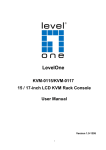
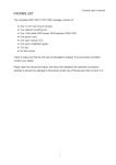
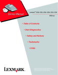
OPERATING INSTRUCTIONS
M-1264
M-1212E
STEREO MIXERS
TOA 1000 series
THE
LIGHTNING
FLASH
WITH
ARROWHEAD WITHIN A TRIANGLE IS
INTENDED TO TELL THE USER THAT
PARTS INSIDE THE PRODUCT ARE A
CAUTION
TO REDUCE THE RISK OF ELECTRICAL
SHOCK,
DO
NOT
REMOVE
COVER.
RISK
OF
ELECTRIC
SHOCK
TO
PERSONS.
NO USER SERVICEABLE PARTS INSIDE.
THE
REFER
SERVICING
TRIANGLE IS INTENDED TO TELL THE
SERVICE
PERSONNEL
TO
QUALIFIED
USER
EXCLAMATION POINT
THAT
WITHIN A
IMPORTANT OPERATING
AND
SERVICING INSTRUCTIONS
ARE
IN
THE
THE
PAPERS
WITH
APPLIANCE.
Please follow the instructions in this manual to obtain the optimum results from this unit.
We also recommend you to keep this manual handy for future reference.
TOA Corporation
CONTENTS
Handling Precautions
General Description
Features
Nomenclature (Front Panel)
Nomenclature (Rear Panel)
Input Transformer Mounting
Phantom Power Supply
Input and Output Specifications
Block Diagrams and Level Diagrams
Specifications
Accessories
Appearance
HANDLING PRECAUTIONS
Operating voltage is 120V AC ± 10% (120 V version) or 220-240V AC ± 10% (220-240 V version).
Avoid using the power voltage exceeding these ranges.
Do not expose the unit to corrosive chemicals or salt water. Also, keep your beverages away from the unit
because they may be spilt.
When there is a failure, refer the unit to qualified service personnel.
Observe the following polarity of the XLR connector:
Pin #1: Ground, Pin #2: Cold, Pin #3: Hot
GENERAL DESCRIPTION
The TOA M-1264 is a 19" rack-mountable stereo mixer with multiple inputs and outputs. Inputs can be expanded by
using the M-1212E expansion unit.
FEATURES
Six monaural inputs (expandable using the M-1212E), four stereo inputs and one auxiliary stereo input.
One each of output: stereo, group (L/R), stereo sum, monitor (L/R), AUX, and headphone.
A compressor built in each monaural input minimizes signal distortion caused when there is an extremely large
input. The activation of the compressor can be indicated by a compressor activation lamp.
Motorized stereo/group output volume controls can be remotely adjusted from a control device. The adjusted
control position is indicated on the control device.
The M-1212E can function as a sub-mixer because it has mixing outputs (stereo L/R, group L/R, AUX, and cue).
Phantom power (+24V DC) can be supplied to each monaural input.
A channel switch with an "easy-to-see" indicator provided for each input improves the signal-to-noise ratio and
simplifies operations.
4-step stereo/group send selection switch (stereo to group/group to stereo bus/group to post-stereo output
control/ OFF).
A 3-step input level selection switch (LINE/MIC/MIC (HPF)) allows selection of either a line or microphone
level input for each monaural input. The MIC (HPF) position cuts undesired frequencies using a highpass filter.
Electronically-balanced monaural input can be changed to a transformer-balanced input using an optional input
transformer.
Security cover.
NOMENCLATURE [Front Panel]
[M-1264] (Main unit)
[M-1212E] (Expansion unit)
L/C/R assign switch [L/C/R]
Bus assign switch [ASSIGN]
Aux assign switch [AUX]
Cue switch [CUE]
Input level control
Channel switch/indicator
Stereo output level control [STEREO]
Adjusts the level to send out a mixed input signal from the stereo bus to the stereo output. This control can be
remotely operated.
Group output level control [GROUP]
Adjusts the level to send out a mixed input signal from the group bus to the group output. This control can be
remotely operated.
Sum output level control [SUM]
Adjusts the stereo sum output signal level.
Aux output level control [AUX]
Adjusts the level of signals going to the AUX output.
Monitor output level control [MONITOR]
Adjusts the level to transmit a signal from the stereo bus or cue bus to the monitor output and headphone output.
Cue indicator [CUE]
Lights when any cue switch is pressed, indicating that the cue bus signal is being sent to both the monitor and
headphone outputs. If the indicator is off, the stereo bus signals are sent to both outputs.
Headphone jack [PHONES]
Outputs the signal adjusted with the monitor output level control. Connect a headphone with 8 ohms or higher
impedance.
Power indicator [POWER]
Power switch
Turns on the power when this switch is pressed (the power indicator lights). To turn off the power, press this
switch again (the indicator is extinguished).
L/C/R assign switches [L/C/R]
Assign each monaural input signal to L, R, or both L and R lines of the group or stereo bus selected with the bus
assign switch _ .
Bus assign switches [ASSIGN (ST/GR)]
Assign the monaural input signal adjusted with the input level control
to the stereo or group bus. (ON: group /
OFF: stereo)
Aux assign switches [AUX]
Send the input signal to the AUX bus.
Cue switches [CUE]
Send the input signal to the cue bus regardless of the position of the channel switch
signal at the headphone or monitor output.
, allowing monitoring of the
Input level controls
Adjust each input signal level.
Channel switches/indicators
Send the input signal to the bus selected with both the L/C/R assign switch _ and bus assign switch © or with
the AUX assign switch
. At the same time, the corresponding channel indicator lights green for monaural input
or yellow for stereo input. If the monaural channel indicator lights red, this indicates that the corresponding
compressor is activated. In such cases, adjust the input level using the input level control, as required. (The
compressor is activated when the signal level exceeds +17 dB.)
NOMENCLATURE [Rear Panel]
[M-1264] (Main unit)
[M-1212E] (Expansion unit)
Input level selection switches [LINE/MIC/MIC (HPF) ]
Set each monaural input level for Line, Mic or Mic with highpass filter.
Monaural input XLR connectors [MONO INPUT 1~6 (M-1264) /1~12 (M-1212E) ]
This electronically-balanced input can be changed to the transformer-balanced type using an optional input
transformer. (Refer to the section "Input Transformer Mounting" on page 8.) Phantom power (+24V DC) can also
be supplied to each input.
Stereo input RCA jacks [STEREO INPUT 1~4 L/MONO, R]
Unbalanced stereo input.
Auxiliary stereo input phone jacks [ST BUSS IN L/MONO, R]
Unbalanced stereo input to send signals to the stereo bus.
Bus-link input terminal [BUSS LINK IN]
Connects to the M-1212E's bus-link output for monaural input expansion. (For connection, use the cable supplied
with the M-1212E.)
Sum output XLR connector [SUM OUT]
Electronically-balanced stereo sum output.
AUX output phone jack [AUX OUT]
Unbalanced AUX output.
Monitor output phone jacks [MONITOR OUT L, R]
Unbalanced monitor output.
Stereo output XLR connectors [STEREO OUT L, R]
Electronically-balanced stereo output.
Stereo/group send selection switch
Four-step selection switch.
• STEREO TO GROUP position: Sends the stereo bus signal to the group bus.
• OFF
• GROUP TO STEREO(PRE) position: Sends the group output signal to the stereo bus.
• GROUP TO STEREO(POST) position: Sends the group output signal mixed with the stereo signal adjusted
with the stereo output level control to the stereo output.
Group output phone jacks [GROUP OUT L, R]
Unbalanced group output.
Remote terminals [REMOTE]
Used for remotely operating the stereo output level control and group output level control. There are four
following terminals:
UP : While this terminal and COM terminal are shorted, the level control rotates clockwise.
DOWN : While this terminal and COM terminal are shorted, the level control rotates counter-clockwise.
COM : Common terminal
POSI : The voltage of 0 to +5V DC is output between this terminal and COM terminal depending on the knob
setting (0-10).
Note : Do not leave the UP and DOWN terminals shorted for longer than necessary.
Fuse and fuse holder
When replacing, be sure to use the specified type and ratings of fuse to avoid the risk of fire. (1.5 A/250 V for
120V AC version, and T315 mA/250 V for 220-240V AC version)
AC power cord
Ground loop break switch
This switch, when set to "LIFT" position, breaks a hum-generating ground loop formed when the unit is connected
to external components. Normally, set this switch to "NORM" position.
Bus-link output terminal [BUSS LINK OUT]
Connects to the M-1264's bus-link input terminal.
Bus-link input terminal [BUSS LINK IN]
Connects to other M-1212E's bus-link output terminal for monaural channel expansion. (For connection, use the
cable supplied with the M-1212E.)
Stereo mixing output phone jacks [STEREO MIX OUT L, R]
Unbalanced stereo bus mixing output.
Group mixing output phone jacks [GROUP MIX OUT L, R]
Unbalanced group bus mixing output.
AUX mixing output phone jack [AUX MIX OUT]
Unbalanced AUX bus mixing output.
Cue mixing output phone jack [CUE MIX OUT]
Unbalanced cue bus mixing output.
INPUT TRANSFORMER MOUNTING
CAUTION
THESE SERVICING INSTRUCTIONS ARE FOR USE BY QUALIFIED PERSONNEL ONLY. TO AVOID ELECTRIC
SHOCK, DO NOT PERFORM ANY SERVICING OTHER THAN THAT CONTAINED IN THE OPERATING
INSTRUCTIONS UNLESS YOU ARE QUALIFIED TO DO SO. REFER ALL SERVICING TO QUALIFIED SERVICE
PERSONNEL
The M-1264's (M-1212E's) monaural inputs are electronically balanced.
They can be made transformer-balanced inputs using the optional input transformer LT-101 or LT-102.
How to mount the input transformer
Set the power switch to OFF and remove the power cord from a wall outlet.
Remove the unit's case by loosening six side panel screws (three each on both sides) and two rear panel
screws.
Fix two sleeves to the bottom chassis using screws, then mount the transformer to the sleeves using other
screws. (The sleeves and screws are supplied with the transformer.) When stacking two transformers due to the
number or arrangement of channels, use the sleeves supplied with the M-1264 (M-1212E).
When changing the inputs 1, 3, 5, etc. located in the upper section, detach connector
from CN-104 connector,
connect the detached connector to the transformer connector
, and connect the transformer lead
to the
CN-104. When changing the inputs 2, 4, 6, etc. in the lower section, detach connector
from CN-105 connector,
connect the detached connector to the transformer connector
, and connect the transformer lead
to the
CN-105.
Replace the case.
MONO INPUT
CH-1 (CH-2)
[Note] *1: For the upper inputs.
*2: For the lower inputs.
Sleeves supplied with
the M-1264 (M-1212E)
Bottom chassis
Sleeves supplied
with the optional
transformer
Top view
Side view
Matching Transformer Specifications
Model
Impedance
10k
Frequency response
* 0 dB = 0.775 Vrms
:10k
600
: 600
Within ± 0.15 dB (30 Hz~20 kHz)
Within ± 0.15 dB (30 Hz~20 kHz)
Within 1.5 dB (1 kHz)
Within 1.5 dB (1 kHz)
0.2 % or less (50 Hz / +5 dB*)
0.2 % or less (50 Hz / +5 dB*)
Constant loss
Distortion
LT-102
LT-101
** Specifications are subject to change without notice.
PHANTOM POWER SUPPLY
CAUTION
THESE SERVICING INSTRUCTIONS ARE FOR USE BY QUALIFIED PERSONNEL ONLY. TO AVOID ELECTRIC
SHOCK, DO NOT PERFORM ANY SERVICING OTHER THAN THAT CONTAINED IN THE OPERATING
INSTRUCTIONS UNLESS YOU ARE QUALIFIED TO DO SO. REFER ALL SERVICING TO QUALIFIED SERVICE
PERSONNEL.
Phantom power (+24V DC) can be supplied to each monaural input using the internal phantom power switch.
Set the power switch to OFF, and remove the power cord from a wall outlet.
Remove the unit's case by loosening six side panel screws (three each on both sides) and two rear panel screws.
Set the phantom power switch of the desired input to ON.
Replace the case.
[Precautions]:
To avoid electric shocks, do not touch the unit's internal components except when installing the input transformer
and setting the phantom power switch.
Leave the phantom power switch in the OFF position for inputs not receiving the phantom power. (The unit is
factory-preset as shown in the figure below.)
Upper switch
Lower switch
Upper inputs (CH-1, 3, 5, ..)
Lower inputs (CH-2, 4, 6, ..)
M-1264 (M-1212E) rear panel
INPUT AND OUTOUT SPECIFICATIONS
Input/Output
Level
Impedance
Connector
Line
-10 dB
50 k
Mic
-60 dB
1k
Mic (with HPF)
-60 dB
1k
-10 dB
50 k
RCA jack
Auxiliary Stereo Input (L, R)
+4 dB
10 k
Unbalanced phone jack
Stereo Output (L, R)
+4 dB
Monaural Input
Stereo Input (L, R)
600
XLR 3-pin connector
or more
(Matched load)
XLR 3-pin connector
600
or more
Sum Output
+4 dB
Group Output (L, R)
+4 dB
1k
Monitor Output (L, R)
+4 dB
1k
AUX Output
+4 dB
1k
Stereo Mixing
+4 dB
1k
Mixing Output
Group Mixing
+4 dB
1k
(M-1212E)
AUX Mixing
+4 dB
1k
Cue Mixing
+4 dB
1k
(Matched load)
Unbalanced phone jack
Unbalanced phone jack
BLOCK DIAGRAM AND LEVEL DIAGRAM
[M-1212E]
SPECIFICATIONS
Frequency
Response
20Hz~20kHz(+0,-1.5dB)
Total Harmonic
Distortion
Noise Level
(IHF- A)
M-1212E
M-1264
Model
0.15 % or less (Monaural Input to Stereo Output +4 dB*, 1 kHz)
0.01 % or less (Stereo Input to Stereo Output, +4 dB*, 1 kHz)
(1)When all volume controls are in
minimum position.
Stereo Output : - 100 dB or less
(2) When the stereo volume control is in
maximum position and all other controls
in minimum position.
Stereo Output :
—98 dB or less (Only M-1264 used)
(1) When all volume controls are in minimum
position.
Stereo Mixing Output : -94 dB or less
(2) When one monaural input level control is
in maximum position and all other
controls in minimum position.
Stereo Mixing Output : -62 dB or less
—92 dB or less (Both M-1264 and
M-1212E used)
(3) When the stereo volume control and one
monaural input level control are in
maximum position, and all other controls
in minimum position.
Stereo Output : -62 dB or less
Maximum voltage
gain
Monaural input (Mic) to stereo output : 64 dB
Monaural input (Line) to stereo output : 14 dB
Stereo input to stereo output : 14 dB
Compressor
(monaural input)
Activation signal level : +17 dB or more
Compression ratio : 10:1 (Compression curve : Soft knee)
Power
consumption
Dimensions
25 W (120V AC version)
26 W (1 20V AC version)
28 W (220-240V AC version)
28 W (220-240V AC version)
482.6 (W) x 88.4 (H) x 311.8 (D) mm (18.82" x 3.45" x 12.16")
Weight
5.2kg (11.47lb.)
0 dB = 0.775 Vrms.
Specifications are subject to change without notice.
ACCESSORIES
[M-1264]
Security cover x 1
Security cover fixing screw x 2
Fuse (250 V, 1.5 A) (for 120V AC version) x 1
Fuse (250 V, T315 mA) (for 220-240V AC version) x 1
Rack mounting screw x 4
Transformer mounting sleeve x 6
Warranty card (for USA and Canada) x 1
Operating instructions x 1
[M-1212E]
Security cover x 1
Security cover fixing screw x 2
Fuse (250 V, 1.5 A) (for 120V AC version) x 1
Fuse (250 V, T315 mA) (for 220-240V AC version) x 1
Rack mounting screw x 4
Transformer mounting sleeve x 12
Bus-link cable (1 m) x 1
Warranty card (for USA and Canada) x 1
Operating instructions x 1
APPEARANCE
[M-1264]
[M-1212E]
TOA Corporation
Printed in Japan
133-12-150-2B