1
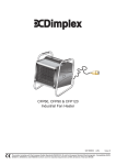
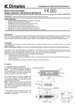
CFS30, CFS60, CFS90 & CFS120
Standard Wall Mounted Fan Heater
08/19437/1 (UK)
Issue 1
The product complies with the European Safety Standards EN60335-2-30 and the European Standard Electromagnetic Compatibility (EMC)
EN55014, EN60555-2 and EN60555-3 which cover the essential requirements of EEC Directives 73/23 and 89/336
2
1
D2
1000mm
100mm
Min.
D1
70mm
Min.
H
70mm
500mm
Min.
CFS30
CFS60
CFS90
CFS120
L
L
306
386
386
386
45o Max.
500mm
Min.
H
262
360
360
360
2.0m MIN
D1
495
565
565
565
D2
526
630
630
630
3b
3a
1 2
b
a
c
d
4
CFS60
CFS90
CFS120
5
CFS30
'y'
7
CFS30
2
1
3
y
x
230-240V ~1PN
a
CFS60
CFS90
CFS120
b
c
6
D
E
L
N
E
L1
M
d
E
C
F
H1 H2
T
1
10
0
145mm
2
3
I
8
85mm
120mm
9
T
SPC
380 - 415V
3PN + E
L2 L3
N L1
D
N
L
F
H1 H2
11
T
M
C
1L1 3L2 5L3 13NO A1
1L1 3L2 5L3 13NO A1
A
B
2T1 4T2 6T3 14NO A2
2T1 4T2 6T3 14NO A2
E
CFS60
CFS90
CFS120
12
220 - 240V ~1PN + E
PINK
PINK
BLUE
BLUE
BLUE
BLUE
VIOLET
VIOLET
BROWN
BROWN
ORANGE
ORANGE
WHITE
WHITE
BROWN
CFS60
CFS90
CFS120
220 - 240V ~3P + E
380 - 415V ~3PN + E
(FACTORY SUPPLIED)
N
L1
L2
L3
BROWN
BROWN
VIOLET
VIOLET
BROWN
BLUE
BLUE
BLUE
BLUE
WHITE
WHITE
PINK
PINK
ORANGE
ORANGE
N
L1
PINK
PINK
BLUE
BLUE
BLUE
BLUE
VIOLET
VIOLET
BROWN
BROWN
BROWN
N
L1
L2
WHITE
WHITE
L2
L3
ORANGE
ORANGE
L3
= CFS90 & CFS120
CFS60
CFS90
CFS120
Dimplex Industrial Fan Heater
Models : CFS30, CFS60, CFS90 & CFS120
THESE INSTRUCTIONS SHOULD BE READ CAREFULLY AND RETAINED FOR FUTURE REFERENCE
Wall Mounting
IMPORTANT SAFETY ADVICE
DO NOT COVER OR OBSTRUCT the air inlet or outlet grille.
ENSURE THE APPLIANCE IS EARTHED.
Always disconnect supply before working on the product.
Do not use this heater in areas where excessive dust exists.
This heater must not be located immediately above or below
a fixed socket outlet or connection box.
This product should be mounted safely to a solid wall.
Ensure the supply cables are of adequate current carrying
capacity and are protected by a suitable fuse.
This appliance should only be connected to the fixed wiring
of the premises by means of conduit.
This product must not be subjected to water spray or
immersion.
If the appliance is mounted in a toilet or washroom, the
appliance should be mounted such that no part of it can be
touched by a person using a fixed bath or shower.
If the appliance is mounted in a toilet or washroom an
isolating switch must be provided outside the washroom
adjacent to the entrance door.
The Switch Panel should not be installed in a toilet or
washroom.
CAUTION (CFS30 only) – In order to avoid a hazard due to
inadvertent resetting of the thermal cut-out, this appliance
MUST NOT be supplied through an external switching device,
such as a timer, or connected to a circuit that is regularly
switched on and off by the utility.
General
A range of robust, durable wall mounting fan heaters designed
to coordinate with the Dimplex range of Air Curtains, providing
environmental heating in commercial and light industrial
environments.
The heaters work by gradually raising the air temperature in the
building and should be positioned so as best to achieve an
even temperature distribution. The product range has outputs of
3kW, 6kW, 9kW and 12kW.
Model
Heat
Electrical
Electrical
Output
Supply
Load
Weight
Min
Installed
(per phase)
kW
CFS30
1.5 / 3
CFS60
3/6
CFS90
CFS120
6/9
6 / 12
height
A
kg
m
230-240V~ 1PN
12.7
7.6
2
220-240V~ 1PN
26.0
220-240V~ 3P
15.6
13.5
2
14.5
2
14.5
2
380-415V~ 3PN
9.0
220-240V~ 1PN
38.8
220-240V~ 3P
23.0
380-415V~ 3PN
13.3
220-240V~ 1PN
51.6
220-240V~ 3P
30.4
380-415V~ 3PN
17.5
Remove the wall mounting bracket from the back of the heater
and using it as a guide (see Fig. 2) mark off the hole positions on
a suitable wall (a minimum height of 2 meters is required from
the floor level to the bottom of the bracket). Solid brick or concrete
block walls must be drilled and plugged. Fix the wall mounting
bracket to the wall and assemble the heater to the extension
tube using a bolt and wing nut fitted into hole 1 shown in Fig. 3a.
Rotate the heater as shown in Fig. 3b, and fix the heater into
position using the remaining bolt and wing nut in hole 2. Pivot
and rotate the heater into the desired position and tighten all
three wing nuts. A 6mm Allen key can be used as an aid to
tightening the bolts.
Electrical and Control connections
Note: The installation of this appliance should be carried out
by a competent electrician and be in accordance with the
current IEE wiring regulations.
Electrical power and control connections for all CFS models are
made by removing the control housing and bottom Panel. The
control housing (‘y’ in Fig. 4 and Fig. 5) is detached by removing
the two screws and hinging the housing as shown (see step 1
in Fig. 5). The bottom panel (‘x’ in Fig. 5) is detached by removing
two screws and lifting off as shown (see steps 2 & 3 in Fig. 5).
Note : Removal of bottom panel is not required for CFS30.
Note: A suitable local isolating switch must be provided in the
electrical supply circuit as close as possible to the heater with at
least 3mm clearance on each pole.
CFS30
Remove knock-out from back panel of heater and feed
appropriate supply cable (see ‘a’ in Fig. 4) to terminal block ‘c’
(see Fig. 4). Make electrical connections as shown in Fig. 7 and
fix cable in back panel using suitable cable gland (not supplied).
By removing the other knock-out and using 5 core cable (see ‘b’
in Fig. 4) make the control connections to terminal block ‘d’ also
shown in Fig. 4.
CFS60, CFS90 & CFS120
Remove large knock-out from back panel of heater and feed
appropriate supply cable (see ‘a’ in Fig. 6) to terminal blocks ‘c’.
Make electrical connections as shown in Fig. 9 and fix cable in
back panel using suitable cable gland (not supplied). By removing
one of the smaller knock-outs and using 5 core cable (see ‘b’ in
Fig. 6) make the control connections to terminal block ‘d’ also
shown in Fig. 6.
Fix this cable in the back panel using suitable cable gland (not
supplied) and feed back to the switch panel using suitable
conduit. Refer to Switch Panel section for connections. Replace
the control housing and switch on power to heater. Ensure that
all switch settings are functioning correctly.
Note: The factory supplied unit can accept three phase voltage
of ~380-415V. For single phase ~220-240V and three phase
~220-240V refer to the electrical wiring label (see Fig. 12) fixed to
the underside of the bottom panel. To change between different
voltage systems, rearrange the push on connections as per the
required wiring diagram.
Wiring Diagrams
Recycling
CFS30 - see Fig. 7.
For electrical products sold within the
European Community.
CFS60, CFS90 & CFS120 - see Fig. 9.
At the end of the electrical products useful life it
should not be disposed of with household
waste. Please recycle where facilities exist.
Check with your Local Authority or retailer for
recycling advice in your country.
A - Heat 1 Contactor
B - Heat 2 Contactor
C - Cut-out circuit
D - Mains In Terminal Block
E - Elements
Cleaning
T - Control Terminal Block
WARNING: DISCONNECT SUPPLY before carrying out
maintenance.
M - Motor
External appearance can be maintained by wiping occasionally
with a damp cloth. For stain removal, a weak soap solution can
be applied with a cloth and the surface wiped dry. Care must be
taken to avoid any moisture ingress into the product.
Switch Panel
Installation
The backing box should be fixed to a suitable wall with
appropriate conduit used where applicable to carry the cable
between the heater and the switch panel. (see Fig. 8 for
dimensions)
This cable used to connect the heater to the switch panel should
have sufficient cores (typically 5 core) to allow connection as per
the enclosed wiring diagram and be at least 1.0mm².
Test all switch settings once installation is complete.
Switch Panel Connections
Connections are made as shown in Fig. 10. (References listed
below).
1
- FAN ON - OFF
2
- HEAT 1
3
- HEAT 2
T
- TERMINAL BLOCK
Your product is guaranteed for one year from the date of purchase.
Within this period, we undertake to repair or exchange this product
free of charge provided it has been installed and operated in
accordance with these instructions.
Your rights under this guarantee are additional to your statutory
rights, which in turn are not affected by this guarantee.
Should you require after sales service you should contact our
customer services help desk on 0870 727 0101. It would assist
us if you can quote the model number, series, date of purchase,
and nature of the fault at the time of your call. The customer
services help desk will also be able to advise you should you
need to purchase any spares.
Please do not return a faulty product to us in the first instance as
this may result in loss or damage and delay in providing you with
a satisfactory service.
SPC - SWITCH PANEL CABLE TO HEATER (NOT SUPPLIED)
Tip: When stripping back the switch panel cable make note of
the numbering or colours of each wire and their associated
connections to the terminal block.
Operation of switch panel
Switch on electrical supply (MAINS IN) to the heater. Switching
the switch marked ‘I’ energises the fan. The heat selection
switches allow heat settings to be chosen as shown below:
Settings -
After Sales Service
I
Fan Only
I+
Half Heat
I+
Full Heat
The desired heater setting can be obtained through switch
selection.
Thermal Safety Cut-out
The power supply to the heating elements will be interrupted if
one or a combination of the following abnormal events occurs:
1.
Air inlet or outlet grilles are obstructed.
2.
Internal ventilation is impaired due to build up of dust and
fluff.
3.
Blower unit stalls.
NOTE: Before re-setting the reason for activation must be
determined and corrective action taken.
To reset the thermal safety cut-out for the CFS60, CFS90 or
CFS120 models, access reset buttons as shown in Fig. 11 and
push in direction of arrow. The CFS30 has an electrical reset
cut-out which requires the power supply to be removed for a
short period of time to allow the cut-out cool down. On return of
the power supply, the heater should operate normally.
Please retain your receipt as proof of purchase.
Glen Dimplex UK Limited
Millbrook House
Grange Drive
Hedge End
Southampton
Hampshire. SO30 2DF
UK customer help line (8.00AM – 6.00PM Mon-Fri; 8.30AM-1.00PM Sat)
Customer Services:
Republic of Ireland
Tel.
Fax.
e-mail
Tel.
0870 7270101
0870 7270102
[email protected]
01 8424833
[c] Glen Dimplex UK Limited
All rights reserved. Material contained in this publication may not be reproduced in whole or in part, without prior permission in writing of Glen Dimplex UK Limited.