1
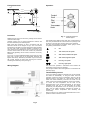
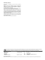
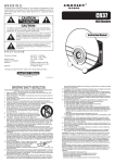
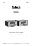
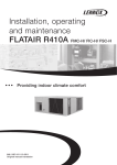
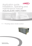
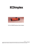
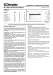
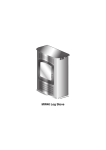
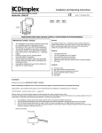
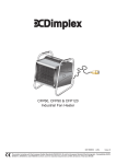
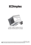
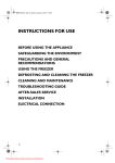
Installation and Operating Instructions
Dimplex Wall-mounted Fan Convector
08/18724/2
Issue 2
Models : WFC 3NB and WFC 3NS
575mm
Dimensions
Model(s)
Specification
WFC 3NB
3kW, Switch, Thermostat & Neon - Black
WFC 3NS
3kW, Switch, Thermostat & Neon - Silver
120mm
350mm
Fig. 1
350mm min
THESEINSTRUCTIONS
INSTRUCTIONSSHOULD
SHOULDBE
BEREAD
READCAREFULLY
CAREFULLYAND
ANDRETAINED
RETAINEDFOR
FORFUTURE
FUTUREREFERENCE
REFERENCE. .
THESE
Installation
IMPORTANT SAFETY ADVICE
WARNING – THIS APPLIANCE MUST NOT BE USED IN
A BATHROOM.
WARNING – DO NOT USE THIS HEATER IN THE
IMMEDIATE SURROUNDINGS OF A BATH, A SHOWER
OR A SWIMMING POOL.
WARNING – THIS HEATER MUST NOT BE LOCATED
IMMEDIATELY BELOW A FIXED SOCKET OUTLET.
DO NOT USE THE HEATER UNTIL IT IS WALL
MOUNTED CORRECTLY.
The heater carries a warning 'Do Not Cover' to alert
the user to the risk of overheating that exists if the
heater is accidentally covered.
NEVER cover or obstruct in any way the air inlet slots
at the front of the heater or the heat outlet slots in the
base of the heater.
Keep combustible materials such as drapes and other
furnishings clear from the front of the heater. Do not
use heater to dry your laundry.
This appliance is not intended for use by children or
other persons without assistance or supervision if
their physical, sensory or mental capabilities prevent
them from using it safely. Children should be
supervised to ensure that they do not play with the
appliance.
If young children, the aged, or infirm are likely to be
left in the vicinity of the heater, we advise that
adequate precautions should be taken. We
recommend that a guard be fitted to ensure contact
with the heater is avoided and objects cannot be
inserted into the product.
WARNING: In order to avoid a hazard due to
inadvertent resetting of the thermal cut-out, this
appliance must not be supplied through an external
switching device, such as a timer, or connected to a
circuit that is regularly switched on and off by the
utility.Do not use where excessive dust or moisture is
present.
For further information, please contact our guard
supplier direct on Tel. No. 01603 667957, or in the
case of difficulty or for further advice contact the
Customer Helpline.
Before undertaking installation work, ensure the electricity
supply is disconnected from any relevant fixed wiring.
Supply cable is not provided with this appliance, and a
competent electrician should therefore install it.
The appliance must be fitted horizontally with the cable or
conduit entry at bottom right. It should be mounted such that the
underside is at least 350mm above the floor and the top of the
heater is 150mm below any overhanging shelf or obstruction.
This heater must be used on an A.C.~ supply only and the
voltage marked on the heater must correspond to the
supply voltage.
To comply with the I.E.E. Wiring Regulations, the appliance
must be earthed; the supply circuit must be adequate for the
input of the appliance, and the circuit protected by a suitable
13A fuse. A suitable termination to the fixed wiring of the
premises must be provided adjacent to the final position of the
appliance. In this instance, such a termination can be a doublepole switch with a contact separation of at least 3mm in all
poles.
The heater must not be located immediately below a fixed
socket-outlet.
Electrical
WARNING : THIS APPLIANCE MUST BE EARTHED.
After ensuring the electricity supply is not live, electrical
connections can be made, either to an adjacent double-pole
switch having a contact separation of at least 3mm in all poles
or to a plug-top for use in a standard 13A socket.
If the latter: Connect Green and Yellow wire to plug terminal
marked E or
Green or Green and Yellow. Connect Blue
wire to plug terminal marked N or Black. Connect Brown wire
to plug terminal marked L or Red.
Refit cover, first hooking top over the back of the unit and then
securing the bottom by refitting the two screws under the
bottom edge. The appliance is now ready for use and the
electricity supply can be reinstated.
Fixing dimensions
Operation
shelf
150mm min
6mm
575mm
510mm
Ø10mm
8mm
350mm
280mm
cable or
conduit entry
35mm
350mm min.
Fig. 2
Procedure
Release the front cover from the unit by undoing the two screws
under the bottom edge.
Carefully remove cover by pulling bottom-front forward, and
then lift to release top from retaining slots.
Mark screw fixing positions on wall in accordance with the
dimensions shown on the diagram in Fig 2. The unit must be
secured to the wall with four screws through the holes provided.
The two upper holes are keyhole shaped to enable the two
upper screws to be positioned first. The unit can then be hung
on these screws while the two lower screws are positioned.
Before finally tightening all four screws, ensure the unit is truly
horizontal.
Fit a 3 core 1.5 square millimetre flexible cord through the cable
entry bush, connect wires to the appropriate terminals and
tighten cable clamp. Alternatively the heater may be connected
with conduit through the base after removing the knockout
containing the cable entry bush (see Fig. 2).
Wiring Diagram
Fig. 4 - Controls & Control
Panel Layout
The Dimplex WFC 3NB and WFC 3NS have a total loading of
3Kw. They are fitted with two control knobs and a pilot light. The
air inlet is in the front panel, and the outlet on the underside.
The upper knob operates a six-position switch, giving a choice
of operating characteristics as follows :
▬
Off
▬
1Kw of heat, low fan speed.
▬
2Kw of heat, medium fan speed.
▬
3Kw of heat, high fan speed.
▬
Fan only, low speed.
▬
Fan only, high speed.
The lower knob operates a thermostat which enables the
temperature of the room to be regulated.
The pilot light indicates when the appliance is connected to the
electricity supply.
Thermal Safety Cut-out
In the event that the appliance overheats, the cut-out switches
the heater off automatically. To bring the heater back into
operation, remove the cause of overheating, then turn Off the
electrical supply to the heater for a few minutes. When the
heater has cooled sufficiently reconnect and switch On the
heater. If the cut-out operates repeatedly, contact your supplier.
To control the room temperature, set the mark on the
thermostat knob to the required temperature on the visually
graduated scale (see Fig. 4). The thermostat will monitor
continuously the temperature of the air returning to the inlet
grille, and the heater element(s) selected will achieve or
maintain the chosen temperature level efficiently and
economically.
When running Fan only modes, rotate thermostat knob to ‘max.’
position to ensure continuous cool air
Fig. 3
General Cleaning
WARNING :
BEFORE UNDERTAKING ANY MAINTENANCE OR
CLEANING WORK ON THE APPLIANCE, IMMEDIATELY
DISCONNECT THE ELECTRICITY SUPPLY EITHER BY
SWITCHING OFF AT THE ADJACENT DOUBLE POLE
SWITCH OR BY REMOVING THE PLUG FROM THE
SOCKET.
The outside of the appliance should be wiped over with a soft
damp cloth and then dried. Do not use detergents or abrasives.
The filter should be cleaned by gently passing the soft brush
attachment of a vacuum cleaner over the front grille.
Filter
Retaining
Wires
Mesh
Filter
Service and Repair
THE INTERNAL CLEANING AND MAINTENANCE WORK
SHOULD ONLY BE UNDERTAKEN BY COMPETENT
PERSONS WITH EXPERIENCE OF REPAIRING DOMESTIC
ELECTRICAL APPLIANCES AND IN FULL KNOWLEDGE OF
THE POSSIBLE HAZARDS INVOLVED.
To ensure the appliance operates efficiently, the following
maintenance should be undertaken periodically. The cover
should be removed and refitted as detailed under ‘Procedure’.
•
Fan Blades : These should be cleaned by using the soft
brush attachment of a vacuum cleaner. Care should be
taken not to damage the blades.
•
Filter : The filter can be removed completely for cleaning,
but generally provided this is cleaned frequently as
detailed above, this should not be necessary. Where
removal of filter is required for cleaning, the filter retaining
wires can be removed, allowing the mesh and the filter to
be taken out (see Fig. 5).
•
General : With the cover removed, opportunity should be
taken to remove any accumulations of dust from within the
unit.
•
Bearings : Fan and motor bearings should be given one
or two (not more) drops of low viscosity oil (e.g. sewing
machine oil) approximately every 12 months.
Recycling
For electrical products sold within the European Community.
At the end of the electrical products useful life
it should not be disposed of with household
waste. Please recycle where facilities exist.
Check with your Local Authority or retailer for
recycling advice in your country.
Air Inlet
Grille
Fig. 5
After Sales Service
Your product is guaranteed for one year from the date of
purchase.
Within this period, we undertake to repair or exchange this
product free of charge (excluding element & subject to
availability) provided it has been installed and operated in
accordance with these instructions.
Your rights under this guarantee are additional to your statutory
rights, which in turn are not affected by this guarantee.
Should you require after sales service you should contact our
customer services help desk on 0845 600 5111. It would assist
us if you can quote the model number, series, date of purchase,
and nature of the fault at the time of your call. The customer
services help desk will also be able to advise you should you
need to purchase any spares.
Please do not return a faulty product to us in the first instance
as this may result in loss or damage and delay in providing you
with a satisfactory service.
Please retain your receipt as proof of purchase.
The product complies with the European Safety Standards EN60335-2-30 and the European Standard Electromagnetic Compatibility
(EMC) EN55014, EN60555-2 and EN60555-3 which cover the essential requirements of EEC Directives 73/23 and 89/336
Glen Dimplex UK Limited
Millbrook House
Grange Drive
Hedge End
Southampton
Hampshire. SO30 2DF
UK customer help line 8.00AM – 5.00PM Mon-Fri; 8.30AM-1.00PM Sat (Autumn-Winter only)
Customer Services:
Republic of Ireland
Tel.
Fax.
e-mail
Tel.
0845 600 5111
01489 773053
[email protected]
01 8424833
[c] Glen Dimplex UK Limited
All rights reserved. Material contained in this publication may not be reproduced in whole or in part, without prior permission in writing of Glen Dimplex UK Ltd.