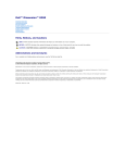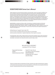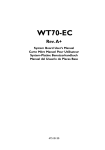
1
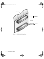
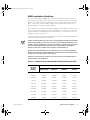
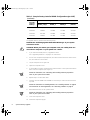
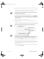
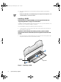
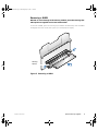
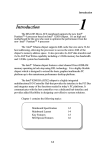
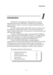
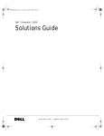
0E137a00.book Page 1 Thursday, May 3, 2001 1:36 PM
Dell Precision™ WorkStation 620
System Memory Upgrade
w w w. d e l l . c o m | s u p p o r t . d e l l . c o m
0E137a00.book Page 2 Thursday, May 3, 2001 1:36 PM
0E137a00.book Page 1 Thursday, May 3, 2001 1:36 PM
Dell Precision™ WorkStation 620
System Memory Upgrade
w w w. d e l l . c o m | s u p p o r t . d e l l . c o m
0E137a00.book Page 2 Thursday, May 3, 2001 1:36 PM
Notes, Notices, and Cautions
Throughout this guide, blocks of text may be accompanied by an icon and printed in
bold type or in italic type. These blocks are notes, notices, and cautions, and they are
used as follows:
NOTE: A NOTE indicates important information that helps you make better use of
your computer system.
NOTICE: A NOTICE indicates either potential damage to hardware or loss
of data and tells you how to avoid the problem.
CAUTION: A CAUTION indicates a potentially hazardous situation which, if
not avoided, may result in minor or moderate injury.
____________________
Information in this document is subject to change without notice.
© 2001 Dell Computer Corporation. All rights reserved.
Reproduction in any manner whatsoever without the written permission of Dell Computer
Corporation is strictly forbidden.
Trademarks used in this text: Dell, Dell Precision, and the DELL logo are trademarks of Dell
Computer Corporation.
Other trademarks and trade names may be used in this document to refer to either the entities
claiming the marks and names or their products. Dell Computer Corporation disclaims any
proprietary interest in trademarks and trade names other than its own.
May 2001
P/N 0E137 Rev. A00
0E137a00.book Page 1 Thursday, May 3, 2001 1:36 PM
Dell Precision™ WorkStation 620
System Memory Upgrade
This document provides instructions for upgrading the Rambus inline memory modules (RIMMs) on the Dell Precision WorkStation 620. Dell Precision 620 systems
support dual, direct, Rambus dynamic random-access memory (RDRAM) modules.
These RIMMs feature error checking and correction (ECC).
NOTES: Dell recommends that only a technically knowledgeable person perform this
procedure.
Dell recommends that you read the entire procedure before you begin. You must also
be familiar with removing the system cover and locating the RIMMs.
Dell recommends that you print the contents of the system User’s Guide for
referencing important information that may not be available during critical procedures.
This document is available on your Dell Precision ResourceCD and can also be
accessed from the User’s Guides icon on your current desktop if you have not
reinstalled the operating system.
Upgrading the BIOS
You must upgrade the basic input/output system (BIOS) before you upgrade the
RIMMs. Otherwise, the existing BIOS may not recognize the new RIMMs, and the
system will not operate.
To upgrade the BIOS:
1.
Download the BIOS update utility for the computer to be updated from the Dell
support website.
a.
Go to http://support.dell.com.
If this is your first time to use this website, complete the one-time
registration.
support.dell.com
b.
Click Downloads for Your Dell.
c.
Enter your Service Tag Number for the computer to be updated or select the
appropriate Dell™ system.
System Memory Upgrade
1
0E137a00.book Page 2 Thursday, May 3, 2001 1:36 PM
d.
Select the appropriate operating system (OS) and language for the computer
to be updated.
e.
Select FlashBIOS Updates for the download category.
f.
Click Go and follow the instructions on screen to create a diskette containing
the BIOS update files.
NOTE: For some Dell systems, you are given a choice to create a diskette containing the BIOS update files or to download a file you can use from the hard
drive. Select the choice to use the file that creates an installation diskette.
2.
Insert the BIOS update diskette into the diskette drive of the computer to be
updated. Then restart the computer.
The computer automatically updates the BIOS from the diskette.
3.
When the computer begins to restart and the Dell logo screen appears, remove
the diskette from the diskette drive so that the computer does not boot from the
diskette again.
Precautionary Measures
NOTICE: Before you upgrade the RIMMs, you must upgrade the BIOS. See
“Upgrading the BIOS” on page 1 for instructions.
Before you perform any of the procedures in this document, read the following notice
for your personal safety and to prevent damage to the system from electrostatic discharge (ESD).
NOTICE: The procedure in this document requires that you remove the
cover and work inside your computer. Do not attempt to service the computer except as explained in this document and elsewhere in Dell
documentation. Always follow installation and service instructions closely.
Before Removing the Cover
Before you remove the computer cover, perform the following steps in the sequence
indicated.
NOTICE: To help avoid possible damage to the system board, unplug your
computer system and wait 15 to 30 seconds before removing a component
from the system board or disconnecting a peripheral device from the
computer.
1.
Turn off the computer and any peripherals.
2.
Disconnect the computer and peripherals from their power sources. Also, disconnect any telephone or telecommunication lines from the computer.
Before disconnecting a peripheral from the computer or removing a component
from the system board, verify that the standby power light, located on the system board, has turned off. If it is on, you may need to wait 15 to 30 seconds for it
2
System Memory Upgrade
0E137a00.book Page 3 Thursday, May 3, 2001 1:36 PM
to go out (see the internal system board label that is attached to the cover of your
computer).
3.
Ground yourself by touching an unpainted metal surface on the chassis, such as
the metal around the card-slot openings at the back of the computer, before
touching anything inside your computer. Dell recommends that you use a wrist
grounding strap in this operation.
While you work, periodically touch an unpainted metal surface on the computer
chassis to dissipate any static electricity that might harm internal components.
Doing so reduces the potential for personal injury or shock.
In addition, take note of these safety guidelines when appropriate:
•
•
When you disconnect a cable, pull on its connector or on its strain-relief loop, not
on the cable itself. Some cables have a connector with locking tabs; if you are disconnecting this type of cable, press in on the locking tabs before disconnecting
the cable. As you pull connectors apart, keep them evenly aligned to avoid bending any connector pins. Also, before you connect a cable, make sure both
connectors are correctly oriented and aligned.
Handle components and cards with care. Do not touch the components or contacts on a card. Hold a card by its edges or by its metal mounting bracket. Hold a
component such as a RIMM by its edges, not by its pins.
Upgrading System Memory
NOTICE: Before you upgrade the RIMMs, you must upgrade the BIOS. See
“Upgrading the BIOS” on page 1 for instructions.
This computer has two memory expansion cards (MECs), both consisting of four
sockets: RIMM1_A, RIMM2_A, RIMM3_B, and RIMM4_B. On each MEC, sockets
RIMM1_A and RIMM2_A comprise channel A, and sockets RIMM3_B and RIMM4_B
comprise channel B.
Dell Precision 620 systems support a maximum of eight RIMMs (four RIMMs per
MEC) for up to 3 gigabytes (GB) of total memory.
NOTE: Although you can insert 512-megabyte (MB) RIMMs in each socket, the BIOS
revision only supports a maximum of 3 GB.
Figure 1 shows the RIMMs and RIMM sockets.
support.dell.com
System Memory Upgrade
3
0E137a00.book Page 4 Thursday, May 3, 2001 1:36 PM
MEC cover
RIMM1_A
RIMM2_A
channel A
riser board
RIMM3_B
RIMM4_B
Figure 1. RIMM Socket Designations
4
System Memory Upgrade
channel B
0E137a00.book Page 5 Thursday, May 3, 2001 1:36 PM
RIMM Installation Guidelines
You must install RIMMs in pairs. This means that the RIMM in each socket on one
MEC must be the same memory capacity, density, and speed as the corresponding
RIMM in the same socket on the other MEC. Also, for either channel A or B of each
MEC, if one socket contains a RIMM, then the other socket must contain either
another RIMM or a continuity RIMM (CRIMM).
As an example, if you install only one pair of RIMMs in the RIMM1_A socket of each
MEC, then you must install a CRIMM in socket RIMM2_A of each MEC. Channel B
(sockets RIMM3_B and RIMM4_B) may remain empty, or it may contain one or two
CRIMMs per MEC (see Figure 1).
However, if channel A contains two RIMMs and you want to install additional RIMMs,
the preceding rules also apply for channel B.
NOTES: If 512-MB RIMMs are used, they must be populated starting with the bottom
RIMM socket (RIMM4_B, the one closest to the system board) and working up. For
example, see the configuration in the last row in Table 1. In this example, you would
insert the 512-MB RIMMs into the bottom three sockets (RIMM4_B, RIMM3_B,
RIMM2_A) and insert a CRIMM into the topmost socket (RIMM1_A).
When you add 512-MB RIMMs from a customer kit, you must remove all existing
RIMMs and reinstall the new 512-MB RIMMs, beginning with socket RIMM4_B and
working up on each riser board in mirror fashion.
Dell does not recommend or support the mixing of old and new 512-MB RIMMs in
sockets RIMM1_A and RIMM2_A.
Table 1. Sample Factory-Installed RIMM Configurations (per MEC)
support.dell.com
Populate both MECs as follows:
For Total
Desired
Memory:
RIMM1_A (top)
RIMM2_A
RIMM3_B
RIMM4_B
(bottom)
128 MB
CRIMM
64 MB
Empty
Empty
256 MB
CRIMM
128 MB
Empty
Empty
384 MB
128 MB
64 MB
CRIMM
Empty
512 MB
128 MB
128 MB
CRIMM
Empty
512 MB
CRIMM
256 MB
Empty
Empty
768 MB
256 MB
128 MB
CRIMM
Empty
1024 MB
128 MB
128 MB
128 MB
128 MB
1024 MB
256 MB
256 MB
CRIMM
Empty
1536 MB
256 MB
256 MB
256 MB
CRIMM
2048 MB
256 MB
256 MB
256 MB
256 MB
System Memory Upgrade
5
0E137a00.book Page 6 Thursday, May 3, 2001 1:36 PM
Table 1. Sample Factory-Installed RIMM Configurations (per MEC)
(continued)
Populate both MECs as follows:
For Total
Desired
Memory:
RIMM1_A (top)
RIMM2_A
RIMM3_B
RIMM4_B
(bottom)
2048 MB
Empty
CRIMM
512 MB
512 MB
2560 MB
CRIMM
256 MB
512 MB
512 MB
3072 MB
256 MB
256 MB
512 MB
512 MB
3072 MB
CRIMM
512 MB
512 MB
512 MB
To upgrade memory, perform the following steps.
NOTICE: See “Protecting Against Electrostatic Discharge” in your System
Information Guide.
CAUTION: Before you remove your computer cover, see “Safety First—For
You and Your Computer” in your system User’s Guide.
1.
If you have not already done so, upgrade the BIOS.
See “Upgrading the BIOS” on page 1 for instructions.
2.
Turn off the computer and peripherals, disconnect them from their electrical outlets, and wait 10 to 20 seconds.
3.
Lay the computer on its right side.
4.
Open the computer cover.
5.
To lift the MEC from the system board, rotate the MEC cover up and remove the
MEC from the computer (see Figure 1).
NOTE: For instructions, see “Removing and Installing a Memory Expansion
Card” in your system User’s Guide.
6.
Repeat Step 5 for the other MEC.
7.
Install or remove RIMMs and CRIMMs as necessary to reach the desired memory total.
NOTE: For instructions on installing RIMMs, see “Installing a RIMM” on page 8.
For instructions on removing RIMMs, see “Removing a RIMM” on page 9.
8.
Reinstall both MECs on the system board.
NOTE: For instructions, see “Removing and Installing a Memory Expansion
Card” in your system User’s Guide.
9.
Close the computer cover.
10. Stand the computer upright.
6
System Memory Upgrade
0E137a00.book Page 7 Thursday, May 3, 2001 1:36 PM
11. Reconnect the computer and peripherals to their power sources, and turn them
on.
As the system boots, it detects the presence of the new RIMMs and automatically changes the system configuration information in system setup.
NOTES: Adding or removing RIMMs causes the following message to be displayed at the next system start-up:
The amount of system memory has changed.
After you replace the cover, if the chassis intrusion option is set to Enabled, the
chassis intrusion detector causes the following message to be displayed at the
next system start-up:
ALERT! Cover was previously removed.
12. Enter system setup. When Setup appears in the upper-right corner of the
screen, press <F2>.
If you wait too long and the operating system begins to load into memory, allow
the system to complete the load operation; shut down the system and try again.
NOTE: For instructions on using system setup, see the User’s Guide.
13. Reset the Chassis Intrusion option:
a.
Press the down-arrow key to move to the System Security option.
b.
Press <Enter> to access the System Security option's pop-up menu.
c.
Press the down-arrow key to move to the Chassis Intrusion option.
d.
Press the left- or right-arrow key to select Reset.
e.
Choose Enabled, Enabled-Silent, or Disabled.
NOTES: The chassis intrusion default is Enabled.
If a setup password has been assigned by someone else, contact the network
administrator for information on resetting the chassis intrusion detector.
See the system User's Guide for information on the chassis intrusion detector.
14. When the memory total is correct, press <Esc> to exit system setup.
If the memory total is incorrect, repeat steps 2 through 9. Check the installed
MECs and modules to ensure that they are seated properly in their sockets. Then
repeat steps 10 through 13.
If the memory total is still incorrect, contact Dell for technical support. See “Getting Help” in the User’s Guide.
support.dell.com
System Memory Upgrade
7
0E137a00.book Page 8 Thursday, May 3, 2001 1:36 PM
15. Run the Dell Diagnostics to verify that the memory modules are operating
properly.
NOTE: For information on troubleshooting and running the Dell Diagnostics, see
“Troubleshooting” in the User’s Guide.
Installing a RIMM
NOTICE: Before you upgrade RIMMs, you must upgrade the BIOS. See
“Upgrading the BIOS” on page 1 for instructions.
If a RIMM is already installed in the socket you want to use, you must remove it. For
instructions, see “Removing a RIMM” on page 9.
To install a RIMM, perform the following steps (see Figure 2):
1.
Locate the plastic securing clips at each end of the socket. Press the clips outward until they snap open.
NOTICE: To avoid damage to the memory module, press the module
straight down into the socket with equal force applied at each end of the
module.
2.
Press the memory module straight into the socket until the securing tabs snap
into place around the ends of the memory module.
securing
clips (2)
Figure 2. Installing a RIMM
8
System Memory Upgrade
socket
0E137a00.book Page 9 Thursday, May 3, 2001 1:36 PM
Removing a RIMM
NOTICE: To avoid damage to the memory module, press the securing clips
with equal force applied at each end of the socket.
To remove a RIMM, press the securing clips outward simultaneously until the RIMM
disengages from the socket (see Figure 3). It should pop out slightly.
securing
clips (2)
Figure 3. Removing a RIMM
support.dell.com
System Memory Upgrade
9
0E137a00.book Page 10 Thursday, May 3, 2001 1:36 PM
10
System Memory Upgrade
0E137a00.book Page 1 Thursday, May 3, 2001 1:36 PM
0E137a00.book Page 2 Thursday, May 3, 2001 1:36 PM
Printed in the U.S.A.
00E137 A00
P/N 0E137 Rev. A00
w w w. d e l l . c o m | s u p p o r t . d e l l . c o m