1
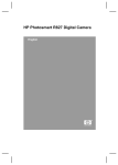
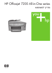
Dell OptiPlex 390 Small Form Factor Owner's Manual Regulatory Model D04S Regulatory Type D04S001 הערות ,התראות ואזהרות .הערה" :הערה" מציינת מידע חשוב המסייע להשתמש במחשב ביתר יעילות ..התראה" :התראה" מציינת נזק אפשרי לחומרה או אובדן נתונים ,במקרה של אי ציות להוראות .אזהרה" :אזהרה" מציינת אפשרות של נזק לרכוש ,פגיעה גופנית או מוות .המידע בפרסום זה עשוי להשתנות ללא הודעה .כל הזכויות שמורות © 2011 Dell Inc. - Dell Inc.חל איסור מוחלט על העתקה מכל סוג של חומרים אלה ללא הרשאה בכתב מ DELL, Dell Precision™, Precision ON™, ExpressCharge™,הלוגו : Dell™,סימנים מסחריים שבשימוש בטקסט זה Dell Inc. Intel®,הם סימנים מסחריים של ™- Wi-Fi Catcherו ™Latitude™, Latitude ON™, OptiPlex™, Vostro Intelהם סימנים מסחריים רשומים או סימנים מסחריים של ®- Celeronו ®Pentium®, Xeon®, Core™, Atom™, Centrino - AMD Opteron™, AMD Phenom™,הוא סימן מסחרי רשום ו ®. AMDבארה"ב ובמדינות אחרות Corporation Advanced Microהם סימנים מסחריים של ™- ATI FireProו ™AMD Sempron™, AMD Athlon™, ATI Radeon ו Windows Vistaהתחל( של( Startהלחצן Devices, Inc. Microsoft®, Windows®, MS-DOS®, Windows Vista®,בארצות הברית ו/או במדינות Microsoft Corporationהם סימנים מסחריים או סימנים מסחריים רשומים של ®Office Outlook וניתן ברשיון לשימוש על תקליטורים ) Blu-ray Disc Association (BDAהוא סימן מסחרי בבעלות ™. Blu-ray Discאחרות Dell Incוכל שימוש של סימן שכזה על-ידי Bluetooth® SIG, Incהיא סימן מסחרי רשום בבעלות ® Bluetoothונגנים .המילה Wireless Ethernet Compatibility Alliance, Inc.הוא סימן מסחרי רשום של ®. Wi-Fiנעשה ברשיון ייתכן שייעשה שימוש בסימנים מסחריים ובשמות מסחריים אחרים בפרסום זה כדי להתייחס לישויות הטוענות לבעלות על הסימנים .מוותרת על כל חלק קנייני בסימנים מסחריים ושמות מסחריים פרט לאלה שבבעלותה . Dell Incוהשמות ,או למוצרים שלהן 2011 — 07 Rev. A00 Contents התראות ואזהרות,הערות......................................................................................2 טיפול במחשב:1 פרק...........................................................................................7 ............................................................................................7 כלים מומלצים ................................................................................................................8 כיבוי המחשב .................................................................................................................8 לאחר עבודה בתוך גוף המחשב ...........................................................................................9 לפני עבודה בתוך גוף המחשב 2 פרק: Cover...................................................................................................11 Removing the Cover........................................................................................................11 Installing The Cover.........................................................................................................11 מסגרת קדמית:3 פרק.........................................................................................13 Removing the Front Bezel................................................................................................13 Installing The Front Bezel................................................................................................14 לשונית כרטיס ההרחבה:4 פרק............................................................................15 Removing the Expansion Card.........................................................................................15 Installing The Expansion Card.........................................................................................16 כונן אופטי:5 פרק..............................................................................................17 Removing the Optical Drive.............................................................................................17 Installing The Optical Drive.............................................................................................18 כונן קשיח:6 פרק...............................................................................................19 Removing the Hard Drive................................................................................................19 Installing The Hard Drive.................................................................................................20 זיכרון:7 פרק.....................................................................................................21 Removing the Memory....................................................................................................21 Installing The Memory.....................................................................................................22 מתג חדירה למארז:8 פרק...................................................................................23 Removing the Chassis Intrusion Switch..........................................................................23 Installing The Intrusion Switch.......................................................................................24 רמקול:9 פרק....................................................................................................25 Removing the Speaker....................................................................................................25 התקנת הרמקול .............................................................................................................26 10 פרק: Heat Sink And Processor..............................................................27 Removing the Heat Sink and Processor..........................................................................27 Installing The Heat Sink And Processor.........................................................................30 סוללת מטבע:11 פרק.........................................................................................31 Removing the Coin-Cell Battery......................................................................................31 Installing The Coin-Cell Battery.......................................................................................32 12 פרק: Power-Switch Cable......................................................................33 Removing the Power-Switch Cable................................................................................33 Installing the Power-Switch Cable..................................................................................34 13 פרק: System Fan......................................................................................35 Removing the System Fan...............................................................................................35 Installing The System Fan...............................................................................................36 פלט/ לוח קלט:14 פרק.......................................................................................37 Removing The Input/Output (I/O) Panel...........................................................................37 Installing The Input/Output (I/O) Panel............................................................................39 ספק כוח:15 פרק...............................................................................................41 Removing the Power Supply...........................................................................................41 Installing The Power Supply...........................................................................................43 ...........................................................................................45פרק :16לוח מערכת Removing the System Board...........................................................................................45 .......................................................................................................47 התקנת לוח המערכת ........................................................................................49פרק :17כלוב הכוננים Removing the Drive Cage................................................................................................49 Installing The Drive Cage................................................................................................51 .........................................................................................53פרק :18מגן המאוורר Removing the Fan Shelter...............................................................................................53 .......................................................................................................53 התקנת מגן המאוורר .......................................................................................55פרק :19הגדרת מערכת ............................................................................................................55 Boot Menu.......................................................................................................................55 Boot Menu Enhancements..............................................................................................55 תזמון רצפי מקשים ........................................................................................................56 קודי צפצוף והודעות שגיאה הנשלחות כטקסט ......................................................................56 ניווט ..........................................................................................................................57 System Setup Options.....................................................................................................57 הגדרת המערכת .........................................................................................67פרק :20פתרון בעיות Diagnostic LEDs..............................................................................................................67 ..................................................................................................................74 ..............................................................................................................77 קודי צפצוף הודעות שגיאה ...................................................................................................83פרק :21מפרט Specification...................................................................................................................83 Dell.......................................................................................91פרק :22פנייה אל Dell......................................................................................................91 פנייה אל 6 טיפול במחשב 1 לפני עבודה בתוך גוף המחשב פעל לפי הנחיות הבטיחות הבאות כדי לסייע בהגנה על המחשב מפני נזק אפשרי וכדי לסייע בהבטחת בטיחותך האישית .אלא אם צוין אחרת ,כל הליך מניח שמתקיימים התנאים הבאים: • • קראת את הוראות הבטיחות המצורפות למחשב. רכיב ניתן להחלפה או -אם נרכש בנפרד -להתקנה על ידי ביצוע הליך ההסרה בסדר הפוך. אזהרה :לפני עבודה בתוך גוף המחשב ,קרא את הוראות הבטיחות שנלוות למחשב .לקבלת מידע נוסף על נוהלי הבטיחות המומלצים ,עיין ב Regulatory Compliance Homepage-באתר www.dell.com/ .regulatory_compliance התראה :ישנם תיקונים רבים שרק טכנאי שירות מוסמך יכול לבצע .עליך לבצע פתרון בעיות ותיקונים פשוטים בלבד כפי שמתיר תיעוד המוצר ,או בהתאם להנחיות של השירות המקוון או השירות הטלפוני ושל צוות התמיכה .האחריות אינה מכסה נזק שייגרם עקב טיפול שאינו מאושר על-ידי .Dellקרא את הוראות הבטיחות המפורטות שצורפו למוצר ופעל על-פיהן. התראה :כדי למנוע פריקה אלקטרוסטטית ,פרוק מעצמך חשמל סטטי באמצעות רצועת הארקה לפרק היד או נגיעה במשטח מתכת לא צבוע ,כגון מחבר בגב המחשב. התראה :טפל ברכיבים ובכרטיסים בזהירות .אל תיגע ברכיבים או במגעים בכרטיס .החזק כרטיס בשוליו או בתושבת ההרכבה ממתכת .יש לאחוז ברכיבים כגון מעבד בקצוות ולא בפינים. התראה :בעת ניתוק כבל ,יש למשוך את המחבר או את לשונית המשיכה שלו ולא את הכבל עצמו .כבלים מסוימים מצוידים במחברים עם לשוניות נעילה; בעת ניתוק כבל מסוג זה ,לחץ על לשוניות הנעילה לפני ניתוק הכבל .בעת הפרדת מחברים ,החזק אותם ישר כדי למנוע כיפוף של הפינים שלהם .נוסף על כך ,לפני חיבור כבל ,ודא ששני המחברים מכוונים ומיושרים כהלכה. הערה :צבעי המחשב ורכיבים מסוימים עשויים להיראות שונה מכפי שהם מופיעים במסמך זה. כדי למנוע נזק למחשב ,בצע את השלבים הבאים לפני תחילת העבודה בתוך גוף המחשב. .1 .2 ודא שמשטח העבודה שטוח ונקי כדי למנוע שריטות על כיסוי המחשב. כבה את המחשב )ראה 'כיבוי המחשב'(. 7 התראה :כדי לנתק כבל רשת ,תחילה נתק את הכבל מהמחשב ולאחר מכן נתק אותו מהתקן הרשת. .3 .4 .5 .6 נתק את כל כבלי הרשת מהמחשב. נתק את המחשב ואת כל ההתקנים המחוברים משקעי החשמל שלהם. לחץ לחיצה ארוכה על לחצן ההפעלה כאשר המחשב מנותק מהחשמל כדי להאריק את לוח המערכת. הסר את הכיסוי. התראה :לפני נגיעה ברכיבים בתוך המחשב ,הארק את עצמך על-ידי נגיעה במשטח מתכת לא צבוע ,כגון המתכת על גב המחשב .במהלך העבודה ,גע מדי פעם במשטח מתכת לא צבוע כדי לפרוק חשמל סטטי, העלול לפגוע ברכיבים פנימיים. כלים מומלצים כדי לבצע את ההליכים המתוארים במסמך זה ,ייתכן שתזדקק לכלים הבאים: • • • • מברג שטוח קטן מברג פיליפס להב חיתוך קטן מפלסטיק מדיה של תוכנית עדכון Flash BIOS כיבוי המחשב התראה :כדי להימנע מאובדן נתונים ,שמור וסגור את כל הקבצים הפתוחים וצא מכל התוכניות הפתוחות לפני כיבוי המחשב. .1 כבה את מערכת ההפעלה: • ב:Windows 7- • לחץ על ) Startהתחל( ב:Windows Vista- ולאחר מכן לחץ על ) Shut Downכיבוי(. לחץ על ) Startהתחל( ,לאחר מכן לחץ על החץ בפינה הימנית התחתונה של תפריט ) Startהתחלה( כמוצג להלן ולבסוף לחץ על ) Shut Downכיבוי(. • 8 ב:Windows XP- .2 לחץ על ) Startהתחל( → ) Turn Off Computerכיבוי המחשב( → ) Turn Offכיבוי(. המחשב יכבה בתום תהליך כיבויה של מערכת ההפעלה. ודא שהמחשב וכל ההתקנים המחוברים כבויים .אם המחשב וההתקנים המחוברים לא נכבו באופן אוטומטי כאשר כיבית את מערכת ההפעלה ,לחץ והחזק את לחצן ההפעלה במשך כ6- שניות כדי לכבות אותם. לאחר עבודה בתוך גוף המחשב לאחר השלמת הליכי החלפה ,הקפד לחבר התקנים חיצוניים ,כרטיסים וכבלים לפני הפעלת המחשב. .1 החזר את הכיסוי למקומו. התראה :כדי לחבר כבל רשת ,תחילה חבר את הכבל להתקן הרשת ולאחר מכן למחשב. .2 .3 .4 .5 חבר למחשב את כבלי הטלפון או הרשת. חבר את המחשב ואת כל ההתקנים המחוברים לשקעי החשמל שלהם. הפעל את המחשב. ודא שהמחשב פועל כהלכה על-ידי הפעלת תוכנית האבחון של .Dell 9 10 2 Cover Removing the Cover .Follow the procedures in Before Working Inside Your Computer .1 .Pull up the cover-release latch at the side of the computer .2 Lift the cover upward to a 45–degree angle and remove it from the .computer .3 Installing The Cover 11 .Place the computer cover on the chassis .1 .Press down on the computer cover, until it clicks into place .2 .Follow the procedures in After Working Inside Your Computer .3 12 3 מסגרת קדמית Removing the Front Bezel 13 .Follow the procedures in Before Working Inside Your Computer .Remove the cover .Pry the front bezel retention clips away from the chassis .1 .2 .3 Rotate the bezel away from the computer to release the hooks on the .opposite edge of the bezel from the chassis .4 Installing The Front Bezel Insert the four hooks along the bottom edge of the front bezel into the slots .on the chassis front Rotate the bezel toward the computer to engage the front bezel retention .clips until they click into place .Install the cover .Follow the procedures in After Working Inside Your Computer .1 .2 .3 .4 14 4 לשונית כרטיס ההרחבה Removing the Expansion Card .Follow the procedures in Before Working Inside Your Computer .1 .Remove the cover .2 .Remove the front bezel .3 .Rotate the release tab on the card-retention latch upward .4 Pull the release lever away from the PCIe x16 card until you release the securing tab from the dent in the card. Then, ease the card up and out of its .connector and remove it from the computer .5 Pull the release lever away from the PCIe x4 card (if any) to release the securing tab from the dent in the card. Then, ease the card up and out of its .connector and remove it from the computer .6 15 Installing The Expansion Card Insert the PCIe x4 card into the connector on the system board and press .down to secure it in place Insert the PCIe x16 card (if any) into the connector on the system board and .press down to secure it in place .Install the front bezel .Install the cover .Follow the procedures in After Working Inside Your Computer .1 .2 .3 .4 .5 16 5 כונן אופטי Removing the Optical Drive .Follow the procedures in Before Working Inside Your Computer .Remove the cover .Remove the data cable and power cable from the back of the optical drive .1 .2 .3 Lift the blue tab and slide the optical drive inwards to remove it from the .computer .4 .Remove the optical drive from the bracket .5 17 Installing The Optical Drive .Insert the optical drive into the bracket .1 Lift the blue tab and slide the optical drive outwards to insert it into the .computer .Connect the data cable and power cable to the optical drive .Install the cover .Follow the procedures in After Working Inside Your Computer .2 .3 .4 .5 18 6 כונן קשיח Removing the Hard Drive .Follow the procedures in Before Working Inside Your Computer .1 .Remove the cover .2 .Remove the hard drive from the chassis .3 Press the retention clips inwards and slide the hard-drive bracket from the .drive cage .4 Flex the hard-drive bracket and then remove the single 3.5 inch hard drive .or two 2.5 inch hard drives from the bracket .5 Release the screws that secure the 2.5 inch hard drive to the top of the .hard-drive bracket .6 19 Release the screws that secure the 2.5 inch hard drive to the underside of .the hard-drive bracket .7 Installing The Hard Drive Tighten the screws to secures the two hard drives to the hard drive .bracket Flex the hard-drive bracket and then insert the single hard drive or two hard .drives into the bracket Press the retention clips inwards and slide the hard-drive bracket into the .drive cage .Install the cover .Follow the procedures in After Working Inside Your Computer .1 .2 .3 .4 .5 20 7 זיכרון Removing the Memory 21 .Follow the procedures in Before Working Inside Your Computer .Remove the cover .Remove the front bezel .Remove the drive cage .Release the memory-retention clips on each side of the memory modules .1 .2 .3 .4 .5 .Lift the memory modules out of the connectors on the system board .6 Installing The Memory Insert the memory modules into the connectors on the system board. Install .the memory modules in the order of A1 > B1 > A2 > B2 Press down on the memory modules until the retention clips spring back to .secure them in place .Install the drive cage .Install the front bezel .Install the cover .Follow the procedures in After Working Inside Your Computer .1 .2 .3 .4 .5 .6 22 8 מתג חדירה למארז Removing the Chassis Intrusion Switch 23 .Follow the procedures in Before Working Inside Your Computer .Remove the cover .Disconnect the intrusion-switch cable from system board .1 .2 .3 .Slide the intrusion switch inwards and remove it from the system board .4 Installing The Intrusion Switch Insert the intrusion switch into the chassis rear and slide it outward to .secure it .Connect the intrusion-switch cable to the system board .Install the cover .Follow the procedures in After Working Inside Your Computer .1 .2 .3 .4 24 9 רמקול Removing the Speaker .Follow the procedures in Before Working Inside Your Computer .1 .Remove the cover .2 .Remove the front bezel .3 .Remove the drive cage .4 .Disconnect the speaker cable from the system board .5 .Unthread the speaker cable from the fan shelter clip .6 Press the speaker securing tab, and slide the speaker towards the right of .the computer to release it .7 25 .8 .Remove the speaker from the chassis התקנת הרמקול .1 הנח את הרמקול במקום המתאים בחלקו האחורי של המארז. .2 לחץ על לשונית הידוק הרמקול והחלק את הרמקול לכיוון צד שמאל של המחשב כדי להדקו למקומו. .3 השחל את כבל הרמקול הפנימי לתפס מגן המאוורר. .4 חבר את כבל הרמקול ללוח המערכת. .5 התקן את כלוב הכוננים. .6 התקן את המסגרת הקדמית. .7 התקן את הכיסוי. .8 בצע את הפעולות המפורטות בסעיף לאחר העבודה בתוך גוף המחשב. 26 10 Heat Sink And Processor Removing the Heat Sink and Processor 27 .Follow the procedures in Before Working Inside Your Computer .1 .Remove the cover .2 .Remove the front bezel .3 .Remove the drive cage .4 .Disconnect the heat-sink assembly cable from the system board .5 Release the Input/Output Board or the FlyWire cable from the routing .channel on the heat sink .6 .Loosen the captive screws in the order of 1,2,3 and 4 .7 Lift the heat sink assembly upwards, and remove it from the computer. Lay the assembly with the fan facing downwards, and with the thermal grease .facing upwards .8 Press the release lever down and then move it outward to release it from .the retention hook that secures it .9 .Lift the processor cover .10 28 Lift the processor to remove it from the socket and place it in an antistatic .11 .package 29 Installing The Heat Sink And Processor Insert the processor into the processor socket. Ensure the processor is .properly seated .Lower the processor cover Press the release lever down and then move it inward to secure it with the .retention hook .Place the heat sink assembly into the chassis Tighten the captive screws to secure the heat-sink assembly to the system .board Secure the Input/Output Board or the FlyWire cable to the routing channel .on the heat sink .Connect the heat sink assembly cable to the system board .Install the drive cage .1 .2 .3 .4 .5 .6 .7 .8 .Install the front bezel .9 .Install the cover .10 .Follow the procedures in After Working Inside Your Computer .11 30 11 סוללת מטבע Removing the Coin-Cell Battery 31 .Follow the procedures in Before Working Inside Your Computer .Remove the cover .Remove the front bezel Press the coin-cell battery inward to allow the battery to pop up from the .socket .1 .2 .3 .4 .Lift the coin-cell battery out of the computer .5 Installing The Coin-Cell Battery .Place the coin-cell battery into its slot on the system board .1 .Press the coin-cell battery downwards till it is secured .Install the front bezel .Install the cover .Follow the procedures in After Working Inside Your Computer .2 .3 .4 .5 32 12 Power-Switch Cable Removing the Power-Switch Cable 33 .Follow the procedures in Before Working Inside Your Computer .1 .Remove the cover .2 .Remove the front bezel .3 .Remove the drive cage .4 .Disconnect the power-switch cable from the system board .5 .Unthread the power-switch cable from the chassis clip .6 .Pry the power-switch cable away from the chassis .7 .Slide the power-switch cable out through the front of the computer .8 Installing the Power-Switch Cable .Slide the power-switch cable in through the front of the computer .Secure the power-switch cable to the chassis .Thread the power-switch cable into the chassis clip .Connect the power-switch cable to the system board .Install the drive cage .Install the front bezel .Install the cover .Follow the procedures in After Working Inside Your Computer .1 .2 .3 .4 .5 .6 .7 .8 34 13 System Fan Removing the System Fan .Follow the procedures in Before Working Inside Your Computer .1 .Remove the cover .2 .Remove the front bezel .3 .Remove the drive cage .4 .Remove the fan shelter .5 .Disconnect the fan cable from the system board .6 .Slide the grommets inward along the groove and pass through the chassis .7 .Lift and remove the system fan from the computer .8 35 .Pry up the grommets from the system fan and remove it .9 Installing The System Fan .Insert the four grommets into the system fan .1 .Place the system fan in the chassis .2 Pass the four grommets through the chassis and slide outward along the .grooves to secure them in place .3 .Connect the fan cable to the system board .4 .Install the fan shelter .5 .Install the drive cage .6 .Install the front bezel .7 .Install the cover .8 .Follow the procedures in After Working Inside Your Computer .9 36 14 פלט/לוח קלט Removing The Input/Output (I/O) Panel 37 .Follow the procedures in Before Working Inside Your Computer .1 .Remove the cover .2 .Remove the front bezel .3 .Remove the drive cage .4 Unthread the I/O panel or the FlyWire cable from the fan-shelter clip and .heat sink .5 .Disconnect the I/O panel or the FlyWire cable from the system board .6 .Remove the single screw that secures the I/O panel to the chassis .7 Slide the I/O panel towards the right of the computer to release it from the .chassis .8 .Remove the I/O panel .9 38 Installing The Input/Output (I/O) Panel .Insert the I/O panel into the slot on the chassis front .1 Slide the I/O panel towards the left of the computer to secure to the .chassis .Tighten the screw to secure the I/O panel to the chassis .Connect the I/O panel or the FlyWire cable to the system board Thread the I/O panel or the FlyWire cable into the fan-shelter clip and the .routing on the heat sink .Install the drive cage .2 .Install the front bezel .Install the cover .Follow the procedures in After Working Inside Your Computer 39 .3 .4 .5 .6 .7 .8 .9 40 15 ספק כוח Removing the Power Supply 41 .Follow the procedures in Before Working Inside Your Computer .1 .Remove the cover .2 .Remove the front bezel .3 .Remove the drive cage .4 .Remove the fan shelter .5 .Disconnect the 4-pin power cable from the system board .6 .Unthread the 4–pin power cable from the chassis clips .7 .Disconnect the 24-pin power cable from the system board .8 Remove the screws that secure the power supply, from the back of the .computer .9 Push in on the blue release tab beside the power supply, and slide the .10 .power supply towards the front of the computer .Lift the power supply out of the computer .11 42 Installing The Power Supply .Place the power supply in the chassis and slide outward to secure it .1 Tighten the three screws securing the power supply to the back of the .computer .Connect the power cable to the system board .Thread the power cable into the chassis clips .Connect the power cable to the system board .Install the fan shelter .Install the drive cage .2 .Install the front bezel .Install the cover .3 .4 .5 .6 .7 .8 .9 .Follow the procedures in After Working Inside Your Computer .10 43 44 16 לוח מערכת Removing the System Board 45 .Follow the procedures in Before Working Inside Your Computer .1 .Remove the cover .2 .Remove the front bezel .3 .Remove the drive cage .4 .Remove the expansion cards .5 .Remove the heat sink and processor .6 .Remove the fan shelter .7 Disconnect all the cables connected to the system board, and move the .cables away from the chassis .8 Lift and release the expansion-card latch, to gain access to the screws .securing the system board .9 .Remove the screws that secure the system board to the chassis .10 .Remove the 7–mm hex screw that secures the system board to the chassis .11 .Slide the system board towards the front of the computer .12 .Remove the system board from the chassis .13 46 התקנת לוח המערכת .1 ישר את לוח המערכת עם מחברי היציאות שבגב המארז ומקם את לוח המערכת במארז. .2 .3 .4 .5 .6 חזק את הבורג המשושה 7מ"מ המהדק את לוח המערכת למארז. חזק את הברגים המהדקים את לוח המערכת למארז. סגור את תפס כרטיס ההרחבה. חבר את הכבלים ללוח המערכת. חבר את כבל מתג החדירה ,כבלי ה ,SATA-כבל לוח הקלט/פלט ,כבל מאוורר המערכת ,כבל מתג ההפעלה ,כבל הרמקול הפנימי וכבלי ספק הכוח אל לוח המערכת. התקן את מגן המאוורר. .8 .9 .10 .11 .12 .13 התקן את גוף הקירור והמעבד. התקן את כרטיס ההרחבה. התקן את כלוב הכוננים. התקן את המסגרת הקדמית. התקן את הכיסוי. בצע את הפעולות המפורטות בסעיף לאחר העבודה בתוך גוף המחשב. .7 47 48 17 כלוב הכוננים Removing the Drive Cage .Follow the procedures in Before Working Inside Your Computer .Remove the cover .Remove the front bezel .Remove the data cable and power cable from the back of the optical drive .1 .2 .3 .4 Slide the drive-cage handle toward the back of the computer into the .unlocked position .5 Rotate the drive cage upward using the handle and lift the drive cage free .off the chassis .6 49 .Remove the data cable and power cable from the back of the hard drive .7 .Remove the drive cage from the computer .8 50 Installing The Drive Cage Place the drive cage on the edge of the computer to allow access to the .cable connectors on the hard drive .Connect the data cable and power cable to the back of the hard drive Flip over the drive cage and insert it into the chassis. The drive cage tabs .are secured by the slots in the chassis Slide the drive-cage handle toward the front of the computer into the .locked position .Connect the data cable and power cable to the back of the optical drive .Install the front bezel .Install the cover .Follow the procedures in After Working Inside Your Computer 51 .1 .2 .3 .4 .5 .6 .7 .8 52 18 מגן המאוורר Removing the Fan Shelter .Follow the procedures in Before Working Inside Your Computer .1 .Remove the cover .2 .Unthread the cables in the fan shelter clip .3 .Lift the fan shelter free from the computer .4 התקנת מגן המאוורר 53 .הכנס את מגן המאוורר למחשב .1 .השחל את הכבלים לתפס מגן המאוורר .2 .התקן את הכיסוי .3 .בצע את הפעולות המפורטות בסעיף לאחר העבודה בתוך גוף המחשב .4 54 19 הגדרת מערכת הגדרת המערכת :מחשב זה מציע את האפשרויות הבאות <F2> גישה להגדרת המערכת בהקשה על <F12> פעמי בהקשה על-הצגת תפריט האתחול החד • • אם.< כדי להיכנס אל הגדרת המערכת ולערוך שינויים בהגדרות שהמשתמש יכול להגדירF2> הקש -< בפעם הראשונה שנוריות הF2> הקש,אתה נתקל בבעיות בכניסה אל הגדרת המערכת עם מקש זה . שבמקלדת מתחילות להבהבLED Boot Menu This feature gives users a quick and convenient mechanism to bypass the System Setup-defined boot device order and boot directly to a specific device .((for example: floppy, CD-ROM, or hard drive Function Keystroke one-time boot and diagnostics utility menu <Ctrl><Alt><F8> one-time boot and diagnostics utility menu <F12> Boot Menu Enhancements :The boot menu enhancements are as follows Easier access — Although the <Ctrl><Alt><F8> keystroke still exists and can be used to call up the menu, simply press <F12> during system boot to .access the menu User prompting — Not only is the menu easy to access, when you are prompted to use the keystroke on the BIOS splash screen (see image ."below). The keystroke is not "hidden Diagnostics options — The boot menu includes two diagnostic options, IDE Drive Diagnostics (90/90 Hard Drive Diagnostics) and Boot to the Utility Partition. The benefit here is that you do not have to remember the .(<Ctrl><Alt><D> and <Ctrl><Alt><F10> keystrokes (although they still work The BIOS features an option to disable either or both of the keystroke prompts :הערה .under the System Security / Post Hotkeys submenu 55 • • • When you enter the <F12> or <Ctrl><Alt><F8> keystroke correctly, the computer .beeps. The key sequence invokes the Boot Device Menu Since the one-time boot menu only affects the current boot, it has the added benefit of not requiring the technician to restore the customer's boot order after .completing troubleshooting תזמון רצפי מקשים המקלדת אינה ההתקן הראשון שתוכנית ההגדרה מאתחלת .כתוצאה מכך ,אם תבצע הקשה כלשהי מוקדם מדי ,תנעל את המקלדת .כאשר זה קורה מופיעה בצג הודעת שגיאה הנוגעת למקלדת ואינך יכול להפעיל את המערכת מחדש באמצעות צירוף המקשים >.<Ctrl><Alt><Del כדי למנוע תרחיש זה ,לפני שתתחיל בהקשה ,המתן עד שהמקלדת תאותחל .יש שתי דרכים לדעת שהמקלדת אותחלה: הנוריות במקלדת מהבהבות. במהלך האתחול ,בפינה הימנית העליונה של המסך מופיעה ההנחיה "=F2") "F2=Setupהגדרה"(. • • השיטה השנייה מתאימה במקרים בהם הצג כבר התחמם .אם הדבר טרם קרה ,המערכת לרוב מדלגת על החלון המציע הזדמנות זו לפני שאות הווידאו מופיע .במקרה זה עליך להסתמך על השיטה הראשונה -נוריות המקלדת -כדי לדעת שהמקלדת אותחלה. קודי צפצוף והודעות שגיאה הנשלחות כטקסט OptiPlex BIOSמסוגל להציג הודעות שגיאה באנגלית פשוטה ,בנוסף לקודי הצפצוף .אם הBIOS- יקבע שהאתחול הקודם לא הצליח ,תוצג הודעת שגיאה בנוסח הבא: Previous attempts at booting the system have failed at checkpoint ______. For help resolving this 56 problem, please note this checkpoint and contact )ניסיונות קודמים לאתחול המערכתDell Technical Support לקבלת עזרה בפתרון בעיה.______ נכשלו בנקודת ביקורת .(Dell רשום נקודת ביקורת זו ופנה לתמיכה הטכנית של,זו ניווט .ניתן לנווט בין הגדרות המחשב באמצעות המקלדת או העכבר :BIOS-השתמש במקשים הבאים לניווט במסכי ה הקשה פעולה –/+ או, חץ ימינה או שמאלה,<Enter> הרחבת וכיווץ שדה <> הרחבה או כיווץ של כל השדות ,יציאה/ שמירה,< — הישארות במצב ההגדרהEsc> יציאה/מחיקה BIOS-יציאה מה מקש חץ ימינה או שמאלה שינוי הגדרה <Enter> בחירת שדה לשינוי <Esc> ביטול שינוי Load Defaults < או אפשרות התפריטAlt><F> ()טען ברירות מחדל איפוס הגדרות ברירת המחדל System Setup Options NOTE: Depending on the computer and its installed devices, the items listed in this .section may or may not appear General :Displays the following information System Information: Displays BIOS Version, Service Tag, Asset Tag, Ownership Date, Manufacture Date, and the .Express Service Code Memory Information: Displays Memory Installed, Memory Available, Memory Speed, Memory Channels Mode, Memory Technology, DIMM 1 Size, DIMM 2 Size, DIMM 3 .Size, and DIMM 4 Size Processor Information: Displays Processor Type, Core Count, Processor ID, Current Clock Speed, Minimum Clock Speed, Maximum Clock Speed, Processor L2 Cache, .Processor L3 Cache, HT Capable, and 64-Bit Technology PCI Information: Displays SLOT1, SLOT2, SLOT3, SLOT4 57 • • • • System Information General Device Information: Displays SATA-0, SATA-1, SATA-2, .SATA-3, and LOM MAC Address • Allows you to specify the order in which the computer attempts to find an operating system from the devices specified in this .list USB Storage Device CD/DVD/CD-RW Drive Onboard NIC Boot Sequence • • • Allows you to set the date and time settings. Changes to the .system date and time take effect immediately Date/Time System Configuration Allows you to enable or disable the integrated network card. :You can set the integrated NIC to Disabled (Enabled (default Enabled w/PXE Enabled w/ImageServer Integrated NIC • • • • NOTE: Depending on the computer and its installed devices, .the items listed in this section may or may not appear Allows you to set the serial port settings. You can set the serial :port to Disabled Auto COM1 COM2 COM3 COM4 Serial Port • • • • • • NOTE: The operating system may allocate resources even .though the setting is disabled Allows you to configure the operating mode of the integrated .hard drive controller SATA Operation 58 System Configuration Disabled = The SATA controllers are hidden ATA = SATA is configured for ATA mode • • :Allows you to enable or disable the various drives on-board SATA-0 SATA-1 SATA-2 SATA-3 Drives • • • • This field controls whether hard drive errors for integrated drives are reported during system startup. This option is .disabled by default Smart Reporting Allows you to enable or disable the integrated USB controller :for USB Configuration Boot Support Rear Dual USB Ports Front USB Ports Rear Quad USB Ports • • • • .Allows you to enable or disable the Wi-Fi Radio Miscellaneous Devices Security 59 Allows you to set restricted access to system setup program. .This option is not set by default Administrative Password Displays the current status of the system's password security feature and allows a new system password to be assigned and .verified .This option is not set by default System Password Displays the current status of the password on the system's .(internal hard disk drive (HDD This option is not set by default Internal HDD-0 Password This option lets you enable or disable strong passwords for the .system Strong Password Security Allows you to control the minimum and maximum number of characters allowed for a administrative password and the .system password Password Configuration This option lets you bypass the System (Boot) Password and the .internal HDD password prompts during a system restart Password Bypass Disabled — Always prompt for the system and internal HDD password when they are set. This option is disabled by .default Reboot Bypass — Bypass the password prompts on .(Restarts (warm boots • • NOTE: The system will always prompt for the system and internal HDD passwords when powered on from the off state (a cold boot). Also, the system will always prompt for .passwords on any module bay HDDs that may be present This option lets you determine whether changes to the System and Hard Disk passwords are permitted when an administrator password is set. W Password Changes - This option is enabled by Allow Non-Admin Password Changes .default This field lets you Activate or Disable the BIOS module interface of the optional Computrace Service from Absolute Software. Enables or disables the optional Computrace service designed .for asset management .- This option is disabled by default Deactivate Disable Activate • • • Allows you to control the chassis intrusion feature. You can set :this option to Enable Disable On-Silent — Enabled by default if chassis intrusion is .detected Computrace Chassis Intrusion • • • Allows you to enable or disable the Execute Disable mode of the .processor. This option is enabled by default CPU XD Support 60 Security This option determines whether users are able to enter Option ROM Configuration screens via hotkeys during boot. Specifically, these settings are capable of preventing access to Intel RAID (CTRL+I) or Intel Management Engine BIOS Extension ((CTRL+P/F12 Enable — User may enter OROM configuration screens via .the hotkey One-Time Enable — User may enter OROM configuration screens via the hotkeys on next boot only. After next boot, .the setting will revert to disabled Disable — User may not enter OROM configuration screens .via the hotkey OROM Keyboard Access • • • .This option is set to Enable by default Allows you to enable or disable the option to enter Setup when Admin Setup Lockout an Administrative password is set. This option is not set by .default Performance This field specifies whether the process will have one or all .cores enabled. This option is enabled by default Multi Core Support Allows you to enable or disable the Intel SpeedStep mode of the .processor. This option is disabled by default Intel SpeedStep Allows you to enable or disable additional processor sleep .states. This option is disabled by default C States Control Allows you to enable or disable the Hyper-Threading .Technology. This option is enabled by default Hyper-Thread Control Power Management Determines how the system responds when AC power is re:applied after a power loss. You can set the AC Recovery to Power Off Power On Last State • • • .This option is Power Off by default 61 AC Recovery Power Management Sets time to automatically turn on the computer. Time is kept in standard 12-hour format (hour:minutes:seconds). Change the .startup time by typing the values in the time and AM/PM fields Auto On Time NOTE: This feature does not work if you turn off your computer using the switch on a power strip or surge .protector or if Auto Power is set to disabled .Allows you to define the controls when Deep Sleep is enabled Disabled Enabled in S5 only Enabled in S4 and S5 Deep Sleep Control • • • .This option is Disabled by default Controls the speed of the system fan. This option is disabled by .default Fan Control Override .NOTE: When enabled, the fan runs at full speed This option allows the computer to power up from the off state when triggered by a special LAN signal. This feature only works .when the computer is connected to AC power supply Disabled - Does not allow the system to power on by special LAN signals when it receives a wake-up signal from the .LAN or wireless LAN LAN Only - Allows the system to be powered on by special .LAN signals Wake on LAN • • .This option is Disabled by default POST Behavior Allows you to enable or disable the Numlock feature when your .computer starts. This option is enabled by default Numlock LED Allows you to enable or disable the keyboard error reporting .when the computer starts. This option is enabled by default Keyboard Errors Allows you to specify the function keys to display on the screen .when the computer starts POST Hotkeys (Enable F12 — Boot menu (enabled by default 62 POST Behavior This option can speed up the boot process by bypassing some :compatibility steps Minimal — The system boots quickly, unless the BIOS has been updated, memory changed, or the previous POST did .not complete Thorough — The system does not skip any steps in the boot .process Auto — This allows the operating system to control this setting (this works only when the operating system supports .(Simple Boot Flag Fast Boot • • • .This option is set to Thorough by default Virtualization Support This option specifies whether a Virtual Machine Monitor (VMM) can utilize the additional hardware capabilities provided by Intel® Virtualization Technology. Enable Intel Virtualization .Technology - This option is disabled by default Virtualization Enables or disables the Virtual Machine Monitor (VMM) from utilizing the additional hardware capabilities provided by Intel® Virtualization technology for direct I/O. Enable Intel Virtualization Technology for Direct I/O - This option is disabled .by default VT for Direct I/O Maintenance .Displays the Service Tag of your computer Service Tag Allows you to create a system asset tag if an asset tag is not .already set. This option is not set by default Asset Tag Controls the SERR message mechanism. This option is not set by default. Some graphics cards require that the SERR message .mechanism be disabled SERR Messages Image Server .Specifies how the ImageServer looks up the server address Static IP (DNS (enabled by default 63 • • Lookup Method Image Server NOTE: This field is only relevant when the "Integrated NIC" control in the "System Configuration" group is set to "Enabled ."with ImageServer Specifies the primary static IP address of the ImageServer with which the client software communicates. The default IP .address is 255.255.255.255 ImageServer IP NOTE: This field is only relevant when the "Integrated NIC" control in the "System Configuration" group is set to "Enabled with ImageServer" and when "Lookup Method" is set to .""Static IP Specifies the primary IP port of the ImageServer with which the .client communicates. The default IP port is 06910 ImageServer Port NOTE: This field is only relevant when the "Integrated NIC" control in the "System Configuration" group is set to "Enabled ."with ImageServer .Specifies how the client obtains the IP address Static IP (DNS (enabled by default Client DHCP • • NOTE: This field is only relevant when the "Integrated NIC" control in the "System Configuration" group is set to "Enabled ."with ImageServer Specifies the static IP address of the client. The default IP .address is 255.255.255.255 Client IP NOTE: This field is only relevant when the "Integrated NIC" control in the "System Configuration" group is set to "Enabled with ImageServer" and when "Client DHCP" is set to "Static ."IP Specifies the subnet mask of the client. The default setting is .255.255.255.255 Client Subnet Mask 64 Image Server NOTE: This field is only relevant when the "Integrated NIC" control in the "System Configuration" group is set to "Enabled with ImageServer" and when "Client DHCP" is set to "Static ."IP Specifies the gateway IP address for the client. The default .setting is 255.255.255.255 Client Gateway NOTE: This field is only relevant when the "Integrated NIC" control in the "System Configuration" group is set to "Enabled with ImageServer" and when "Client DHCP" is set to "Static ."IP .Displays the current license status License Status System Logs :Displays the system event log and allows you to Clear Log Mark all Entries 65 • • BIOS Events 66 20 פתרון בעיות Diagnostic LEDs The diagnostic LEDs only serve as an indicator of the progress through the :הערה Power-on Self-Test (POST) process. These LEDs do not indicate the problem that .caused the POST routine to stop The diagnostic LEDs are located on the front of the chassis next to the power button. These diagnostic LEDs are only active and visible during the POST process. Once the operating system starts to load, they turn off and are no .longer visible The system now includes pre-POST and POST LEDs in an attempt to help .identifying a possible problem with the system easier and more accurate The diagnostic lights will blink when the power button is amber or off, and will :הערה .not blink when it is blue. This has no other significance Diagnostic Light Patterns LED Power Button The computer is either turned off or is not receiving .power Re-seat the power cable in the power connector at .the back of the computer and the electrical outlet Bypass power strips, power extension cables, and other power protection devices to verify that the .computer turns on properly Ensure that any power strips being used are plugged .into an electrical outlet and are turned on Ensure that the electrical outlet is working by testing .it with another device, such as a lamp 67 • • • • Problem Description Troubleshooting Steps Ensure that the main power cable and front panel .cable are securely connected to the system board • LED Power Button .A possible system board failure has occurred Problem Description Unplug the computer. Allow one minute for the power Troubleshooting Steps to drain. Plug the computer into a working electrical .outlet and press the power button LED Power Button A possible system board, power supply, or peripheral .failure has occurred Power off computer, leaving the computer plugged in. Press and hold the power supply test button at the rear of the power supply unit. If the LED next to the switch illuminates, the problem may be with your .system board If the LED next to the switch does not illuminate, disconnect all internal and external peripherals, and press and hold the power supply test button. If it illuminates, there could be a problem with a .peripheral If the LED still does not illuminate, remove the PSU connections from the system board, then press and hold the power supply button. If it illuminates, there .could be a problem with the system board If the LED still does not illuminate, the problem is with .the power supply • Problem Description Troubleshooting Steps • • • 68 LED Power Button Memory modules are detected, but a memory power .failure has occurred If two or more memory modules are installed, remove the modules, then re-install one module and re-start the computer. If the computer starts normally, continue to install additional memory modules (one at a time) until you have identified a faulty module or reinstalled all modules without error. If only one memory module is installed, try moving it to a different .DIMM connector and re-start the computer If available, install verified working memory of the .same type into your computer • Problem Description Troubleshooting Steps • LED Power Button .BIOS may be corrupt or missing Problem Description The computer hardware is operating normally but the Troubleshooting Steps .BIOS may be corrupt or missing LED Power Button .A possible system board failure has occurred Problem Description Remove all peripheral cards from the PCI and PCI-E slots and re-start the computer. If the computer boots, Troubleshooting Steps 69 add the peripheral cards back one by one until you find .the bad one LED Power Button .Power connector not installed properly Problem Description Re-seat the 2x2 power connector from the power Troubleshooting Steps .supply unit LED Power Button Possible peripheral card or system board failure has .occurred Problem Description Remove all peripheral cards from the PCI and PCI-E slots and re-start the computer. If the computer boots, add the peripheral cards back one by one until you find .the bad one Troubleshooting Steps LED Power Button .A possible system board failure has occurred Disconnect all internal and external peripherals, and re-start the computer. If the computer boots, add the peripheral cards back one by one until you .find the bad one • Problem Description Troubleshooting Steps 70 .If the problem persists, the system board is faulty • LED Power Button .A possible coin cell battery failure has occurred Problem Description Remove the coin cell battery for one minute, reinstall Troubleshooting Steps .the battery, and restart LED Power Button .A possible processor failure has occurred Problem Description .Re-seat the processor Troubleshooting Steps LED Power Button Memory modules are detected, but a memory failure has Problem Description .occurred If two or more memory modules are installed, remove the modules, then re-install one module and re-start the computer. If the computer starts normally, continue to install additional memory modules (one at a time) until you have identified a faulty module or reinstalled all modules without .error 71 • Troubleshooting Steps If available, install working memory of the same type .into your computer • LED Power Button .A possible hard drive failure has occurred Problem Description .Re-seat all power and data cables Troubleshooting Steps LED Power Button .A possible USB failure has occurred Problem Description Re-install all USB devices and check all cable Troubleshooting Steps .connections LED Power Button .No memory modules are detected Problem Description If two or more memory modules are installed, remove the modules, then reinstall one module and restart the computer. If the computer starts normally, continue to install additional memory modules (one at a time) until you have identified a faulty module or reinstalled all modules without .error • Troubleshooting Steps 72 If available, install working memory of the same type .into your computer • LED Power Button Memory modules are detected, but a memory .configuration or compatibility error has occurred Ensure that no special requirements for memory .module/connector placement exist Ensure that the memory you are using is supported .by your computer Problem Description • Troubleshooting Steps • LED Power Button .A possible expansion card failure has occurred Problem Description Determine if a conflict exists by removing an expansion card (not a graphics card) and restarting .the computer If the problem persists, reinstall the card you removed, then remove a different card and restart .the computer Repeat this process for each expansion card installed. If the computer starts normally, troubleshoot the last card removed from the .computer for resource conflicts • Troubleshooting Steps • • LED 73 Power Button A possible system board resource and/or hardware .failure has occurred .Clear CMOS Disconnect all internal and external peripherals, and restart the computer. If the computer boots, add the peripheral cards back one by one until you .find the bad one If the problem persists, the system board / system .board component is faulty Problem Description Troubleshooting Steps • • • LED Power Button .Some other failure has occurred Ensure that the display/monitor is plugged into a .discrete graphic card Ensure that all hard drives and optical drive cables .are properly connected to the system board If there is an error message on the screen identifying a problem with a device ( hard drive), check the .device to make sure it is functioning properly If the operating system is attempting to boot from a device (optical drive), check system setup to ensure the boot sequence is correct for the devices installed .on your computer • Problem Description Troubleshooting Steps • • • קודי צפצוף למחשב יש אפשרות להשמיע סדרת צפצופים במהלך,כאשר לא ניתן להציג שגיאות או בעיות מרווח הזמן בין צפצוף לצפצוף. מזהה בעיות שונות, המכונה קודי צפצוף, סדרת הצפצופים.ההפעלה אלפיות300 שניות והצפצוף נמשך3 מרווח הזמן בין סדרות הצפצופים הוא, אלפיות שנייה300 הוא 74 שנייה .לאחר כל צפצוף ולאחר כל סדרת צפצופים ,ה BIOS-אמור לגלות אם המשתמש לחץ על לחצן ההפעלה .אם כן ,ה BIOS-יעצור את המחזוריות ויפעיל את תהליך הכיבוי הרגיל ומערכת החשמל. קוד 1-1-2 גורם כשל ברישום מיקרו-מעבד קוד 1-1-3 גורם NVRAM קוד 1-1-4 גורם כשל בסכום ביקורת ) (checksumשל ROM BIOS קוד 1-2-1 גורם קוצב זמן מרווחים הניתן לתכנות קוד 1-2-2 גורם כשל באתחול DMA קוד 1-2-3 גורם כשל בקריאה/כתיבה של רישום דף DMA קוד 1-3-1עד 2-4-4 גורם כשל בזיהוי או בשימוש ברכיבי DIMM קוד 3-1-1 גורם כשל ברישום DMAנשלט קוד 3-1-2 גורם כשל ברישום DMAראשי קוד 3-1-3 גורם כשל ברישום מסכת פסיקות ראשי קוד 3-1-4 גורם כשל ברישום מסכת פסיקות נשלט קוד 3-2-2 75 גורם כשל בטעינת וקטור פסיקה קוד 3-2-4 גורם כשל בבדיקת בקר מקלדת קוד 3-3-1 גורם אובדן אספקת חשמל לNVRAM- קוד 3-3-2 גורם תצורת NVRAM קוד 3-3-4 גורם כשל בבדיקת זיכרון מסך קוד 3-4-1 גורם כשל באתחול מסך קוד 3-4-2 גורם כשל בשחזור מסך קוד 3-4-3 גורם כשל בחיפוש ROMוידאו קוד 4–2–1 גורם אין סימון שעון קוד 4–2–2 גורם כשל בכיבוי המחשב קוד 4–2–3 גורם כשל בשער כניסה A20 קוד 4–2–4 גורם פסיקה לא צפויה במצב מוגן קוד 76 4–3–1 גורם כשל זיכרון מעל כתובת 0FFFFh קוד 4–3–3 גורם כשל בשבב קוצב זמן של מונה 2 קוד 4–3–4 גורם שעון השעה ביום נעצר קוד 4–4–1 גורם כשל בבדיקת יציאה טורית או מקבילית קוד 4–4–2 גורם כשל בפריסת קוד לזיכרון צל קוד 4–4–3 גורם כשל בבדיקת מעבד עזר מתמטי קוד 4–4–4 גורם כשל בבדיקת מטמון הודעות שגיאה לא נמצא סימן כתובת תיאור תוכנית ה BIOS-מצאה סקטור פגום בדיסק או שלא שסקטור מסוים בדיסק לא נמצא. Alert! Previous attempts at booting this system have failed at checkpoint [nnnn]. For help in resolving this problem, please note this checkpoint and contact Dell ) Technical Supportהתראה! ניסיונות קודמים לאתחול מערכת זו נכשלו בנקודת ביקורת ].[nnnn לקבלת עזרה בפתרון בעיה זו ,רשום נקודת ביקורת זו ופנה לתמיכה הטכנית של .(Dell תיאור המחשב נכשל בהשלמת תהליך האתחול שלוש פעמים ברציפות עקב אותה שגיאה .פנה אל Dellומסור לטכנאי התמיכה את קוד נקודת הביקורת )(nnnn ) Alert! Security override Jumper is installedהתראה! מותקן מגשר עקיפת אבטחה(. תיאור המגשר MFG_MODEהוגדר ותכונות ניהול ה AMT-מושבתות עד הסרתו. 77 ) Attachment failed to respondהקובץ המצורף לא הגיב( תיאור לבקר התקליטונים או הכוננים הקשיחים אין אפשרות לשלוח נתונים לכונן ששויך. ) Bad command or file nameפקודה שגויה או שם קובץ שגוי( תיאור ודא שלא שגית באיות הפקודה ,השתמשת ברווחים במקומות הנכונים והזנת את הנתיב הנכון. ) Bad error-correction code (ECC) on disk readקוד תיקון שגיאות ) (ECCשגוי בקריאת דיסק( תיאור בקר התקליטונים או הכוננים הקשיחים זיהה שגיאת קריאה שאינה ניתנת לתיקון. ) Controller has failedהבקר נכשל( תיאור הכונן הקשיח או הבקר ששויך פגומים. ) Data errorשגיאת נתונים( תיאור לתקליטון או לכונן הקשיח אין אפשרות לקרוא את הנתונים .עבור מערכת ההפעלה ,Windowsהפעל את תוכנית השירות chkdskכדי לבדוק את מבנה הקבצים של התקליטון או הכונן הקשיח .עבור מערכות הפעלה אחרות ,הפעל את תוכנית השירות המתאימה. ) Decreasing available memoryירידה בזיכרון הזמין( תיאור ייתכן שאחד או יותר ממודולי הזיכרון פגום או מותקן שלא כהלכה .התקן מחדש את מודולי הזיכרון ולאחר מכן ,במידת הצורך ,החלף אותם. ) Diskette drive 0 seek failureכשל חיפוש בכונן תקליטונים( תיאור ייתכן שיש כבל רופף ,או שפרטי תצורת המחשב אינם תואמים לתצורת החומרה. ) Diskette read failureכשל בקריאה מתקליטון( תיאור ייתכן שהתקליטון פגום או שאחד מהכבלים רופף .אם נורית הגישה לכונן דולקת ,נסה תקליטון אחר. ) Diskette subsystem reset failedאיפוס מערכת המשנה של התקליטון נכשל( תיאור ייתכן שבקר כונן התקליטונים פגום. ) Gate A20 failureכשל בשער (A20 תיאור ייתכן שאחד או יותר ממודולי הזיכרון פגום או מותקן שלא כהלכה .התקן מחדש את מודולי הזיכרון ולאחר מכן ,במידת הצורך ,החלף אותם. 78 ) General failureכשל כללי( תיאור למערכת ההפעלה אין אפשרות לבצע את הפקודה .בדרך-כלל ,לאחר הודעה זו מופיע מידע ספציפי — לדוגמה) Printer out of paper ,אין נייר במדפסת( .בצע את הפעולה המתאימה כדי לפתור את הבעיה. ) Hard-disk drive configuration errorשגיאת תצורה בכונן הקשיח( תיאור אתחול מהכונן הקשיח נכשל. ) Hard-disk drive controller failureכשל בבקר הכונן הקשיח( תיאור אתחול מהכונן הקשיח נכשל. ) Hard-disk drive failureכשל בכונן הקשיח( תיאור אתחול מהכונן הקשיח נכשל. ) Hard-disk drive read failureכשל בקריאת כונן קשיח( תיאור אתחול מהכונן הקשיח נכשל. ) Invalid configuration information-please run SETUP programפרטי תצורה לא חוקיים הפעל את תוכנית ההגדרה(תיאור פרטי תצורת המחשב אינם תואמים לתצורת החומרה. ) Invalid Memory configuration, please populate DIMM1תצורת זיכרון לא חוקית ,אכלס את (DIMM1 תיאור חריץ DIMM1לא מזהה את מודול הזיכרון .יש למקם מחדש או להתקין את המודול. ) Keyboard failureכשל במקלדת( תיאור ייתכן שאחד הכבלים או המחברים רופף ,או שהמקלדת או בקר המקלדת/העכבר פגומים. ) Memory address line failure at address; read value expecting valueכשל בשורת הכתובת של הזיכרון ברמת הכתובת ,ערך שנקרא מצפה לערך( תיאור ייתכן שאחד ממודולי הזיכרון פגום או מותקן שלא כהלכה .התקן מחדש את מודולי הזיכרון ולאחר מכן ,במידת הצורך ,החלף אותם. ) Memory allocation errorשגיאה בהקצאת זיכרון( תיאור התוכנה שאתה מנסה להפעיל מתנגשת עם מערכת ההפעלה ,עם תוכנית אחרת או עם תוכנית שירות. 79 ) Memory data line failure at address; read value expecting valueכשל בשורת הנתונים של הזיכרון ברמת הכתובת ,ערך שנקרא מצפה לערך( תיאור ייתכן שאחד ממודולי הזיכרון פגום או מותקן שלא כהלכה .התקן מחדש את מודולי הזיכרון ולאחר מכן ,במידת הצורך ,החלף אותם. ) Memory double word logic failure at address; read value expecting valueכשל לוגי מסוג כפל מילים של הזיכרון ברמת הכתובת ,ערך שנקרא מצפה לערך( תיאור ייתכן שאחד ממודולי הזיכרון פגום או מותקן שלא כהלכה .התקן מחדש את מודולי הזיכרון ולאחר מכן ,במידת הצורך ,החלף אותם. ) Memory odd/even logic failure at address, read value expecting valueכשל לוגי מסוג זוגי/אי זוגי של הזיכרון ברמת הכתובת ,ערך שנקרא מצפה לערך( תיאור ייתכן שאחד ממודולי הזיכרון פגום או מותקן שלא כהלכה .התקן מחדש את מודולי הזיכרון ולאחר מכן ,במידת הצורך ,החלף אותם ) Memory write/read failure at address; read value expecting valueכשל בקריאה/ כתיבה של הזיכרון ברמת הכתובת ,ערך שנקרא מצפה לערך( תיאור ייתכן שאחד ממודולי הזיכרון פגום או מותקן שלא כהלכה .התקן מחדש את מודולי הזיכרון ולאחר מכן ,במידת הצורך ,החלף אותם. ) Memory size in CMOS invalidגודל זיכרון ב CMOS-לא חוקי( תיאור כמות הזיכרון שנרשמה בפרטי תצורת המחשב לא תואמת לזיכרון המותקן במחשב. ) Memory tests terminated by keystrokeהקשה עצרה את בדיקות הזיכרון( תיאור הקשה עצרה את בדיקת הזיכרון. ) No boot device availableאין התקן אתחול זמין( תיאור למחשב אין אפשרות למצוא את התקליטון או הכונן הקשיח. ) No boot sector on hard-disk driveאין סקטור אתחול בכונן הקשיח( תיאור ייתכן שפרטי תצורת המחשב בהגדרת המערכת שגויים. ) No timer tick interruptאין פסיקת סימון שעון( תיאור 80 ייתכן שקיימת תקלה באחד השבבים בלוח המערכת. ) Non-system disk or disk errorדיסק ללא מערכת או שגיאה בדיסק( תיאור בתקליטון בכונן Aלא מותקנת מערכת הפעלה המאפשרת אתחול .החלף את התקליטון בתקליטון עם מערכת הפעלה המאפשרת אתחול או הוצא את התקליטון מכונן Aוהפעל את המחשב מחדש. ) Not a boot disketteתקליטון שאינו בר אתחול( תיאור מערכת ההפעלה מנסה לאתחל לתקליטון שלא הותקנה בו מערכת הפעלה המאפשרת אתחול .הכנס תקליטון בר אתחול. ) Plug and play configuration errorשגיאת תצורה של הכנס-הפעל( תיאור המחשב נתקל בבעיה בעת ניסיון להגדיר תצורה של כרטיס אחד או יותר. ) Read faultתקלת קריאה( תיאור למערכת ההפעלה אין אפשרות לקרוא מהתקליטון או מהכונן הקשיח ,המחשב לא הצליח לאתר סקטור מסוים בדיסק או שהסקטור הדרוש פגום. ) Requested sector not foundהסקטור הדרוש לא נמצא( תיאור למערכת ההפעלה אין אפשרות לקרוא מהתקליטון או מהכונן הקשיח ,המחשב לא הצליח לאתר סקטור מסוים בדיסק או שהסקטור הדרוש פגום. ) Reset failedהאיפוס נכשל( תיאור פעולת איפוס הדיסק נכשלה. ) Sector not foundסקטור לא נמצא( תיאור למערכת ההפעלה אין אפשרות לאתר סקטור מסוים בתקליטון או בכונן הקשיח. ) Seek errorשגיאת חיפוש( תיאור למערכת ההפעלה אין אפשרות למצוא רצועה מסוימת בתקליטון בכונן הקשיח. ) Shutdown failureכשל בכיבוי המחשב( תיאור ייתכן שקיימת תקלה באחד השבבים בלוח המערכת. ) Time-of-day clock stoppedשעון השעה ביום נעצר( תיאור ייתכן שהסוללה התרוקנה. 81 ) Time-of-day not set-please run the System Setup programלא הוגדרה שעה -הפעל את תוכנית הגדרת המערכת( תיאור השעה או התאריך השמורים בתוכנית הגדרת המערכת אינם תואמים לשעון המחשב. ) Timer chip counter 2 failedמונה 2של שבב קוצב הזמן נכשל( תיאור ייתכן שישנה תקלה באחד השבבים בלוח המערכת. ) Unexpected interrupt in protected modeפסיקה לא צפויה במצב מוגן( תיאור ייתכן שאירעה תקלה בבקר המקלדת או שאחד ממודולי הזיכרון רופף. WARNING: Dell's Disk Monitoring System has detected that drive [0/1] on the [primary/secondary] EIDE controller is operating outside of normal specifications. It is advisable to immediately back up your data and replace your ) .hard drive by calling your support desk or Dellאזהרה :מערכת ניטור הדיסק של Dell גילתה שפעולת כונן ] [0/1בבקר ה]ראשי/משני[ חורגת מהמפרט הרגיל .מומלץ לגבות מיד את הנתונים ולהחליף את הכונן הקשיח .לשם כך ,פנה לצוות התמיכה או אל (.Dell תיאור בעת האתחול הראשוני הכונן זיהה אפשרות לשגיאה .לאחר שהמחשב יסיים את האתחול, גבה מיידית את הנתונים והחלף את הכונן הקשיח )לקבלת פרטים על נוהלי ההתקנה ,עיין בסעיף "הוספת והסרת חלקים" המתייחס לסוג המחשב שלך( .אם אין כונן חלופי הזמין באופן מיידי והכונן אינו הכונן היחיד המאפשר אתחול ,היכנס לתוכנית הגדרת המערכת ושנה את הגדרת הכונן המתאים ל) None-ללא( .לאחר מכן הסר את הכונן מהמחשב. ) Write faultתקלת כתיבה( תיאור למערכת ההפעלה אין אפשרות לכתוב לתקליטון או לכונן הקשיח. ) Write fault on selected driveתקלת כתיבה בכונן שנבחר( תיאור למערכת ההפעלה אין אפשרות לכתוב לתקליטון או לכונן הקשיח. ) X:\ is not accessible. The device is not readyלא ניתן לגשת אל \ .X:ההתקן אינו מוכן( תיאור 82 לתקליטון אין אפשרות לקרוא את הדיסק .הכנס תקליטון לכונן ונסה שוב. 21 מפרט Specification NOTE: Offerings may vary by region. For more information regarding the configuration of your computer, click Start (or Start in Windows XP) Help and .Support, and then select the option to view information about your computer System Information Intel H61 Express Chipset System Chipset two 82C37 DMA controllers with seven independently programmable channels DMA Channels Integrated I/O APIC capability with 24 interrupts Interrupt Levels (MB (4 MB 32 (BIOS Chip (NVRAM Processor • • Processor type up to 8 MB cache depending on processor type Total Cache Intel Core i3 series Intel Core i5 series Memory 83 DDR3 Type MHz 1333 Speed two DIMM slots Connectors GB, 2 GB, and 4 GB 1 Capacity GB 1 Minimum Memory GB 8 Maximum memory Video :Video type Intel HD graphics 2000 AMD Radeon HD 6350 AMD Radeon HD 6450 Integrated Discrete • • :Video memory up to 1.7 GB shared video memory (Microsoft Windows Vista and (Windows 7 Integrated up to 1 GB Discrete Audio integrated Conexant CX20641 HD-audio codec Integrated Network integrated Realtek RTL8111E Ethernet capable of 10/100/1000 Mb/s communication Integrated Expansion Bus PCI Express 2.0, SATA 2.0, and, USB 2.0 Bus Type :PCI Express :Bus Speed x1-slot bidirectional speed – 1 GB/s x16-slot bidirectional speed – 16 GB/s • • SATA: 1.5 Gbps, and 3.0 Gbps Cards PCI Express x1 up to three full-height cards Mini-Tower up to three low-profile cards Desktop 84 Cards up to one low-profile cards Small Form Factor PCI-Express x16 up to one full-height cards Mini-Tower up to one low-profile cards Desktop up to one low-profile cards Small Form Factor Drives (Externally Accessible (5.25–inch drive bays two Mini-Tower one Desktop one slim optical drive bay Small Form Factor :Internally Accessible inch SATA drive bays–3.5 two Mini-Tower one Desktop one Small Form Factor External Connectors :Audio Back Panel three connectors once each for line-out, line-in, and microphone Mini-Tower/Desktop two connectors for line-out and line-in/microphone Small Form Factor two connectors for microphone and headphone one RJ45 connector Front Panel Network Adapter USB 2.0 Front Panel: 2 85 External Connectors Back Panel: 6 pin VGA connector, 19-pin-15 HDMI connector Video NOTE: Available video connectors may vary based .on the graphics card selected System Board Connectors PCI Express x1 data width (maximum) — one PCI Express lane three 36-pin connector Mini-Tower, Desktop one 36–pin connector Small Form Factor PCI Express x16 data width (maximum) — 16 PCI Express lanes one 164-pin connector Mini-Tower, Desktop, Small Form Factor Serial ATA four 7-pin connectors Mini-Tower,Desktop two 7-pin connectors Small Form Factor one 24-pin connectors PS2/COM connector two 240-pin connectors Memory System Fan two 3-pin connector Mini-Tower, Desktop one 5-pin connector Small Form Factor one 16-pin, two 10–pin, and one 5-pin connector Front panel control one 1155-pin connector Processor Processor Fan one 4-pin connector Mini-Tower, Desktop 86 System Board Connectors one 5-pin connector Small Form Factor one 3-pin connector Password clear jumper one 3-pin connector RTC reset jumper one 5-pin connector Internal speaker one 3-pin connector Intruder connector one 24-pin and one 4-pin connector Power connector Controls and Lights :Front of the computer Blue light — Solid blue light indicates power-on state; blinking blue light indicates sleep state of .the computer Power button light Amber light — Solid amber light when the computer does not start indicates a problem with the system board or power supply. Blinking amber light indicates a .problem with the system board Blue light — Blinking blue light indicates that the computer is reading data from or writing data to .the hard drive Drive activity light Four lights located on the front panel of the computer. For more information on the diagnostic lights, see the Service Manual at .support.dell.com/manuals Diagnostic lights :Back of the computer Green light — The power supply is turned on and is functional. The power cable must be connected to the power connector (at the back 87 Power supply diagnostic light Controls and Lights of the computer) and the electrical .outlet NOTE: You can test the health of the power system by pressing the test button. When the system power supply voltage is within specification, the self-test LED lights up. If the LED does not light up, the power supply may be defective. AC power must be connected .during this test Voltage Maximum Heat Dissipation Wattage Power VAC to 240 VAC, 50 Hz to 60 Hz, 5.0 A 100 BTU/hr 1390 W 265 Mini-Tower VAC to 240 VAC, 50 Hz to 60 Hz, 4.4 A 100 BTU/hr 1312 W 250 Desktop ;VAC to 240 VAC, 50 Hz to 60 Hz, 3.6 A 100 BTU/hr 1259 W 240 Small Form Factor V CR2032 lithium coin cell 3 Coin-cell battery .NOTE: Heat dissipation is calculated by using the power supply wattage rating Weight Depth Width Height Physical (kg (19.55 lb 8.87 cm (16.42 41.70 (inches cm (6.89 17.50 (inches cm (14.17 36.00 (inches Mini-Tower (kg (16.67 lb 7.56 cm (16.14 41.00 (inches cm (4.01 10.20 (inches cm (14.17 36.00 (inches Desktop (kg (12.57 lb 5.70 cm (12.28 31.20 (inches cm (3.65 9.26 (inches cm (11.42 29.00 (inches Small Form Factor Environmental :Temperature range 88 Environmental (C to 35 °C (50 °F to 95 °F° 10 Operating (C to 65 °C (–40 °F to 149 °F° 40– Storage :(Relative humidity (maximum (to 80% (non-condensing 20% Operating (to 95% (non-condensing 5% Storage :Maximum vibration GRMS 0.26 Operating GRMS 2.2 Storage :Maximum shock 89 G 40 Operating G 105 Storage 90 פנייה אל Dell 22 פנייה אל Dell הערה :אם אין ברשותך חיבור אינטרנט פעיל ,באפשרותך למצוא מידע ליצירת קשר בחשבונית הרכישה, תעודת המשלוח ,החשבון או קטלוג המוצרים של .Dell חברת Dellמציעה מספר אפשרויות לתמיכה ,בטלפון או דרך האינטרנט .הזמינות משתנה בהתאם למדינה ולשירות ,וייתכן כי חלק מהשירותים לא יהיה זמינים באזורך .כדי ליצור קשר עם Dellבנושאי מכירות ,תמיכה טכנית או שירות לקוחות: .1 .2 .3 .4 בקר באתר .support.dell.com בחר קטגוריית תמיכה. אם אינך לקוח בארה"ב ,בחר את קוד המדינה שלך בחלקו התחתון של הדף או בחר ) Allהכל( כדי להציג אפשרויות נוספות. בחר בקישור המתאים לשירות או לתמיכה הנחוצים. 91