1
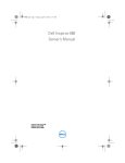
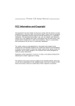
Dell™ Vostro™ 230s Service Manual—Slim Tower
Working on Your Computer
Removing and Replacing Parts
Specifications
Diagnostics
System Setup
System Board Diagram
Notes, Cautions, and Warnings
NOTE: A NOTE indicates important information that helps you make better use of your computer.
CAUTION: A CAUTION indicates potential damage to hardware or loss of data if instructions are not followed.
WARNING: A WARNING indicates a potential for property damage, personal injury, or death.
If you purchased a Dell™ n Series computer, any references in this document to Microsoft® Windows® operating systems are not applicable.
Information in this document is subject to change without notice.
© 2010 Dell Inc. All rights reserved.
Reproduction of this material in any manner whatsoever without the written permission of Dell Inc. is strictly forbidden.
Trademarks used in this text: Dell, the DELL logo, and Vostro are trademarks of Dell Inc.; Intel, Pentium, Celeron, and Core are either trademarks or registered trademarks of Intel
Corporation; Bluetooth is a registered trademark owned by Bluetooth SIG, Inc. and is used by Dell under license; Microsoft, Windows, Windows Vista, and the Windows Vista start
button are either trademarks or registered trademarks of Microsoft Corporation in the United States and/or other countries; Adobe, the Adobe logo, and Flash are either registered
trademarks or trademarks of Adobe Systems Incorporated in the United States and/or other countries; ATI FirePro is a trademark of Advanced Micro Devices, Inc.
Other trademarks and trade names may be used in this document to refer to either the entities claiming the marks and names or their products. Dell Inc. disclaims any
proprietary interest in trademarks and trade names other than its own.
March 2010 Rev. A00
Back to Contents Page
System Setup
Dell™ Vostro™ 230s Service Manual—Slim Tower
Boot Menu
Navigation Keystrokes
Entering System Setup
System Setup Menu Options
Boot Menu
Press <F12> when the Dell™ logo appears to initiate a one-time boot menu with a list of the valid boot devices for the system.
The options listed are:
Internal HDD
CD/DVD/CD-RW Drive
Onboard NIC
BIOS Setup
Diagnostics
This menu is useful when you are attempting to boot to a particular device or to bring up the diagnostics for the system. Using the boot menu does not make
any changes to the boot order stored in the BIOS.
Navigation Keystrokes
Use the following keystrokes to navigate the System Setup screens.
Navigation Keystrokes
Action
Keystroke
Expand and collapse field
<Enter>, left- or right-arrow key, or +/–
Expand or collapse all fields
<>
Exit BIOS
<Esc>—Remain in Setup, Save/Exit, Discard/Exit
Change a setting
Left or right-arrow key
Select field to change
<Enter>
Cancel modification
<Esc>
Reset defaults
<Alt><F> or Load Defaults menu option
Entering System Setup
Your computer offers the following BIOS and System Setup options:
l
l
Bring up a one-time boot menu by pressing <F12>
Access System Setup by pressing <F2>
<F12> Menu
Press <F12> when the Dell™ logo appears to initiate a one-time boot menu with a list of the valid boot devices for the computer. Diagnostics and Enter Setup
options are also included in this menu. The devices listed on the boot menu depend on the bootable devices installed in the computer. This menu is useful
when you are attempting to boot to a particular device or to bring up the diagnostics for the computer. Making changes in the boot menu does not make any
changes to the boot order stored in the BIOS.
<F2>
Press <F2> to enter System Setup and make changes to user-definable settings. If you have trouble entering System Setup using this key, press <F2> when
the keyboard lights first flash.
System Setup Menu Options
NOTE: System Setup options may vary depending on your computer and may not appear in the exact same order.
System Info
System Info The System Info page provides the basic configuration information. You cannot change these options. The following information is available:
l
l
l
l
l
l
l
l
BIOS Version
Service Tag
Processor Type
Processor L2 Cache
Installed Memory
Memory Speed
Memory Channel Mode
Memory Type
Main
System Time
System Time allows you to set the desired time (usually the current time) in the <hour><minute><second> format.
System Date
System Date allows you to set the desired date (usually the current day) in the <day><month><date><year> format.
l
l
l
l
SATA
The computer only supports two hard drives, however the system setup can support up to four SATA hard drives. When you enter System
Setup it detects the presence of SATA devices. Pressing <Enter> displays the SATA 0 - 3 sub-menus. These sub-menus displays the status of
the auto detection. The following information is displayed:
l
l
l
S.M.A.R.T.
Reporting
l
l
Disabled
Enabled (default)
During the power-on self-test (POST), the computer detects keyboard error. You can configure the BIOS to enable or disable error reporting
during POST. Available settings are:
l
l
Fan Errors
Auto (default)
Off
During the power-on self-test (POST), the computer stops if the system setup detects a hardware error. You can configure the system setup to
ignore certain errors during POST and continue the boot-up process. Available settings are:
l
Keyboard
Errors
Device
Vendor
Size (only displayed when the Hard Drive is detected)
This field controls whether errors for integrated drives are reported while booting the computer. This technology is part of the SMART (Self
Monitoring Analysis and Reporting Technology) specification.
l
Halt On Error
Day — Choose the day of the week, defined by BIOS (read-only)
Month — Choose the month
Date — Choose the date, which you can change using the keyboard.
Year — Set the year.
Report (default)
Do not report
During the power-on self-test (POST), the computer detects fan error. You can configure the BIOS to enable or disable error reporting during
POST. Available settings are:
l
l
Report (default)
Do not report
Advanced
CPU Information
Max CPUID Value Limit — The maximum CPUID input value determines the values that the operating system can write to the CPUID's
EAX register to obtain information about the processor. Available Settings are:
l
l
Enable
Disable (default)
Intel® Virtualization Tech — Intel® Virtualization Technology (Intel® VT) is comprised of a set of processor enhancements that improve
traditional software-based virtualization solutions. Allows a computer to run multiple operating systems and applications as independent
virtual machines. Using virtualization capabilities, one computer can function as multiple "virtual" computers. Available Settings are:
l
l
Enable (default)
Disable
Execute Disable Bit — Execute Disable Bit (EDB) is an Intel hardware-based security feature that can help reduce your computers
exposure to viruses and malicious code. This feature allows the processors to specify areas on the memory where application codes can
or cannot execute. When a malicious worm attempts to insert code in the buffer, the processor disables the code's execution, preventing
damage and worm propagation. Available Settings are:
l
l
Enable (default)
Disable
Initiate Graphic Adapter — Allows you to enable or disable the VGA controller. Available Settings are:
l
l
l
PEG/PCI (default)
PEG
PCI
Video Memory Size — Allows you to set the size of the Video Memory. Available Settings are:
l
l
l
Integrated
Graphics
Configuration
32 MB (default)
64 MB
128 MB
DVMT Model Select — Intel's Dynamic Video Memory Technology (DVMT) allows the computer to dynamically allocate memory resources
according to the demands of the computer at any point in time. The DVMT improves the efficiency of the memory allocated to either
computer's or graphic's processor. Available Settings are:
l
l
DVMT Mode (default)
UMA Mode
DVMT/FIXED Memory — Allows you to set the size of the DVMT/FIXED Memory. Available Settings are:
l
l
l
Integrated
Peripherals
Configuration
128 MB
256 MB (default)
Maximum DVMT
ATA/IDE Configuration —
l
l
l
Disabled
Compatible
PEG/PCI (default)
USB Functions —
l
l
Enabled (default)
Disabled
USB Storage Functions —
l
l
Enabled (default)
Disabled
Audio Controller —
l
l
Enabled (default)
Disabled
Integrated NIC —
l
l
Enabled (default)
Disabled
LAN Boot ROM —
l
l
Enabled (default)
Disabled
Serial Port Address —
l
l
l
l
3F8/IRQ4 (default)
2F8/IRQ3
3E8/IRQ4
2E8/IRQ3
Bootup Num-Lock —
l
l
On (default)
Off
Quick Boot —
l
l
Enabled (default)
Disabled
Power
Low Power
Mode
Enables or disables low power mode.
This option is disabled by default.
When low power mode is enabled, the integrated network card is disabled when the computer shuts down or hibernates. Only add-in
network cards will be able to remotely wake the computer.
Suspend mode
Sets the energy-saving mode of the ACPI function. It determines the Standby mode in the operating system. Available settings are:
l
l
S1 (POS)
S3 (STR) (default)
When you select S1 (POS) mode, the power does not shut off and the supply status remains as it is. But when you select S3 (STR) mode, the
power is cut off after a delay. The computer’s status before it enters STR is saved in memory, and the computer can quickly return to that
previous status when the STR function wakes.
USB Wakeup
From S3
Allows the system to wake up from USB peripheral that supports wake from USB. Available settings are:
l
l
Restore on AC
Power Loss
Determines what action the computer will take when power is restored. Available settings are:
l
l
l
Resume by PS2
Enabled (default)
Disabled
Last State
On
Off (default)
Allows the computer to resume back after go to standby using PS2 Devices. Available settings are:
Devices
l
l
Resume on LAN
Allows the system to resume from an onboard LAN, PCIE-X1 LAN card, or a PCI LAN card. Available settings are:
l
l
Resume on RTC
Alarm
Enabled (default)
Disabled
Enabled
Disabled (default)
You can set the alarm to enabled and key in Data/time to power on system Available settings are:
l
l
Enabled
Disabled (default)
Security
Supervisor
Password
Provides restricted access to the computer's system setup program in the same way that access to the system can be restricted with the
System Password option.
This option is not set by default.
Boot
Boot Sequence
Back to Contents Page
Specifies the Boot Device Priority sequence from available devices.
Back to Contents Page
Diagnostics
Dell™ Vostro™ 230s Service Manual—Slim Tower
Dell Diagnostics
Power Button Light Codes
Beep Codes
Dell Diagnostics
When to Use the Dell Diagnostics
It is recommended that you print these procedures before you begin.
NOTE: The Dell Diagnostics software works only on Dell computers.
NOTE: The Drivers and Utilities media is optional and may not ship with your computer.
Enter system setup (see Entering System Setup), review your computer's configuration information, and ensure that the device you want to test displays in
System Setup and is active.
Start the Dell Diagnostics from either your hard drive or from the Drivers and Utilities media.
Starting the Dell Diagnostics From Your Hard Drive
1.
Turn on (or restart) your computer.
2.
When the DELL logo appears, press <F12> immediately.
NOTE: If you see a message stating that no diagnostics utility partition has been found, run the Dell Diagnostics from your Drivers and Utilities media.
If you wait too long and the operating system logo appears, continue to wait until you see the Microsoft® Windows® desktop. Then shut down
your computer and try again.
3.
When the boot device list appears, highlight Boot to Utility Partition and press <Enter>.
4.
When the Dell Diagnostics Main Menu appears, select the test that you want to run.
Starting the Dell Diagnostics From the Drivers and Utilities Disc
1.
Insert the Drivers and Utilities disc.
2.
Shut down and restart the computer.
When the DELL logo appears, press <F12> immediately.
If you wait too long and the Windows logo appears, continue to wait until you see the Windows desktop. Then shut down your computer and try again.
NOTE: The next steps change the boot sequence for one time only. On the next startup, the computer boots according to the devices specified in the
system setup program.
3.
When the boot device list appears, highlight Onboard or USB CD-ROM Drive and press <Enter>.
4.
Select the Boot from CD-ROM option from the menu that appears and press <Enter>.
5.
Type 1 to start the menu and press <Enter> to proceed.
6.
Select Run the 32 Bit Dell Diagnostics from the numbered list. If multiple versions are listed, select the version appropriate for your computer.
7.
When the Dell Diagnostics Main Menu appears, select the test you want to run.
Dell Diagnostics Main Menu
1.
After the Dell Diagnostics loads and the Main Menu screen appears, click the button for the option you want.
Option
Function Express Test Performs a quick test of devices. This test typically takes 10 to 20 minutes and requires no interaction on your part. Run Express Test first to
increase the possibility of tracing the problem quickly.
Extended
Test
Performs a thorough check of devices. This test typically takes 1 hour or more and requires you to answer questions periodically.
Custom Test
Tests a specific device. You can customize the tests you want to run.
Symptom
Tree
Lists the most common symptoms encountered and allows you to select a test based on the symptom of the problem you are having.
2.
If a problem is encountered during a test, a message appears with an error code and a description of the problem. Write down the error code and
problem description and follow the instructions on the screen.
3.
If you run a test from the Custom Test or Symptom Tree option, click the applicable tab described in the following table for more information.
Tab
Function Results
Displays the results of the test and any error conditions encountered.
Errors
Displays error conditions encountered, error codes, and the problem description.
Help
Describes the test and may indicate requirements for running the test.
Configuration Displays your hardware configuration for the selected device.
The Dell Diagnostics obtains configuration information for all devices from system setup, memory, and various internal tests, and it displays
the information in the device list in the left pane of the screen. The device list may not display the names of all the components installed on
your computer or all devices attached to your computer.
Parameters
Allows you to customize the test by changing the test settings.
4.
When the tests are completed, if you are running the Dell Diagnostics from the Drivers and Utilities disc, remove the disc.
5.
Close the test screen to return to the Main Menu screen. To exit the Dell Diagnostics and restart the computer, close the Main Menu screen.
Power Button Light Codes
The diagnostic lights give much more information about the system state, but legacy power light states are also supported in your computer. The power light
states are shown in following table.
Power Light
State
Description
Off
Power is off, light is blank. The computer is either turned off or is not receiving power.
Solid Blue
Power light is steady blue and the computer is not responding, ensure that the display is connected and powered on.
Blinking
Blue
Blinking
Amber
Indicates the computer is in standby mode. Press a key on the keyboard, move the mouse, or press the power button to resume normal
operation. If the power light is blinking amber, the computer is receiving electrical power, a device such as a memory module or graphics card
might be malfunctioning or incorrectly installed.
Indicates the computer is receiving electrical power but a device such as a memory module or graphics card might be malfunctioning or
incorrectly installed.
Solid Amber
Indicates the computer is facing the power issue or an internal device is malfunctioning.
Beep Codes
If the monitor cannot display error messages during the POST, the computer may emit a series of beeps that identifies the problem or that can help you
identify a faulty component or assembly. The following table lists the beep codes that may be generated during the POST. Most beep codes indicate a fatal
error that prevents the computer from completing the boot routine until the indicated condition is corrected.
Code Cause
Cause
1
BIOS checksum failure.
Possible system board failure. Contact Dell.
2
No memory modules are
detected
1.
2.
3.
If you have two or more memory modules installed, remove the modules, reinstall one module, and then
restart the computer. If the computer starts normally, reinstall an additional module. Continue until you have
identified a faulty module or reinstalled all modules without error.
If available, install good memory of the same type into your computer.
If the problem persists, contact Dell.
3
Possible system board failure
4
RAM Read/Write failure
5
Real-time clock failure. Possible
battery failure or system board
failure.
Replace the battery. If the problem persists, contact Dell.
6
Video BIOS Test Failure
Contact Dell.
7
CPU-cache test failure
Contact Dell.
Back to Contents Page
Contact Dell.
1.
2.
3.
Ensure that no special memory module/memory connector placement requirements exist.
Verify that the memory modules that you are installing are compatible with your computer.
If the problem persists, contact Dell.
Back to Contents Page
Removing and Replacing Parts
Dell™ Vostro™ 230s Service Manual—Slim Tower
Cover
Front Bezel
Chassis Support Bracket
Expansion Card Memory
Optical Drive
Hard Drive
Fan Power Button and Card Reader Light Cables
Front I/O Panel and SD Card Reader
Coin-Cell Battery
Heat Sink and Processor
Power Supply System Board
Rubber Foot
Back to Contents Page
Back to Contents Page
Specifications
Dell™ Vostro™ 230s Service Manual—Slim Tower
System Information
Processor
Video
Memory
Network
Audio
Expansion Bus
Cards
External Connectors
Drives
Systemboard Connectors
Controls and Lights
Power
Physical
Environmental
NOTE: Offerings may vary by region. For more information regarding the configuration of your computer, click Start® Help and Support and select the
option to view information about your computer.
Processor
Intel® Core™2 Quad
Intel Core2 Duo
Intel Pentium® Dual Core
Intel Celeron®
Type
System Information
Chipset
Intel G41 Express Chipset
Front Side Bus (FSB)
800 MHz, 1066 MHz, or 1333 MHz
Memory
Type
DDR3 1066 MHz
Connectors
two DIMM slots
Capacity
1 GB or 2 GB
Minimum memory
1 GB
Maximum memory
4 GB
Video
Type:
Discrete:
Mini Tower
PCI-E x16 full-height graphics card
Slim Tower
PCI-E x16 half-height graphics card
Integrated VGA (on system board)
Intel GMA X4500
Memory:
Discrete
NVIDIA GeForce G310 - 512 MB (for Mini Tower and
Slim Tower)
NVIDIA GeForce GT 220 (for Mini Tower only) - 1 GB
Integrated VGA (on system board)
Up to 512 MB shared video memory (with 1 GB
system memory)
Audio
Type
Realtek ALC662 (5.1 Channel audio)
Network
Integrated
Broadcom NetLink 57788 10/100/1000 Mb/s
Expansion Bus
Bus type
PCI 2.3
PCI Express Gen1 (PCIe-x16) from G41
PCI Express 1.0a (PCIe-x1) from ICH7
SATA 1.0 and 2.0
USB 2.0
Bus speed
133 MB/s (PCI)
x1-slot bidirectional speed — 500 MB/s (PCI Express)
x16-slot bidirectional speed — 8 GB/s (PCI Express)
1.5 Gbps and 3.0 Gbps (SATA)
480-Mbps high speed, 12-Mbps full speed, 1.2-Mbps
low speed (USB)
PCI cards:
Connectors
one PCIe x16
one PCIe x1
two PCI
Cards
PCI
two full height and ¾ length cards (for Mini Tower)
two low profile cards (for Slim Tower)
PCI Express x1
one full height and ¾ length card (for Mini Tower)
one low profile card (for Slim Tower)
PCI Express x16
one full height and ¾ length card (for Mini Tower)
one low profile card (for Slim Tower)
Drives
Mini Tower
Slim Tower
Externally accessible:
3.5-inch drive bays
one
none
5.25-inch drive bays
two
one
two
two
3.5-inch SATA hard drives
two
two
5.25-inch SATA
DVD-ROM,
DVD/CD-RW, and DVD+/-RW drives
two
one
Internally accessible:
3.5-inch drive bays
Available devices:
External Connectors
Audio:
back panel
three connectors for line-in, line-out, and microphone
front panel
two connectors for microphone and headphone
Network adapter
one RJ45 connector
USB:
internal
two
front panel
two
back panel
four
Video
15-pin VGA connector
Systemboard Connectors
PCI 2.3:
connectors
two 124-pin connectors
data width (maximum)
32 bits
PCI Express x1:
connectors
one 36-pin connector
data width (maximum)
one PCI-Express lane
PCI Express x16:
connectors
one 164-pin connector
data width (maximum)
16 PCI-Express lanes
Serial ATA
four 7-pin connectors
Memory
two 240-pin connectors
Internal USB device
one 10-pin connector (supports two USB ports)
Processor fan
one 4-pin connector
System fan
one 3-pin connector
Front panel control
one 10-pin connector
Front panel audio HDA header
one 10-pin connector
Processor
one 775-pin connector
Power 12V
one 4-pin connector
Power
one 24-pin connector
Controls and Lights
Front of the computer:
Power button
push button
Power light
Solid blue light — indicates power-on state.
Blinking blue light — indicates sleep state of the
computer.
Solid amber light (when the computer does
not start) — indicates a problem with the system
board or power supply.
Blinking amber light — indicates a problem with the
system board.
Drive activity light
Back of the computer:
Green light — A blinking green light indicates the
computer is reading data from or writing data to the
SATA hard drive or CD/DVD.
Network activity light
(on integrated network adapter)
Yellow light — A good connection exists between the
network and the computer.
Off (no light)— The computer is not detecting a
physical connection to the network.
Power supply diagnostic light
Green — A green light indicates that the 5 V standby
power is OK.
Power
Mini Tower
Slim Tower
DC power supply:
Wattage
300 W
250 W
Maximum heat dissipation (MHD)
1338 BTU/hr
1233 BTU/hr
Voltage
115/230 VAC, 50/60 Hz,
9.0A/4.5A
115/230 VAC,
50/60 Hz,
8.0A/4.0A
Coin-cell battery
3 V CR2032 lithium coin cell
NOTE: Heat dissipation is calculated by using the power supply wattage rating.
NOTE: See the safety information that shipped with your computer for important voltage setting information.
Physical
Mini Tower
Slim Tower
Height
37.00 cm (14.50 inches)
37.30 cm (14.60
inches)
Width
17.00 cm (6.70 inches)
10.60 cm (4.20
inches)
Depth
42.70 cm (16.90 inches)
43.70 cm (17.20
inches)
Weight
6.10 kg (13.50 lb)
5.80 kg (12.80 lb)
Environmental
Temperature:
Operating
10 °C to 35 °C (50 °F to 95 °F)
Storage
–40 °C to 65 °C (–40 °F to 149 °F)
Relative humidity
20% to 80% (noncondensing)
Maximum vibration:
Operating
5–350 Hz at 0.0002 G2/Hz
Storage
5–500 Hz at 0.001 to 0.01 G2/Hz
Maximum shock:
Operating
40 G +/– 5% with pulse duration of 2 msec +/– 10%
(equivalent to 20 in/sec [51 cm/sec])
Storage
105 G +/– 5% with pulse duration of 2 msec +/– 10%
(equivalent to 50 in/sec [127 cm/sec])
Altitude:
Operating
–15.2 m to 3048 m (–50 ft to 10,000 ft)
Storage
–15.2 m to 10,668 m (–50 ft to 35,000 ft)
Airborne contaminant level
Back to Contents Page
G2 or lower as defined by ISA-S71.04-1985
Back to Contents Page
Chassis Support Bracket
Dell™ Vostro™ 230s Service Manual—Slim Tower
WARNING: Before working inside your computer, read the safety information that shipped with your computer. For additional safety best
practices information, see the Regulatory Compliance Homepage at www.dell.com/regulatory_compliance.
Removing the Chassis Support Bracket
NOTE: You may need to install Adobe® Flash® Player from Adobe.com in order to view the illustrations below.
1.
2.
3.
Follow the procedures in Before Working Inside Your Computer.
Remove the cover.
Remove the screw that secures the chassis support bracket to the computer.
4.
Lift and remove the support bracket out of the computer.
Replacing the Chassis Support Bracket
To replace the chassis support bracket, perform the above steps in reverse order.
Back to Contents Page
Back to Contents Page
Fan
Dell™ Vostro™ 230s Service Manual—Slim Tower
WARNING: Before working inside your computer, read the safety information that shipped with your computer. For additional safety best
practices information, see the Regulatory Compliance Homepage at www.dell.com/regulatory_compliance.
Removing the Fan
NOTE: You may need to install Adobe® Flash® Player from Adobe.com in order to view the illustrations below.
1.
2.
3.
4.
5.
6.
Follow the procedures in Before Working Inside Your Computer.
Remove the cover.
Remove the front bezel.
Remove the chassis support bracket.
Remove the hard drive.
Disconnect the fan cable from the system board.
7.
Remove the the fan cable from the tabs on the computer.
8.
Remove the screws that secure the fan to the computer.
9.
Remove the fan from the computer.
Replacing the Fan
To replace the fan, perform the above steps in reverse order.
Back to Contents Page
Back to Contents Page
Coin-cell Battery
Dell™ Vostro™ 230s Service Manual—Slim Tower
WARNING: Before working inside your computer, read the safety information that shipped with your computer. For additional safety best
practices information, see the Regulatory Compliance Homepage at www.dell.com/regulatory_compliance.
Removing the Coin-cell Battery
NOTE: You may need to install Adobe® Flash® Player from Adobe.com in order to view the illustrations below.
1.
2.
3.
4.
5.
Follow the procedures in Before Working Inside Your Computer.
Remove the cover.
Remove the front bezel.
Remove the chassis support bracket.
Press the release latch to release the coin-cell battery from the socket.
6.
Remove the battery from the computer.
Replacing the Coin-cell Battery
To replace the coin-cell battery, perform the above steps in reverse order.
Back to Contents Page
Back to Contents Page
Cover
Dell™ Vostro™ 230s Service Manual—Slim Tower
WARNING: Before working inside your computer, read the safety information that shipped with your computer. For additional safety best
practices information, see the Regulatory Compliance Homepage at www.dell.com/regulatory_compliance.
Removing the Cover
NOTE: You may need to install Adobe® Flash® Player from Adobe.com in order to view the illustrations below.
1.
2.
Follow the procedures in Before Working Inside Your Computer.
Remove the thumbscrews that secure the cover to the computer.
3.
Slide the cover towards the back of the computer.
4.
Lift up and remove the cover from the computer.
Replacing the Cover
To replace the cover, perform the above steps in reverse order.
Back to Contents Page
Back to Contents Page
Expansion Card(s)
Dell™ Vostro™ 230s Service Manual—Slim Tower
WARNING: Before working inside your computer, read the safety information that shipped with your computer. For additional safety best
practices information, see the Regulatory Compliance Homepage at www.dell.com/regulatory_compliance.
Removing an Expansion Card
NOTE: You may need to install Adobe® Flash® Player from Adobe.com in order to view the illustrations below.
1.
2.
3.
4.
Follow the procedures in Before Working Inside Your Computer.
Remove the cover.
Remove the chassis support bracket.
Grasp the card by its top corners, and ease the card from its connector.
Replacing Expansion Cards
To replace an expansion card, perform the above steps in reverse order.
Back to Contents Page
Back to Contents Page
Front Bezel
Dell™ Vostro™ 230s Service Manual—Slim Tower
WARNING: Before working inside your computer, read the safety information that shipped with your computer. For additional safety best
practices information, see the Regulatory Compliance Homepage at www.dell.com/regulatory_compliance.
Removing the Front Bezel
NOTE: You may need to install Adobe® Flash® Player from Adobe.com in order to view the illustrations below.
1.
2.
3.
Follow the procedures in Before Working Inside Your Computer.
Remove the cover.
Gently pry the retention clips away from the chassis to release the bezel from the computer.
4.
Rotate and release the bezel from the computer.
Replacing the Front Bezel
To replace the front bezel, perform the above steps in reverse order.
Back to Contents Page
Back to Contents Page
Front I/O Panel and SD Card Reader
Dell™ Vostro™ 230s Service Manual—Slim Tower
WARNING: Before working inside your computer, read the safety information that shipped with your computer. For additional safety best
practices information, see the Regulatory Compliance Homepage at www.dell.com/regulatory_compliance.
Removing the Front I/O Panel and SD Card Reader
NOTE: You may need to install Adobe® Flash® Player from Adobe.com in order to view the illustrations below.
1.
2.
3.
4.
5.
6.
7.
8.
Follow the procedures in Before Working Inside Your Computer.
Remove the cover.
Remove the front bezel.
Remove the chassis support bracket.
Remove the hard drive.
Remove the optical drive.
Remove the power button and card reader light cables.
Disconnect all the cables from the system board.
9.
Unthread the cables from their routing clips on the chassis.
10.
Remove the screws that secure the I/O panel to the computer.
11.
Gently slide the I/O panel towards the bottom of the computer and remove the I/O panel from the chassis.
12.
Release the two securing clips and push up the SD card reader.
13.
Remove the SD card reader from the I/O panel bracket.
Replacing the Front I/O Panel and SD Card Reader
To replace the front I/O panel and SD card reader, perform the above steps in reverse order.
Back to Contents Page
Back to Contents Page
Hard Drive
Dell™ Vostro™ 230s Service Manual—Slim Tower
WARNING: Before working inside your computer, read the safety information that shipped with your computer. For additional safety best
practices information, see the Regulatory Compliance Homepage at www.dell.com/regulatory_compliance.
Removing the Hard Drive
NOTE: You may need to install Adobe® Flash® Player from Adobe.com in order to view the illustrations below.
1.
2.
3.
4.
5.
Follow the procedures in Before Working Inside Your Computer.
Remove the cover.
Remove the front bezel.
Remove the chassis support bracket.
Disconnect the power cable and data cable from the hard drive.
6.
Press and hold the drive release latch and push the hard drive towards the back of the computer.
7.
Lift and remove the hard drive from the drive bay.
Replacing the Hard Drive
To replace the hard drive, perform the above steps in reverse order.
Back to Contents Page
Back to Contents Page
Heat Sink and Processor
Dell™ Vostro™ 230s Service Manual—Slim Tower
WARNING: Before working inside your computer, read the safety information that shipped with your computer. For additional safety best
practices information, see the Regulatory Compliance Homepage at www.dell.com/regulatory_compliance.
Removing the Heat Sink and Processor
NOTE: You may need to install Adobe® Flash® Player from Adobe.com in order to view the illustrations below.
1.
2.
3.
4.
Follow the procedures in Before Working Inside Your Computer.
Remove the cover.
Remove the chassis support bracket.
Disconnect the heat sink cable from the system board.
5.
Loosen the captive screws that secure the heat sink and fan assembly to the system board.
6.
Lift the heat sink assembly and remove it from the computer. Lay the assembly on a clean work surface with the fan facing downward and the bottom
facing upward.
7.
Press down and slide the lever to release the processor cover.
8.
Lift the processor cover.
9.
Carefully lift and remove the processor from its socket, and place it into an antistatic package.
Replacing the Heat Sink and Processor
To replace the heat sink and processor, perform the above steps in reverse order.
Back to Contents Page
Back to Contents Page
Module
Dell™ Vostro™ 230s Service Manual—Slim Tower
WARNING: Before working inside your computer, read the safety information that shipped with your computer. For additional safety best
practices information, see the Regulatory Compliance Homepage at www.dell.com/regulatory_compliance.
Removing a Memory Module
NOTE: You may need to install Adobe® Flash® Player from Adobe.com in order to view the illustrations below.
1.
2.
3.
Follow the procedures in Before Working Inside Your Computer.
Remove the cover.
Press the securing clip at each end of the memory module connector to release the module from the computer. 4.
Remove the memory module from the computer.
Replacing a Memory Module
To replace a memory module, perform the above steps in reverse order.
Back to Contents Page
Back to Contents Page
Optical Drive
Dell™ Vostro™ 230s Service Manual—Slim Tower
WARNING: Before working inside your computer, read the safety information that shipped with your computer. For additional safety best
practices information, see the Regulatory Compliance Homepage at www.dell.com/regulatory_compliance.
Removing the Optical Drive
NOTE: You may need to install Adobe® Flash® Player from Adobe.com in order to view the illustrations below.
1.
2.
3.
4.
5.
Follow the procedures in Before Working Inside Your Computer.
Remove the cover.
Remove the front bezel.
Remove the chassis support bracket.
Disconnect the power cable and data cable from the optical drive.
6.
Press and hold the drive release latch, then slide the optical drive through the front bezel and out of the computer.
Replacing the Optical Drive
To replace the optical drive, perform the above steps in reverse order.
Back to Contents Page
Back to Contents Page
Power Button and Card Reader Light
Dell™ Vostro™ 230s Service Manual—Slim Tower
WARNING: Before working inside your computer, read the safety information that shipped with your computer. For additional safety best
practices information, see the Regulatory Compliance Homepage at www.dell.com/regulatory_compliance.
Removing the Power Button and Card Reader Light
NOTE: You may need to install Adobe® Flash® Player from Adobe.com in order to view the illustrations below.
1.
2.
3.
4.
5.
6.
Follow the procedures in Before Working Inside Your Computer.
Remove the cover.
Remove the front bezel.
Remove the chassis support bracket.
Remove the optical drive.
Press the plastic tabs inward to release the power button and card reader light cables from the chassis.
7.
Unthread the power button and card reader light cables from their routing clip.
8.
Disconnect the power button and card reader light cables from the system board and remove them from the computer. Replacing the Power Button and Card Reader Light
To replace the power button and card reader light, perform the above steps in reverse order.
Back to Contents Page
Back to Contents Page
Power Supply
Dell™ Vostro™ 230s Service Manual—Slim Tower
WARNING: Before working inside your computer, read the safety information that shipped with your computer. For additional safety best
practices information, see the Regulatory Compliance Homepage at www.dell.com/regulatory_compliance.
Removing the Power Supply
NOTE: You may need to install Adobe® Flash® Player from Adobe.com in order to view the illustrations below.
1.
2.
3.
4.
Follow the procedures in Before Working Inside Your Computer.
Remove the cover.
Remove the chassis support bracket.
Disconnect all the power cables from the system board and the drives.
5.
Remove the screws that secure the power supply to the computer.
6.
Press down on the power supply release latch and slide the power supply back slightly.
7.
Pivot the power supply away from the chassis and lift it up and out of the computer.
Replacing the Power Supply
To replace the power supply, perform the above steps in reverse order.
Back to Contents Page
Back to Contents Page
Rubber Foot
Dell™ Vostro™ 230s Service Manual—Slim Tower
WARNING: Before working inside your computer, read the safety information that shipped with your computer. For additional safety best
practices information, see the Regulatory Compliance Homepage at www.dell.com/regulatory_compliance.
Removing the Rubber Foot
NOTE: You may need to install Adobe® Flash® Player from Adobe.com in order to view the illustrations below.
1.
2.
3.
4.
5.
Follow the procedures in Before Working Inside Your Computer.
Remove the cover.
Remove the chassis support bracket.
Remove the power supply.
Rotate the rubber foot and remove it from the computer.
Replacing the Rubber Foot
To replace the rubber foot, perform the above steps in reverse order.
Back to Contents Page
Back to Contents Page
System Board
Dell™ Vostro™ 230s Service Manual—Slim Tower
WARNING: Before working inside your computer, read the safety information that shipped with your computer. For additional safety best
practices information, see the Regulatory Compliance Homepage at www.dell.com/regulatory_compliance.
Removing the System Board
NOTE: You may need to install Adobe® Flash® Player from Adobe.com in order to view the illustrations below.
1.
2.
3.
4.
5.
6.
7.
Follow the procedures in Before Working Inside Your Computer.
Remove the cover.
Remove the chassis support bracket.
Remove the memory.
Remove the heat sink and processor.
Remove any expansion cards
Disconnect all cables from the system board.
8.
Remove the screws that secure the system board to the computer.
9.
Slide the system board toward the front of the computer and carefully lift the system board out of the computer.
Replacing the System Board
To replace the system board, perform the above steps in reverse order.
Back to Contents Page
Back to Contents Page
System Board Layout
Dell™ Vostro™ 230s Service Manual—Slim Tower
1
Power connector (PWR1)
2
Processor heat sink/fan assembly power (CPUFAN1)
3
Memory module connectors (2)
4
Main power connector
5
Battery socket
6
Serial ATA drive connector (SATA3)
7
Serial ATA drive connector (SATA2)
8
Serial ATA drive connector (SATA0)
9
Serial ATA drive connector (SATA1)
10 Chassis fan connector 2(SYS FAN2)
11
Power button & LED connector(LEDH1) 12 Front I/O panel connector (USBF1)
13
Card reader connector (USBF_INT1)
14 CMOS jumper (CMOS1)
15
Password jumper (PW_CLR1)
16 Audio connector (AUDIOF1)
17
PCI connector (PCI1)
18 PCI connector (PCI2)
19
Audio connectors
20 One LAN and two USB ports
21
Two USB ports
22 Onboard video connector (VGA)
23
Chassis fan connector (SYSFAN1)
24 Serial connector
25
PS/2 mouse and keyboard connectors
Back to Contents Page
Working on Your Computer
Dell™ Vostro™ 230s Service Manual—Slim Tower
Before Working Inside Your Computer
Recommended Tools
Turning Off Your Computer
After Working Inside Your Computer
Before Working Inside Your Computer
Use the following safety guidelines to help protect your computer from potential damage and to help to ensure your personal safety. Unless otherwise noted,
each procedure included in this document assumes that the following conditions exist:
l
l
l
You have performed the steps in Working on Your Computer.
You have read the safety information that shipped with your computer.
A component can be replaced or—if purchased separately—installed by performing the removal procedure in reverse order.
WARNING: Before working inside your computer, read the safety information that shipped with your computer. For additional safety best
practices information, see the Regulatory Compliance Homepage at www.dell.com/regulatory_compliance.
CAUTION: Many repairs may only be done by a certified service technician. You should only perform troubleshooting and simple repairs as
authorized in your product documentation, or as directed by the online or telephone service and support team. Damage due to servicing that is not
authorized by Dell is not covered by your warranty. Read and follow the safety instructions that came with the product.
CAUTION: To avoid electrostatic discharge, ground yourself by using a wrist grounding strap or by periodically touching an unpainted metal
surface, such as a connector on the back of the computer.
CAUTION: Handle components and cards with care. Do not touch the components or contacts on a card. Hold a card by its edges or by its metal
mounting bracket. Hold a component such as a processor by its edges, not by its pins.
CAUTION: When you disconnect a cable, pull on its connector or on its pull-tab, not on the cable itself. Some cables have connectors with locking
tabs; if you are disconnecting this type of cable, press in on the locking tabs before you disconnect the cable. As you pull connectors apart, keep
them evenly aligned to avoid bending any connector pins. Also, before you connect a cable, ensure that both connectors are correctly oriented
and aligned.
NOTE: The color of your computer and certain components may appear differently than shown in this document.
To avoid damaging your computer, perform the following steps before you begin working inside the computer.
1.
2.
Ensure that your work surface is flat and clean to prevent the computer cover from being scratched.
Turn off your computer (see Turning Off Your Computer).
CAUTION: To disconnect a network cable, first unplug the cable from your computer and then unplug the cable from the network device.
3.
4.
5.
6.
Disconnect all network cables from the computer.
Disconnect your computer and all attached devices from their electrical outlets.
Press and hold the power button while the system is unplugged to ground the system board.
Remove the cover (see Cover).
CAUTION: Before touching anything inside your computer, ground yourself by touching an unpainted metal surface, such as the metal at the back
of the computer. While you work, periodically touch an unpainted metal surface to dissipate static electricity, which could harm internal
components.
Recommended Tools
The procedures in this document may require the following tools:
l
l
l
l
Small flat-blade screwdriver
Phillips screwdriver
Small plastic scribe
Flash BIOS update program media
Turning Off Your Computer
CAUTION: To avoid losing data, save and close all open files and exit all open programs before you turn off your computer.
1.
Shut down the operating system:
l
In Windows Vista®:
Click Start
l
, then click the arrow in the lower-right corner of the Start menu as shown below, and then click Shut Down.
In Windows® XP:
Click Start® Turn Off Computer® Turn Off.
The computer turns off after the operating system shutdown process is complete.
2.
Ensure that the computer and all attached devices are turned off. If your computer and attached devices did not automatically turn off when you shut
down your operating system, press and hold the power button for about 6 seconds to turn them off.
After Working Inside Your Computer
After you complete any replacement procedure, ensure you connect any external devices, cards, and cables before turning on your computer.
1.
Replace the computer cover (see Cover).
CAUTION: To connect a network cable, first plug the cable into the network device and then plug it into the computer.
2.
3.
4.
5.
Connect any telephone or network cables to your computer.
Connect your computer and all attached devices to their electrical outlets.
Turn on your computer.
Verify that the computer works correctly by running the Dell Diagnostics. See Dell Diagnostics.
Back to Contents Page