1
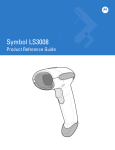
QuickScan® L
QD 2300 Bar Code Scanner
Product Reference Guide
Datalogic Scanning, Inc.
959 Terry Street
Eugene, Oregon 97402
Telephone: (541) 683-5700
Fax: (541) 345-7140
An Unpublished Work - All rights reserved. No part of the contents of this documentation or the procedures described
therein may be reproduced or transmitted in any form or by any means without prior written permission of Datalogic
Scanning, Inc. or its subsidiaries or affiliates ("Datalogic" or “Datalogic Scanning”). Owners of Datalogic products are
hereby granted a non-exclusive, revocable license to reproduce and transmit this documentation for the purchaser's
own internal business purposes. Purchaser shall not remove or alter any proprietary notices, including copyright
notices, contained in this documentation and shall ensure that all notices appear on any reproductions of the documentation.
Should future revisions of this manual be published, you can acquire printed versions by contacting your Datalogic representative. Electronic versions may either be downloadable from the Datalogic website (www.scanning.datalogic.com)
or provided on appropriate media. If you visit our website and would like to make comments or suggestions about this
or other Datalogic publications, please let us know via the "Contact Datalogic" page.
Disclaimer
Datalogic has taken reasonable measures to provide information in this manual that is complete and accurate, however, Datalogic reserves the right to change any specification at any time without prior notice.
Datalogic is a registered trademark of Datalogic S.p.A. in many countries and the Datalogic logo is a trademark of Datalogic S.p.A. All other brand and product names referred to herein may be trademarks of their respective owners.
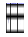
Table of Contents
Chapter 1. Introduction.............................................................................................................. 1
About this Guide .................................................................................................................... 1
Manual Overview ................................................................................................................... 1
Manual Conventions ............................................................................................................... 2
References ............................................................................................................................ 3
Technical Support .................................................................................................................. 3
Datalogic Website Support ................................................................................................. 3
Reseller Technical Support ................................................................................................. 3
Telephone Technical Support .............................................................................................. 3
Chapter 2. Getting Started ......................................................................................................... 5
About the Scanner ................................................................................................................. 5
Unpacking ............................................................................................................................. 5
Setting Up the Scanner ........................................................................................................... 6
Installing the Interface Cable ............................................................................................. 6
Removing the Interface Cable ............................................................................................ 7
Connecting Power (if required) ........................................................................................... 7
Configuring the Scanner .................................................................................................... 7
Chapter 3. Operation.................................................................................................................. 9
Nomenclature ........................................................................................................................ 9
LED and Beeper Indications ....................................................................................................10
Scan Mode ...........................................................................................................................11
Scanning .............................................................................................................................12
Aiming .................................................................................................................................12
Depth of Field .......................................................................................................................14
Maintenance .........................................................................................................................14
Chapter 4. Problem Isolation ................................................................................................... 15
Problem Isolation ..................................................................................................................15
Chapter 5. General Features..................................................................................................... 19
User Preferences ...................................................................................................................19
Scanning Sequence Examples .................................................................................................19
Errors While Scanning ...........................................................................................................19
User General Feature Defaults ................................................................................................20
Default Parameters ...............................................................................................................21
Restore Defaults ..............................................................................................................21
Beeper Tone .........................................................................................................................22
Beeper Volume .....................................................................................................................22
Power Mode .........................................................................................................................23
Scan Mode ...........................................................................................................................23
Stand Mode Timeout Period ..............................................................................................24
Scan Line Width ....................................................................................................................25
Laser On Time ......................................................................................................................25
Beep After Good Read ...........................................................................................................26
Transmit Label ID .................................................................................................................26
Prefix/Suffix Values ...............................................................................................................27
Global Prefix/Suffix ...............................................................................................................28
FN1 Substitution Values .........................................................................................................30
Transmit “No Read” Message ..................................................................................................30
Product Reference Guide
i
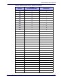
Chapter 6. RS-232 ................................................................................................................... 31
Introduction ......................................................................................................................... 31
Connecting an RS-232 Interface ............................................................................................. 32
RS-232 Parameter Defaults .................................................................................................... 33
RS-232 Host Parameters ....................................................................................................... 33
RS-232 Host Types ......................................................................................................... 36
Baud Rate ...................................................................................................................... 37
Parity ............................................................................................................................ 38
Stop Bit Select ................................................................................................................ 39
Data Bits (ASCII Format) ................................................................................................. 39
Check Receive Errors ....................................................................................................... 40
Hardware Handshaking .................................................................................................... 41
Software Handshaking ..................................................................................................... 43
Host Serial Response Time-out ......................................................................................... 45
RTS Line State ................................................................................................................ 46
Beep on <BEL> .............................................................................................................. 46
Intercharacter Delay ........................................................................................................ 47
Nixdorf Beep/LED Options ................................................................................................ 48
Ignore Unknown Characters ............................................................................................. 48
ASCII Character Set for RS-232 .............................................................................................. 49
Chapter 7. Keyboard Wedge Interface ..................................................................................... 55
Connecting a Keyboard Wedge Interface .................................................................................. 55
Keyboard Wedge Parameter Defaults ...................................................................................... 56
Keyboard Wedge Host Parameters .......................................................................................... 57
Keyboard Wedge Host Types ............................................................................................ 57
Keyboard Wedge Country Types (Country Codes) ................................................................ 58
Ignore Unknown Characters ............................................................................................. 59
Keystroke Delay ............................................................................................................. 60
Intra-Keystroke Delay ..................................................................................................... 60
Alternate Numeric Keypad Emulation ................................................................................. 61
Caps Lock On ................................................................................................................. 61
Caps Lock Override ......................................................................................................... 62
Convert Wedge Data ....................................................................................................... 62
Function Key Mapping ...................................................................................................... 63
FN1 Substitution ............................................................................................................. 63
Send Make and Break ...................................................................................................... 63
Keyboard Maps ............................................................................................................... 64
ASCII Character Set for Keyboard Wedge ................................................................................ 64
Chapter 8. USB Interface ......................................................................................................... 75
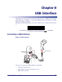
Connecting a USB Interface ................................................................................................... 75
USB Parameter Defaults ........................................................................................................ 76
USB Host Parameters ............................................................................................................ 77
USB Device Type ............................................................................................................ 77
USB Country Keyboard Types (Country Codes) ................................................................... 78
USB Keystroke Delay ....................................................................................................... 80
USB CAPS Lock Override .................................................................................................. 80
USB Ignore Unknown Characters ....................................................................................... 81
Emulate Keypad .............................................................................................................. 81
USB Keyboard FN 1 Substitution ....................................................................................... 82
Function Key Mapping ...................................................................................................... 82
Simulated Caps Lock ....................................................................................................... 83
Convert Case .................................................................................................................. 83
ASCII Character Set for USB .................................................................................................. 84
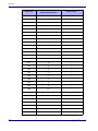
Chapter 9. Symbologies ........................................................................................................... 95
Introduction ......................................................................................................................... 95
Scanning Sequence Examples ................................................................................................ 95
ii
QuickScan® L
Errors While Scanning ...........................................................................................................95
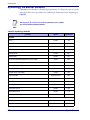
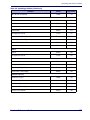
Symbology Parameter Defaults ...............................................................................................96
UPC/EAN ..............................................................................................................................99
Enable/Disable UPC-A/UPC-E ............................................................................................99
Enable/Disable UPC-E1 ................................................................................................... 100
Enable/Disable EAN-13/EAN-8 ......................................................................................... 101
Enable/Disable Bookland EAN .......................................................................................... 101
Decode UPC/EAN/JAN Supplementals ............................................................................... 102
UPC/EAN/JAN Supplemental Redundancy .......................................................................... 104
Transmit UPC-A Check Digit ............................................................................................ 104
Transmit UPC-E Check Digit ............................................................................................ 105
Transmit UPC-E1 Check Digit .......................................................................................... 105
UPC-A Preamble ............................................................................................................ 106
UPC-E Preamble ............................................................................................................ 107
UPC-E1 Preamble .......................................................................................................... 108
Convert UPC-E to UPC-A ................................................................................................. 109
Convert UPC-E1 to UPC-A ............................................................................................... 109
EAN-8/JAN-8 Extend ...................................................................................................... 110
UCC Coupon Extended Code ............................................................................................ 110
Code 128 ........................................................................................................................... 111
Enable/Disable Code 128 ................................................................................................ 111
Enable/Disable UCC/EAN-128 .......................................................................................... 111
Enable/Disable ISBT 128 ................................................................................................ 112
Code 39 ............................................................................................................................. 112
Enable/Disable Code 39 .................................................................................................. 112
Enable/Disable Trioptic Code 39 ...................................................................................... 113
Convert Code 39 to Code 32 ........................................................................................... 113
Code 32 Prefix .............................................................................................................. 114
Set Lengths for Code 39 ................................................................................................. 114
Code 39 Check Digit Verification ...................................................................................... 116
Transmit Code 39 Check Digit ......................................................................................... 116
Code 39 Full ASCII Conversion ........................................................................................ 117
Code 39 Buffering (Scan & Store) .................................................................................... 118
Code 93 ............................................................................................................................. 120
Enable/Disable Code 93 .................................................................................................. 120
Set Lengths for Code 93 ................................................................................................. 121
Code 11 ............................................................................................................................. 122
Set Lengths for Code 11 ................................................................................................. 123
Code 11 Check Digit Verification ...................................................................................... 125
Transmit Code 11 Check Digits ........................................................................................ 126
Interleaved 2 of 5 (ITF) ....................................................................................................... 126
Enable/Disable Interleaved 2 of 5 .................................................................................... 126
Set Lengths for Interleaved 2 of 5 .................................................................................... 127
I 2 of 5 Check Digit Verification ....................................................................................... 129
Transmit I 2 of 5 Check Digit .......................................................................................... 129
Convert I 2 of 5 to EAN-13 ............................................................................................. 130
Discrete 2 of 5 (DTF) ........................................................................................................... 130
Enable/Disable Discrete 2 of 5 ......................................................................................... 130
Set Lengths for Discrete 2 of 5 ........................................................................................ 131
Chinese 2 of 5 .................................................................................................................... 132
Enable/Disable Chinese 2 of 5 ......................................................................................... 132
Codabar (NW - 7) ............................................................................................................... 133
Enable/Disable Codabar .................................................................................................. 133
Set Lengths for Codabar ................................................................................................. 133
CLSI Editing ..................................................................................................................135
NOTIS Editing ............................................................................................................... 136
MSI ................................................................................................................................... 136
Enable/Disable MSI ........................................................................................................ 136
Set Lengths for MSI ....................................................................................................... 137
MSI Check Digits ........................................................................................................... 138
Product Reference Guide
iii
Transmit MSI Check Digit(s) ........................................................................................... 139
MSI Check Digit Algorithm .............................................................................................. 139
GS1 DataBar (RSS) ............................................................................................................ 140
Convert DataBar to UPC/EAN .......................................................................................... 141
Symbology - Specific Security Levels ..................................................................................... 142
Redundancy Level ......................................................................................................... 142
Security Level ............................................................................................................... 144
Symbology - Intercharacter Gap ........................................................................................... 146
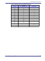
Appendix A. Technical Specifications ..................................................................................... 147
Standard Cable Pinouts ....................................................................................................... 149
Appendix B. Standard Defaults .............................................................................................. 151
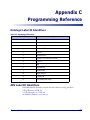
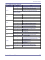
Appendix C. Programming Reference..................................................................................... 157
Datalogic Label ID Identifiers ............................................................................................... 157
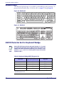
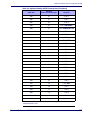
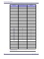
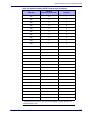
AIM Label ID Identifiers ....................................................................................................... 157
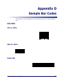
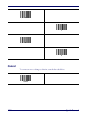
Appendix D. Sample Bar Codes .............................................................................................. 161
UPC/EAN ........................................................................................................................... 161
UPC-A, 100% ............................................................................................................... 161
EAN-13, 100% ............................................................................................................. 161
Code 128 .......................................................................................................................... 161
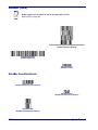
Code 39 ............................................................................................................................ 162
Code 93 ............................................................................................................................ 162
Code 11 ............................................................................................................................ 162
Interleaved 2 of 5 ............................................................................................................... 162
Discrete 2 of 5 (DTF) .......................................................................................................... 163
Chinese 2 of 5 .................................................................................................................... 163
Codabar ............................................................................................................................ 163
MSI .................................................................................................................................. 163
DataBar (RSS) ................................................................................................................... 164
DataBar Omnidirectional ................................................................................................ 164
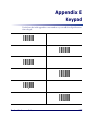
Appendix E. Keypad ............................................................................................................... 165
Cancel .............................................................................................................................. 166
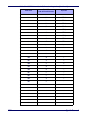
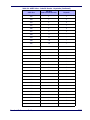
Appendix F. ASCII Character Sets.......................................................................................... 167
Appendix G. RS-232 Host Commands..................................................................................... 179
Index ..................................................................................................................... 181
iv
QuickScan® L
Chapter 1
Introduction
About this Guide
This manual presents advanced user information which includes connection, programming, maintenance, technical specifications, and other useful references. For additional
user information, see the Quick Reference Guide (QRG). Copies of other publications
for this product are downloadable free of charge from the website listed on the back cover
of this manual.
On leaving the factory, units are generally programmed for the most common terminal
and communications settings. If you need to change these settings, custom programming can be accomplished by scanning the bar codes in this guide.
Manual Overview
Chapter 1, Introduction provides a product overview, unpacking instructions, and cable
connection information.
Chapter 2, Getting Started presents information about unpacking and setting up the
scanner.
Chapter 3, Operation describes parts of the scanner, beeper and LED definitions, and
how to use the scanner in Trigger Single and Stand modes.
Chapter 4, Problem Isolation outlines troubleshooting procedures addressing various
problems.
Chapter 5, General Features includes programming bar codes for selecting common
features for the scanner and general use bar codes to customize how the data is transmitted to the host device.
Chapter 6, RS-232 supplies information about setting up the scanner for RS-232 operation.
Chapter 7, Keyboard Wedge Interface discusses how to set up the scanner for Keyboard
Wedge operation.
Chapter 8, USB Interface explains how to set up the scanner for USB operation.
Chapter 9, Symbologies defines options for all symbologies and provides the programming bar codes necessary for configuring these features.
Appendix A, Technical Specifications lists physical and performance characteristics, as
well as environmental and regulatory specifications. It also provides standard cable pinouts.
Appendix B, Standard Defaults references common factory default settings for scanner
features and options.
Product Reference Guide
1
Introduction
Appendix C, Programming Reference is a listing of AIM code identifiers, ASCII character conversions and keyboard maps.
Appendix D, Sample Bar Codes offers sample bar codes of several common symbologies.
Appendix E, Keypad includes numeric bar codes to be scanned for certain parameter settings.
Appendix F, ASCII Character Sets provides ASCII character value tables.
Appendix G, RS-232 Host Commands lists host commands the scanner will respond to
when in RS-232 interface mode.
Manual Conventions
The following conventions are used in this document:
Italics are used to highlight the following:
•
Chapters and sections in this and related documents
•
Dialog box, window and screen names
•
Bold
•
Drop-down list and list box names.
text is used to highlight the following:
Key names on a keypad.
Bullets (•) indicate:
•
Action items
•
Lists of alternatives
•
Lists of required steps that are not necessarily sequential
Sequential lists (e.g., those that describe step-by-step procedures) appear as numbered
lists.
Throughout the programming bar code menus, asterisks (*) are used to denote default
parameter settings.
* Indicates
2
*Baud Rate 9600
Feature/Option
QuickScan® L
References
The symbols listed below are used in this manual to notify the reader of key issues or
procedures that must be observed when using the scanner:
Notes contain information necessary for properly diagnosing, repairing and operating the scanner.
NOTE
The CAUTION symbol advises you of actions that could damage
equipment or property.
CAUTION
References
Current versions of the Product Reference Guide (PRG), Quick Reference Guide
(QRG), and any other manuals and instruction sheets for this product can be downloaded from the website listed on the back cover of this manual. Alternatively, printed copies
or product support CDs can be purchased through your Datalogic reseller.
Technical Support
Datalogic Website Support
The Datalogic website (www.scanning.datalogic.com) is the complete source for technical
support and information for Datalogic products. The site offers product support, product registration, warranty information, product manuals, product tech notes, software
updates, demos, and instructions for returning products for repair.
Reseller Technical Support
An excellent source for technical assistance and information is an authorized Datalogic
reseller. A reseller is acquainted with specific types of businesses, application software,
and computer systems and can provide individualized assistance.
Telephone Technical Support
If you do not have internet or email access, you may contact Datalogic technical support
at (541) 349-8283 or check the back cover of your manual for more contact information.
Product Reference Guide
3
Introduction
NOTES
4
QuickScan® L
Chapter 2
Getting Started
About the Scanner
The scanner combines excellent scanning performance and advanced ergonomics to provide the
best value in a lightweight laser scanner. Whether used in Trigger Single or Stand mode, the
scanner ensures comfort and ease of use for extended periods of time.
This scanner does not support PDF417 bar codes and its variants.
NOTE
This scanner supports the following interfaces:
•
Keyboard Wedge connection to a host. The host interprets scanned data as keystrokes.
This interface supports the following international keyboards (for Windows® environment): North America, German, French, French Canadian, Spanish, Italian, Swedish, UK
English, Portuguese-Brazilian, and Japanese.
•
Standard RS-232 connection to a host. Scan bar code menus to set up proper communication of the scanner with the host.
The scanner uses TTL RS-232 signal levels, which will interface with most
system architectures.
NOTE
•
USB connection to a host. The scanner autodetects a USB host and defaults to the HID
keyboard interface type. Select other USB interface types by scanning programming bar
code menus.This interface supports the following international keyboards (for Windows® environment): North America, German, French, French Canadian, Spanish, Italian, Swedish, UK English, Portuguese-Brazilian, and Japanese.
Unpacking
Verify that the scanner and any accessories are what were ordered and that they are undamaged.
If any damage occurred in transit, contact Technical Support on page 3.
KEEP THE PACKAGING. Should the unit ever require service, it should be returned in its
original shipping container.
Product Reference Guide
5
Getting Started
Setting Up the Scanner
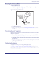
Installing the Interface Cable
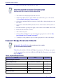
To connect the interface cable:
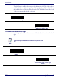
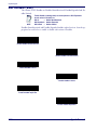
1. Insert the interface cable’s modular connector clip into the cable interface port on the bottom of the scanner handle. (See Figure 1).
2. Gently tug the cable to ensure the connector is properly secured.
3. Connect the other end of the interface cable to the host. (See the specific host chapter for
information on host connections.)
Figure 1. Connecting the Interface Cable
Bottom of Scanner
Cable
Interface Cable Port
Cable Strain Relief
To Host
NOTE
6
Cable Clip (Latch)
Specific cables are required for connection to different hosts. The
connectors illustrated in each host chapter are examples only. Actual
connectors may vary from those illustrated, but the steps to connect
the scanner remain the same.
QuickScan® L
Setting Up the Scanner
Removing the Interface Cable
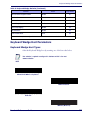
To remove the Interface Cable:
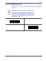
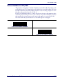
1. Unlatch the installed cable modular connector by depressing the connector clip with the
end of a paper clip as shown in Figure 2.
Figure 2. Releasing the Cable Latch
Insert a paperclip
into this hole to
release the
cable latch
Strain Relief
Cable
2. Carefully slide out the cable.
3. Follow the steps in the previous section, Installing the Interface Cable, to connect a
new cable.
Connecting Power (if required)
If the host does not provide power to the scanner, an external power connection to the scanner is
required. To connect power:
1. Connect the interface cable to the bottom of the scanner, as previously described in the
section, Installing the Interface Cable.
2. Connect the other end of the interface cable to the host (refer to the host manual to locate
the correct port).
3. Plug the power supply into the power jack on the interface cable. Plug the other end of the
power supply into an AC outlet.
Configuring the Scanner
To configure the scanner, use the bar codes included in this manual.
See Chapter 5, General Features and Chapter 9, Symbologies for information about
programming the scanner using bar code menus. Also see each host-specific chapter to set up a
connection to a specific host type.
Product Reference Guide
7
Getting Started
NOTES
8
QuickScan® L
Chapter 3
Operation
This chapter provides beeper and LED definitions, techniques involved in scanning bar codes,
general instructions and tips about scanning, and decode zone diagrams.
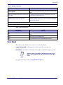
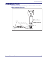
Nomenclature
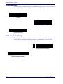
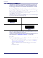
Nomenclature for physical features on the scanner is shown in Figure 3.
Figure 3. Nomenclature
LED
Scan
Window
Trigger
Product Reference Guide
9
Operation
LED and Beeper Indications
The scanner’s beeper sounds and its two-color LED illuminates to indicate various functions or
errors on the scanner. The tables below list these indications. One exception to the behaviors
listed in the tables is that the scanner’s functions are programmable, and may or may not be
turned on. For example, certain indications, such as the power-up beep can be disabled using
programming bar code labels.
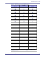
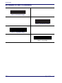
Table 1. Beeper Functions
Beeper Sequence
Indication
Standard Use
Low/medium/high beeps
Power up.
Short high beeps
A bar code label was decoded (if decode beeper is enabled).
4 long low beeps
A transmission error was detected in a scanned bar code. The data is
ignored. This occurs if a unit is not properly configured. Check option
setting.
5 low beeps
Conversion or format error.
Low/high/low beeps
Advanced Data Formatting (ADF) transmit error. (For information about
ADF programming, refer to Technical Support.)
High/high/high/low beeps
RS-232 receive error.
Parameter Menu Scanning
Short high beeps
Correct entry scanned or correct menu sequence performed.
Low/high beeps
Input error, incorrect bar code or “Cancel” scanned, wrong entry, incorrect bar code programming sequence; remain in Programming Mode.
High/low beeps
Keyboard parameter selected. Enter value using bar code keypad.
High/low/high/low beeps
Successful program exit with change in the parameter setting.
Low/high/low/high beeps
Out of host parameter storage space. Scan Default Parameters on
page 21.
Code 39 Buffering
High/low beeps
New Code 39 data was entered into the buffer.
3 Beeps - long high beeps
Code 39 buffer is full.
Low/high/low beeps
The Code 39 buffer was erased or there was an attempt to clear or
transmit an empty buffer.
Low/high beeps
A successful transmission of buffered data.
Host Specific
USB Only
10
QuickScan® L
Scan Mode
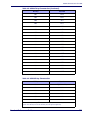
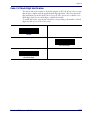
Table 1. Beeper Functions
Beeper Sequence
Indication
4 short high beeps
Scanner has not completed initialization. Wait several seconds and scan
again.
Scanner gives a power-up beep after scanning a USB
Device Type.
Communication with the bus must be established before the scanner
can operate at the highest power level.
This power-up beep occurs more than once.
The USB bus may put the scanner in a state where power to the scanner
is cycled on and off more than once. This is normal and usually happens
when the host cold boots.
RS-232 Only
1 short high beep
A <BEL> character is received and Beep on <BEL> is enabled.
Table 2. LED Indications
LED Sequence
Indication
Off
No power is applied to the scanner, or the scanner is on and ready to
scan.
Green
A bar code was successfully decoded.
Red
A data transmission error or scanner malfunction occurred.
Scan Mode
The scanner can be configured to be active in one of two Scan Modes:
Trigger Single Mode — the trigger button must be pressed to scan a bar code.
Stand Mode — the scanner continuously reads regardless of whether the trigger is pressed
When the scanner is not used for an extended period of time in Stand
Mode, it enters Sleep Mode. To wake the scanner, press the trigger
button.
NOTE
To toggle between these modes, see Scan Mode on page 23.
Product Reference Guide
11
Operation
Scanning
To scan a bar code:
1. Install and program the scanner (See “Setting Up the Scanner” on page 6.). For
assistance, contact Technical Support.
2. Ensure all connections are secure. (See the host chapter for the scanner.)
3. Aim the scanner at the bar code.
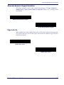
4. If the scanner is in Trigger Single Mode, press the trigger button. (In Stand Mode, no trigger button press is required. The scanner laser is in constant ON mode.)
Figure 4. Scanning With/Without the Trigger
Trigger Single Mode Stand Mode
Push Trigger to
initiate scan.
Trigger push
not required.
5. Upon successful decode, the scanner beeps and the LED flashes green. (For more information about beeper and LED definitions, see Table 1 and Table 2.)
The width of the scan line is dependent upon the current setting for
the programmable feature, Scan Line Width. “Full” (the default setting) or “Medium” scan line widths are available.
NOTE
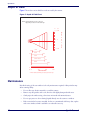
Aiming
For a typical, full-sized UPC label, the scanner should be held between 1” and 7” from the bar
code. Ensure that the scan line crosses the entire bar code as shown in Figure 5.
Figure 5. Correct and Incorrect Aiming
012345
012345
The scan line is smaller when the scanner is closer to the bar code and grows when the scanner is
drawn away from the bar code. For best results, hold the scanner closer to bar codes with very
small bars or elements (mil size) and pull the scanner further away from labels having larger bars
or elements (mil size).
12
QuickScan® L
Aiming
Do not hold the scanner perpendicular to the bar code when scanning. Laser light reflecting
directly back into the scanner from the bar code can result in specular reflection, which can in
turn cause difficulties with decoding. Tilt the scanner to avoid the dead zone (indicated by an
‘X’ in Figure 6) up to 65 degrees upwards or downwards.
Figure 6. Aiming to Avoid the Dead Zone
65°
65°
Product Reference Guide
13
Operation
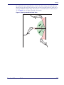
Depth of Field
Figure 7 shows the zone in which bar codes are read by the scanner.
Figure 7. Depth of Field Chart
NOTE: Typical performance at 73° F (23°C) on
high quality bar codes in normal room light.
in.
cm
6
15.24
W
I
D
T
H
0
0
O
F
F
I
E
L
D
6
0.4"
0.1"
5 mil
7.5 mil
7.8"
10 mil
13 mil
*
in. 0
cm 0
15.24
5.5"
8.6"
100% UPC
9.1"
20 mil
10.6"
5
12.7
10
25.4
15
38.1
DEPTH OF FIELD
* Minimum distance determined by bar code length and scan angle
Maintenance
Periodic cleaning of the scan window is the only maintenance required. A dirty window may
affect scanning ability.
14
•
Do not allow any abrasive material to touch the scanner.
•
Remove any dirt particles with a soft, lint-free cloth lightly dampened with water.
•
Gently wipe the window using a lens tissue moistened with ammonia/water.
•
Do not spray water or other cleaning liquids directly onto the scanner or window.
•
If the scan window becomes scratched, broken or contaminated with heavy dust, replace
with a new window, which is available as an orderable accessory.
QuickScan® L
Chapter 4
Problem Isolation
This chapter provides troubleshooting information, technical specifications, and signal descriptions (pinouts).
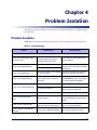
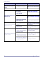
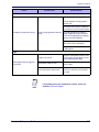
Problem Isolation
Table 3 provides problem/remedy information for use in troubleshooting scanner functions.
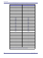
Table 3. Troubleshooting
Problem
Possible Causes
Possible Solutions
Beeper Indications (Also see LED and Beeper Indications on page 10)
Scanner emits frequent beeps. (USB
host interface only.)
The USB bus may put the scanner in a
state where power to the scanner is
cycled on and off more than once.
ADF transmit error.
This is normal and usually happens when
the host cold boots.
Invalid ADF rule is detected.
Refer to the Advanced Data Formatting Programmer’s Guide for information about ADF
programming.
Scanner emits low/high beeps.
Input error, incorrect bar code or Cancel
bar code was scanned.
Scan the correct numeric bar codes within
range for the parameter programmed.
Scanner emits low/high/low beeps.
The Code 39 buffer was erased or there
was an attempt to clear or transmit an
empty buffer.
Normal when scanning the Code 39 Buffering Clear Buffer bar code or upon attempt
to transmit an empty Code 39 buffer.
Out of host parameter storage space.
Scan Default Parameters on page 21.
Out of memory for ADF rules.
Reduce the number of ADF rules or the
number of steps in the ADF rules.
Scanner emits high/low beeps.
The scanner is buffering Code 39 data.
Normal.
Scanner emits high/high/high/low
beeps.
RS-232 receive error.
Normal during host reset. Otherwise, set the
scanner's RS-232 parity to match the host
setting.
Scanner emits four long low beeps.
A transmission error was detected in a
scanned bar code. The data is ignored.
This occurs if a unit is not properly configured. Verify programmed options.
Scanner emits four short high beeps
(USB only).
Scanner has not completed initialization.
Wait several seconds and scan again.
Scanner emits low/high/low beeps.
Scanner emits low/high/low/high beeps.
Product Reference Guide
15
Problem Isolation
Problem
Scanner emits a short low/high/low/high
beep sequence while it is being programmed.
Possible Causes
Possible Solutions
Out of ADF parameter storage space.
Erase all rules and re-program with shorter
rules.
Scanner is not programmed for the correct bar code type.
Program the scanner to read that type of bar
code. See Chapter 9, Symbologies.
Bar code is unreadable.
Scan other samples of the same bar code
type to determine if the bar code is defaced.
Distance between scanner and bar code
is incorrect.
Move the scanner closer to or further from
the bar code. See Depth of Field on page
14.
The scan line is not crossing every bar
and space of the bar code.
Move the bar code until the scan line is
within the acceptable aiming pattern. See
Figure 5.
Scanner is not programmed for the correct host type.
Scan the appropriate host type programming bar code. See the chapter corresponding to the host type.
Interface cable is loose.
Check for loose cable connection and reconnect cable.
Decoding Bar Codes
Scanner emits laser light, but does not
decode the bar code.
Scanner decodes bar code, but does not
transmit the data to the host.
Conversion or format error was detected.
The scanner’s conversion parameters
are not properly configured.
Ensure the scanner’s conversion parameters are properly configured.
Conversion or format error was detected.
Scanner emits five long low beeps after
a bar code is decoded.
An ADF rule was set up with characters
that can't be sent for the host selected.
Change the ADF rule, or change to a host
that can support the ADF rule.
Conversion or format error was detected.
A bar code was scanned with characters
that can't be sent for that host.
16
Change the bar code, or change to a host
that can support the bar code.
QuickScan® L
Problem Isolation
Problem
Possible Causes
Possible Solutions
Host Error
Ensure the proper host is selected.
Scan the appropriate host type programming bar code.
For RS-232, set the scanner's communication parameters to match the host's settings.
Host displays scanned data incorrectly.
Scanner is not programmed to work with
the host.
For a USB HID keyboard or Keyboard
Wedge configuration, program the system
for the correct keyboard type and language,
and turn off the CAPS LOCK key.
Program the proper editing options (e.g.,
ADF, UPC-E to UPC-A Conversion).
Check the scanner’s host type parameters
or editing options.
Trigger
Nothing happens when the trigger button is pressed.
NOTE
Product Reference Guide
No power to the scanner.
Verify that system power is sufficient. If the
scanner requires a power supply, reconnect
using an approved power supply.
Interface/power cables are loose.
Check for loose cable connections and reconnect cables.
Incorrect host interface cable is used.
Verify that the correct host interface cable is
used. If not, connect the correct host interface cable.
If the problem persists after performing these checks, contact your
distributor or Technical Support.
17
Problem Isolation
NOTES
18
QuickScan® L
Chapter 5
General Features
User Preferences
User preferences for the general features listed in this chapter can be selected using the
programming bar codes that accompany each feature description. To set feature values,
scan a single programming bar code or a short bar code sequence as instructed for each
feature. The settings are stored in non-volatile memory and are preserved even when the
scanner is powered down.
Typically, a scanner ships with the settings shown in User General Feature Defaults
on page 20 (also see Appendix B, Standard Defaults for all host defaults). If the default values suit requirements, programming may not be necessary.
If not using a USB cable, select a host type (see each host chapter for specific host information) after the power-up beeps sound. This is only necessary upon the first power-up
when connecting to a new host.
To return all features to their default values, reference the topic, Return to Factory Defaults. Throughout the programming bar code menus, default values are indicated with
asterisks (*).
* Indicates Default
*High Frequency
Feature/Option
Scanning Sequence Examples
In most cases, scanning one bar code sets the parameter value. For example, to set the
beeper tone to high, scan the High Frequency (beeper tone) bar code on page 19. The
scanner issues a fast warble beep and the LED turns green, signifying a successful parameter entry.
Other parameters, such as Serial Response Time-Out or Data Transmission Formats, require the scanning of a sequence of bar codes. See these parameter descriptions for this
procedure.
Errors While Scanning
Unless otherwise specified, when an error is made during a scanning sequence, just rescan the correct feature bar code(s).
Product Reference Guide
19
General Features
User General Feature Defaults
Table 4 lists the factory defaults for the general features described in this chapter, plus
provides a place for you to log any special requirements or user-preferred settings at your
installation. To change any option, scan the appropriate programming bar code(s) provided in this chapter.
See Appendix B, Standard Defaults for a listing of all programmable
features.
NOTE
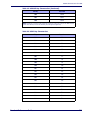
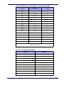
Table 4. General Feature Defaults
General Feature
20
Standard Factory
Default
Page Number
Beeper Tone
Medium
22
Beeper Volume
High
22
Power Mode
Continuous On
23
Scanning Mode
Trigger Single
23
Scan Line Width
Full Width
25
Laser On Time
3.0 Sec
25
Beep After Good Decode
Enable
26
Transmit Label ID Character
None
26
Prefix Value
7013 <CR><LF>
27
Suffix Value
7013 <CR><LF>
27
Scan Data Transmission Format
Data as is
26
FN1 Substitution Values
Set
30
Transmit “No Read” Message
Disable
30
Record Your Setting
QuickScan® L
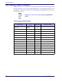
Default Parameters
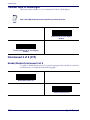
Default Parameters
The scanner can be reset using one of two default settings: factory defaults or custom defaults. Scan the appropriate bar code(s) below to reset the scanner to its default settings
and/or set the scanner’s current settings as the custom default.
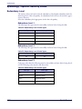
Scan the Set Factory Defaults bar code below to eliminate all
custom default values and return the scanner to factory default values. (For factory default values, see Appendix B, Standard Defaults.)
Set Factory Defaults —
Write to Custom Defaults — Custom default parameters can be configured to set
unique default values for all parameters. After changing all parameters to the desired default values, scan the Write to Custom Defaults bar code below to configure custom defaults.
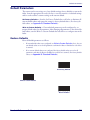
Restore Defaults
Resets all default parameters as follows:
•
If custom default values were configured (see Write to Custom Defaults above), the custom default values are set for all parameters each time the Restore Defaults bar code below
is scanned.
•
If no custom default values were configured, the factory default values are set for all
parameters each time the Restore Defaults bar code below is scanned. (For factory default
values, see Appendix B, Standard Defaults.)
Set Factory Defaults
Write to Custom Defaults
*Restore Defaults
Product Reference Guide
21
General Features
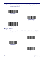
Beeper Tone
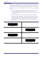
To select a decode beep frequency (tone), scan the Low Frequency, Medium Frequency,
or High Frequency bar code.
Low Frequency
*Medium Frequency
(Optimum Settings)
High Frequency
Beeper Volume
To select a beeper volume, scan the Low Volume, Medium Volume, or High Volume
bar code.
Low Volume
Medium Volume
*High Volume
22
QuickScan® L
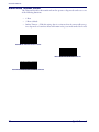
Power Mode
Power Mode
This parameter determines whether or not power remains on after a decode attempt.
When in reduced power mode, the scanner enters low power consumption mode after
each decode. When in continuous power mode, power remains on after each decode.
*Continuous On
Reduced Power Mode
Scan Mode
This parameter determines whether the scanner is in Trigger Single Mode or Stand Mode.
In Trigger Single Mode, the scanner trigger button must be pressed to decode each
scanned bar code. In Stand Mode, the scanner laser is in constant ON state and no trigger
button press is required to scan a bar code.
Depending upon which mode the scanner currently is in, scan the “Toggle Scan Mode”
to switch from Trigger Single to Stand Mode, or from Stand Mode to Trigger Single Mode.
The standard default setting for this feature is Trigger Single Mode.
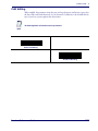
While in the Stand Mode of operation, if the scanner has not been used for several minutes it will shift to low power operation, signalled by a narrowing of the scanning beam.
When in low power mode, the scanner will respond to a barcode and come back to normal Stand Mode operation upon seeing/reading the label.
If the scanner has been idle for an extended configurable period1, it will timeout, then
enter sleep mode with the scanning beam turned off. To wake the scanner from sleep
mode, press the trigger button.
*Toggle Scan Mode
1. See the following topic Stand Mode Timeout Period.
Product Reference Guide
23
General Features
Stand Mode Timeout Period
The Timeout Period for the transition from low power to sleep mode can be set to one
of the following durations:
•
1 Hour
•
5 Hours (default)
•
Infinite Timeout — With this setting, there is no timeout, thus the scanner will never go
into sleep mode or beam shut-off but will remain in low power mode until a label is read.
Stand Mode Timeout Period = 1 Hour
*Stand Mode Timeout Period = 5 Hours
Stand Mode Timeout Period = Infinite Timeout
24
QuickScan® L
Scan Line Width
Scan Line Width
Scan a bar code below to set the scan line width. A full scan line width is the default. The
medium scan line width is useful for scanning menus or pick-lists.
This feature applies to scanners in Trigger Single Mode only.
NOTE
*Full Width
Medium Width
Laser On Time
This parameter sets the maximum time that decode processing continues during a scan
attempt. It is programmable in 0.1 second increments from 0.5 to 9.9 seconds. The default Laser On Time is 3.0 seconds.
To set a Laser On Time, scan the bar code below. Next, scan the two numeric bar codes
from Appendix E, Keypad, that correspond to the desired On Time. Single digit numbers must be padded with a leading zero. For example, to set an On Time of 0.5 seconds,
scan the bar code below, then scan the “0” and “5” bar codes. If an error is made, or the
selection needs to be changed, scan Cancel on page 166.
This feature applies to scanners in Trigger Single Mode only.
NOTE
Laser On Time
Product Reference Guide
25
General Features
Beep After Good Read
Scan a bar code below to select whether or not the scanner should beep after a good read.
If Do Not Beep After Good Read is selected, the beeper still operates during parameter
menu scanning and indicates error conditions.
*Beep After Good Read
(Enable)
Do Not Beep After Good Read
(Disable)
Transmit Label ID
Label ID characters identify the code (symbology) type of a scanned bar code. This may
be useful when the scanner is decoding more than one code type. In addition to any single character prefix already selected, the Label ID character is inserted between the prefix
and the decoded bar code.
Select no Label ID character, a Datalogic Label ID, or an AIM Label ID. For a listing of
Label ID Characters, see Datalogic Label ID Identifiers on page 157 and AIM Label ID Identifiers on page 157.
Datalogic Label ID
AIM Label ID
*No Label ID
26
QuickScan® L
Prefix/Suffix Values
Prefix/Suffix Values
A prefix and/or suffix can be appended to scan data for use in data editing as described
in the feature description, Global Prefix/Suffix on page 28.
To set a value for a prefix or suffix:
1. Change the scan data format using the instructions in the feature description, Global
Prefix/Suffix on page 28.
2. Scan the appropriate prefix/suffix bar code below.
3. Scan a four-digit number (i.e., four bar codes from Appendix E, Keypad) that corresponds to that value.
NOTE
When using host commands to set the prefix or suffix, set the key
category parameter to 1, then set the 3-digit decimal value corresponding to the desired keystroke as listed in Table 34 on page 167
(results in a four-digit ASCII code).
4. To correct an error or change a selection, scan Data Format Cancel on page 29.
Set Prefix
Set Suffix
Product Reference Guide
27
General Features
Global Prefix/Suffix
ASCII characters may be added as a prefix (in a position before the bar code data) and/
or as a suffix (in a position following the bar code data). Scan the bar code below labeled
“Scan Options”, then one of the following four bar codes corresponding to the position(s) you wish to specify:
•
Data As Is
•
<DATA> <SUFFIX>
•
<PREFIX> <DATA>
•
<PREFIX> <DATA> <SUFFIX>.
Scan the “Enter” bar code to complete the change. To set values for the prefix and/or
suffix, See Prefix/Suffix Values on page 27. Scan the bar code “Data Format Cancel” if you wish to cancel the change.
If a carriage return/enter is required after each scanned bar code, scan the following bar
codes in order:
1. “Scan Options”
2. <DATA> <SUFFIX>
3. “Enter”
Scan Options
*Data As Is
<DATA> <SUFFIX>
28
QuickScan® L
Global Prefix/Suffix
Global Prefix/Suffix — continued
<PREFIX> <DATA>
<PREFIX> <DATA> <SUFFIX>
Enter
Data Format Cancel
Product Reference Guide
29
General Features
FN1 Substitution Values
The Wedge and USB HID Keyboard hosts support an FN1 substitution feature. When
enabled, any FN1 character (0x1b) in an EAN128 bar code is substituted with a value.
This value defaults to 7013 (Enter Key).
To select an FN1 substitution value via bar code menus:
1. Scan the bar code below.
*Set FN1 Substitution Value
2. Look up the keystroke desired for FN1 Substitution inAppendix F, ASCII Character
Sets for the currently installed host interface.
3. Enter the 4-digit substitution value by scanning each digit in Appendix E, Keypad.
To correct an error or change the selection, scan Cancel.
To enable FN1 substitution for keyboard wedge, scan the Enable FN1 Substitution
on page 63.
To enable FN1 Substitution for USB HID keyboard, scan the Enable FN1 Substitution on page 82.
Transmit “No Read” Message
Scan a bar code below to select whether or not to transmit a No Read message. When
enabled, the characters NR are transmitted when a bar code is not decoded. When disabled, if a bar code does not decode, nothing is sent to the host.
Enable No Read
*Disable No Read
30
QuickScan® L
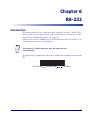
Chapter 6
RS-232
Introduction
This chapter describes how to set up the scanner with an RS-232 host. The RS-232 interface is used to connect the scanner to point-of-sale devices, host computers, or other
devices with an available RS-232 port (e.g., com port).
If the host is not listed in Table 6, refer to the documentation for the host device to set
communication parameters to match the host.
The scanner uses TTL RS-232 signal levels, which will interface with most
system architectures.
NOTE
Throughout the programming bar code menus, default values are indicated with asterisks
(*).
* Indicates Default
Product Reference Guide
*Baud Rate 57,600
Feature/Option
31
RS-232
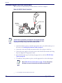
Connecting an RS-232 Interface
This connection is made directly from the scanner to the host computer.
Figure 8. RS-232 Direct Connection
Interface Cable
Serial Port
Connector
to Host
Power
Supply Cable
Interface cables vary depending on configuration. The connectors illustrated
in Figure 8 are examples only. The connectors may be different than those
illustrated, but the steps to connect the scanner remain the same.
NOTE
1. Attach the modular connector of the RS-232 interface cable to the cable interface port on
the scanner (see Installing the Interface Cable on page 6).
2. Connect the other end of the RS-232 interface cable to the serial port on the host.
3. Connect the power supply1 to the serial connector end of the RS-232 interface cable. Plug
the power supply into an appropriate outlet.
4. Select the RS-232 host type by scanning the appropriate bar code from RS-232 Host
Types on page 36.
5. To modify any other parameter options, scan the appropriate bar codes in this chapter.
Refer to RS-232 Host Commands on page 179 for a listing of host
commands the scanner will respond to when in RS-232 interface mode.
NOTE
1. Use only aDatalogic power supply approved for this product.
32
QuickScan® L
RS-232 Parameter Defaults
RS-232 Parameter Defaults
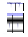
Table 5 lists the defaults for RS-232 host parameters. If any option needs to be changed,
scan the appropriate bar code(s) provided in the Parameter Descriptions section beginning on page 33.
See Appendix B, Standard Defaults for all user preferences, hosts, symbologies, and miscellaneous default parameters.
NOTE
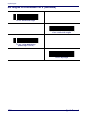
Table 5. RS-232 Defaults
Parameter
Default
Page Number
RS-232 Host Parameters
RS-232 Host Types
Standard
36
Baud Rate
9600
37
Parity Type
None
38
Stop Bit Select
1 Stop Bit
39
Data Bits (ASCII Format)
8-Bit
39
Check Receive Errors
Enable
40
Hardware Handshaking
None
42
Software Handshaking
None
44
Host Serial Response Time-out
2 Sec
45
RTS Line State
Low RTS
46
Beep on <BEL>
Disable
46
Intercharacter Delay
0 msec
47
Nixdorf Beep/LED Options
Normal Operation
48
Ignore Unknown Characters
Send Bar Code
48
RS-232 Host Parameters
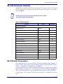
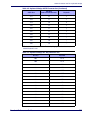
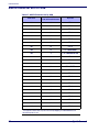
Various RS-232 hosts are set up with their own parameter default settings (Table 6). Selecting the ICL, Fujitsu, Wincor-Nixdorf Mode A, Wincor-Nixdorf Mode B, Olivetti,
Omron, or terminal sets the defaults listed in Table 6.
Selecting the ICL, Fujitsu, Wincor-Nixdorf Mode A, Wincor-Nixdorf Mode B, OPOS
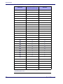
terminal enables the transmission of code ID characters listed in Table 7 on page 34.
These code ID characters are not programmable and are separate from the Transmit
Code ID feature. The Transmit Code ID feature should not be enabled for these terminals.
Product Reference Guide
33
RS-232
Table 6. Terminal Specific RS-232
Fujitsu
WincorNixdorf
Mode A
WincorNixdorf
Mode B/
OPOS
Olivetti
Omron
Yes
Yes
Yes
Yes
Yes
Yes
Data as is
Data/Suffix
Data/Suffix
Data/Suffix
Data/Suffix
Prefix/Data/Suffix
Data/Suffix
Suffix
CR/LF
(7013)
CR (1013)
CR (1013)
CR (1013)
CR (1013)
ETX (1002)
CR (1013)
Baud Rate
9600
9600
9600
9600
9600
9600
9600
Parity
None
Even
None
Odd
Odd
Even
None
Hardware Handshaking
None
RTS/CTS
Option 3
None
RTS/CTS
Option 3
RTS/CTS
Option 3
None
None
Software Handshaking
None
None
None
None
None
Ack/Nak
None
Serial Response
Time-out
2 Sec.
9.9 Sec.
2 Sec.
9.9 Sec.
9.9 Sec.
9.9 Sec.
9.9 Sec.
Stop Bit
Select
One
One
One
One
One
One
One
ASCII Format
8-Bit
8-Bit
8-Bit
8-Bit
8-Bit
7-Bit
8-Bit
Beep On
<BEL>
Disable
Disable
Disable
Disable
Disable
Disable
Disable
RTS Line
State
Low
High
Low
Low
Low = No data
to send
Low
High
Prefix
None
None
None
None
None
STX (1003)
None
Parameter
Transmit
Code ID
Data Transmission Format
Standard
(Default)
ICL
No
*In the Nixdorf Mode B, if CTS is Low, scanning is disabled. When CTS is High, the user can scan bar codes.
**If Nixdorf Mode B is scanned without the scanner connected to the proper host, it may appear unable to scan. If this happens, scan a
different RS-232 host type within 5 seconds of cycling power to the scanner.
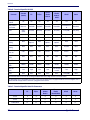
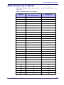
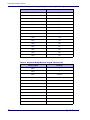
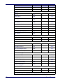
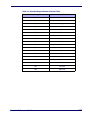
Table 7. Terminal Specific Code ID Characters
34
ICL
Fujitsu
WincorNixdorf
Mode A
WincorNixdorf
Mode B/OPOS
Olivetti
Omron
UPC-A
A
A
A
A
A
A
UPC-E
E
E
C
C
C
E
EAN-8/JAN-8
FF
FF
B
B
B
FF
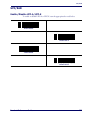
QuickScan® L
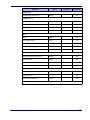
RS-232 Host Parameters
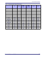
Table 7. Terminal Specific Code ID Characters
ICL
Fujitsu
WincorNixdorf
Mode A
WincorNixdorf
Mode B/OPOS
Olivetti
Omron
EAN-13/JAN-13
F
F
A
A
A
F
Code 39
C <len>
None
M
M
M <len>
C <len>
Codabar
N <len>
None
N
N
N <len>
N <len>
Code 128
L <len>
None
K
K
K <len>
L <len>
I 2 of 5
I <len>
None
I
I
I <len>
I <len>
Code 93
None
None
L
L
L <len>
None
D 2 of 5
H <len>
None
H
H
H <len>
H <len>
UCC/EAN 128
L <len>
None
P
P
P <len>
L <len>
MSI
None
None
O
O
O <len>
None
Bookland EAN
F
F
A
A
A
F
Trioptic
None
None
None
None
None
None
Code 11
None
None
None
None
None
None
IATA
H<len>
None
H
H
None
None
Code 32
None
None
None
None
None
None
Product Reference Guide
35
RS-232
RS-232 Host Types
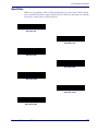
To select an RS-232 host interface, scan one of the following bar codes.
*Standard RS-232
ICL RS-232
RS-232 Wincor-Nixdorf Mode A
RS-232 Wincor-Nixdorf Mode B
RS-232 Olivetti ORS4500
RS-232 Omron
RS-232 OPOS
RS-232 Fujitsu
36
QuickScan® L
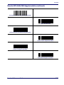
RS-232 Host Parameters
Baud Rate
Baud rate is the number of bits of data transmitted per second. Set the scanner's baud
rate to match the baud rate setting of the host device. Otherwise, data may not reach the
host device or may reach it in distorted form.
Baud Rate 600
Baud Rate 1200
Baud Rate 2400
Baud Rate 4800
*Baud Rate 9600
Baud Rate 19,200
Baud Rate 38,400
Product Reference Guide
37
RS-232
Parity
A parity check bit is the most significant bit of each ASCII coded character. Select the
parity type according to host device requirements.
•
Select Odd parity and the parity bit value is set to 0 or 1, based on data, to ensure that an
odd number of 1 bits are contained in the coded character.
•
Select Even parity and the parity bit value is set to 0 or 1, based on data, to ensure that an
even number of 1 bits are contained in the coded character.
•
Select Mark parity and the parity bit is always 1.
•
Select Space parity and the parity bit is always 0.
•
Select None when no parity bit is required.
Odd
Even
Mark
Space
*None
38
QuickScan® L
RS-232 Host Parameters
Stop Bit Select
The stop bit(s) at the end of each transmitted character marks the end of transmission of
one character and prepares the receiving device for the next character in the serial data
stream. The number of stop bits selected (one or two) depends on the number the receiving terminal is programmed to accommodate. Set the number of stop bits to match host
device requirements.
*1 Stop Bit
2 Stop Bits
Data Bits (ASCII Format)
This parameter allows the scanner to interface with devices requiring a 7-bit or 8-bit
ASCII protocol.
7-Bit
*8-Bit
Product Reference Guide
39
RS-232
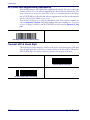
Check Receive Errors
Select whether or not the parity, framing, and overrun of received characters are checked.
The parity value of received characters is verified against the parity parameter selected
above.
*Check For Received Errors
(Enable)
Do Not Check For Received Errors
(Disable)
40
QuickScan® L
RS-232 Host Parameters
Hardware Handshaking
The data interface consists of an RS-232 port designed to operate either with or without
the hardware handshaking lines, Request to Send (RTS), and Clear to Send (CTS).
If Standard RTS/CTS handshaking is not selected, scan data is transmitted as it becomes
available. If Standard RTS/CTS handshaking is selected, scan data is transmitted according to the following sequence:
•
The scanner reads the CTS line for activity. If CTS is asserted, the scanner waits up to
Host Serial Response Time-out for the host to de-assert the CTS line. If, after Host Serial
Response Time-out, the CTS line is still asserted, the scanner sounds a transmit error, and
any scanned data is lost.
•
When the CTS line is de-asserted, the scanner asserts the RTS line and waits up to Host
Serial Response Time-out for the host to assert CTS. When the host asserts CTS, data is
transmitted. If, after Host Serial Response Time-out, the CTS line is not asserted, the
scanner sounds a transmit error, and discards the data.
•
When data transmission is complete, the scanner de-asserts RTS 10 msec after sending the
last character.
•
The host should respond by negating CTS. The scanner checks for a de-asserted CTS
upon the next transmission of data.
During the transmission of data, the CTS line should be asserted. If CTS is de-asserted
for more than 50 ms between characters, the transmission is aborted, the scanner sounds
a transmission error, and the data is discarded.
If the above communication sequence fails, the scanner issues an error indication. In this
case, the data is lost and must be rescanned.
If Hardware Handshaking and Software Handshaking are both enabled, Hardware
Handshaking takes precedence.
The DTR signal is jumpered to the active state.
NOTE
•
None: Scan the bar code below if no Hardware Handshaking is desired.
•
Standard RTS/CTS: Scan the bar code below to select Standard RTS/CTS Hardware
Handshaking.
•
RTS/CTS Option 1: When RTS/CTS Option 1 is selected, the scanner asserts RTS
before transmitting and ignores the state of CTS. The scanner de-asserts RTS when the
transmission is complete.
•
RTS/CTS Option 2: When Option 2 is selected, RTS is always high or low (user-programmed logic level). However, the scanner waits for CTS to be asserted before transmitting data. If CTS is not asserted within Host Serial Response Time-out, the scanner issues
an error indication and discards the data.
Product Reference Guide
41
RS-232
Hardware Handshaking — cont.
•
RTS/CTS Option 3: When Option 3 is selected, the scanner asserts RTS prior to any data
transmission, regardless of the state of CTS. The scanner waits up to Host Serial Response
Time-out for CTS to be asserted. If CTS is not asserted during this time, the scanner
issues an error indication and discards the data. The scanner de-asserts RTS when transmission is complete.
*None
Standard RTS/CTS
RTS/CTS Option 1
RTS/CTS Option 2
RTS/CTS Option 3
42
QuickScan® L
RS-232 Host Parameters
Software Handshaking
This parameter offers control of the data transmission process in addition to, or instead
of, that offered by hardware handshaking. There are five options.
If Software Handshaking and Hardware Handshaking are both enabled, Hardware
Handshaking takes precedence.
•
None: When this option is selected, data is transmitted immediately. No response is
expected from host.
•
ACK/NAK: When this option is selected, after transmitting data, the scanner expects
either an ACK or NAK response from the host. When a NAK is received, the scanner
transmits the same data again and waits for either an ACK or NAK. After three unsuccessful attempts to send data when NAKs are received, the scanner issues an error indication
and discards the data.
The scanner waits up to the programmable Host Serial Response Time-out to receive an
ACK or NAK. If the scanner does not get a response in this time, it issues an error indication and discards the data. There are no retries when a time-out occurs.
•
ENQ: When this option is selected, the scanner waits for an ENQ character from the host
before transmitting data. If an ENQ is not received within the Host Serial Response
Time-out, the scanner issues an error indication and discards the data. The host must
transmit an ENQ character at least every Host Serial Response Time-out to prevent transmission errors.
•
ACK/NAK with ENQ: This combines the two previous options. For re-transmissions of
data, due to a NAK from the host, an additional ENQ is not required.
•
XON/XOFF: An XOFF character turns the scanner transmission off until the scanner
receives an XON character. There are two situations for XON/XOFF:
- XOFF is received before the scanner has data to send. When the scanner has data to
send, it waits up to Host Serial Response Time-out for an XON character before transmission. If the XON is not received within this time, the scanner issues an error indication and discards the data.
- XOFF is received during a transmission. Data transmission then stops after sending the
current byte. When the scanner receives an XON character, it sends the rest of the data
message. The scanner waits up to 30 seconds for the XON.
Product Reference Guide
43
RS-232
Software Handshaking — cont.
*None
ACK/NAK
ENQ
ACK/NAK with ENQ
XON/XOFF
44
QuickScan® L
RS-232 Host Parameters
Host Serial Response Time-out
This parameter specifies how long the scanner waits for an ACK, NAK, ENQ, XON, or
CTS before determining that a transmission error occurred.
*Minimum: 2 Sec
Low: 2.5 Sec
Medium: 5 Sec
High: 7.5 Sec
Maximum: 9.9 Sec
Product Reference Guide
45
RS-232
RTS Line State
This parameter sets the idle state of the Serial Host RTS line. Scan a bar code below to
select Low RTS or High RTS line state.
*Host: Low RTS
Host: High RTS
Beep on <BEL>
When this parameter is enabled, the scanner issues a beep when a <BEL> character is detected on the RS-232 serial line. <BEL> is issued to gain a user's attention to an illegal
entry or other important event.
Beep On <BEL> Character
(Enable)
*Do Not Beep On <BEL> Character
(Disable)
46
QuickScan® L
RS-232 Host Parameters
Intercharacter Delay
This parameter specifies the intercharacter delay inserted between character transmissions.
*Minimum: 0 msec
Low: 25 msec
Medium: 50 msec
High: 75 msec
Maximum: 99 msec
Product Reference Guide
47
RS-232
Nixdorf Beep/LED Options
When Nixdorf Mode B is selected, this indicates when the scanner should beep and turn
on its LED after a decode.
*Normal Operation
(Beep/LED immediately after decode)
Beep/LED After Transmission
Beep/LED After CTS Pulse
Ignore Unknown Characters
Unknown characters are characters the host does not recognize. When Send Bar Codes
with Unknown Characters is selected, all bar code data is sent except for unknown characters, and no error beeps sound on the scanner. When Do Not Send Bar Codes With
Unknown Characters is selected, bar code data is sent up to the first unknown character
and then an error beep sounds on the scanner.
*Send Bar Code with Unknown Characters
Do Not Send Bar Codes with Unknown Characters
48
QuickScan® L
ASCII Character Set for RS-232
ASCII Character Set for RS-232
The values in Table 8 can be assigned as prefixes or suffixes for ASCII character data
transmission.
Table 8. ASCII Character Set for RS-232
ASCII Value
Full ASCII
Code 39 Encode Character
ASCII Character
1000
%U
NUL
1001
$A
SOH
1002
$B
STX
1003
$C
ETX
1004
$D
EOT
1005
$E
ENQ
1006
$F
ACK
1007
$G
BELL
1008
$H
BCKSPC
1009
$I
HORIZ TAB
1010
$J
LF/NW LN
1011
$K
VT
1012
$L
FF
1013
$M
CR/ENTER
1014
$N
SO
1015
$O
SI
1016
$P
DLE
1017
$Q
DC1/XON
1018
$R
DC2
1019
$S
DC3/XOFF
1020
$T
DC4
1021
$U
NAK
1022
$V
SYN
1023
$W
ETB
1024
$X
CAN
1025
$Y
EM
1026
$Z
SUB
Product Reference Guide
49
RS-232
Table 8. ASCII Character Set for RS-232 (Continued)
50
ASCII Value
Full ASCII
Code 39 Encode Character
ASCII Character
1027
%A
ESC
1028
%B
FS
1029
%C
GS
1030
%D
RS
1031
%E
US
1032
Space
Space
1033
/A
!
1034
/B
"
1035
/C
#
1036
/D
$
1037
/E
%
1038
/F
&
1039
/G
‘
1040
/H
(
1041
/I
)
1042
/J
*
1043
/K
+
1044
/L
,
1045
-
-
1046
.
.
1047
/O
/
1048
0
0
1049
1
1
1050
2
2
1051
3
3
1052
4
4
1053
5
5
1054
6
6
1057
7
7
1056
8
8
QuickScan® L
ASCII Character Set for RS-232
Table 8. ASCII Character Set for RS-232 (Continued)
ASCII Value
Full ASCII
Code 39 Encode Character
ASCII Character
1057
9
9
1058
/Z
:
1059
%F
;
1060
%G
<
1061
%H
=
1062
%I
>
1063
%J
?
1064
%V
@
1065
A
A
1066
B
B
1067
C
C
1068
D
D
1069
E
E
1070
F
F
1071
G
G
1072
H
H
1073
I
I
1074
J
J
1075
K
K
1076
L
L
1077
M
M
1078
N
N
1079
O
O
1080
P
P
1081
Q
Q
1082
R
R
1083
S
S
1084
T
T
1085
U
U
1086
V
V
Product Reference Guide
51
RS-232
Table 8. ASCII Character Set for RS-232 (Continued)
52
ASCII Value
Full ASCII
Code 39 Encode Character
ASCII Character
1087
W
W
1088
X
X
1089
Y
Y
1090
Z
Z
1091
%K
[
1092
%L
\
1093
%M
]
1094
%N
^
1095
%O
_
1096
%W
`
1097
+A
a
1098
+B
b
1099
+C
c
1100
+D
d
1101
+E
e
1102
+F
f
1103
+G
g
1104
+H
h
1105
+I
i
1106
+J
j
1107
+K
k
1108
+L
l
1109
+M
m
1110
+N
n
1111
+O
o
1112
+P
p
1113
+Q
q
1114
+R
r
1115
+S
s
1116
+T
t
QuickScan® L
ASCII Character Set for RS-232
Table 8. ASCII Character Set for RS-232 (Continued)
ASCII Value
Full ASCII
Code 39 Encode Character
ASCII Character
1117
+U
u
1118
+V
v
1119
+W
w
1120
+X
x
1121
+Y
y
1122
+Z
z
1123
%P
{
1124
%Q
|
1125
%R
}
1126
%S
~
1127
Undefined
7013
ENTER
Product Reference Guide
53
RS-232
NOTES
54
QuickScan® L
Chapter 7
Keyboard Wedge Interface
This chapter describes how to set up a Keyboard Wedge interface with the scanner. With
this interface, the scanner is connected between the keyboard and host computer, and
translates bar code data into keystrokes. The host computer accepts the keystrokes as if
they originated from the keyboard. This mode adds bar code reading functionality to a
system designed for manual keyboard input. Keyboard keystrokes are simply passed
through.
Throughout the programming bar code menus, default values are indicated with asterisks
(*).
* Indicates Default
*North American
Feature/Option
Connecting a Keyboard Wedge Interface
Figure 9. Keyboard Wedge Connection with Y-cable
Male DIN Connector
Keyboard
Connector
Product Reference Guide
Female DIN
Connector
55
Keyboard Wedge Interface
To connect the Keyboard Wedge interface Y-cable:
Interface cables vary depending on configuration. The connectors illustrated
in Figure 1 are examples only. The connectors may be different than those
illustrated, but the steps to connect the scanner remain the same.
NOTE
1. Turn off the host and unplug the keyboard connector.
2. Attach the modular connector of the Y-cable to the cable interface port on the scanner.
(See Installing the Interface Cable on page 6.)
3. Connect the round male DIN host connector of the Y-cable to the keyboard port on the
host device.
4. Connect the round female DIN keyboard connector of the Y-cable to the keyboard connector.
5. If needed, attach the optional power supply to the connector in the middle of the Y-cable.
6. Ensure that all connections are secure.
7. Turn on the host system.
8. Select the Keyboard Wedge host type by scanning the appropriate bar code from Keyboard Wedge Host Parameters on page 57.
9. To modify any other parameter options, scan the appropriate bar codes in this chapter.
Keyboard Wedge Parameter Defaults
See Appendix B, Standard Defaults for all user preferences, hosts, symbologies, and miscellaneous default parameters.
NOTE
Table 9 lists the defaults for Keyboard Wedge host parameters. To change any option,
scan the appropriate bar code(s) in the Keyboard Wedge Host Parameters section beginning on page 57.
Table 9. Keyboard Wedge Defaults
Parameter
Default
Page Number
Keyboard Wedge Host Parameters
Keyboard Wedge Host Type
IBM PC/AT& IBM PC Compatibles1
57
Country Types (Country Codes)
North American
58
Ignore Unknown Characters
Send
59
Keystroke Delay
No Delay
60
Intra-Keystroke Delay
Disable
60
56
QuickScan® L
Keyboard Wedge Host Parameters
Table 9. Keyboard Wedge Defaults (Continued)
Parameter
Default
Page Number
Alternate Numeric Keypad Emulation
Disable
61
Caps Lock On
Disable
61
Caps Lock Override
Disable
62
Convert Wedge Data
No Convert
62
Function Key Mapping
Disable
63
FN1 Substitution
Disable
63
Send and Make Break
Send
63
1User selection is required to configure this interface and this is the most common selection.
Keyboard Wedge Host Parameters
Keyboard Wedge Host Types
Select the Keyboard Wedge host by scanning one of the bar codes below.
User selection is required to configure this interface and this is the most
common selection.
NOTE
IBM PC/AT & IBM PC Compatibles1
IBM AT Notebook
NCR 7052
IBM PS/2 (Model 30)
Product Reference Guide
57
Keyboard Wedge Interface
Keyboard Wedge Country Types (Country Codes)
Scan the bar code corresponding to the keyboard type. If the keyboard type is not listed,
see Alternate Numeric Keypad Emulation on page 61.
*North American
German Windows
French Windows
French Canadian Windows 95/98
French Canadian Windows XP/2000
Spanish Windows
Italian Windows
58
QuickScan® L
Keyboard Wedge Host Parameters
Keyboard Wedge Country Types (continued)
Swedish Windows
UK English Windows
Japanese Windows
Portuguese-Brazilian Windows
Ignore Unknown Characters
Unknown characters are characters the host does not recognize. When Send Bar Codes
With Unknown Characters is selected, all bar code data is sent except for unknown characters, and no error beeps sound on the scanner. When Do Not Send Bar Codes With
Unknown Characters is selected, bar code data is sent up to the first unknown character,
then the scanner issues an error beep.
*Send Bar Codes with Unknown Characters
Do Not Send Bar Codes with Unknown Characters
Product Reference Guide
59
Keyboard Wedge Interface
Keystroke Delay
This is the delay in milliseconds between emulated keystrokes. Scan a bar code below to
increase the delay when hosts require a slower transmission of data.
*No Delay
Medium Delay (20 msec)
Long Delay (40 msec)
Intra-Keystroke Delay
When enabled, an additional delay is inserted between each emulated key depression and
release. This sets the Keystroke Delay parameter to a minimum of 5 msec as well.
Enable Intra-Keystroke Delay
*Disable Intra-Keystroke Delay
60
QuickScan® L
Keyboard Wedge Host Parameters
Alternate Numeric Keypad Emulation
This allows emulation of most other country keyboard types not listed in Keyboard
Wedge Country Types (Country Codes) on page 58 in a Microsoft® operating system
environment.
Enable Alternate Numeric Keypad
*Disable Alternate Numeric Keypad
Caps Lock On
When enabled, the scanner emulates keystrokes as if the Caps Lock key is always pressed.
Note that if both Caps Lock On and Caps Lock Override are enabled, Caps Lock Override takes precedence
Enable Caps Lock On
*Disable Caps Lock On
Product Reference Guide
61
Keyboard Wedge Interface
Caps Lock Override
When enabled, on AT or AT Notebook hosts, the keyboard ignores the state of the Caps
Lock key. Therefore, an ‘A’ in the bar code is sent as an ‘A’ no matter what the state of
the keyboard’s Caps Lock key.
If both Caps Lock On and Caps Lock Override are enabled, Caps Lock Override takes precedence.
NOTE
Enable Caps Lock Override
*Disable Caps Lock Override
Convert Wedge Data
When enabled, the scanner will convert all bar code data to the selected case.
Convert to Upper Case
Convert to Lower Case
*No Convert
62
QuickScan® L
Keyboard Wedge Host Parameters
Function Key Mapping
ASCII values under 32 are normally sent as control key sequences (see Table 10 on page
64). When this parameter is enabled, the keys in bold are sent in place of the standard
key mapping. Table entries that do not have a bold entry remain the same whether or
not this parameter is enabled.
Enable Function Key Mapping
*Disable Function Key Mapping
FN1 Substitution
When enabled, the scanner replaces FN1 characters in an EAN128 bar code with a keystroke chosen by the user (see FN1 Substitution Values on page 30).
Enable FN1 Substitution
*Disable FN1 Substitution
Send Make and Break
When enabled, the scan codes for releasing a key are not sent.
*Send Make and Break Scan Codes
Send Make Scan Code Only
Product Reference Guide
63
Keyboard Wedge Interface
Keyboard Maps
The following keyboard maps are provided for prefix/suffix keystroke parameters. To
program the prefix/suffix values, see the bar codes on page 27 through page 29.
Figure 10. IBM PC/AT
5001
5002
5003
5004
7008
7009
7014
7012
7003
7013
5005
5006
5007
5008
5009
5010
7004
7011
7002
Figure 11. IBM PS/2
ASCII Character Set for Keyboard Wedge
NOTE
Code 39 Full ASCII interprets the bar code special character ($ + % /) preceding a Code 39 character and assigns an ASCII character value to the pair. For
example, when Code 39 Full ASCII is enabled and a +B is scanned, it is interpreted as b, %J as ?, and %V as @. Scanning ABC%I outputs the keystroke
equivalent of ABC >.
Table 10. Keyboard Wedge ASCII Character Set
ASCII Value
Full ASCII
Code 39 Encode Character
Keystroke
1001
$A
CTRL A
1002
$B
CTRL B
1003
$C
CTRL C
1004
$D
CTRL D
1The keystroke in bold is sent only if the “Function Key Mapping” is enabled. Otherwise, the
unbolded keystroke is sent.
64
QuickScan® L
ASCII Character Set for Keyboard Wedge
Table 10. Keyboard Wedge ASCII Character Set (Continued)
ASCII Value
Full ASCII
Code 39 Encode Character
Keystroke
1005
$E
CTRL E
1006
$F
CTRL F
1007
$G
CTRL G
1008
$H
CTRL H/BACKSPACE1
1009
$I
CTRL I/HORIZONTAL TAB1
1010
$J
CTRL J
1011
$K
CTRL K
1012
$L
CTRL L
1013
$M
CTRL M/ENTER1
1014
$N
CTRL N
1015
$O
CTRL O
1016
$P
CTRL P
1017
$Q
CTRL Q
1018
$R
CTRL R
1019
$S
CTRL S
1020
$T
CTRL T
1021
$U
CTRL U
1022
$V
CTRL V
1023
$W
CTRL W
1024
$X
CTRL X
1025
$Y
CTRL Y
1026
$Z
CTRL Z
1027
%A
CTRL [ /ESC1
1028
%B
CTRL \
1029
%C
CTRL ]
1030
%D
CTRL 6
1031
%E
CTRL -
1032
Space
Space
1
The keystroke in bold is sent only if the “Function Key Mapping” is enabled. Otherwise, the
unbolded keystroke is sent.
Product Reference Guide
65
Keyboard Wedge Interface
Table 10. Keyboard Wedge ASCII Character Set (Continued)
ASCII Value
Full ASCII
Code 39 Encode Character
Keystroke
1033
/A
!
1034
/B
“
1035
/C
#
1036
/D
$
1037
/E
%
1038
/F
&
1039
/G
‘
1040
/H
(
1041
/I
)
1042
/J
*
1043
/K
+
1044
/L
,
1045
-
-
1046
.
.
1047
/O
/
1048
0
0
1049
1
1
1050
2
2
1051
3
3
1052
4
4
1053
5
5
1054
6
6
1055
7
7
1056
8
8
1057
9
9
1058
/Z
:
1059
%F
;
1060
%G
<
1
The keystroke in bold is sent only if the “Function Key Mapping” is enabled. Otherwise, the
unbolded keystroke is sent.
66
QuickScan® L
ASCII Character Set for Keyboard Wedge
Table 10. Keyboard Wedge ASCII Character Set (Continued)
ASCII Value
Full ASCII
Code 39 Encode Character
Keystroke
1061
%H
=
1062
%I
>
1063
%J
?
1064
%V
@
1065
A
A
1066
B
B
1067
C
C
1068
D
D
1069
E
E
1070
F
F
1071
G
G
1072
H
H
1073
I
I
1074
J
J
1075
K
K
1076
L
L
1077
M
M
1078
N
N
1079
O
O
1080
P
P
1081
Q
Q
1082
R
R
1083
S
S
1084
T
T
1085
U
U
1086
V
V
1087
W
W
1088
X
X
1The keystroke in bold is sent only if the “Function Key Mapping” is enabled. Otherwise, the
unbolded keystroke is sent.
Product Reference Guide
67
Keyboard Wedge Interface
Table 10. Keyboard Wedge ASCII Character Set (Continued)
ASCII Value
Full ASCII
Code 39 Encode Character
Keystroke
1089
Y
Y
1090
Z
Z
1091
%K
[
1092
%L
\
1093
%M
]
1094
%N
^
1095
%O
_
1096
%W
‘
1097
+A
a
1098
+B
b
1099
+C
c
1100
+D
d
1101
+E
e
1102
+F
f
1103
+G
g
1104
+H
h
1105
+I
i
1106
+J
j
1107
+K
k
1108
+L
l
1109
+M
m
1110
+N
n
1111
+O
o
1112
+P
p
1113
+Q
q
1114
+R
r
1115
+S
s
1116
+T
t
1
The keystroke in bold is sent only if the “Function Key Mapping” is enabled. Otherwise, the
unbolded keystroke is sent.
68
QuickScan® L
ASCII Character Set for Keyboard Wedge
Table 10. Keyboard Wedge ASCII Character Set (Continued)
ASCII Value
Full ASCII
Code 39 Encode Character
Keystroke
1117
+U
u
1118
+V
v
1119
+W
w
1120
+X
x
1121
+Y
y
1122
+Z
z
1123
%P
{
1124
%Q
|
1125
%R
}
1126
%S
~
1
The keystroke in bold is sent only if the “Function Key Mapping” is enabled. Otherwise, the
unbolded keystroke is sent.
Table 11. Keyboard Wedge ALT Key Character Set
Product Reference Guide
ALT Keys
Keystroke
2065
ALT A
2066
ALT B
2067
ALT C
2068
ALT D
2069
ALT E
2070
ALT F
2071
ALT G
2072
ALT H
2073
ALT I
2074
ALT J
2075
ALT K
2076
ALT L
2077
ALT M
2078
ALT N
2079
ALT O
2080
ALT P
69
Keyboard Wedge Interface
Table 11. Keyboard Wedge ALT Key Character Set (Continued)
ALT Keys
Keystroke
2081
ALT Q
2082
ALT R
2083
ALT S
2084
ALT T
2085
ALT U
2086
ALT V
2087
ALT W
2088
ALT X
2089
ALT Y
2090
ALT Z
Table 12. Keyboard Wedge GIU Key Character Set
70
GUI Keys
Keystrokes
3000
Right Control Key
3048
GUI 0
3049
GUI 1
3050
GUI 2
3051
GUI 3
3052
GUI 4
3053
GUI 5
3054
GUI 6
3055
GUI 7
3056
GUI 8
3057
GUI 9
3065
GUI A
3066
GUI B
3067
GUI C
3068
GUI D
3069
GUI E
3070
GUI F
3071
GUI G
3072
GUI H
QuickScan® L
ASCII Character Set for Keyboard Wedge
Table 12. Keyboard Wedge GIU Key Character Set (Continued)
GUI Keys
Keystrokes
3073
GUI I
3074
GUI J
3075
GUI K
3076
GUI L
3077
GUI M
3078
GUI N
3079
GUI O
3080
GUI P
3081
GUI Q
3082
GUI R
3083
GUI S
3084
GUI T
3085
GUI U
3086
GUI V
3087
GUI W
3088
GUI X
3089
GUI Y
3090
GUI Z
Table 13. Keyboard Wedge F Key Character Set
Product Reference Guide
F Keys
Keystroke
5001
F1
5002
F2
5003
F3
5004
F4
5005
F5
5006
F6
5007
F7
5008
F8
5009
F9
71
Keyboard Wedge Interface
Table 13. Keyboard Wedge F Key Character Set (Continued)
F Keys
Keystroke
5010
F10
5011
F11
5012
F12
5013
F13
5014
F14
5015
F15
5016
F16
5017
F17
5018
F18
5019
F19
5020
F20
5021
F21
5022
F22
5023
F23
5024
F24
Table 14. Keyboard Wedge Numeric Keypad Character Set
72
Numeric Keypad
Keystroke
6042
*
6043
+
6044
undefined
6045
-
6046
.
6047
/
6048
0
6049
1
6050
2
6051
3
6052
4
6053
5
QuickScan® L
ASCII Character Set for Keyboard Wedge
Table 14. Keyboard Wedge Numeric Keypad Character Set (Continued)
Numeric Keypad
Keystroke
6054
6
6055
7
6056
8
6057
9
6058
Enter
6059
Num Lock
Table 15. Keyboard Wedge Extended Keypad Character Set
Extended Keypad
Keystroke
7001
Break
7002
Delete
7003
Pg Up
7004
End
7005
Pg Dn
7006
Pause
7007
Scroll Lock
7008
Backspace
7009
Tab
7010
Print Screen
7011
Insert
7012
Home
7013
Enter
7014
Escape
7015
Up Arrow
7016
Dn Arrow
7017
Left Arrow
7018
Right Arrow
Product Reference Guide
73
Keyboard Wedge Interface
NOTES
74
QuickScan® L
Chapter 8
USB Interface
This chapter covers the connection and setup of the scanner to a USB host. The scanner
attaches directly to a USB host, or a powered USB hub, and is powered by it. No additional power supply is required.
Throughout the programming bar code menus, default values are indicated with asterisks
(*).
* Indicates Default
*North American Standard USB Keyboard
Feature/Option
Connecting a USB Interface
Figure 12. USB Connection
USB Series A
Connector
Interface cable
The scanner connects with USB capable hosts including:
•
Desktop PCs and Notebooks
•
Apple™ iMac, G4, iBooks (North America only)
•
IBM SurePOS terminals
Product Reference Guide
75
USB Interface
•
Sun, IBM, and other network computers that support more than one keyboard.
The following operating systems support the scanner through USB:
•
Windows 98, 2000, ME, XP
•
MacOS 8.5 and above
•
IBM 4690 OS.
The scanner will also interface with other USB hosts which support USB Human Interface Devices (HID). For more information on USB technology, hosts, and peripheral devices, visit the website listed on the back cover of this manual.
Interface cables vary depending on configuration. The connectors illustrated
in Figure 12 are examples only. The connectors may be different than those
illustrated, but the steps to connect the scanner remain the same.
NOTE
To set up the scanner:
1. Attach the modular connector of the USB interface cable to the cable interface port on the
scanner (see Installing the Interface Cable on page 6).
2. Plug the series A connector in the USB host or hub, or plug the Plus Power connector in
an available port of the IBM SurePOS terminal.
3. Select the USB device type by scanning the appropriate bar code from USB Device
Type on page 77.
4. On first installation when using Windows, the software prompts to select or install the
Human Interface Device driver. To install this driver, provided by Windows, click Next
through all the choices and click Finished on the last choice. The scanner powers up during this installation.
5. To modify any other parameter options, scan the appropriate bar codes in this chapter.
6. If problems occur with the system, see Table 3.
USB Parameter Defaults
Table 16 lists the defaults for USB host parameters. If any option needs to be changed,
scan the appropriate bar code(s) provided in the Parameter Descriptions section beginning on page 77.
See Appendix B, Standard Defaults for all user preferences, hosts, symbologies, and miscellaneous default parameters.
NOTE
76
QuickScan® L
USB Host Parameters
Table 16. USB Defaults
Parameter
Default
Page Number
USB Host Parameters
USB Device Type
HID Keyboard Emulation
77
USB Country Keyboard Types (Country Codes)
North American
78
USB Keystroke Delay
No Delay
80
USB CAPS Lock Override
Disable
80
USB Ignore Unknown Characters
Send
81
Emulate Keypad
Disable
81
USB FN1 Substitution
Disable
82
Function Key Mapping
Disable
82
Simulated Caps Lock
Disable
83
Convert Case
No Case Conversion
83
USB Host Parameters
USB Device Type
Select the desired USB device type.
When changing USB Device Types, the scanner automatically restarts. The
scanner issues the standard startup beep sequences.
NOTE
*USB Keyboard
USB OEM Table Top
Product Reference Guide
77
USB Interface
USB Device Type — continued
USB OEM Handheld
For USB OPOS operation, use host type OEM USB and an appropriate driver
supplied by Datalogic.
NOTE
USB Country Keyboard Types (Country Codes)
Scan the bar code corresponding to the keyboard type. This setting applies only to the
USB HID Keyboard Emulation device.
When changing USB country keyboard types the scanner automatically
resets. The scanner issues the standard startup beep sequences.
NOTE
*North American Standard USB Keyboard
German Windows
French Windows
French Canadian Windows 95/98
78
QuickScan® L
USB Host Parameters
USB Country Keyboard Types (Country Codes continued)
French Canadian Windows 2000/XP
Spanish Windows
Italian Windows
Swedish Windows
UK English Windows
Japanese Windows (ASCII)
Portuguese-Brazilian Windows
Product Reference Guide
79
USB Interface
USB Keystroke Delay
This parameter sets the delay, in milliseconds, between emulated keystrokes. Scan a bar
code below to increase the delay when hosts require a slower transmission of data.
*No Delay
Medium Delay (20 msec)
Long Delay (40 msec)
USB CAPS Lock Override
This option applies only to the HID Keyboard Emulation device. When enabled, the
case of the data is preserved regardless of the state of the caps lock key. This setting is
always enabled for the “Japanese, Windows (ASCII)” keyboard type and cannot be disabled.
Override Caps Lock Key
(Enable)
*Do Not Override Caps Lock Key
(Disable)
80
QuickScan® L
USB Host Parameters
USB Ignore Unknown Characters
This option applies only to the HID Keyboard Emulation device and IBM device. Unknown characters are characters the host does not recognize. When Send Bar Codes With
Unknown Characters is selected, all bar code data is sent except for unknown characters,
and no error beeps sound. When Do Not Send Bar Codes With Unknown Characters is
selected, bar code data is sent up to the first unknown character, then the scanner issues
an error beep.
*Send Bar Codes with Unknown Characters
Do Not Send Bar Codes with Unknown Characters
Emulate Keypad
When enabled, all characters are sent as ASCII sequences over the numeric keypad. For
example ASCII A would be sent as “ALT make” 0 6 5 “ALT Break.”
*Disable Keypad Emulation
Enable Keypad Emulation
Product Reference Guide
81
USB Interface
USB Keyboard FN 1 Substitution
This option applies only to the USB HID Keyboard Emulation device. When enabled,
this allows replacement of any FN 1 characters in an EAN 128 bar code with a Key Category and value chosen by the user (see FN1 Substitution Values on page 30 to set the
Key Category and Key Value).
Enable FN1 Substitution
*Disable FN1 Substitution
Function Key Mapping
ASCII values under 32 are normally sent as a control-key sequences (see Table 17 on
page 84). When this parameter is enabled, the keys in bold are sent in place of the standard key mapping. Table entries that do not have a bold entry remain the same whether
or not this parameter is enabled.
*Disable Function Key Mapping
Enable Function Key Mapping
82
QuickScan® L
USB Host Parameters
Simulated Caps Lock
When enabled, the scanner will invert upper and lower case characters on the scanner bar
code as if the Caps Lock state is enabled on the keyboard. This inversion is done regardless of the current state of the keyboard’s Caps Lock state.
*Disable Simulated Caps Lock
Enable Simulated Caps Lock
Convert Case
When enabled, the scanner will convert all bar code data to the selected case.
*No Case Conversion
Convert All to Upper Case
Convert All to Lower Case
Product Reference Guide
83
USB Interface
ASCII Character Set for USB
Table 17. ASCII Character Set for USB
ASCII Value
Full ASCII
Code 39 Encode Character
Keystroke
1000
%U
CTRL 2
1001
$A
CTRL A
1002
$B
CTRL B
1003
$C
CTRL C
1004
$D
CTRL D
1005
$E
CTRL E
1006
$F
CTRL F
1007
$G
CTRL G
1008
$H
CTRL H/BACKSPACE1
1009
$I
CTRL I/HORIZONTAL TAB1
1010
$J
CTRL J
1011
$K
CTRL K
1012
$L
CTRL L
1013
$M
CTRL M/ENTER1
1014
$N
CTRL N
1015
$O
CTRL O
1016
$P
CTRL P
1017
$Q
CTRL Q
1018
$R
CTRL R
1019
$S
CTRL S
1020
$T
CTRL T
1021
$U
CTRL U
1022
$V
CTRL V
1023
$W
CTRL W
1024
$X
CTRL X
1025
$Y
CTRL Y
1The keystroke in bold is sent only if the “Function Key Mapping” is enabled. Otherwise, the
unbolded keystroke is sent.
84
QuickScan® L
ASCII Character Set for USB
Table 17. ASCII Character Set for USB (Continued)
ASCII Value
Full ASCII
Code 39 Encode Character
Keystroke
1026
$Z
CTRL Z
1027
%A
CTRL [/ESC1
1028
%B
CTRL \
1029
%C
CTRL ]
1030
%D
CTRL 6
1031
%E
CTRL -
1032
Space
Space
1033
/A
!
1034
/B
“
1035
/C
#
1036
/D
$
1037
/E
%
1038
/F
&
1039
/G
‘
1040
/H
(
1041
/I
)
1042
/J
*
1043
/K
+
1044
/L
,
1045
-
-
1046
.
.
1047
/O
/
1048
0
0
1049
1
1
1050
2
2
1051
3
3
1052
4
4
1053
5
5
1
The keystroke in bold is sent only if the “Function Key Mapping” is enabled. Otherwise, the
unbolded keystroke is sent.
Product Reference Guide
85
USB Interface
Table 17. ASCII Character Set for USB (Continued)
ASCII Value
Full ASCII
Code 39 Encode Character
Keystroke
1054
6
6
1055
7
7
1056
8
8
1057
9
9
1058
/Z
:
1059
%F
;
1060
%G
<
1061
%H
=
1062
%I
>
1063
%J
?
1064
%V
@
1065
A
A
1066
B
B
1067
C
C
1068
D
D
1069
E
E
1070
F
F
1071
G
G
1072
H
H
1073
I
I
1074
J
J
1075
K
K
1076
L
L
1077
M
M
1078
N
N
1079
O
O
1080
P
P
1081
Q
Q
1
The keystroke in bold is sent only if the “Function Key Mapping” is enabled. Otherwise, the
unbolded keystroke is sent.
86
QuickScan® L
ASCII Character Set for USB
Table 17. ASCII Character Set for USB (Continued)
ASCII Value
Full ASCII
Code 39 Encode Character
Keystroke
1082
R
R
1083
S
S
1084
T
T
1085
U
U
1086
V
V
1087
W
W
1088
X
X
1089
Y
Y
1090
Z
Z
1091
%K
[
1092
%L
\
1093
%M
]
1094
%N
^
1095
%O
_
1096
%W
`
1097
+A
a
1098
+B
b
1099
+C
c
1100
+D
d
1101
+E
e
1102
+F
f
1103
+G
g
1104
+H
h
1105
+I
i
1106
+J
j
1107
+K
k
1108
+L
l
1109
+M
m
1The keystroke in bold is sent only if the “Function Key Mapping” is enabled. Otherwise, the
unbolded keystroke is sent.
Product Reference Guide
87
USB Interface
Table 17. ASCII Character Set for USB (Continued)
ASCII Value
Full ASCII
Code 39 Encode Character
Keystroke
1110
+N
n
1111
+O
o
1112
+P
p
1113
+Q
q
1114
+R
r
1115
+S
s
1116
+T
t
1117
+U
u
1118
+V
v
1119
+W
w
1120
+X
x
1121
+Y
y
1122
+Z
z
1123
%P
{
1124
%Q
|
1125
%R
}
1126
%S
~
1The keystroke in bold is sent only if the “Function Key Mapping” is enabled. Otherwise, the
unbolded keystroke is sent.
Table 18. USB ALT Key Character Set
88
ALT Keys
Keystroke
2064
ALT 2
2065
ALT A
2066
ALT B
2067
ALT C
2068
ALT D
2069
ALT E
2070
ALT F
QuickScan® L
ASCII Character Set for USB
Table 18. USB ALT Key Character Set (Continued)
ALT Keys
Keystroke
2071
ALT G
2072
ALT H
2073
ALT I
2074
ALT J
2075
ALT K
2076
ALT L
2077
ALT M
2078
ALT N
2079
ALT O
2080
ALT P
2081
ALT Q
2082
ALT R
2083
ALT S
2084
ALT T
2085
ALT U
2086
ALT V
2087
ALT W
2088
ALT X
2089
ALT Y
2090
ALT Z
Table 19. USB GUI Key Character Set
GUI Key
Keystroke
3000
Right Control Key
3048
GUI 0
3049
GUI 1
3050
GUI 2
3051
GUI 3
3052
GUI 4
Note: GUI Shift Keys - The Apple™ iMac keyboard has an apple key on either side of the space bar. Windows-based
systems have a GUI key to the left of the left ALT key, and to the right of the right ALT key.
Product Reference Guide
89
USB Interface
Table 19. USB GUI Key Character Set (Continued)
GUI Key
Keystroke
3053
GUI 5
3054
GUI 6
3055
GUI 7
3056
GUI 8
3057
GUI 9
3065
GUI A
3066
GUI B
3067
GUI C
3068
GUI D
3069
GUI E
3070
GUI F
3071
GUI G
3072
GUI H
3073
GUI I
3074
GUI J
3075
GUI K
3076
GUI L
3077
GUI M
3078
GUI N
3079
GUI O
3080
GUI P
3081
GUI Q
3082
GUI R
3083
GUI S
3084
GUI T
3085
GUI U
3086
GUI V
3087
GUI W
Note: GUI Shift Keys - The Apple™ iMac keyboard has an apple key on either side of the space bar. Windows-based
systems have a GUI key to the left of the left ALT key, and to the right of the right ALT key.
90
QuickScan® L
ASCII Character Set for USB
Table 19. USB GUI Key Character Set (Continued)
GUI Key
Keystroke
3088
GUI X
3089
GUI Y
3090
GUI Z
Note: GUI Shift Keys - The Apple™ iMac keyboard has an apple key on either side of the space bar. Windows-based
systems have a GUI key to the left of the left ALT key, and to the right of the right ALT key.
Table 20. USB F Key Character Set
Product Reference Guide
F Keys
Keystroke
5001
F1
5002
F2
5003
F3
5004
F4
5005
F5
5006
F6
5007
F7
5008
F8
5009
F9
5010
F10
5011
F11
5012
F12
5013
F13
5014
F14
5015
F15
5016
F16
5017
F17
5018
F18
5019
F19
5020
F20
5021
F21
91
USB Interface
Table 20. USB F Key Character Set (Continued)
F Keys
Keystroke
5022
F22
5023
F23
5024
F24
Table 21. USB Numeric Keypad Character Set
Numeric Keypad
Keystroke
6042
*
6043
+
6044
undefined
6045
-
6046
.
6047
/
6048
0
6049
1
6050
2
6051
3
6052
4
6053
5
6054
6
6055
7
6056
8
6057
9
6058
Enter
6059
Num Lock
Table 22. USB Extended Keypad Character Set
92
Extended Keypad
Keystroke
7001
Break
7002
Delete
7003
PgUp
7004
End
7005
Pg Dn
QuickScan® L
ASCII Character Set for USB
Table 22. USB Extended Keypad Character Set (Continued)
Extended Keypad
Keystroke
7006
Pause
7007
Scroll Lock
7008
Backspace
7009
Tab
7010
Print Screen
7011
Insert
7012
Home
7013
Enter
7014
Escape
7015
Up Arrow
7016
Down Arrow
7017
Left Arrow
7018
Right Arrow
Product Reference Guide
93
USB Interface
NOTES
94
QuickScan® L
Chapter 9
Symbologies
Introduction
This chapter describes symbology features and provides the programming bar codes for
selecting these features. Before programming, follow the instructions in Chapter 2, Getting Started.
The scanner is shipped with the settings shown in Table 23 on page 96 (also see Appendix B, Standard Defaults for all host device and miscellaneous defaults). If the default
values suit requirements, programming is not necessary.
To set feature values, scan a single bar code or a short bar code sequence. The settings are
stored in non-volatile memory and are preserved even when the scanner is powered
down.
If not using a USB cable, select a host type (see each host chapter for specific host information) after the power-up beeps sound. This is only necessary upon the first power-up
when connected to a new host.
To return all features to default values, scan the appropriate default bar code on page 21.
Throughout the programming bar code menus, default values are indicated with asterisks
(*).
* Indicates Default
*Enable UPC-A
Feature/Option
Scanning Sequence Examples
In most cases, scanning one bar code sets the parameter value. For example, to transmit
bar code data without the UPC-A check digit, simply scan the Do Not Transmit UPCA Check Digit bar code under Transmit UPC-A Check Digit on page 104. The scanner
issues a fast warble beep and the LED turns green, signifying a successful parameter entry.
Other parameters, such as Set Length(s) for D 2 of 5, require scanning several bar codes.
See the individual parameter, such as Set Length(s) for D 2 of 5, for this procedure.
Errors While Scanning
Unless otherwise specified, to correct an error during a scanning sequence, just re-scan
the correct parameter.
Product Reference Guide
95
Symbologies
Symbology Parameter Defaults
Table 23 lists the defaults for all symbologies parameters. To change any option, scan the
appropriate bar code(s) provided in the Symbologies Parameters section beginning on
page 99.
See Appendix B, Standard Defaults for all user preferences, hosts, symbologies, and miscellaneous default parameters.
NOTE
Table 23. Symbology Defaults
Parameter
Default
Page Number
UPC-A
Enable
99
UPC-E
Enable
99
UPC-E1
Disable
100
EAN-8/JAN 8
Enable
101
EAN-13/JAN 13
Enable
101
Bookland EAN
Disable
101
Decode UPC/EAN/JAN Supplementals (2 and 5 digits)
Ignore
103
7
104
Transmit UPC-A Check Digit
Enable
104
Transmit UPC-E Check Digit
Enable
105
Transmit UPC-E1 Check Digit
Enable
105
UPC-A Preamble
System Character
106
UPC-E Preamble
System Character
107
UPC-E1 Preamble
System Character
108
Convert UPC-E to A
Disable
109
Convert UPC-E1 to A
Disable
109
EAN-8/JAN-8 Extend
Disable
110
UCC Coupon Extended Code
Disable
110
Code 128
Enable
111
UCC/EAN-128
Enable
111
UPC/EAN
Decode UPC/EAN/JAN Supplemental Redundancy
Code 128
96
QuickScan® L
Symbology Parameter Defaults
Table 23. Symbology Defaults (Continued)
Parameter
Default
Page Number
Enable
112
Code 39
Enable
112
Trioptic Code 39
Disable
113
Convert Code 39 to Code 32 (Italian Pharmacy Code)
Disable
113
Code 32 Prefix
Disable
114
Set Length(s) for Code 39
2 to 55
115
Code 39 Check Digit Verification
Disable
116
Transmit Code 39 Check Digit
Disable
116
Code 39 Full ASCII Conversion
Disable
117
Buffer Code 39
Disable
118
Code 93
Disable
120
Set Length(s) for Code 93
4 to 55
122
Code 11
Disable
122
Set Lengths for Code 11
4 to 55
124
Code 11 Check Digit Verification
Disable
125
Transmit Code 11 Check Digit(s)
Disable
126
Interleaved 2 of 5 (ITF)
Enable
126
Set Lengths for I 2 of 5
14
128
I 2 of 5 Check Digit Verification
Disable
129
Transmit I 2 of 5 Check Digit
Disable
129
Convert I 2 of 5 to EAN 13
Disable
130
ISBT 128 (non-concatenated)
Code 39
Code 93
Code 11
Interleaved 2 of 5 (ITF)
Product Reference Guide
97
Symbologies
Table 23. Symbology Defaults (Continued)
Parameter
Default
Page Number
Disable
130
12
132
Disable
132
Codabar
Disable
133
Set Lengths for Codabar
5 to 55
134
CLSI Editing
Disable
135
NOTIS Editing
Disable
136
MSI
Disable
136
Set Length(s) for MSI
2 to 55
138
One
138
Transmit MSI Check Digit
Disable
139
MSI Check Digit Algorithm
Mod 10/Mod 10
139
DataBar Omnidirectional (RSS-14)
Disable
140
DataBar Limited
Disable
140
DataBar Expanded
Disable
140
Convert DataBar to UPC/EAN
Disable
141
Redundancy Level
1
143
Security Levels
0
144
Disable
145
Discrete 2 of 5 (DTF)
Discrete 2 of 5
Set Length(s) for D 2 of 5
Chinese 2 of 5
Enable/Disable Chinese 2 of 5
Codabar (NW - 7)
MSI
MSI Check Digits
GS1 DataBar (RSS)
Symbology - Specific Security Levels
Bi-directional Redundancy
98
QuickScan® L
UPC/EAN
UPC/EAN
Enable/Disable UPC-A/UPC-E
To enable or disable UPC-A or UPC-E, scan the appropriate bar code below.
*Enable UPC-A
Disable UPC-A
*Enable UPC-E
Disable UPC-E
Product Reference Guide
99
Symbologies
Enable/Disable UPC-E1
UPC-E1 is disabled by default.
To enable or disable UPC-E1, scan the appropriate bar code below.
UPC-E1 is not a UCC (Uniform Code Council) approved symbology.
NOTE
Enable UPC-E1
*Disable UPC-E1
100
QuickScan® L
UPC/EAN
Enable/Disable EAN-13/EAN-8
To enable or disable EAN-13 or EAN-8, scan the appropriate bar code below.
*Enable EAN-13
Disable EAN-13
*Enable EAN-8
Disable EAN-8
Enable/Disable Bookland EAN
To enable or disable Bookland EAN, scan the appropriate bar code below.
Enable Bookland EAN
*Disable Bookland EAN
Product Reference Guide
101
Symbologies
Decode UPC/EAN/JAN Supplementals
Supplementals are bar codes appended according to specific format conventions (e.g.,
UPC A+2, UPC E+2, EAN 13+2). Six options are available.
•
If Decode UPC/EAN/JAN Only With Supplementals is selected, UPC/EAN bar codes
without supplementals are not decoded.
•
If Ignore Supplementals is selected, and the scanner is presented with a UPC/EAN/
JAN with a supplemental, the UPC/EAN/JAN is decoded and the supplemental bar
code is ignored.
•
An Autodiscriminate Option is also available. If this option is selected, choose an appropriate value from the next page. A value of 5 or more is recommended.
•
Select Enable 378/379 Supplemental Mode to delay only EAN-13/JAN-13 bar codes
starting with a ‘378’ or ‘379’ prefix by the supplemental search process. All other UPC/
EAN/JAN bar codes are exempted from the search and are reported instantly upon
decode.
•
Select Enable 978 Supplemental Mode to delay only EAN-13/JAN-13 bar codes starting
with a ‘978’ prefix by the supplemental search process. All other UPC/EAN bar codes are
exempted from the search and are reported instantly upon their decode.
•
Select Enable Smart Supplemental Mode to delay only EAN-13/JAN-13 bar codes starting with a ‘378’, ‘379’, or ‘978’ prefix by the supplemental search process. All other UPC/
EAN bar codes are exempted from the search and are reported instantly upon their
decode.
To minimize the risk of invalid data transmission, select either to decode or
ignore supplemental characters.
NOTE
102
QuickScan® L
UPC/EAN
Decode UPC/EAN/JAN Supplementals (continued)
Decode UPC/EAN/JAN Only With Supplementals
*Ignore Supplementals
Autodiscriminate UPC/EAN/JAN Supplementals
Enable 378/379 Supplemental Mode
Enable 978 Supplemental Mode
Enable Smart Supplemental Mode
Product Reference Guide
103
Symbologies
UPC/EAN/JAN Supplemental Redundancy
With Autodiscriminate UPC/EAN/JAN Supplementals selected, this option adjusts the
number of times a bar code without supplementals is decoded before transmission. The
range is from two to twenty-two times. Five or above is recommended when decoding a
mix of UPC/EAN bar codes with and without supplementals, and the autodiscriminate
option is selected. The default is set at seven.
Scan the bar code below to set a decode redundancy value. Next, scan two numeric bar
codes in Appendix E, Keypad. Single digit numbers must have a leading zero. To correct
an error or change a selection, scan the CANCEL bar code located in Appendix E, Keypad.
UPC/EAN/JAN Supplemental Redundancy
Transmit UPC-A Check Digit
The check digit is the last character of the bar code used to verify the integrity of the data.
Scan the appropriate bar code below to transmit the bar code data with or without the
UPC-A check digit. It is always verified to guarantee the integrity of the data.
*Transmit UPC-A Check Digit
Do Not Transmit UPC-A Check Digit
104
QuickScan® L
UPC/EAN
Transmit UPC-E Check Digit
The check digit is the last character of the bar code used to verify the integrity of the data.
Scan the appropriate bar code below to transmit the bar code data with or without the
UPC-E check digit. It is always verified to guarantee the integrity of the data.
*Transmit UPC-E Check Digit
Do Not Transmit UPC-E Check Digit
Transmit UPC-E1 Check Digit
The check digit is the last character of the bar code used to verify the integrity of the data.
Scan the appropriate bar code below to transmit the bar code data with or without the
UPC-E1 check digit. It is always verified to guarantee the integrity of the data.
*Transmit UPC-E1 Check Digit
Do Not Transmit UPC-E1 Check Digit
Product Reference Guide
105
Symbologies
UPC-A Preamble
Preamble characters are part of the UPC bar code consisting of Country Code and System Character. Three options are given for transmitting UPC-A preamble to the host device: transmit System Character only, transmit System Character and Country Code (“0”
for USA), and no preamble transmitted. Scan a bar code below to match the host system.
No Preamble
(<DATA>)
*System Character
(<SYSTEM CHARACTER> <DATA>)
System Character & Country Code
(< COUNTRY CODE> <SYSTEM CHARACTER> <DATA>)
106
QuickScan® L
UPC/EAN
UPC-E Preamble
Preamble characters are part of the UPC bar code consisting of Country Code and System Character. Three options are given for transmitting UPC-E preamble to the host device: transmit System Character only, transmit System Character and Country Code (“0”
for USA), and no preamble transmitted. Scan a bar code below to match the host system.
No Preamble
(<DATA>)
*System Character
(<SYSTEM CHARACTER> <DATA>)
System Character & Country Code
(< COUNTRY CODE> <SYSTEM CHARACTER>
<DATA>)
Product Reference Guide
107
Symbologies
UPC-E1 Preamble
Preamble characters are part of the UPC bar code consisting of Country Code and System Character. Three options are given for transmitting UPC-E1 preamble to the host
device: transmit System Character only, transmit System Character and Country Code
(“0” for USA), and no preamble transmitted. Scan a bar code below to match the host
system.
No Preamble
(<DATA>)
*System Character
(<SYSTEM CHARACTER> <DATA>)
System Character & Country Code
(< COUNTRY CODE> <SYSTEM CHARACTER> <DATA>)
108
QuickScan® L
UPC/EAN
Convert UPC-E to UPC-A
Enable this to convert UPC-E (zero suppressed) decoded data to UPC-A format before
transmission. After conversion, the data follows UPC-A format and is affected by UPCA programming selections (e.g., Preamble, Check Digit).
When disabled, UPC-E decoded data is transmitted as UPC-E data, without conversion.
Convert UPC-E to UPC-A
(Enable)
*Do Not Convert UPC-E to UPC-A
(Disable)
Convert UPC-E1 to UPC-A
Enable this to convert UPC-E1 decoded data to UPC-A format before transmission. After conversion, the data follows UPC-A format and is affected by UPC-A programming
selections (e.g., Preamble, Check Digit).
When disabled, UPC-E1 decoded data is transmitted as UPC-E1 data, without conversion.
Convert UPC-E1 to UPC-A
(Enable)
*Do Not Convert UPC-E1 to UPC-A
(Disable)
Product Reference Guide
109
Symbologies
EAN-8/JAN-8 Extend
When enabled, this parameter adds five leading zeros to decoded EAN-8 bar codes to
make them compatible in format to EAN-13 bar codes.
When disabled, EAN-8 bar codes are transmitted as is.
Enable EAN/JAN Zero Extend
*Disable EAN/JAN Zero Extend
UCC Coupon Extended Code
When enabled, this parameter decodes UPCA bar codes starting with digit ‘5’, EAN-13
bar codes starting with digit ‘99’, and UPCA/EAN-128 Coupon Codes. UPCA, EAN13 and EAN-128 must be enabled to scan all types of Coupon Codes.
Enable UCC Coupon Extended Code
*Disable UCC Coupon Extended Code
Use the Decode UPC/EAN Supplemental Redundancy parameter to control
autodiscrimination of the EAN128 (right half) of a coupon code.
NOTE
110
QuickScan® L
Code 128
Code 128
Enable/Disable Code 128
To enable or disable Code 128, scan the appropriate bar code below.
*Enable Code 128
Disable Code 128
Enable/Disable UCC/EAN-128
To enable or disable UCC/EAN-128, scan the appropriate bar code below.
*Enable UCC/EAN-128
Disable UCC/EAN-128
Product Reference Guide
111
Symbologies
Enable/Disable ISBT 128
ISBT 128 is a variant of Code 128 used in the blood bank industry. Scan the appropriate
bar code below to enable or disable ISBT 128. If necessary, the host must perform concatenation of the ISBT data.
*Enable ISBT 128
Disable ISBT 128
Code 39
Enable/Disable Code 39
To enable or disable Code 39, scan the appropriate bar code below.
*Enable Code 39
Disable Code 39
112
QuickScan® L
Code 39
Enable/Disable Trioptic Code 39
Trioptic Code 39 is a variant of Code 39 used in the marking of computer tape cartridges. Trioptic Code 39 bar codes always contain six characters. To enable or disable Trioptic Code 39, scan the appropriate bar code below.
Trioptic Code 39 and Code 39 Full ASCII cannot be enabled simultaneously.
NOTE
Enable Trioptic Code 39
*Disable Trioptic Code 39
Convert Code 39 to Code 32
Code 32 is a variant of Code 39 used by the Italian pharmaceutical industry. Scan the
appropriate bar code below to enable or disable converting Code 39 to Code 32.
Code 39 must be enabled for this parameter to function.
NOTE
Enable Convert Code 39 to Code 32
*Disable Convert Code 39 to Code 32
Product Reference Guide
113
Symbologies
Code 32 Prefix
Scan the appropriate bar code below to enable or disable adding the prefix character “A”
to all Code 32 bar codes.
Convert Code 39 to Code 32 must be enabled for this parameter to function.
NOTE
Enable Code 32 Prefix
*Disable Code 32 Prefix
Set Lengths for Code 39
The length of a code refers to the number of characters (i.e., human readable characters),
including check digit(s) the code contains. Set lengths for Code 39 to any length, one or
two discrete lengths, or lengths within a specific range. If Code 39 Full ASCII is enabled,
Length Within a Range or Any Length are the preferred options.
When setting lengths for different bar code types by scanning single digit
numbers, single digit numbers must always be preceded by a leading zero.
NOTE
114
•
One Discrete Length - Select this option to decode only Code 39 bar codes containing a
selected length. Select the length using the numeric bar codes in Appendix E, Keypad.
For example, to decode only Code 39 bar codes with 14 characters, scan Code 39 - One
Discrete Length, then scan 1 followed by 4. To correct an error or change the selection,
scan the CANCEL bar code located in Appendix E, Keypad.
•
Two Discrete Lengths - Select this option to decode only Code 39 bar codes containing either of two selected lengths. Select lengths using the numeric bar codes in Appendix E, Keypad. For example, to decode only those Code 39 bar codes containing either 2
or 14 characters, select Code 39 - Two Discrete Lengths, then scan 0, 2, 1, and then
4. To correct an error or change the selection, scan the CANCEL bar code located in
Appendix E, Keypad.
QuickScan® L
Code 39
Set Lengths for Code 39 (continued)
•
Length Within Range - Select this option to decode a Code 39 bar code with a specific length range. Select lengths using numeric bar codes in Appendix E, Keypad.
For example, to decode Code 39 bar codes containing between 4 and 12 characters,
first scan Code 39 - Length Within Range. Then scan 0, 4, 1, and 2 (single digit numbers
must always be preceded by a leading zero). To correct an error or change the selection,
scan the CANCEL bar code located in Appendix E, Keypad.
•
Any Length - Select this option to decode Code 39 bar codes containing any number of
characters within the scanner capability.
Code 39 - One Discrete Length
Code 39 - Two Discrete Lengths
Code 39 - Length Within Range
Code 39 - Any Length
Product Reference Guide
115
Symbologies
Code 39 Check Digit Verification
When this feature is enabled, the scanner checks the integrity of all Code 39 bar codes to
verify that the data complies with specified check digit algorithm. Only Code 39 bar
codes which include a modulo 43 check digit are decoded. Enable this feature if the Code
39 bar codes contain a Modulo 43 check digit.
Enable Code 39 Check Digit
*Disable Code 39 Check Digit
Transmit Code 39 Check Digit
Scan the appropriate bar code below to transmit Code 39 data with or without the check
digit.
Code 39 Check Digit Verification must be enabled for this parameter to function.
NOTE
Transmit Code 39 Check Digit
(Enable)
*Do Not Transmit Code 39 Check Digit
(Disable)
116
QuickScan® L
Code 39
Code 39 Full ASCII Conversion
Code 39 Full ASCII is a variant of Code 39 which pairs characters to encode the full
ASCII character set. To enable or disable Code 39 Full ASCII, scan the appropriate bar
code below.
Trioptic Code 39 and Code 39 Full ASCII cannot be enabled simultaneously.
NOTE
Code 39 Full ASCII to Full ASCII Correlation is host-dependent and is
described in the ASCII Character Set table for the appropriate interface. See
ASCII Character Set for Keyboard Wedge on page 64, ASCII Character
Set for RS-232 on page 49 and ASCII Character Set for USB on page 84
for the appropriate interface.
Enable Code 39 Full ASCII
*Disable Code 39 Full ASCII
Product Reference Guide
117
Symbologies
Code 39 Buffering (Scan & Store)
This feature allows the scanner to accumulate data from multiple Code 39 bar codes.
Selecting the Scan and Store option (Buffer Code 39) temporarily buffers all Code 39
bar codes having a leading space as a first character for later transmission. The leading
space is not buffered.
Decode of a valid Code 39 bar code with no leading space causes transmission in sequence of all buffered data in a first-in first-out format, plus transmission of the “triggering” bar code. See the following pages for further details.
When the Do Not Buffer Code 39 option is selected, all decoded Code 39 bar codes
are transmitted immediately without being stored in the buffer.
Code 39 Buffering (Scan & Store)
This feature affects Code 39 only. If selecting Buffer Code 39, we recommend configuring the scanner to decode Code 39 symbology only.
Buffer Code 39
(Enable)
*Do Not Buffer Code 39
(Disable)
While there is data in the transmission buffer, selecting Do Not Buffer Code 39 is not
allowed. The buffer holds 200 bytes of information.
To disable Code 39 buffering when there is data in the transmission buffer, first force the
buffer transmission (see Transmit Buffer on page 119) or clear the buffer.
Buffer Data
To buffer data, Code 39 buffering must be enabled and a Code 39 bar code must be read
with a space immediately following the start pattern.
- Unless the data overflows the transmission buffer, the scanner issues a low/high beep to
indicate successful decode and buffering. (For overflow conditions, see Overfilling
Transmission Buffer on page 120.)
- The scanner adds the decoded data excluding the leading space to the transmission
buffer.
- No transmission occurs.
118
QuickScan® L
Code 39
Clear Transmission Buffer
Because the Clear Buffer contains only the dash (minus) character, set the
Code 39 length to include length 1 before scanning this bar code.
NOTE
To clear the transmission buffer, scan the Clear Buffer bar code below, which contains
only a start character, a dash (minus), and a stop character.
- The scanner issues a short high/low/high beep.
- The scanner erases the transmission buffer.
- No transmission occurs.
Clear Buffer
Transmit Buffer
Because the Transmit Buffer contains only a plus (+) character, set the Code
39 length to include length 1 before scanning this bar code.
NOTE
There are two methods to transmit the Code 39 buffer.
1. Scan the Transmit Buffer bar code below which contains only a start character, a plus (+),
and a stop character.
- The scanner transmits and clears the buffer.
- The scanner issues a low/high beep.
Transmit Buffer
2. Scan a Code 39 bar code with a leading character other than a space.
- The scanner appends new decode data to buffered data.
- The scanner transmits and clears the buffer.
- The scanner signals that the buffer was transmitted with a low/high beep.
- Scanner transmits and clears the buffer.
Product Reference Guide
119
Symbologies
Overfilling Transmission Buffer
The Code 39 buffer holds 200 characters. If the bar code just read results in an overflow
of the transmission buffer:
•
The scanner indicates that the bar code was rejected by issuing three long, high beeps.
•
No transmission occurs. The data in the buffer is not affected.
Attempt to Transmit an Empty Buffer
If the bar code just read was the Transmit Buffer bar code and the Code 39 buffer is empty:
•
A short low/high/low beep signals that the buffer is empty.
•
No transmission occurs.
•
The buffer remains empty.
Code 93
Enable/Disable Code 93
To enable or disable Code 93, scan the appropriate bar code below.
Enable Code 93
*Disable Code 93
120
QuickScan® L
Code 93
Set Lengths for Code 93
The length of a code refers to the number of characters (i.e., human readable characters),
including check digit(s) the code contains. Set lengths for Code 93 to any length, one or
two discrete lengths, or lengths within a specific range.
•
One Discrete Length - Select this option to decode only Code 93 bar codes containing a
selected length. Select the length using the numeric bar codes in Appendix E, Keypad.
For example, to decode only Code 93 bar codes with 14 characters, scan Code 93 - One
Discrete Length, then scan 1 followed by 4. To correct an error or to change the selection, scan the CANCEL bar code located in Appendix E, Keypad.
•
Two Discrete Lengths - Select this option to decode only Code 93 bar codes containing either of two selected lengths. Select lengths using the numeric bar codes in Appendix E, Keypad. For example, to decode only those Code 93 bar codes containing either 2
or 14 characters, select Code 93 - Two Discrete Lengths, then scan 0, 2, 1, and then
4. To correct an error or to change the selection, scan the CANCEL bar code located
in Appendix E, Keypad.
•
Length Within Range - Select this option to decode a Code 93 bar code with a specific length range. Select lengths using the numeric bar codes in Appendix E, Keypad. For example, to decode Code 93 bar codes containing between 4 and 12
characters, first scan Code 93 - Length Within Range. Then scan 0, 4, 1, and 2 (single
digit numbers must always be preceded by a leading zero). To correct an error or change
the selection, scan the CANCEL bar code located in Appendix E, Keypad.
•
Any Length - Scan this option to decode Code 93 bar codes containing any number of
characters within the scanner’s capability.
Product Reference Guide
121
Symbologies
Set Lengths for Code 93 (continued)
Code 93 - One Discrete Length
Code 93 - Two Discrete Lengths
Code 93 - Length Within Range
Code 93 - Any Length
Code 11
To enable or disable Code 11, scan the appropriate bar code below.
Enable Code 11
*Disable Code 11
122
QuickScan® L
Code 11
Set Lengths for Code 11
The length of a code refers to the number of characters (i.e., human readable characters),
including check digit(s) the code contains. Set lengths for Code 11 to any length, one or
two discrete lengths, or lengths within a specific range.
•
One Discrete Length - Select this option to decode only Code 11 bar codes containing a
selected length. Select the length using the numeric bar codes in Appendix E, Keypad.
For example, to decode only Code 11 bar codes with 14 characters, scan Code 11 - One
Discrete Length, then scan 1 followed by 4. To correct an error or to change the selection, scan the CANCEL bar code located in Appendix E, Keypad.
•
Two Discrete Lengths - Select this option to decode only Code 11 bar codes containing either of two selected lengths. Select lengths using the numeric bar codes in Appendix E, Keypad. For example, to decode only those Code 11 bar codes containing either 2
or 14 characters, select Code 11 - Two Discrete Lengths, then scan 0, 2, 1, and then
4. To correct an error or to change the selection, scan the CANCEL bar code located
in Appendix E, Keypad.
•
Length Within Range - Select this option to decode a Code 11 bar code with a specific length range. Select lengths using numeric bar codes in Appendix E, Keypad.
For example, to decode Code 11 bar codes containing between 4 and 12 characters,
first scan Code 11 - Length Within Range. Then scan 0, 4, 1, and 2 (single digit numbers
must always be preceded by a leading zero). To correct an error or change the selection,
scan the CANCEL bar code located in Appendix E, Keypad.
•
Any Length - Scan this option to decode Code 11 bar codes containing any number of
characters within the scanner capability.
Product Reference Guide
123
Symbologies
Set Lengths for Code 11 (continued)
Code 11 - One Discrete Length
Code 11 - Two Discrete Lengths
Code 11 - Length Within Range
Code 11 - Any Length
124
QuickScan® L
Code 11
Code 11 Check Digit Verification
This feature allows the scanner to check the integrity of all Code 11 bar codes to verify
that the data complies with the specified check digit algorithm. This selects the check
digit mechanism for the decoded Code 11 bar code. The options are to check for one
check digit, check for two check digits, or disable the feature.
To enable this feature, scan the bar code below corresponding to the number of check
digits encoded in your Code 11 bar codes.
*Disable
One Check Digit
Two Check Digits
Product Reference Guide
125
Symbologies
Transmit Code 11 Check Digits
This feature selects whether or not to transmit the Code 11 check digit(s).
Code 11 Check Digit Verification must be enabled for this parameter to function.
NOTE
Transmit Code 11 Check Digit(s)
(Enable)
*Do Not Transmit Code 11 Check Digit(s)
(Disable)
Interleaved 2 of 5 (ITF)
Enable/Disable Interleaved 2 of 5
To enable or disable Interleaved 2 of 5, scan the appropriate bar code below, and select
an Interleaved 2 of 5 length from the following pages.
*Enable Interleaved 2 of 5
Disable Interleaved 2 of 5
126
QuickScan® L
Interleaved 2 of 5 (ITF)
Set Lengths for Interleaved 2 of 5
The length of a code refers to the number of characters (i.e., human readable characters),
including check digit(s) the code contains. Set lengths for I 2 of 5 to any length, one or
two discrete lengths, or lengths within a specific range.
NOTE
•
One Discrete Length - Select this option to decode only I 2 of 5 bar codes containing a
selected length. Select the length using the numeric bar codes in scan the CANCEL bar
code located in Appendix E, Keypad. For example, to decode only I 2 of 5 bar codes
with 14 characters, scan I 2 of 5 - One Discrete Length, then scan 1 followed by 4. To
correct an error or to change the selection, scan the CANCEL bar code located in
Appendix E, Keypad.
•
Two Discrete Lengths - Select this option to decode only I 2 of 5 bar codes containing
either of two selected lengths. Select lengths using the numeric bar codes in Appendix
E, Keypad. For example, to decode only those I 2 of 5 bar codes containing either 2 or
14 characters, select I 2 of 5 - Two Discrete Lengths, then scan 0, 2, 1, and then 4. To
correct an error or to change the selection, scan the CANCEL bar code located in
Appendix E, Keypad.
•
Length Within Range - Select this option to decode an I 2 of 5 bar code with a specific length range. Select lengths using numeric bar codes in Appendix E, Keypad.
For example, to decode I 2 of 5 bar codes containing between 4 and 12 characters,
first scan I 2 of 5 - Length Within Range. Then scan 0, 4, 1, and 2 (single digit numbers
must always be preceded by a leading zero). To correct an error or change the selection,
can the CANCEL bar code located in Appendix E, Keypad.
•
Any Length - Scan this option to decode I 2 of 5 bar codes containing any number of
characters within the scanner capability.
Due to the construction of the I 2 of 5 symbology, it is possible for a scan line
covering only a portion of the code to be interpreted as a complete scan,
yielding less data than is encoded in the bar code. To prevent this, select
specific lengths (I 2 of 5 - One Discrete Length - Two Discrete Lengths) for I 2
of 5 applications.
Product Reference Guide
127
Symbologies
Set Lengths for Interleaved 2 of 5 (continued)
I 2 of 5 - One Discrete Length
I 2 of 5 - Two Discrete Lengths
*I 2 of 5 - Length Within Range
(Default range is 2 to 55)
I 2 of 5 - Any Length
128
QuickScan® L
Interleaved 2 of 5 (ITF)
I 2 of 5 Check Digit Verification
When this feature is enabled, the scanner checks the integrity of all I 2 of 5 bar codes to
verify the data complies with either the specified Uniform Symbology Specification
(USS), or the Optical Product Code Council (OPCC) check digit algorithm.
*Disable
USS Check Digit
OPCC Check Digit
Transmit I 2 of 5 Check Digit
Scan the appropriate bar code below to transmit I 2 of 5 data with or without the check
digit.
Transmit I 2 of 5 Check Digit
(Enable)
*Do Not Transmit I 2 of 5 Check Digit
(Disable)
Product Reference Guide
129
Symbologies
Convert I 2 of 5 to EAN-13
Enable this parameter to convert 14-character I 2 of 5 codes to EAN-13, and transmit to
the host as EAN-13. To accomplish this, the I 2 of 5 code must be enabled, and the code
must have a leading zero and a valid EAN-13 check digit.
Convert I 2 of 5 to EAN-13
(Enable)
*Do Not Convert I 2 of 5 to EAN-13
(Disable)
Discrete 2 of 5 (DTF)
Enable/Disable Discrete 2 of 5
To enable or disable Discrete 2 of 5, scan the appropriate bar code below.
Enable Discrete 2 of 5
*Disable Discrete 2 of 5
130
QuickScan® L
Discrete 2 of 5 (DTF)
Set Lengths for Discrete 2 of 5
The length of a code refers to the number of characters (i.e., human readable characters),
including check digit(s) the code contains. Set lengths for D 2 of 5 to any length, one or
two discrete lengths, or lengths within a specific range.
NOTE
•
One Discrete Length - Select this option to decode only D 2 of 5 bar codes containing a
selected length. Select the length using the numeric bar codes in Appendix E, Keypad.
For example, to decode only D 2 of 5 bar codes with 14 characters, scan D 2 of 5 - One
Discrete Length, then scan 1 followed by 4. To correct an error or to change the selection, scan the CANCEL bar code located in Appendix E, Keypad.
•
Two Discrete Lengths - Select this option to decode only D 2 of 5 bar codes containing either of two selected lengths. Select lengths using the numeric bar codes in Appendix E, Keypad. For example, to decode only those D 2 of 5 bar codes containing either 2
or 14 characters, select D 2 of 5 - Two Discrete Lengths, then scan 0, 2, 1, and then 4.
To correct an error or to change the selection, scan the CANCEL bar code located in
Appendix E, Keypad.
•
Length Within Range - Select this option to decode a D 2 of 5 bar code with a specific length range. Select lengths using numeric bar codes in Appendix E, Keypad.
For example, to decode D 2 of 5 bar codes containing between 4 and 12 characters,
first scan D 2 of 5 - Length Within Range. Then scan 0, 4, 1, and 2 (single digit numbers
must always be preceded by a leading zero). To correct an error or change the selection,
scan the CANCEL bar code located in Appendix E, Keypad.
•
Any Length - Scan this option to decode D 2 of 5 bar codes containing any number of
characters within the scanner capability.
Due to the construction of the D 2 of 5 symbology, it is possible for a scan
line covering only a portion of the code to be interpreted as a complete scan,
yielding less data than is encoded in the bar code. To prevent this, select
specific lengths (D 2 of 5 - One Discrete Length - Two Discrete Lengths) for D
2 of 5 applications.
Product Reference Guide
131
Symbologies
Set Lengths for Discrete 2 of 5 (continued)
D 2 of 5 - One Discrete Length
D 2 of 5 - Two Discrete Lengths
D 2 of 5 - Length Within Range
D 2 of 5 - Any Length
Chinese 2 of 5
Enable/Disable Chinese 2 of 5
To enable or disable Chinese 2 of 5, scan the appropriate bar code below.
Enable Chinese 2 of 5
*Disable Chinese 2 of 5
132
QuickScan® L
Codabar (NW - 7)
Codabar (NW - 7)
Enable/Disable Codabar
To enable or disable Codabar, scan the appropriate bar code below.
Enable Codabar
*Disable Codabar
Set Lengths for Codabar
The length of a code refers to the number of characters (i.e., human readable characters),
including check digit(s) the code contains. Set lengths for Codabar to any length, one or
two discrete lengths, or lengths within a specific range.
•
One Discrete Length - Select this option to decode only Codabar bar codes containing a
selected length. Select the length using the numeric bar codes in Appendix E, Keypad.
For example, to decode only Codabar bar codes with 14 characters, scan Codabar - One
Discrete Length, then scan 1 followed by 4. To correct an error or to change the selection, scan the CANCEL bar code located in Appendix E, Keypad.
•
Two Discrete Lengths - Select this option to decode only Codabar bar codes containing either of two selected lengths. Select lengths using the numeric bar codes in Appendix E, Keypad. For example, to decode only Codabar bar codes containing either 2 or 14
characters, select Codabar - Two Discrete Lengths, then scan 0, 2, 1, and then 4. To
correct an error or to change the selection, scan the CANCEL bar code located in
Appendix E, Keypad.
•
Length Within Range - Select this option to decode a Codabar bar code with a specific length range. Select lengths using numeric bar codes in Appendix E, Keypad.
For example, to decode Codabar bar codes containing between 4 and 12 characters,
first scan Codabar - Length Within Range. Then scan 0, 4, 1, and 2 (single digit numbers
must always be preceded by a leading zero). To correct an error or change the selection,
scan the CANCEL bar code located in Appendix E, Keypad.
•
Any Length - Scan this option to decode Codabar bar codes containing any number of
characters within the scanner capability.
Product Reference Guide
133
Symbologies
Set Lengths for Codabar (continued)
Codabar - One Discrete Length
Codabar - Two Discrete Lengths
Codabar - Length Within Range
Codabar - Any Length
134
QuickScan® L
Codabar (NW - 7)
CLSI Editing
When enabled, this parameter strips the start and stop characters and inserts a space after
the first, fifth, and tenth characters of a 14-character Codabar bar code. Enable this feature if your host system requires this data format.
Bar Code length does not include start and stop characters.
NOTE
Enable CLSI Editing
*Disable CLSI Editing
Product Reference Guide
135
Symbologies
NOTIS Editing
When enabled, this parameter strips the start and stop characters from a decoded Codabar bar code. Enable this feature if your host system requires this data format.
Enable NOTIS Editing
*Disable NOTIS Editing
MSI
Enable/Disable MSI
To enable or disable MSI, scan the appropriate bar code below.
Enable MSI
*Disable MSI
136
QuickScan® L
MSI
Set Lengths for MSI
The length of a code refers to the number of characters (i.e., human readable characters),
including check digit(s) the code contains. Set lengths for MSI to any length, one or two
discrete lengths, or lengths within a specific range.
NOTE
•
One Discrete Length - Select this option to decode only MSI bar codes containing a
selected length. Select the length using the numeric bar codes in Appendix E, Keypad.
For example, to decode only MSI bar codes with 14 characters, scan MSI - One Discrete
Length, then scan 1 followed by 4. To correct an error or to change the selection, scan
the CANCEL bar code located in Appendix E, Keypad.
•
Two Discrete Lengths - Select this option to decode only MSI bar codes containing
either of two selected lengths. Select lengths using the numeric bar codes in Appendix
E, Keypad. For example, to decode only MSI bar codes containing either 2 or 14 characters, select MSI - Two Discrete Lengths, then scan 0, 2, 1, and then 4. To correct an
error or to change the selection, scan the CANCEL bar code located in Appendix E,
Keypad.
•
Length Within Range - Select this option to decode a MSI bar code with a specific
length range. Select lengths using numeric bar codes in Appendix E, Keypad. For
example, to decode MSI bar codes containing between 4 and 12 characters, first scan
MSI - Length Within Range. Then scan 0, 4, 1, and 2 (single digit numbers must always
be preceded by a leading zero). To correct an error or change the selection, scan the
CANCEL bar code located in Appendix E, Keypad.
•
Any Length - Scan this option to decode MSI bar codes containing any number of characters within the scanner capability.
Due to the construction of the MSI symbology, it is possible for a scan line
covering only a portion of the code to be interpreted as a complete scan,
yielding less data than is encoded in the bar code. To prevent this, select
specific lengths (MSI - One Discrete Length - Two Discrete Lengths) for MSI
applications.
Product Reference Guide
137
Symbologies
Set Lengths for MSI (continued)
MSI - One Discrete Length
MSI - Two Discrete Lengths
MSI - Length Within Range
*MSI - Any Length
MSI Check Digits
With MSI bar codes, one check digit is mandatory and always verified by the reader. The
second check digit is optional. If the MSI codes include two check digits, scan the Two
MSI Check Digits bar code to enable verification of the second check digit.
See MSI Check Digit Algorithm on page 139 for the selection of second digit algorithms.
*One MSI Check Digit
Two MSI Check Digits
138
QuickScan® L
MSI
Transmit MSI Check Digit(s)
Scan the appropriate bar code below to transmit MSI data with or without the check digit.
Transmit MSI Check Digit(s)
(Enable)
*Do Not Transmit MSI Check Digit(s)
(Disable)
MSI Check Digit Algorithm
Two algorithms are possible for the verification of the second MSI check digit. Select the
bar code below corresponding to the algorithm used to encode your check digit.
MOD 10/MOD 11
*MOD 10/MOD 10
Product Reference Guide
139
Symbologies
GS1 DataBar (RSS)
The variants of GS1 DataBar are DataBar Omnidirectional, DataBar Expanded and DataBar Limited.
NOTE
The GS1 DataBar symbology family was formerly known as RSS. Equivalents
for each variant in the family are:
RSS-14
= DataBar Omnidirectional
RSS Expanded = DataBar Expanded
RSS Limited = DataBar Limited
DataBar Omnidirectional and DataBar Expanded include stacked versions. Scan the appropriate bar code below to enable or disable each variant of DataBar.
Enable DataBar Omnidirectional
*Disable DataBar Omnidirectional
Enable DataBar Limited
*Disable DataBar Limited
Enable DataBar Expanded
*Disable DataBar Expanded
140
QuickScan® L
GS1 DataBar (RSS)
Convert DataBar to UPC/EAN
This parameter only applies to DataBar Omnidirectional and DataBar Limited bar codes
not decoded as part of a Composite bar code. Enable this to strip the leading '010' from
DataBar Omnidirectional and DataBar Limited bar codes encoding a single zero as the
first digit, and report the bar code as EAN-13.
For bar codes beginning with two or more zeros but not six zeros, this parameter strips
the leading '0100' and reports the bar code as UPC-A. The UPC-A Preamble parameter
that transmits the system character and country code applies to converted bar codes.
Note that neither the system character nor the check digit can be stripped.
Enable Convert DataBar to UPC/EAN
*Disable Convert DataBar to UPC/EAN
Product Reference Guide
141
Symbologies
Symbology - Specific Security Levels
Redundancy Level
The scanner offers four levels of decode redundancy. Select higher redundancy levels for
decreasing levels of bar code quality. As redundancy levels increase, the scanner’s aggressiveness decreases.
Select the redundancy level appropriate for the bar code quality.
Redundancy Level 1
The following code types must be successfully read twice before being decoded:
Table 24. Redundancy Level 1 Code Types
Code Type
Code Length
Codabar
8 characters or less
MSI
4 characters or less
D 2 of 5
8 characters or less
I 2 of 5
8 characters or less
Redundancy Level 2
The following code types must be successfully read twice before being decoded:
Table 25. Redundancy Level 2 Code Types
Code Type
Code Length
All
All
Redundancy Level 3
Code types other than the following must be successfully read twice before being decoded. The following codes must be read three times:
Table 26. Redundancy Level 3 Code Types
Code Type
142
Code Length
MSI
4 characters or less
D 2 of 5
8 characters or less
I 2 of 5
8 characters or less
Codabar
8 characters or less
QuickScan® L
Symbology - Specific Security Levels
Redundancy Level 4
The following code types must be successfully read three times before being decoded:
Table 27. Redundancy Level 4 Code Types
Code Type
Code Length
All
All
*Redundancy Level 1
Redundancy Level 2
Redundancy Level 3
Redundancy Level 4
Product Reference Guide
143
Symbologies
Security Level
The scanner offers four levels of decode security for delta bar codes, which include the
Code 128 family, UPC/EAN, and Code 93. Select increasing levels of security for decreasing levels of bar code quality. There is an inverse relationship between security and
scanner aggressiveness, so choose only that level of security necessary for any given application.
•
Security Level 0: This default setting allows the scanner to operate in its most aggressive
state, while providing sufficient security in decoding most “in-spec” bar codes.
•
Security Level 1: Select this option if misdecodes occur. This security level should eliminate most misdecodes.
•
Security Level 2: Select this option if Security level 1 fails to eliminate misdecodes.
•
Security Level 3: If Security Level 2 was selected and misdecodes still occur, select this
security level. Be advised, selecting this option is an extreme measure against mis-decoding
severely out of spec bar codes. Selecting this level of security significantly impairs the
decoding ability of the scanner. If this level of security is necessary, try to improve the
quality of the bar codes.
*Security Level 0
Security Level 1
Security Level 2
Security Level 3
144
QuickScan® L
Symbology - Specific Security Levels
Bi-directional Redundancy
Enable Bi-directional Redundancy to add security to linear code type security levels.
When enabled, a bar code must be successfully scanned in both directions (forward and
reverse) before reporting a good decode.
Enable Bi-directional Redundancy
*Disable Bi-directional Redundancy
Product Reference Guide
145
Symbologies
Symbology - Intercharacter Gap
The Code 39 and Codabar bar codeogies have an intercharacter gap that is customarily
quite small. Due to various bar code printing technologies, this gap may grow larger than
the maximum size allowed, causing the scanner to be unable to decode the bar code. If
this problem is encountered, scan Large Intercharacter Gaps to tolerate out-of-specification bar codes.
*Normal Intercharacter Gaps
Large Intercharacter Gaps
146
QuickScan® L
Appendix A
Technical Specifications
Table 28 contains Physical and Performance Characteristics, User Environment and
Regulatory information. Table 29 provides Standard Cable Pinouts.
Table 28. Technical Specifications
Item
Description
Physical Characteristics
2.79 in. H x 6.71 in. L x 2.59 in. W
Dimensions
(7.09 cm H x 17.04 cm L x 6.69 cm W)
Weight (without cable)
Approximately 4.5 oz. (128 g)
Voltage & Current
5.0 VDC +/-10%
Standby: <35mA
Operating: 100mA
Max: 175mA
Color
Black or White
Performance Characteristics
Light Source (Laser)
650nm laser diode
Scan Rate
100 scans per second
Scan Width
47°
Roll (Tilt) Tolerance
± 30° from normal
Pitch Tolerance
± 65°
Skew (Yaw) Tolerance
± 60°
Typical DOF Distance
13 mil (100% UPC/EAN): 0 to 9 in. (22.86 cm)
5 mil (Code 39): 0.5 to 5.5 in. (1.27 cm to 13.97 cm)
(See Depth of Field on page 14.)
Print Contrast Minimum
30% minimum reflectance
Decode Capability
UPC/EAN, UPC/EAN with Supplementals, UCC/EAN 128, Code 39,
Code 39 Full ASCII, Code 39 TriOptic, Code 128, Code 128 Full ASCII,
Codabar, Interleaved 2 of 5, Discrete 2 of 5, Code 93, MSI, Code 11,
IATA, GS1 DataBar (RSS) variants, Chinese 2 of 5
Interfaces Supported
RS-232; Keyboard Wedge; USB
Product Reference Guide
147
Item
Description
User Environment
Operating Temperature
32° to 122° F (0° to 50° C)
Storage Temperature
-40° to 158° F (-40° to 70° C)
Humidity
5% to 95% relative humidity, non-condensing
Drop Specifications
Withstands multiple 5 ft./1.524 m drops to concrete.
Ambient Light Immunity
Immune to direct exposure of normal office and factory lighting conditions,
as well as direct exposure to sunlight.
Beeper Volume
User-selectable: three levels
Beeper Tone
User-selectable: three tones
Electrostatic Discharge
Conforms to ±20 kV air/direct discharge and ±8 kV of contact discharge.
Regulatory
Electrical Safety
UL 60950, CAN/CSA-C22.2 No. 60950, EN60950/IEC950
EMI/RFI
FCC Part 15 Class B, ICES-003 Class B, European Union EMC Directive,
Australian SMA, Taiwan EMC, Japan VCCI/MITI
Laser Safety
IEC Class 2
Complies with 21 CFR 1040.10 and 1040.11, except for deviation pursuant to Laser Notice 50, dated June 24, 2007.
IEC/EN60825-1:2007
Laser light — Do not stare into beam.
CAUTION
148
QuickScan® L
Standard Cable Pinouts
Standard Cable Pinouts
Figure 13 and Table 29 provide standard pinout information for the scanner’s cable.
Figure 13. Standard Cable Pinouts
Bottom of Scanner
Cable
Interface Cable Port
Cable Strain Relief
Pin 1
Pin 10
To Host
Product Reference Guide
Cable Clip (Latch)
149
The signal descriptions in Table 29 apply to the connector on the scanner and are for
reference only.
Table 29 Standard Cable Pinouts
150
Pin
RS-232
Keyboard Wedge
USB
1
RTS
nc
Jump to Pin 5
2
nc
Clk In
D+
3
nc
Data In
D-
4
Ground
Ground
Ground
5
RXD
nc
Jump to Pin 1
6
TXD
nc
nc
7
Power
Power
Power
8
nc
Clk Out
nc
9
nc
Data Out
nc
10
CTS
nc
nc
QuickScan® L
Appendix B
Standard Defaults
The most common configuration settings are listed in the “Default” column of the table
below. Page references are also provided for feature descriptions and programming bar
codes for each parameter. A column has also been provided for recording of your preferred default settings for these same configurable features.
Table 30. Standard Defaults
Parameter
Default
Your Setting
Page Number
General Features
Set Default Parameter
Restore Defaults
21
Beeper Tone
Medium
22
Beeper Volume
High
22
Power Mode
Continuous On
23
Scan Line Width
Full Width
25
Laser On Time
3.0 Sec
25
Beep After Good Read
Enable
26
Transmit Label ID
None
26
Global Prefix/Suffix
Data As Is
28
Prefix Value
7013 <CR><LF>
29
Suffix Value
7013 <CR><LF>
29
FN1 Substitution Values
Set
30
Transmit “No Read” Message
Disable
30
Keyboard Wedge Host Type
IBM PC/AT& IBM PC
Compatibles1
57
Country Types (Country Codes)
North American
58
Ignore Unknown Characters
Send
59
Keyboard Wedge Host Parameters
1
User selection is required to configure this interface and this is the most common selection.
Product Reference Guide
151
Parameter
Default
Your Setting
Page Number
Keystroke Delay
No Delay
60
Intra-Keystroke Delay
Disable
60
Alternate Numeric Keypad Emulation
Disable
61
Caps Lock On
Disable
61
Caps Lock Override
Disable
62
Convert Wedge Data
No Convert
62
Function Key Mapping
Disable
63
FN1 Substitution
Disable
63
Send and Make Break
Send
63
RS-232 Host Types
Standard
36
Baud Rate
9600
37
Parity Type
None
38
Stop Bit Select
1 Stop Bit
39
Data Bits (ASCII Format)
8-Bit
39
Check Receive Errors
Enable
40
Hardware Handshaking
None
41
Software Handshaking
None
43
Host Serial Response Time-out
2 Sec
45
RTS Line State
Low RTS
46
Beep on <BEL>
Disable
46
Intercharacter Delay
0 msec
47
Nixdorf Beep/LED Options
Normal Operation
48
Ignore Unknown Characters
Send Bar Code
48
USB Device Type
HID Keyboard Emulation
77
USB Country Keyboard Types (Country
Codes)
North American
78
USB Keystroke Delay
No Delay
80
RS-232 Host Parameters
USB Host Parameters
1User selection is required to configure this interface and this is the most common selection.
152
QuickScan® L
Parameter
Default
Your Setting
Page Number
USB CAPS Lock Override
Disable
80
USB Ignore Unknown Characters
Send
81
Emulate Keypad
Disable
81
USB FN1 Substitution
Disable
82
Function Key Mapping
Disable
82
Simulated Caps Lock
Disable
83
Convert Case
No Case Conversion
83
UPC-A
Enable
99
UPC-E
Enable
99
UPC-E1
Disable
100
EAN-8/JAN 8
Enable
101
EAN-13/JAN 13
Enable
101
Bookland EAN
Disable
101
Decode UPC/EAN/JAN Supplementals (2
and 5 digits)
Ignore
102
Decode UPC/EAN/JAN Supplemental
Redundancy
7
104
Transmit UPC-A Check Digit
Enable
104
Transmit UPC-E Check Digit
Enable
105
Transmit UPC-E1 Check Digit
Enable
105
UPC-A Preamble
System Character
106
UPC-E Preamble
System Character
107
UPC-E1 Preamble
System Character
108
Convert UPC-E to A
Disable
109
Convert UPC-E1 to A
Disable
109
EAN-8/JAN-8 Extend
Disable
110
UCC Coupon Extended Code
Disable
110
Enable
111
UPC/EAN
Code 128
Code 128
1User selection is required to configure this interface and this is the most common selection.
Product Reference Guide
153
Parameter
Default
Your Setting
Page Number
UCC/EAN-128
Enable
111
ISBT 128 (non-concatenated)
Enable
112
Code 39
Enable
112
Trioptic Code 39
Disable
113
Convert Code 39 to Code 32 (Italian Pharmacy Code)
Disable
113
Code 32 Prefix
Disable
114
Set Length(s) for Code 39
2 to 55
114
Code 39 Check Digit Verification
Disable
116
Transmit Code 39 Check Digit
Disable
116
Code 39 Full ASCII Conversion
Disable
117
Buffer Code 39
Disable
118
Code 93
Disable
120
Set Length(s) for Code 93
4 to 55
121
Code 11
Disable
122
Set Lengths for Code 11
4 to 55
123
Code 11 Check Digit Verification
Disable
125
Transmit Code 11 Check Digit(s)
Disable
126
Interleaved 2 of 5 (ITF)
Enable
126
Set Lengths for I 2 of 5
14
127
I 2 of 5 Check Digit Verification
Disable
129
Transmit I 2 of 5 Check Digit
Disable
129
Convert I 2 of 5 to EAN 13
Disable
130
Discrete 2 of 5
Disable
130
Set Length(s) for D 2 of 5
12
131
Code 39
Code 93
Code 11
Interleaved 2 of 5 (ITF)
Discrete 2 of 5 (DTF)
1User selection is required to configure this interface and this is the most common selection.
154
QuickScan® L
Parameter
Default
Your Setting
Page Number
Chinese 2 of 5
Disable
132
Codabar
Disable
133
Set Lengths for Codabar
5 to 55
133
CLSI Editing
Disable
135
NOTIS Editing
Disable
136
MSI
Disable
136
Set Length(s) for MSI
2 to 55
137
MSI Check Digits
One
138
Transmit MSI Check Digit
Disable
139
MSI Check Digit Algorithm
Mod 10/Mod 10
139
DataBar Omnidirectional (RSS -14)
Disable
140
DataBar Limited
Disable
140
DataBar Expanded
Disable
140
Convert DataBar to UPC/EAN
Disable
141
Redundancy Level
1
142
Security Levels
0
144
Bi-directional Redundancy
Disable
145
Enable/Disable Chinese 2 of 5
Codabar (NW - 7)
MSI
GS1 DataBar (RSS)
Symbology - Specific Security Levels
1User selection is required to configure this interface and this is the most common selection.
Product Reference Guide
155
NOTES
156
QuickScan® L
Appendix C
Programming Reference
Datalogic Label ID Identifiers
Table 31. Symbology Characters
Code Character
Code Type
A
UPC/EAN
B
Code 39, Code 39 Full ASCII, Code 32
C
Codabar
D
Code 128, ISBT 128
E
Code 93
F
Interleaved 2 of 5
G
Discrete 2 of 5, or Discrete 2 of 5 IATA
H
Code 11
J
MSI
K
UCC/EAN-128
L
Bookland EAN
M
Trioptic Code 39
N
Coupon Code
R
GS1 DataBar (RSS) Family
AIM Label ID Identifiers
Each AIM label ID Identifier contains the three-character string ]cm where:
]=Flag Character (ASCII 93)
c=Code Character (see Table 32)
m=Modifier Character (see Table 33)
Product Reference Guide
157
Table 32. Aim Label ID Characters
Code Character
Code Type
A
Code 39, Code 39 Full ASCII, Code 32
C
Code 128 (all variants), Coupon (Code 128
portion)
E
UPC/EAN, Coupon (UPC portion)
e
GS1 DataBar (RSS) Family
F
Codabar
G
Code 93
H
Code 11
I
Interleaved 2 of 5
M
MSI
S
D2 of 5, IATA 2 of 5
X
Bookland EAN, Code 39 Trioptic
The modifier character is the sum of the applicable option values based on Table 33.
Table 33. Modifier Characters
Code Type
Code 39
Option Value
Option
0
No check character or Full ASCII processing.
1
Reader has checked one check character.
3
Reader has checked and stripped check character.
4
Reader has performed Full ASCII character conversion.
5
Reader has performed Full ASCII character conversion and
checked one check character.
7
Reader has performed Full ASCII character conversion and
checked and stripped check character.
Example: A Full ASCII bar code with check character W, A+I+MI+DW, is transmitted as ]A7AIMID
where 7 = (3+4).
0
No option specified at this time. Always transmit 0.
Trioptic Code 39
Example: A Trioptic bar code 412356 is transmitted as ]X0412356
158
QuickScan® L
AIM Label ID Identifiers
Table 33. Modifier Characters (Continued)
Code Type
Option Value
Option
0
Standard data packet, no Function code 1 in first bar code position.
1
Function code 1 in first bar code character position.
2
Function code 1 in second bar code character position.
Code 128
Example: A Code (EAN) 128 bar code with Function 1 character FNC1 in the first position, AIMID is
transmitted as ]C1AIMID
0
No check digit processing.
1
Reader has validated check digit.
3
Reader has validated and stripped check digit.
I 2 of 5
Example: An I 2 of 5 bar code without check digit, 4123, is transmitted as ]I04123
0
No check digit processing.
1
Reader has checked check digit.
3
Reader has stripped check digit before transmission.
Codabar
Example: A Codabar bar code without check digit, 4123, is transmitted as ]F04123
0
No options specified at this time. Always transmit 0.
Code 93
Example: A Code 93 bar code 012345678905 is transmitted as ]G0012345678905
MSI
0
Check digits are sent.
1
No check digit is sent.
Example: An MSI bar code 4123, with a single check digit checked, is transmitted as ]M14123
0
No options specified at this time. Always transmit 0.
D 2 of 5
Example: A D 2 of 5 bar code 4123, is transmitted as ]S04123
UPC/EAN
0
Standard packet in full EAN country code format, which is 13 digits
for UPC-A and UPC-E (not including supplemental data).
1
Two-digit supplement data only.
2
Five-digit supplement data only.
4
EAN-8 data packet.
Example: A UPC-A bar code 012345678905 is transmitted as ]E00012345678905
0
No options specified at this time. Always transmit 0.
Bookland EAN
Example: A Bookland EAN bar code 123456789X is transmitted as ]X0123456789X
Product Reference Guide
159
Table 33. Modifier Characters (Continued)
Code Type
Code 11
GS1 DataBar (RSS)
Family
Option Value
Option
0
Single check digit
1
Two check digits
3
Check characters validated but not transmitted.
No option specified at this time. Always transmit 0. DataBar Omnidirectional (RSS-14) and DataBar Limited transmit with an Application Identifier “01”.Note: In UCC/EAN-128 emulation mode, DataBar
is transmitted using Code 128 rules (i.e., ]C1).
Example: A DataBar Omnidirectional bar code 100123456788902 is transmitted as
]e001100123456788902.
160
QuickScan® L
Appendix D
Sample Bar Codes
The sample bar codes in this appendix are typical representations for their symbology
types.
UPC/EAN
UPC-A, 100%
0
12345 67890
5
EAN-13, 100%
3 4 56 7 8 9 0 1 2 3 4 0
Code 128
12345678901234567890123456789012345678901234
Product Reference Guide
161
Sample Bar Codes — continued
Code 39
123ABC
Code 93
123456-9$
Code 11
123456
Interleaved 2 of 5
1234567890
162
QuickScan® L
Discrete 2 of 5 (DTF)
Discrete 2 of 5 (DTF)
1 2 3 2 4 6 5 7
Chinese 2 of 5
12345678902
Codabar
A13579B
MSI
24681355
Product Reference Guide
163
DataBar (RSS)
DataBar variants must be enabled to read the bar codes below (see GS1
DataBar (RSS) on page 140).
NOTE
10293847560192837465019283746029478450366523
(DataBar Expanded Stacked)
1234890hjio9900mnb
(DataBar Expanded)
08672345650916
(DataBar Limited)
DataBar Omnidirectional
55432198673467
(DataBar Omnidirectional Truncated)
90876523412674
(DataBar Omnidirectional Stacked)
78123465709811
(DataBar Stacked Omnidirectional)
164
QuickScan® L
Appendix E
Keypad
Use the bar codes in this appendix to enter numbers as you would select digits/characters
from a keypad.
0
1
2
3
4
5
Product Reference Guide
165
6
7
8
9
Cancel
To correct an error or change a selection, scan the bar code below.
Cancel
166
QuickScan® L
Appendix F
ASCII Character Sets
Table 34. ASCII Value - Code 39 Encode - Keystroke
ASCII Value
Full ASCII
Code 39 Encode Character
Keystroke
1000
%U
CTRL 2
1001
$A
CTRL A
1002
$B
CTRL B
1003
$C
CTRL C
1004
$D
CTRL D
1005
$E
CTRL E
1006
$F
CTRL F
1007
$G
CTRL G
1008
$H
CTRL H/BACKSPACE1
1009
$I
CTRL I/HORIZONTAL TAB1
1010
$J
CTRL J
1011
$K
CTRL K
1012
$L
CTRL L
1013
$M
CTRL M/ENTER1
1014
$N
CTRL N
1015
$O
CTRL O
1016
$P
CTRL P
1017
$Q
CTRL Q
1018
$R
CTRL R
1019
$S
CTRL S
1020
$T
CTRL T
1021
$U
CTRL U
Product Reference Guide
167
Table 34. ASCII Value - Code 39 Encode - Keystroke (Continued)
168
ASCII Value
Full ASCII
Code 39 Encode Character
Keystroke
1022
$V
CTRL V
1023
$W
CTRL W
1024
$X
CTRL X
1025
$Y
CTRL Y
1026
$Z
CTRL Z
1027
%A
CTRL [
1028
%B
CTRL \
1029
%C
CTRL ]
1030
%D
CTRL 6
1031
%E
CTRL -
1032
Space
Space
1033
/A
!
1034
/B
“
1035
/C
#
1036
/D
?
1037
/E
%
1038
/F
&
1039
/G
‘
1040
/H
(
1041
/I
)
1042
/J
*
1043
/K
+
1044
/L
,
1045
-
-
1046
.
.
1047
/o
/
1048
0
0
1049
1
1
1050
2
2
1051
3
3
QuickScan® L
Table 34. ASCII Value - Code 39 Encode - Keystroke (Continued)
ASCII Value
Full ASCII
Code 39 Encode Character
Keystroke
1052
4
4
1053
5
5
1054
6
6
1055
7
7
1056
8
8
1057
9
9
1058
/Z
:
1059
%F
;
1060
%G
<
1061
%H
=
1062
%I
>
1063
%J
?
1064
%V
@
1065
A
A
1066
B
B
1067
C
C
1068
D
D
1069
E
E
1070
F
F
1071
G
G
1072
H
H
1073
I
I
1074
J
J
1075
K
K
1076
L
L
1077
M
M
1078
N
N
1079
O
O
1080
P
P
1081
Q
Q
Product Reference Guide
169
Table 34. ASCII Value - Code 39 Encode - Keystroke (Continued)
170
ASCII Value
Full ASCII
Code 39 Encode Character
Keystroke
1082
R
R
1083
S
S
1084
T
T
1085
U
U
1086
V
V
1087
W
W
1088
X
X
1089
Y
Y
1090
Z
Z
1091
%K
[
1092
%L
\
1093
%M
]
1094
%N
^
1095
%O
_
1096
%W
‘
1097
+A
a
1098
+B
b
1099
+C
c
1100
+D
d
1101
+E
e
1102
+F
f
1103
+G
g
1104
+H
h
1105
+I
i
1106
+J
j
1107
+K
k
1108
+L
l
1109
+M
m
1110
+N
n
1111
+O
o
QuickScan® L
Table 34. ASCII Value - Code 39 Encode - Keystroke (Continued)
ASCII Value
Full ASCII
Code 39 Encode Character
Keystroke
1112
+P
p
1113
+Q
q
1114
+R
r
1115
+S
s
1116
+T
t
1117
+U
u
1118
+V
v
1119
+W
w
1120
+X
x
1121
+Y
y
1122
+Z
z
1123
%P
{
1124
%Q
I
1125
%R
}
1126
%S
~
The keystroke in bold is sent only if the “Function Key Mapping” is enabled. Otherwise, the
unbolded keystroke is sent.
Table 35. ALT Key Standard Defaults
Product Reference Guide
ALT Keys
Keystroke
2064
ALT 2
2065
ALT A
2066
ALT B
2067
ALT C
2068
ALT D
2069
ALT E
2070
ALT F
2071
ALT G
2072
ALT H
2073
ALT I
171
Table 35. ALT Key Standard Defaults (Continued)
ALT Keys
Keystroke
2074
ALT J
2075
ALT K
2076
ALT L
2077
ALT M
2078
ALT N
2079
ALT O
2080
ALT P
2081
ALT Q
2082
ALT R
2083
ALT S
2084
ALT T
2085
ALT U
2086
ALT V
2087
ALT W
2088
ALT X
2089
ALT Y
2090
ALT Z
Table 36. Miscellaneous Key Standard Defaults
172
Misc. Key
Keystroke
3001
PA 1
3002
PA 2
3003
CMD 1
3004
CMD 2
3005
CMD 3
3006
CMD 4
3007
CMD 5
3008
CMD 6
3009
CMD 7
QuickScan® L
Table 36. Miscellaneous Key Standard Defaults (Continued)
Misc. Key
Keystroke
3010
CMD 8
3011
CMD 9
3012
CMD 10
3013
CMD 11
3014
CMD 12
3015
CMD 13
3016
CMD 14
Table 37. GUI Shift Keys
GUI Shift Keys
The Apple™ iMac keyboard has an apple key on either side of the space bar. Windows-based systems have a GUI key to
the left of the left ALT key, and to the right of the right ALT key.
Other Value
Keystroke
3048
GUI 0
3049
GUI 1
3050
GUI 2
3051
GUI 3
3052
GUI 4
3053
GUI 5
3054
GUI 6
3055
GUI 7
3056
GUI 8
3057
GUI 9
3065
GUI A
3066
GUI B
3067
GUI C
3068
GUI D
3069
GUI E
3070
GUI F
3071
GUI G
3072
GUI H
Product Reference Guide
173
Table 37. GUI Shift Keys (Continued)
GUI Shift Keys
The Apple™ iMac keyboard has an apple key on either side of the space bar. Windows-based systems have a GUI key to
the left of the left ALT key, and to the right of the right ALT key.
Other Value
Keystroke
3073
GUI I
3074
GUI J
3075
GUI K
3076
GUI L
3077
GUI M
3078
GUI N
3079
GUI O
3080
GUI P
3081
GUI Q
3082
GUI R
3083
GUI S
3084
GUI T
3085
GUI U
3086
GUI V
3087
GUI W
3088
GUI X
3089
GUI Y
3090
GUI Z
Table 38. PF Key Standard Default Table
174
PF Keys
Keystroke
4001
PF 1
4002
PF 2
4003
PF 3
4004
PF 4
4005
PF 5
4006
PF 6
4007
PF 7
QuickScan® L
Table 38. PF Key Standard Default Table (Continued)
PF Keys
Keystroke
4008
PF 8
4009
PF 9
4010
PF 10
4011
PF 11
4012
PF 12
4013
PF 13
4014
PF 14
4015
PF 15
4016
PF 16
Table 39. F key Standard Default Table
F Keys
Keystroke
5001
F1
5002
F2
5003
F3
5004
F4
5005
F5
5006
F6
5007
F7
5008
F8
5009
F9
5010
F 10
5011
F 11
5012
F 12
5013
F 13
5014
F 14
5015
F 15
5016
F 16
5017
F 17
5018
F 18
Product Reference Guide
175
Table 39. F key Standard Default Table (Continued)
F Keys
Keystroke
5019
F 19
5020
F 20
5021
F 21
5022
F 22
5023
F 23
5024
F 24
Table 40. Numeric Key Standard Default Table
176
Numeric Keypad
Keystroke
6042
*
6043
+
6044
Undefined
6045
-
6046
.
6047
/
6048
0
6049
1
6050
2
6051
3
6052
4
6053
5
6054
6
6055
7
6056
8
6057
9
6058
Enter
6059
Num Lock
QuickScan® L
Table 41. Extended Keypad Standard Default Table
Extended Keypad
Keystroke
7001
Break
7002
Delete
7003
Pg Up
7004
End
7005
Pg Dn
7006
Pause
7007
Scroll Lock
7008
Backspace
7009
Tab
7010
Print Screen
7011
Insert
7012
Home
7013
Enter
7014
Escape
7015
Up Arrow
7016
Dn Arrow
7017
Left Arrow
7018
Right Arrow
Product Reference Guide
177
NOTES
178
QuickScan® L
Appendix G
RS-232 Host Commands
The RS-232 interface will accept commands from a POS host. The available commands
are:
•
Disable Scanner
•
Enable Scanner
•
Reset Scanner
•
Beep Good Read Tone
•
Force Good Read Beep
places the scanner in an operational mode
in which the scanner does not accept barcode data input from the scan optics. The Laser
is disabled while the scanner is disabled. Once the command is accepted and implemented by the scanner, the green indicator LED flashes to indicate the disabled status. This
state is cleared if:
Disable Scanner Command (ASCII 'D') —
1) an Enable Command is sent
2) a Reset Command is sent
3) power is cycled to the scanner.
places the scanner in an normal operational
mode in which the scanner will accept barcode label data input from the scan optics.
Enable Scanner Command (ASCII 'E') —
Reset Scanner Command (ASCII 'R') — performs a scanner reset operation. Any barcode data the scanner may be holding in buffers is discarded.
causes the scanner to sound one Good
Read Beep tone if scanner and Good Decode Beep are both enabled.
Good Read Beep Command (ASCII 'B') —
forces the scanner's beeper to sound one Good
Read Beep tone regardless of, and overriding, any other current scanner setting.
Force Beep Command (Hex '01') —
Product Reference Guide
179
NOTES
180
QuickScan® L
Index
A
ADF
invalid rule 15
transmit error 10, 15
advanced data formatting 10, 15
ASCII values
keyboard wedge 64
RS-232 49
USB 84
B
bar code defaults
keyboard wedge 56
RS-232 33
symbologies 96
USB 76
bar codes
cancel 166
keyboard wedge
alternate numeric keypad emulation 61
caps lock on 61
caps lock override 62
country keyboard types (country
codes) 58
host types 57
ignore unknown characters 59
intra-keystroke delay 60
keystroke delay 60
numeric bar codes 166
RS-232
baud rate 37
beep on 46
check receive errors 40
data bits 39
hardware handshaking 41
host serial response time-out 45
host types 36
ignore unknown characters 48
intercharacter delay 47
Nixdorf Beep/LED options 48
RTS line state 46
stop bit select 39
RS-232 parameters
parity 38
symbologies
bi-directional redundancy 145
bookland EAN, enable/disable
101
Chinese 2 of 5, enable/disable
132
codabar CLSI editing 135
codabar lengths 133, 134
codabar NOTIS editing 136
codabar, enable/disable 133
code 11 check digit verification
125
code 11 lengths 123
code 11, transmit check digits
126
code 128, enable/disable 111
code 39
transmit buffer 119
code 39 buffering 118
code 39 check digit verification
116
code 39 full ASCII conversion 117
code 39 lengths 114
code 39 transmit check digit 116
code 39, enable/disable 112
code 93 lengths 121
code 93, enable/disable 120
convert UPC-E to UPC-A 109
convert UPC-E1 to UPC-A 109
discrete 2 of 5 lengths 131
discrete 2 of 5, enable/disable
130
EAN-13/EAN-8, enable/disable
101
EAN-8/JAN-8 extend 110
I 2 of 5 check digit verification
129
I 2 of 5 convert to EAN-13 130
I 2 of 5 lengths 127
I 2 of 5 transmit check digit 129
I 2 of 5, enable/disable 126
intercharacter gap 146
ISBT 128, enable/disable 112
MSI check digit algorithm 139
MSI check digits 138
MSI lengths 137, 138
MSI transmit check digits 139
MSI, enable/disable 136
redundancy levels 142
RSS, convert to UPC/EAN 141
RSS, enable/disable 140
security levels 144
bi-directional redundancy 145
supplementals 102
trioptic code 39, enable/disable
113
UCC coupon extended code 110
UCC/EAN-128,
enable/disable
111
UPC/EAN/JAN supplemental redundancy 104
UPC-A preamble 106
UPC-A transmit check digit 104
UPC-A/UPC-E, enable/disable 99
UPC-E preamble 107
UPC-E transmit check digit 105
UPC-E1 preamble 108
UPC-E1 transmit check digit 105
UPC-E1, enable/disable 100
USB
caps lock override 80
country keyboard types 78
device type 77
keystroke delay 80
unknown characters 81
bar codes RS-232
software handshaking 43
code 128 bar codes 111
code 39 bar codes 112
code 93 bar codes 120
code identifiers
AIM code IDs 157
D
DataBar, convert to UPC/EAN 141
DataBar, enable/disable 140
default parameters
keyboard wedge 56
RS-232 33
symbologies 96
USB 76
Depth of Field Chart 14
discrete 2 of 5 bar codes 130
DTF bar codes 130
E
error indications
ack/nak 43
ADF 10, 15
enq 43
format 10, 16
input 10, 15
RS-232 10, 15
RS-232 transmission 41
symbologies 95
transmission 10, 11, 15, 45
unknown characters 48, 59, 81
xon/xoff 43
F
Field, Depth of 14
G
Getting Started 1, 5, 9, 15, 19, 55
C
character set 49, 64, 84
Chinese 2 of 5 bar codes 132
codabar bar codes 133
code 11 bar codes 122
182
H
Host Commands 179
host types
QuickScan® L
keyboard wedge 57
RS-232 36
USB 77
I
intercharacter gap 146
interleaved 2 of 5 bar codes 126
K
keyboard wedge connection 55
keyboard wedge defaults 56
keyboard wedge parameters 57
M
MSI bar codes 136
N
NW - 7 133
P
parameter defaults
keyboard wedge 56
RS-232 33
symbologies 96
USB 76
parameters
keyboard wedge 57
RS-232 33
symbologies 96
USB 77
Product Specifications 147
S
sample bar codes
code 128 161
code 39 162
interleaved 2 of 5 162
UPC/EAN 161
scanning
errors 59, 81
symbologies sequence example 95
security level bar codes
bi-directional redundancy 145
security levels 142, 144
Serial Output 150
setup
connecting a USB interface 75
connecting an RS-232 interface 32
connecting keyboard wedge interface 55
Standard 149
Standard Cable Pinouts 149
symbologies defaults 96
U
UPC/EAN bar codes 99
USB connection 75
USB defaults 76
USB parameters 77
R
RS-232 connection 32
RS-232 defaults 33
RS-232 parameters 33
RSS bar codes
reduced space symbology 140
Product Reference Guide
183
184
QuickScan® L
Australia
Datalogic Scanning Pty Ltd
Telephone: [61] (2) 9870 3200
[email protected]
Japan
Datalogic Scanning KK
Telephone: 81 (0)3 3491 6761
[email protected]
France and Benelux
Datalogic Scanning Sarl
Telephone: [33].01.64.86.71.00
[email protected]
Latin America
Datalogic Scanning, Inc
Telephone: (305) 591-3222
[email protected]
Germany
Datalogic Scanning GmbH
Telephone: 49 (0) 61 51/93 58-0
[email protected]
Singapore
Datalogic Scanning Singapore PTE LTD
Telephone: (65) 6435-1311
[email protected]
India
Datalogic Scanning India
Telephone: 91- 22 - 64504739
[email protected]
Spain and Portugal
Datalogic Scanning Sarl Sucursal en España
Telephone: 34 91 746 28 60
[email protected]
Italy
Datalogic Scanning SpA
Telephone: [39] (0) 39/62903.1
[email protected]
United Kingdom
Datalogic Scanning LTD
Telephone: 44 (0) 1923 809500
[email protected]
www.scanning.datalogic.com
Datalogic Scanning, Inc.
959 Terry Street
Eugene, OR 97402
Telephone: (541) 683-5700
Fax: (541) 345-7140
© 2007-2008 Datalogic Scanning, Inc. R44-2902 (Rev. C)
9/08