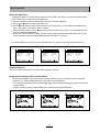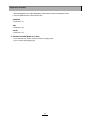
1
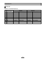
S/M No. TCM003NEF0
Color Television
Chassis : CM-003N
Model
: DTH-14/20 V1FSN
DTH-14/20 V3FSN
DTH-14/20 V4FSN
MANUAL DE SERVICIO
AUG. 2001
TABLE OF CONTENTS
Safety Precautions ................................................................................................................ 2
Product safety servicing guidelines for audio - video products ................................................................ 2
Product safety dervicing guidelines for color television receivers ............................................................ 3
Specifications ......................................................................................................................... 5
User’s Instruction ................................................................................................................... 6
Block Diagram ......................................................................................................................... 19
Alignment Instructions........................................................................................................... 20
Service mode adjustments ...................................................................................................................... 20
Assembly adjustments ............................................................................................................................ 21
SCHEMATIC DIAGRAM ........................................................................................................... 25
PRINTED CIRCUIT BOARD .................................................................................................... 26
Exploded View ......................................................................................................................... 27
Service Parts List / Recommendable Spare Parts List ....................................................... 33
APPENDIX (“Appendix is provided only by internet [http://svc.dwe.co.kr]”)
IC Description ......................................................................................................................... 39
Troubleshooting Guide ........................................................................................................... 47
No power ................................................................................................................................................ 47
No picture ............................................................................................................................................... 48
No sound ................................................................................................................................................ 49
CH don’t stop .......................................................................................................................................... 50
No color .................................................................................................................................................. 51
No vertical deflection ............................................................................................................................... 51
No on-screen display .............................................................................................................................. 52
Remote control does not operate ............................................................................................................ 52
1
PRODUCT SAFETY SERVICING GUIDELINES FOR AUDIO - VIDEO PRODUCTS
CAUTION : DO NOT ATTEMPT TO MODIFY THIS PRODUCT IN ANY WAY.
NEVER PEPFORM CUSTOMIZED INSTALLATIONS WITHOUT MANUFACTURER’S APPROVAL. UNAUTHORIZED MODIFICATIONS WILL NOT ONLY VOID
THE WARRANTY, BUT MAY LEAD TO YOUR BEING LIABLE FOR ANT RESULTING PROPERTY DAMAGE OR USER INJURY.
SERVICE WORK SHOULD BE PERFORMED ONLY AFTER YOU ARE THOROUGHLY FAMILIAR WITH ALL OF THE FOLLOWING SAFETY CHECKS AND
SERVICING GUIDELINES. TO DO OTHERWISE, INCREASES THE RISK OF
POTENTIAL HAZARDS AND INJURY TO THE USER.
WHILE SERVICING, USE AN ISOLATION TRANSFORMER FOR PROTECTION
FROM A.C.LINE SHOCK.
SUBJECT : X-RADIATION
1. BE SURE PROCEDURES AND INSTRUCTIONS TO ALL SERVICE PERSONNEL COVER THE SUBJECT OF X-RADIATION. THE ONLY POTENTIAL
SOURCE OF X-RAYS IN CURRENT T.V. RECEIVERS IS THE PICTURE TUBE.
HOWEVER, THIS TUBE DOES NOT EMIT X-RAYS WHEN THE HIGH VOLTAGE IS AT THE FACTORY SPECIFIED LEVEL. THE PROPER VALUE IS
GIVEN IN THE APPLICABLE SCHEMATIC. OPERATION AT HIGHER VOLTAGES MAY CAUSE A FAILURE OF THE PICTURE TUBE OR HIGH VOLTAGE
SUPPLY AND UNDER CERTAIN CIRCUMSTANCES, AMY PRODUCE RADIATION IN EXCESS OF DESIRABLE LEVELS.
2. ONLY FACTORY SPECIFIED C.R.T ANODE CONNECTORS MUST BE USED.
DEGAUSSING SHIELDS ALSO SERVE AS X-RAY SHIELD IN COLOR SETS.
ALWAYS RE-INSTALL THEM.
3. IT IS ESSENTIAL THAT SERVICE PERSONNEL HAVE AVAILABLE AN ACCURATE AND RELIABLE HIGH VOLTAGE METER. THE CALIBRATION OF THE
METER SHOULD BE CHECKED PERIODICALLY AGAINST A REFERENCE
STANDARD. SUCH AS THE ONE AVAILABLE AT YOUR DISTRIBUTOR.
4. WHEN THE HIGH VOLTAGE CIRCUITRY IS OPERATING PROPERLY THERE
IS NO POSSIBILITY OF AN X-RADIATION PROBLEM. EVERY TIME A COLOR
CHASSIS IS SERVICED, THE BRIGHTNESS SHOULD BE RUN UP AND
DOWN WHILE MONITORING THE HIGH VOLTAGE WITH A METER TO BE
CERTAIN THAT THE HIGH VOLTAGE DOES NOT EXCEED THE SPECIFIED
VALUE AND THAT IT IS REGULATING CORRECTLY. WE SUGGEST THAT
YOU AND YOUR SERVICE ORGANIZATION REVIEW TEST PROCEDURES
SO THAT VOLTAGE REGULATION IS ALWAYS CHECKED AS A STANDARD
SERVICING PROCEDURE, AND THAT THE HIGH VOLTAGE READING BE
RECORDED ON EACH CUSTOMER’S INVOICE.
5. WHEN TROUBLESHOOTING AND MAKING TEST MEASUREMENTS IN A
PRODUCT WITH A PROBLEM OF EXCESSIVE HIGH VOLTAGE, AVOID
BEING UNNECESSARILY CLOSE TO THE PICTURE TUBE AND THE HIGH
VOLTAGE SUPPLY. DO NOT OPERATE THE PRODUCT LONGER THAN IS
NECESSARY TO LOCATE THE CAUSE OF EXCESSIVE VOLTAGE.
6. REFER TO HV, B+ AND SHUTDOWN ADJUSTMENT PROCEDURES
DESCRIBED IN THE APPROPRIATE SCHEMATIC AND DIAGRAMS (WHERE
USED).
SAFETY CHECKS
AFTER THE ORIGINAL SERVICE PROBLEM HAS BEEN CORRECTED, A
CHECK SHOULD BE MADE OF THE FOLLOWING :
SUBJECT : FIRE & SHOCK HAZARD
1. BE SURE THAT ALL COMPONENTS ARE POSITIONED IN SUCH A WAY AS
TO AVOID POSSIBILITY OF ADJACENT COMPONENT SHORTS. THIS IS
ESPECIALLY IMPORTANT ON THOSE MODULES WHICH ARE TRANSPORTED TO AND FROM THE REPAIR SHOP.
2. NEVER RELEASE A REPAIR UNLESS ALL PROTECTIVE DEVICES SUCH AS
INSULATORS, BARRIERS, COVERS, SHIELDS, STRAIN RELIEFS, POWER
SUPPLY CORDS, AND OTHER HARDWARE HAVE BEEN REINSTALLED PER
ORIGINAL DESIGN. BE SURE, THAT THE SAFETY PURPOSE OF THE POLARIZED LINE PLUG HAS NOT BEEN DEFEATED.
3. SOLDERING MUST BE INSPECTED TO DISCOVER POSSIBLE COLD SOLDER JOINTS, SOLDER SPLASHES OF SHARP SOLDER POINTS. BE CERTAIN TO REMOVE ALL LOOSE FOREIGN PARTICLES.
4. CHECK FOR PHYSICAL EVIDENCE OF DAMAGE OF DETERIORATION TO
PARTS AND COMPONENTS, FOR FRAYED LEADS, DAMAGED INSULATION
(INCLUDING A.C. CORD), AND REPLACE IF NECESSARY. FOLLOW ORIGINAL LAYOUT, LEAD LENGTH AND DRESS.
5. NO LEAD OR COMPONENT SHOULD TOUCH A RECEIVING TUBE OR A
RESISTOR RATED AT 1 WATT OR MORE. LEAD TENSION AROUND PROTRUDING METAL SURFACES MUST BE AVOIDED.
6. ALL CRITICAL COMPONENTS SUCH AS FUSES, FLAMEPROOF RESISTOR,
CAPACITORS, ETC. MUST BE REPLACED WITH EXACT FACTORY TYPES.
DO NOT USE REPLACEMENT COMPONENTS OTHER THAN THOSE SPECIFIED OR MAKE UNRECOMMENDED CIRCUIT MODIFICATIONS.
7. AFTER RE-ASSEMBLY OF THE STE ALWAYS PERFORM AN A.C. LEAKAGE
TEST ON ALL EXPOSED METALLIC PARTS OF THE CABINET. (THE CHANNEL SELECTOR KNOB, ANTENNA TERMINALS, HANDLE AND SCREWS)TO
BE SURE THE SET IS SAFE TO OPERATE WITHOUT DANGER OF ELECTRICAL SHOCK. DO NOT USE A LINE ISOLATION TRANSFORMER DURING
THIS TEST USE AN A.C. VOLTMETER, HAVING 5000 OHMS PER VOLT OR
MORE SENSITIVITY, IN THE FOLLOWING MANNER : CONNECT A 1500 OHM
10 WATT RESISTOR, PARALLELED BY A .15 MFD. 150V A.C. TYPE CAPACITOR BETWEEN A KNOWN GOOD EARTH GROUND (WATER POPE, CONDUIT, ETC.) AND THE EXPOSED METALLIC PARTS, ONE AT A TIME.
MEASURE HE A.C. VOLTAGE ACROSS THE COMBINATION OF 1500 OHM
RESISTOR AND. 15 MFD CAPACITOR. REVERSE THE A.C. PLUG AND
REPEAT A.C. VOLTAGE MEASUREMENTS FOR EACH EXPOSED METALLIC
PART. VOLTAGE MEASURED MUST NOT EXCEED .75 VOLTS R.M.S THIS
CORRESPONDS TO 0.5 MILLIAMP A.C. NAY VALUE EXCEEDING THIS LIMIT
CONSTITUTES A POTENTIAL SHOCK HAZARD AND MUST BE CORRECTED
IMMEDIATELY.
SUBJECT : IMPLOSION
1. ALL DIRECT VIEWED PICTURE TUBES ARE EQUIPPED WITH AN INTEGRA
IMPLOSION PROTECTION SYSTEM. BUT CARE SHOULD BE TAKEN TO
AVOID DAMAGE DURING INSTALLATION. AVOID SCRATCHING THE
TUBE. OF SCRATCHED REPLACE IT.
2. USE ONLY RECOMMENDED FACTORY REPLACEMENT TUBES.
SUBJECT : TIPS ON PROPER INSTALLATION
1. NEVER INSTALL ANY PRODUCT IN A CLOSED-IN RECESS, CUBBYHOLE
OR CLOSELY FITTING SHELF SPACE, OVER OR CLOSE TO HEAT DUCT, OR
IN THE PATH OF HEATED AIR FLOW.
2. AVOID CONDITIONS OF HIGH HUMIDITY SUCH AS : OUTDOOR PATIO
INSTALLATIONS WHERE DEW IS A FACOR, NEAR STEAM RADIATORS
WHERE STEAM LEAKAGE IS A FACTOR, ETC.
3. AVOID PLACEMENT WHERE DRAPERIES MAY OBSTRUCT REAR VENTING.
THE CUSTOMER SHOULD ALSO AVOID THE USE OF DECORATIVE
SCARVES OR OTHER COVERINGS WHICH MIGHT OBSTRUCT VENTILATION.
4. WALL AND SHELF MOUNTED INSTALLATIONS USING A COMMERCIAL
MOUNTING KIT, MUST FOLLOW THE FACTORY APPROVED MOUNTING
INSTRUCTIONS. A PRODUCT MOUNTED TO A SHELF OR PLATFORM MUST
RETAIN ITS ORIGINAL FEET ( OR THE EQUIALENT THICKNESS IN SPACERS) TO PROVIDE ADEQUATE AIR FLOW ACROSS THE BOTTOM, BOLTS
OR SCREWS USED FOR FASTENERS MUST NOT TOUCH ANY PARTS OR
WIRING. PERFORM LEAKAGE TEST ON CUSTOMIZED INSTALLATIONS.
5. CAUTION CUSTOMERS AGAINST THE MOUNTING OF A PRODUCT ON
SLOPING SHELF OR A TILTED POSITION, UNLESS THE PRODUCT IS PROP
ERLY SECURED.
6. A PRODUCT ON A ROLL-ABOUT CART SHOULD BE STABLE ON ITS MOUNTING TO THE CART. CAUTION THE CUSTOMER ON THE HAZARDS OF TRYING TO ROLL A CART WITH SMALL CASTERS ACROSS THRESHOLDS OR
DEEP PILE CARPETS.
7. CAUTION CUSTOMERS AGAINST THE USE OF A CART OR STAND WHICH
HAS NOT BEEN LISTED BY UNDERWRITERS LABORATORIES. INC. FOR
USE WITH THEIR SPECIFIC MODEL OF TELEVISION RECEIVER OF
GENERICALLY APPROVED FOR USE WITH T.V.S OF THE SAME OR
LARGER SCREEN SIZE.
8. CAUTION CUSTOMERS AGAINST THE USE OF EXTENSION CORDS,
EXPLAIN THAT A FOREST OF EXTENSIONS SPROUTING FROM A SINGLE
OUTLET CAN LEAD TO DISASTROUS CONSEQUENCES TO HOME AND
FAMILY.
SUBJECT : GRAPHIC SYMBOLS
THE LIGHTNING FLASH WITH ARROWHEAD SYMBOL,
WITHIN AN EQUILATERAL TRIANGLE, IS INTENDED
TO ALERT THE SERVICE PERSONNEL TO THE PRESENCE OF UNINSULATED “DANGEROUS VOLTAGE”
THAT MAY BE OF SUFFICIENT MAGNITUDE TO CONSTITUTE A RISK OF ELECTRIC SHOCK.
THE EXCLAMATION POINT WITHIN AN EQUILATERAL
TRIANGLE IS INTENDED TO ALERT THE SERVICE
PERSONNEL TO THE PRESENCE OF IMPORTANT
SAFETY INFORMATION ON SERVICE LITERATURE.
2
PRODUCT SAFETY SERVICING GUIDELINES FOR COLOR TELEVISION RECEIVERS
GRAPHIC SYMBOLS :
CAUTION : Do not attempt to modify this product in any way. Unauthorized modifications will not only void the warranty, but may lead to
your being liable for any resulting property damage or user injury.
Servie work should be performed only after you are thoroughly
familiar with all of the following safety checks and servicing guidelines. To do otherwise, increases the risk of potential hazards and
injury to the user.
The ligntning flash with arrowhead symbol,
within an equilateral triangle, is intended to alert
the service personnel to the presence of uninsulated “dangerous voltage” that may be of suffcienty magnitude to constitute a risk of electric
shock.
SAFETY CHECKS
The exclamation point within an equilateral triangle is intended to alert the service personnel
to the presence of important safety information
in service literature.
After the original service problem has been corrected, a check should
be made of the following :
SUBJECT : FIRE & SHOCK HAZARD
Fuse symbol is printed on pcb adjacent to the
fuse, with “RISK OF FIRE REPLACE FUSE AS
MARKED”. The symbol is explained in the service manual sith the following wording or equivalent.
1. Be sure that all components are positioned in such a way as to
avoid possibility of adjacent component shorts. This is especially
important on those chassis which are transported to and from the
repair shop.
2. Never release a repair unless all protective devices such as insulators, barriers, covers, shields, strain reliefs, and other hardware
have been reinstalled per original design.
3. Soldering must be inspected to discover possible cold solder joints,
frayed leads, damaged insulation (including A.C. cord), solder
splashes or sharp solder points. Be certain to remove all loose foreign particals.
4. Check for physical evidence of damage or deterioration to parts
and components, and replace if necessary follow original layout,
lead length and dress.
5. No leads or components should touch a receiving tube or a resistor
rated at 1 watt or more. Lead tension around protruding metal surfaces must be avoided.
6. All critical components such as fuses, flameproof resistors, capacitors, etc. must be replaced with exact factory types. Do not use
replacement components other than those specified or make
unrecommended circuit modifications.
7. After re-assembly of the set always perform an A.C. leakage test
on all exposed metallic parts of the cabinet, ( the channel selector
knob, antenna terminals, handle and screws ) to be sure the set is
safe to operate without danger of electrical shock. Do not use a
line isolation transformer during this test. Use an A.C. voltmeter,
having 5000 ohms per volt or more sensitivity, in the following
manner : connect a 1500 ohm 10 watt resistor, paralleled by a 15
mfd. 150V A.C. type capacitor between a known good earth
ground (9water pipe, conduit, etc.) and the exposed metallic parts,
one at a time. Measure the A.C. voltage across the combination of
1500 ohm resistor and 0.15 MFD capacitor. Reverse the A.C. plug
and repeat A.C. voltage measurements for each exposed metallic
part. Voltage measured must not exceed 0.75 volts R.M.S. This
corresponds to 0.5 milliamp A.C. Any value exceeding this limit
constitutes a potential shock hazard and must be corrected immediately.
“ CAUTION : FOR CONTINUED PROTECTION AGAINST FIRE
HAZARD, REPLACE ONLY WITH SAME TYPE ( 4A, 125V)” and
“ ATTENTION : AFIN D’ASSU UNE PROTECTION PERMANENTE
CONTRE LES RISQUES D’INCENDIE, REMPLACER UNIQUEMENT PAR UN FUSIBLE DE MEME TYPE ET DE “ 4A, 125V”.
SUBJECT : X-RADIATION
1. Be sure procedures and instructions to all service personnel cover
the subject of X-rays in current T.V. receivers is the picture tube.
However, this does not emit X-rays when the high voltage is
at the factory specified level. The proper value is given in the applicable schematic. Operation at higher voltages may cause a failure
of the picture tube or high voltage supply and, under certain circumstances, may produce radiation in excess of desirable levels.
2. Only factory specified C.R.T. anode connectors must be used.
Degaussing shields also serve as X-ray shield in color sets.
Always re-install them.
3. It is essential that the serviceman has available an accurae and
reliable high voltage meter. The calibration of the meter should be
checked perio - dically against a reference standard. Such as the
one available at your distributor.
4. When the high voltage circuitry is operating properly there is no
possibility of an X-radiation problem. Every time a color chassis is
serviced, the brightness should be run up and down while monitoring the high voltage with a meter to be certain that the high voltage
does not exceed the specified value and that it is regulating correctly. We suggest that you and your service organization review
test procedures so that voltage regulation is always checked as a
standard servicing procedure. And that the high voltage reading be
recorded on each customer’s invoice.
5. When troubleshooting and making test measurements in a receiver
with a problem of excessive high voltage, avoid being unnecessarily
close to the picture tub eand the high voltage compartment.
Do not operate the chassis longer than is necessary to locate the
cause of excessive voltage.
6. Refer to HV, B+and Shutdown adjustment procedures described in
the appropriate schematic and diagrams(where used).
3
SUBJECT : IMPLOSION
4. Wall and shelf mounted installations using a commercial mounting
kit, must follow the factory approved mounting instructions. A
receiver mounted to a shelf or platform must retain its original
feet ( or the equivalent thickness in spacers ) to provide adequate
are flow across the bottom , bolts or screws used for fasteners
must not touch and parts or wiring. Perform leakage test on customized installations.
5. Caution customers against the mounting of a receiver on sloping
shelf or a tilted position, unless the receiver is properly secured.
6. A receiver on a roll-about cart should be stable on its mounting to
the cart. Caution the customer on the hazards of trying to roll a cart
with small casters across thresholds or deep pile carpets.
7. Caution customers against the use of a cart of stand which has not
been listed by underwriters laboratories, inc. For use with their
specific model of television receiver or generically approved for
use with T.V.’s of the same or larger screen size.
1. All direct viewed picture tubes are equipped with an integral implosion protection system, but care should be taken to avoid damage
during installation. Avoid scratching the tube. If scratched, replace
it.
2. Use only recommended factory replacement tubes.
SUBJECT : TIPS ON PROPER INSTALLATION
1. Never install any receiver in closed-in recess, cubbyhole or colsely
fitting shelf space over, or close to heat duct, or in the path of
heated air flow.
2. Avoid conditions of high humidity such as : Outdoor patio installations where dew is a factor. Near steam radiators where steam
leakage is a factor, etc.
3. Avoid placement where draperies may obstruct rear venting. The
customer should also avoid the use of decorative scarves or other
coverings which might obstruct ventilation.
4
Specifications
MODEL
ITEMS
TV STANDARD
POWER INPUT
POWER CONSUMPTION
TUNING SYSTEM
TUNING RANGES
SOUND OUTPUT
SPEAKER
ANTENNA INPUT IMPEDANCE
AUXILIARY
INPUT TERMINAL
INTERMEDIATE
FREQUENCIES
REMOTE CONTROL
SPCEIAL FUNCTIONS
DTH-14V1FSN
DTH-20V1FSN
DTH-14V3FSN
DTH-20V3FSN
DTH-14V4FSN
DTH-20V4FSN
NTSC-M, PAL N/M
AC160-260V, 50/60 Hz
14”=55W , 20”=70W
Frequency Synthesizer (FS) Tuning System
VHS : 2~13 (12)
UHF : 2~13 (56)
CATV : 1~125 (125)
3W
3 W 8 ohm
75 ohm Unbalanced
Front : Video, Audio, Ear phone
Rear : Video, Audio
Picture IF Carrier Frequency : 45.75 MHz
Sound IF Carrier Frequency : 45.25 MHz
Color Sub-Carrier Frequency : 42.17 MHz
R-43A01
3-Language OSD
With CAPTION
Wake-up/Off Time
Sleep Timer
Power Restore
5
REMARKS
User’s Instruction
Overview of Your Equipment
Your TV comes with a remote control. The section below summarizes the buttons, controls, and terminals that your will
use with your TV.
Your TV’s Front Panel
1 POWER
Use this button to turn your TV or off.
2
CH
Use these buttons to change channels on your TV, or to select items in the menu system.
3
VOL
Use these buttons to change your TV’s volume, to activate selections in the meun system, or to change audio and
video settings.
4 MENU
Use this button to turn the TV’s menu system on and off.
5 STAND-BY(red) indicatior
This indicator lights up when the AC power cord is connected to a power source.
6 Remote Control Receiver
This receiver receives a signal from your remote control. Do not block it.
7 VIDEO IN jack
Use this jack to receive a video signal from another A/V component.
8 AUDIO IN jack
Use this jack to receive an audio signal from another A/V componet.
9 EARPHONE jack
Use this jack to receive an audio signal from your TV.
Your TV’s Back Panel
1 Antenna terminal (ANT)
Use this terminal to attach an antenna or cable system to
your TV.
2 VIDEO IN
This terminal allows the TV to receive a video sighal from
another component, such as a VCR.
3 AUDIO IN
This terminal allows the TV to receive an audio sighal from
another component, such as a VCR.
6
User’s Instruction
Your Remote Control
1. POWER
Use this buttion to turn your TV on or off.
2
2. MUTE
Use to turn the TV’s sound on and off.
1
3
4
3.
CH
Use these buttons to channels on your TV,
or select items in the menu system.
4.
VOL
Use these buttons to change your TV’s volume,
to activate selections in the menu system, or to
change audio and video settings.
4
5
3
5. MENU
Use this button to turn the TV’s menu system on and
off.
9
6. DISPLAY
Use this button to select the TV’s signal source.
10
11
7. INPUT
Use this button to select the TV’s signal source.
6
8
8. VIDEO
Use this button to display video adjustment items.
7
9. 0-9
Use these buttons to change channels.
10. SLEEP
Use this button to program the TV turn off after
a certain time.
11. PREVIOUS
Use this button to return to the previous channel
you were watching.
7
User’s Instruction
Operating Your TV
Once you have connected your TV to an antenna or cable system, plugged the TV in, and put batteries in the remote, you
are ready to use the TV. The first thing you should do is program your TV so it memorizes all of available channels.
Turning Your TV On
1 To turn your TV, press the POWER button on the front panel then.
press the CH , VOL or MENU botton.
You can also use the POWER button on the remote control.
Make sure your TV is plugged in before you try to turn it on.
Programming Your TV’s Channel Memory
Your TV’s memory determines the channels that are availablee using the CH buttons. If a channel is not in memory,
you can tune to it with the number buttons, but not with the CH buttons. Follow these steps to program your TV’s
memory :
1 With the TV on, press the MENU button twice, then “ Set-Up ” menu will appear.
2 Use the CH buttons to select “ Reception ”, the use the VOL button to select ‘Air’ or ‘Cable’. If you
connected an antenna to your TV, select ‘Air’ : If you connected a cable system, select ‘Cable’
3 Use the CH buttons to select “ Memorize Channels ” , then use the VOL button to enter the “ Memorize
Channels ” process. Again press the VOL button to begin.
4 Press the MENU button to return to Set-Up menu.
5 Press the MENU button three times to return to normal TV viewing.
Your TV’s channel memory will not be affected by a power outage. You will not need to re-program the memory unless you
change the type of cable or antenna connected to your TV.
8
User’s Instruction
Changing Channels
You can change channels in three ways :
1 The CH buttons will take you through all memorized channels,
one by one. The CH buttons will not access channels that
have not been programmed into the TV’s memory. For more information
about programming channels into memory, see the section “Programmining your TV’s Channel Memory” on the previous page.
2 The number buttons (0-9) will take you to any channel, even if it has
not been memorized. To change to a channel, enter its number : the
TV will tune to the new channel when you enter the second digit of
the channel.
3 The PREVIOUS button will take you instantly to the last channel you
were watching.
Changing the Volume
1 The change the volume of the TV set, use the VOL buttons on
the remote or on the front panel.
2 To quickly turn off the sound, press the MUTE button on the remote.
The ‘MUTE’ will appear on screen, colored green. To return the
volume to its previous level, press MUTE again.
Changing the TV’s Channel Memory
Your TV’s memory determines the channels that are available using the CH buttons. You can add channels to this
memory or remove them from memory. If a channel is removed from memory, you can tune to with the number buttons,
but you cannot tune to it with the CH buttons.
If there are just one channel memorized, then the Add/Delete Channels function will search the whole channels. But if there
are two or more channel memorized, then the Add/Delete Channels function will search the memorized channels only.
Adding/Deleting a channel to memory
1 Use the number buttons to tune to the channel.
2 Press the MENU button twice, then “Set-Up” menu will display.
3 Use the CH buttons to select “Add/Delete Channels” , then use the VOL button to enter the “Add/
Delete Channels” process.
4 If the channel is not in memory, then use the VOL button to add the channel from memory.
5 If the channel is in memory, then use the VOL button to delete the channel from memory.
6 If you are going to delete other channel, then press the CH buttons until desired channel is selected. And
press the VOL button to delete the channel.
7 Wait 10 seconds, or press the MENU button four times to exit.
9
User’s Instruction
4
5
Add/Delete Channels
6
Add/Delete Channels
Air 11
This channel is in memory.
Press VOL
to delete.
Press CH for other channels.
Add/Delete Channels
Air 11
This channel is in memory.
Press VOL
to delete.
Press CH for other channels.
Press MENU to return
to Set-Up menu.
Air 11
This channel is in memory.
Press VOL
to delete.
Press CH for other channels.
Press MENU to return
to Set-Up menu.
Press MENU to return
to Set-Up menu.
Displaying the Current Channel
1 To quickly see the current channel number and status, press
DISPLAY button on the remote control. The current channel number
and status will be displayed.
Changing the TV’s Input
Normally, your TV displays the signal coming through the antenna terminal.
However, If you’ve connected another component to your TV(such as a VCR) using the Video/Audio input, you will want to
be able to view the signal from the component.
To do this, you will need to switch from the ‘TV’ input to the ‘Line’ Input, as follows.
1 With the TV on, press the MENU button twice, then “set-up” menu will appear.
2 Use the CH buttons to select “Input”.
3 Press the VOL buttons to change from ‘TV’ to ‘Line’.
4 Wait 10 seconds, or press the MENU button to return to normal TV viewing.
1
2
Set-Up
Language :
English
Reception :
Air
Memorize Channels
Add/Delete Channels
Input :
TV
Select
3
Set-Up
Adjust
Next
Set-Up
Language :
English
Reception :
Air
Memorize Channels
Add/Delete Channels
Input :
TV
Select
Adjust
10
Next
Language :
Input :
Select
English
Line
Adjust
Next
User’s Instruction
When it connected an Video/Audio cable from the Video/Audio out jack on the VCR to the Video/Audio in jack on the front
your TV, and your ‘TV’s back panel at the same time, the latter takes precedence of the former.
Adjusting Video Settings
You may wish to adjust the video settings (e. g. contrast or color) to obtain the most pleasing picture. To do so, follow
these directions:
1 With the TV on, press the MENU button. then “Video” menu will appear.
2 The “Settings” item will be selected. Use the VOL buttons to turn Settings to Preset or Custom.
3 Use the CH buttons to select the video setting you wish to adjust. Descriptions of the video settings are on the
next page.
4 Use the VOL buttons to adjust the video setting to the level you prefer.
5 Use the CH buttons to select another video setting to adjust.
6 When you are finished, press the MENU button until menu OSD will be disappeared.
1
2
Video
Settings :
Contrast
Brightness
Sharpness
Color
Tint
Select
3
Video
Video
Custom
Adjust
Settings :
Contrast
Brightness
Sharpness
Color
Tint
Next
4
Select
Settings :
Contrast
Brightness
Sharpness
Color
Tint
Preset
Adjust
Select
Next
5
Preset
Adjust
Next
6
Contrast
Brightness
Returning to the factory settings
If you would like to return to the original video settings, as they were calibrated at the factory, follow these steps :
1 With the TV on, pres the MENU button. then “Video” menu will appear.
2 Press the VOL buttons to set the “Settings” to ‘Preset’.
The TV will remember the ‘Custom’ settings you had previously chosen. When you set “Settings” to “Custom’ agin,
your previous custom settings will be restored.
2
1
Video
Video
Settings :
Contrast
Brightness
Sharpness
Color
Tint
Select
Custom
Adjust
Next
Settings :
Contrast
Brightness
Sharpness
Color
Tint
Select
Preset
Adjust
11
Next
User’s Instruction
Descriptions of video settings
The contrast setting controls the relation between the light and black areas of the screen. If the light areas are too bright
and are losing details, press the
VOL button ; if the picture is gray and lacks contrast, press the VOL button.
The brightness settings controls the overall amount of light in the picture. If the picture is tooo bright, press the
button ; if the picture is too dark, press the VOL button.
VOL
Sharpness controls how the TV displays edges of objects on-screen. If the TV shows multiple vertical lines at the
edges of an object, press the
VOL button ; if the vertical edges of on-screen objects are fuzzy, press the VOL
The color setting controls the intensity of color. If the color is over-saturated, press the VOL
washed out, press the VOL button.
button.
button ; if the color is
The tint setting controls the relationship of red and green in a picture. Tint is especially noticeable in flesh tones. If
flesh tones seem too red or purple, press the VOL button ; if flesh tones are too green, press the VOL button.
Using Timer Functions
Your TV has a built in-clock, and you can set the TV to turn on and off at times that you select. You can also set your TV
to turn off after counting down a certain amount of time.
Setting the Clock
1 With the TV turned on, press the MENU button until “ Time” menu will be displayed.
2 The “Set Clock” item will be selected. Press the VOL buttons to set the clock. If you hold down either
VOL or VOL button, the corresponding numbers will change more quickly.
3 When the clock is set correctly, use the CH buttons to select another “Time” function, or press the MENU button
until menu OSD will be disappeared.
1
2
Time
Set Clock :
Wake-Up time :
Off time :
Sleep Timer :
Select
3
Time
:
:
:
0 min
Adjust
Time
Set Clock :
Wake-Up time :
Off time :
Sleep Timer :
Next
Select
1 2 : 00 AM
:
:
0 min
Adjust
Next
Set Clock :
Wake-Up time :
Off time :
Sleep Timer :
Select
1 2 : 00 AM
:
:
0 min
Adjust
Next
Settings the Wake-up timer
If you enter a time in the “Wake-up time” setting, your TV will automatically turn on at that time. Follow these instructions to
set the “Wake-up time”.
12
User’s Instruction
After Wake-up Timer turned on the TV set, if user do not input the user control (e.g. remote CH or VOL key) within 15 minutes,
the TV set will turn off automatically. If user input the user control within 15 minutes, the TV set will turn on continuously.
It is safety feature for prevent from any kind of problem without human control.
1
2
3
4
With the TV turned on, press the MENU button unil “Time” menu will be displayed.
Use the CH buttons to select “Wake-up time” item.
If you hold down either VOL or VOL button, the corresponding numbers will change more quickly.
When the setting is corret, use the CH buttons to select another “Time” function, or press the MENU button
until menu OSD will be disappeared.
2
1
Set Clock :
Wake-Up time :
Off time :
Sleep Timer :
Select
3
Time
Time
1 2 : 00 AM
:
:
0 min
Adjust
Time
Set Clock :
Wake-Up time :
Off time :
Sleep Timer :
Next
Select
1 2 : 00 AM
:
:
0 min
Adjust
Set Clock :
Wake-Up time :
Off time :
Sleep Timer :
Next
Select
1 2 : 00 AM
:
:
0 min
Adjust
Next
Setting Off Timer
If you enter a time in the “Off time” setting, your TV will automatically turn off at that time. Follow these instrutions
to set the “Off time”.
1 With the TV turned on, press the MENU button until “Time” menu will be displayed.
2 Use the CH buttons to select “Off time” item.
3 If you hold down either VOL or VOL button, the corresponding numbers will change more quickly.
4 When the setting is correct, use the CH buttons to select another “Time” function, or press the MENU button
until menu OSD will be disappeared.
1
2
Time
Set Clock :
Wake-Up time :
Off time :
Sleep Timer :
Select
3
Time
1 2 : 00 AM
:
:
0 min
Adjust
Next
Time
Set Clock :
Wake-Up time :
Off time :
Sleep Timer :
Select
1 2 : 00 AM
:
:
0 min
Adjust
Next
Set Clock :
Wake-Up time :
Off time :
Sleep Timer :
Select
1 2 : 00 AM
11 : 30 PM
0 min
Adjust
Next
Canceling the Wake-up Timer of Off Timer
If you would like to cancel the Wake-up Timer or the Off Timer, Press the
VOL buttons until the timer settings
return to “- -:- -”.
The Wake-up Timer and Off Timer will not function correctly unless the clock has been set.
13
User’s Instruction
Setting the Sleep Timer
The sleep timer allows you to set an amount of time from 15 minutes to 120 minutes. TV will count down the amount
of time you set, then turn itself off. To set the sleep timer :
1 With the TV turned on, press the MENU button until “Time” menu will be displayed.
2 Use the CH buttons to select “Sleep timer” item.
3 Use the VOL buttons to set the sleep time. Each time you press VOL, you step between the available sleep
times : 15min, 30min, 45min, 60min, 90min, or 120min.
4 When the setting is correct, use the CH buttons to select another “Time” function, or press the MENU button
until menu OSD will be disappeared.
5 You can also set the “Sleep Timer” during normal TV viewing, simply by pressing the SLEEP button on the remote
control. This button steps through the available sleep times (see step 3), one by one.
To cancel the Sleep timer, turn the TV off, or set the sleep time to “0” using one of the methods described above.
1
2
Time
Set Clock :
Wake-Up time :
Off time :
Sleep Timer :
Select
3
Time
1 2 : 00 AM
06 : 30 AM
1 1 : 30 PM
0 min
Adjust
Next
Time
Set Clock :
Wake-Up time :
Off time :
Sleep Timer :
Select
1 2 : 00 AM
06 : 30 AM
1 1 : 30 PM
0 min
Adjust
Next
Set Clock :
Wake-Up time :
Off time :
Sleep Timer :
Select
1 2 : 00 AM
06 : 30 AM
1 1 : 30 PM
0 min
Adjust
Next
Additional Features
This section contains descriptions of the more advanced features of your TV.
Changing the Language of the On-screen Menus
You can choose to display the on-screen menus in English, Spanish, French. To change the on-screen language :
1 With the TV on, press the MENU button twice, then “Set-Up” menu will appear.
2 The “Language” item will be selected. Press the VOL buttons to select the language you want to use : English,
Spanish, French.
3 To return normal TV viewing, press the MENU button until menu OSD will be disappeared.
14
User’s Instruction
Captioning
Many TV shows contains “closed captions”. These captions are hidden words that can be displayed on your TV
screen. There are two types of these words : “captions” usually follow the action on-screen, providing a written version
of the dialogue, narration, and sound effects ; “text” is not usually related to the action on-screen, often providing
information such as news or weather. A TV program might be providing more than one set of captions or one set of text.
To set your TV to display captions or text.
1 With the TV turned on, press the MENU button until “Special” menu will be displayed.
2 The “Closed Caption” item be selected. To turn captioning on, use the VOL buttons to select Captions
(C1 or C2) or Text (T1 or T2). At the time these instructions were written, only C1 is normally available, but feel free
to try the other selections.
3 Wait 10 seconds, or press the MENU button to return to normal TV viewing. Your setting will remain intact until you
change it.
2-1
Special
1
Special
Closed Caption :
CC on Mute :
Power Restore :
System : AUTO
Select
Closed Caption :
CC on Mute :
Power Restore :
System : AUTO
OFF
OFF
OFF
Adjust
2-2
Special
Select
Exit
C1
OFF
OFF
Adjust
Closed Caption :
CC on Mute :
Power Restore :
System : AUTO
Exit
Select
T1
OFF
OFF
Adjust
Exit
CC on Mute
When the sound is muted, user can select the caption display. It will display the caption content instead of sound mute.
1 With the TV turned on, press the MENU button until “Special” menu will be displayed.
2 Use the CH buttons to select “CC on Mute” item.
3 Use the VOL buttons to select “C1” or “C2”.
1
2
Special
Closed Caption :
CC on Mute :
Power Restore :
System : AUTO
Select
3
Special
C1
OFF
OFF
Adjust
Special
Closed Caption :
CC on Mute :
Power Restore :
System : AUTO
Exit
Select
Adjust
2-2
Special
Closed Caption :
CC on Mute :
Power Restore :
System : AUTO
Select
Adjust
C1
C2
OFF
Exit
15
C1
OFF
OFF
Closed Caption :
CC on Mute :
Power Restore :
System : AUTO
Exit
Select
Adjust
C1
C1
OFF
Exit
User’s Instruction
Power Restore
User can select the On/Off status when the power cord put into the wall outlet. If user have a cable box with AC outlet,
then user can connect the TV power cord to the AC outlet and control the TV without TV remote control. This function
is rarely used for home use, so special care is needed while using.
1 With TV turned on, press the MENU button until “Special” menu will be displayed.
2 Use the CH buttons select “Power Restore” item.
3 Use the VOL buttons to select “On” or “Off”.
1
2
Special
Closed Caption :
CC on Mute :
Power Restore :
System : AUTO
Select
3
Special
Adjust
C1
C1
OFF
Special
Closed Caption :
CC on Mute :
Power Restore :
System : AUTO
Exit
Select
Adjust
C1
C1
OFF
Closed Caption :
C1
CC on Mute : OFF
Power Restore : On
System : AUTO
Exit
Select
Adjust
Exit
System
User can select the AUTO/PAL-M/PAL-N/NTSC color system modes.
If you have no color problem when see the FF mode of VCR or non standard signal, you must choose the NTSC of color
system modes.
1. With the TV turned on, press the MENU button until “Special” menu will be displayued.
2. Use the CH buttons select “system” item.
3. Use the VOL buttons to selcet “AUTO”, “PAL-M”, “PAL-N” or “NTSC”
1
2
Special
Closed Caption : OFF
CC on Mute : OFF
Power Restore : OFF
System : AUTO
Select
Adjust
Closed Caption : OFF
CC on Mute : OFF
Power Restore : OFF
System : AUTO
Exit
3-2
Special
Select
Adjust
Closed Caption : OFF
CC on Mute : OFF
Power Restore : ON
System : AUTO
Exit
3-3
Special
Closed Caption : OFF
CC on Mute : OFF
Power Restore : ON
System : PAL-M
Select
3-1
Special
Special
Adjust
Select
Adjust
Exit
3-4
Special
Closed Caption : OFF
CC on Mute : OFF
Power Restore : ON
System : PAL-N
Exit
Select
Adjust
16
Closed Caption : OFF
CC on Mute : OFF
Power Restore : ON
System : NTSC
Exit
Select
Adjust
Exit
User’s Instruction
Troubleshooting
Your Daewoo television is designed to give you trouble-free performance for many years. If you have a problem with
your TV, try the solutions listed below.
If the suggestions listed below do not solve your problem, contact your Daewoo dealer or an authorized Daewoo service
center. You can also call Daewoo directly at 1-800-DAEWOO8.
There is no pictrue or sound, or the TV won’t turn on.
• Make sure the TV is plugged in.
• Make sure the MUTE is not set.
• Make sure the power is on.
• If there is neither picture or sound, unplug the TV for 30 seconds. then plug it in and try again.
There is no picture or sound on some UHF channels.
• Try another station. If the other stations are OK, it may be a station problem.
• Check that the antenna is connected, is in good working order, has no broken wires, and is adjusted correctly.
• See if anything is interfering with the antenna signal.
• Make sure the AIR/CABLE setting is correct.
The sound is OK, but he picture is poor.
• Try another station. If the other stations are OK, it may be a station problem.
• Check that the antenna is connected and is in good working order, has no broken wiresm and is adjusted correctly.
The picture is OK, but the sound is poor.
• Try another station. If the other stations are OK, it may be station problem.
• Check that the antenna is connected, is in good working order, has no broken wires, and adjusted correctly.
There is poor reception on some channels.
• Try another station. If the other stations are OK, it may be a station problem.
• Check that the antenna is connected, is in good working order, has no broken wires, and is adjusted correctly.
You cannot tune to a cable channel.
• Make sure the AIR/CABLE setting is correct.
• The channel may not be programmed into memory. USER’S INSTRUCTION
The picture rolls, slants, shows lines, is grainy, has poor color, or has ghosts.
• Try another station. If the other station are OK, it may be a station problem.
• Check that the antenna is connectedm is in good working order, has no broken wires and is adjusted correctly.
• See of anything is interfering with the antenna signal.
The remote control does not work.
• Make sure the TV is plugged in.
• Make sure there are fresh batteries in the remote control.
• Make sure there is nothing blocking the remote control signal.
17
User’s Instruction
WARRANTY
Daewoo Electronics Corporation of America warrants each new electronic product manufactured by it to be free from
defective material and workmanship and agrees to remedy any such defect or to furnish a new part ( at the Company’s
option ) in exchange for any part of any unit of its manufacture shich under normal installation, use, and service disclosed
such defect, provided the unit is delivered by the owner to us or to our authorized distributor from whom purchased or
authorized service station, intact for our examination with all transportation charges prepaid to our factory. To establish and
receive warranty service at our factory or authorized service facilities, proof of purchase/dated sales invoice is required
Return authorization must be obtained before any merchandise is returned to the factory.
This warranty does not extend to any of our electronic products which have been subjected to misuse, neglect, accident,
incorrect wiring not our own, improper installation, unauthorized modification, or to use in violation of instructions furnished
by us, nor units which have been repaired or altered outside of our factory, nor to cases where the serial number thereof
has been removed, defaced, or changed.
This warranty is in lieu of all warranties expressed or implied and no representative or person is authorized to assume
for us any other liability in connection with the sake of our electronic products.
Over-the-counter exchange for units that are initially defective
“Initially defective” is described as when the dealer opens the unit and finds that it is inoperative or a customer opens
a new unit and finds that it is inoperable. This unit may be returned to the factory by the dealer for exchange. Under no
circumstances will the customer be permitted to return the defective unit directly to the factory. Exchange must be
directly with the dealer.
Model
DTH-14V1FSN
DTH-20V1FSN
DTH-14V3FSN
DTH-20V3FSN
DTH-14V4FSN
DTH-20V4FSN
Parts
1 year
1 year
1 year
1 year
1 year
1 year
Labor
90 days
90 days
90 days
90 days
90 days
90 days
Picture Tube
2 years
2 years
2 years
2 years
2 years
2 years
18
Block Diagram
19
Alignment Instructions
1. SERVICE MODE ADJUSTMENTS
Follow the steps below whenever service adjustment is required. See Table-A and Table-B to determine if service
adjustments are required.
1) How to enter the service mode using the user remote control.
• Turn the set on.
• Direct the remote control to the reception window of TV.
• Push buttons of remote control in sequence as follows.
1 ---> MUTE ---> DISPLAY ---> MUTE
• Then, the screen will appear as follows.
• Using the channel up or channel down button, select the item you wish to adjust.
(The color of selected item turns into the red.)
• Press the volume up or down button to enter in the service mode you wish to adjust.
2) How to memorize the adjusted values in the service mode.
• Must press DISPLAY button the state which the screen is displaying each of service menus
after all adjustments are completed each of all service menu.
Table-A : Adjust the values of service mode when a part is replaced.
PART
REPLACED
ADJUSTMENT
N OT E S
NECESSARY UNNECESSARY
I701
O
(U-COM)
I101
Data is stored in I703.
O
(MAIN)
Initial setting values are written from I701.
Adjusting ltems
I703
(EEPROM)
CRT
O
O
S5
RFAGCD
S6
H.PHASE.V.POSI/V.SIZE
S8
RD/BD/RB/GB/BB
S9
Subbrightness
Adjust items related to picture tube only. ( White Balance adjustment )
20
Alignment Instructions
Table-B
MODE
S2
S5
ADJUSTMENT ITEMS
-
-
Video Level (VIDEOL)
RF AGC Delay (RFAGCD)
7
0~7
0 ~ 63
Must be set to 7
Align RF AGC threshold
0 ~ 31
-
Must be set to 20
Select AGC reference voltage
0 ~ 31
VCR VCR/RF NOT USE
Align sync to flyback pulse, using internal cross pattern (S7)
0 ~ 63
0 ~ 127
Align vertical DC bias, using internal cross pattern (S7)
Align vertical amplitude, using internal cross pattern (S7)
Vertical Linearity
Vertical S-Correction (V SC)
*
*
NO
0
0 ~ 31
0 ~ 31
(Must be set to 16)
Must be set to 6
No Sd Off
60 ~ 50 Hz
YES
4
0 ~ 31
(Automatically turn off in 15min for no received signal)
60 ~ 50 Hz
60 ~ 50 Hz
22
0
0 ~ 63
0 ~ 127
60 ~ 50 Hz
Internal Black
3
-
0 ~ 31
-
Internal 100% White
Internal 60% White
-
-
Internal Cross Pattern
Red Drive (RD)
-
0 ~ 127
Display internal CROSS pattern
Align RED OUT AC level
0 ~ 15
0 ~ 127
Must be set to 10
Align BLUE OUT AC level
0 ~ 255
0 ~ 255
Align RED OUT DC level
Align GREEN OUT DC level
0 ~ 255
0 ~ 127
Align BLUE OUT DC level
Align common RGB DC level
FF CHK VCR
Horizontal Phase (H.PHASE)
Vertical Position (V.POSI)
Vertical Size (V.SIZE)
S7
S8
Green Drive (GD)
Blue Drive (BD)
Red Bias (RB)
Green Bias (GB)
Blue Bias (BB)
Subbrightness
S9
S12
REMARKS
Screen Adjustment
Auto RF AGC
FM Level (FM.LEV)
AGC Point
S6
DATA
INITIAL RANGE
*
20
3.75
*
*
14
*
*
*
*
*
Contrast
Tint
27
35
0 ~ 27
0 ~ 27
Color
Forwarding Mode
35
-
0 ~ 27
Display internal BLACK pattern
Display internal 100% WHITE
Display internal 60% WHITE
Factory Initialization
* indicates the items with different settings each of sets
2. ASSEMBLY ADJUSTMENTS
1) SCREEN ADJUSTMENT (S2)
• Enter the service mode and select service adjustment S2.
• You can see the one horizontal line on the screen.
• Adjust the Screen Control Volume (located on FBT) so that the horizontal line onscreen may be
disappeared.
• Press the volume up or down button to exit in the screen adjustment mode.
NOTE
IN THE SCREEN ADJUSTMENT MODE, DONT PRESS OTHER BUTTONS EXCEPT VOLUME UP OR DOWN BUTTON.
21
Alignment Instructions
2) FOCUS ADJUSTMENT
• Turn is a local station and adjust the Focus Control knob (located on FBT) for best picture
details at hight condition.
3) RF AGC DELAY ADJUSTMENT (S5)
• Receive a good local channel.
• Enter the service mode and select service adjustment S5.
• You can see the OSD as shown in below.
• Select RFAGCD item, press the volume up or down button until noise or beat in picture disappears.
• Press the DISPLAY button to memorize the data.
4) GEOMETRIC ADJUSTMENTS (S6)
• Enter the service mode and select service adjustment S7.
• Whenever you select the “S7” using the volume up or down button, the screen is changing like this.
NORMAL
BLACK
WHITE100
WHITE60
CROSS
• Using the volume up or down button, select internal cross pattern.
• Select service adjustment S6
• You can see the OSD as shown in below.
4-1. Horizontal Position Adjustment
• Select H.PHASE item, adjust H.PHASE data value to obtain proper horizontal centering of the
internal cross pattern at the left and right of the screen.
4-2. Vertical Position Adjustment
• Select V.POSI item, adjust V.POSI data value to center the raster properly on the screen.
22
Alignment Instructions
4-3. Vertical Size Adjustment
• Select “V.SIZE” item, adjust “V.SIZE” data value to proper vertical size as follows.
5) WHITE BALANCE ADJUSTMENT (S8)
• Receive a good local channel.
• Enter the service mode and select service adjustment S8.
• You can see the OSD as shown in below.
• Using volume up or volume down, adjust service adjustment data of RD/GD/BD and RB/GB/BB until a good
gray scale with normal whites is obtained. ALIGNMENT INSTRUCTIONS
• Press the DISPLAY button to memorize the data.
6) DIGITAL PRESET (D.P) ADJUSTMENTS (S9)
SUBBRIGHTNESS ADJUSTMENT
• Receive a good local channel.
• Enter the service mode and select service adjustment S9.
• You can see the OSD as shoown in below.
23
Alignment Instructions
• Select Subbrightness item, adjust Subbrightness data value to obtain normal brightness level.
• Press the DISPLAY button to memorize the data.
CONTRAST
• Fixed value = 27
TINT
• Fixed value = 35
COLOR
• Fixed value = 25
7) FACTORY OUTGOING MODE ( S12 : FACT )
• If you select the S12, then the set becomes factory outgoing status.
• You can see the OSD “outgoing OK”
24
SCHEMATIC DIAGRAM
25
PRINTED CIRCUIT BOARD
26
EXPLODED VIEW
1. DTH-14V1FSN
27
EXPLODED VIEW
2. DTH-20V1FSN
28
EXPLODED VIEW
3. DTH-14V3FSN
29
EXPLODED VIEW
4. DTH-20V3FSN
30
EXPLODED VIEW
5. DTH-14V4FSN
31
EXPLODED VIEW
6. DTH-20V4FSN
32
Service Parts List
CAUTION
“ ® ” Parts recommended for stock.
“ ” Safety critical component, Replace only with genuine Daewoo safety part.
LOC
®
PART CODE
LOC
DESCRIPTION
®
PART CODE
PTMPMSH529
PART NAME
DESCRIPTION
PCB MAIN MANUAL AS
DTH-14V1FSN
48B4343A01
TRANSMITTER REMOCON R-43A01 (AA)
PTACPWH403
ACCESSORY AS
DTH-14V4FS
C101 CEXF1H109V
C ELECTRO
50V RSS 1MF (5X11) TP
ANT ROD
S3BW216B (L=600 MM)
C102 CEXF1C101V
C ELECTRO
16V RSS 100MF (6.3X11) TP
R6P/LN
C103 CEXF1H229V
C ELECTRO
50V RSS 2.2MF (5X11) TP
C MYLAR
100V 0.033MF J (TP)
00010 4850A02510
00030 4850Q00810
BATTERY
00040 4850A00650
TRANS ANT MATCHING
YSC-T-07 BR
C104 CMXM2A333J
00050 48586003S1
MANUAL INSTRUCTION
SPAIN
C105 CEXF1C471V
C ELECTRO
16V RSS 470MF (10X12.5)TP
BAG INSTRUCTION
L.D.P.E T0.05X250X400
C106 CEXF1H109V
C ELECTRO
50V RSS 1MF (5X11) TP
COVER BACK AS
DTH-14V1FS
C107 CEXF1H228V
C ELECTRO
50V RSS 0.22MF (5X11) TP
COVER BACK
HIPS BK
C109 CCZF1H103Z
C CERA
50V F 0.01MF Z
CLOTH BLACK
FELT 100X20X0.7
C110 CCZF1H103Z
C CERA
50V F 0.01MF Z
SPEC PLATE
150ART P/E FILM (C/TV)
C111 CCZF1H103Z
C CERA
50V F 0.01MF Z
DTH-14V1FS
C112 CCZF1H103Z
C CERA
50V F 0.01MF Z
STAPLE PIN
18M/M J D O
C113 CCZF1H103Z
C CERA
50V F 0.01MF Z
BOX CARTON
SW-2 DTQ-1463FW
C301 CMXM2A103J
C MYLAR
100V 0.01MF J (TP)
C ELECTRO
50V RSS 4.7MF (5X11) TP
C ELECTRO
50V RSS 10MF (5X11) TP
M821 4858213800
PTBCSHH427
M211 4852151401
M211A 4857817640
M541 4855415800
PTPKCPH427
10 6520010100
M801 4858038700
PACKING AS
M811 4858186700
PAD
EPS 14V1
C302 CEXF1H479V
M821 4858210600
BAG P.E
L.D.P.E T0.03X1000X900
C303 CEXF1H100V
COIL DEGAUSSING
DC-1450
C305 CEXF1H101V
C ELECTRO
50V RSS 100MF (8X11.5) TP
C CERA
500V SL 10PF D (TAPPING)
58G0000084
®
PART NAME
48519A4710
CRT GROUND NET
1401S-1015-1P
C307 CXSL2H100D
PTCACAH529
CABINET AS
DTH-14V1FSN
C308 CMXM2A104J
C MYLAR
100V 0.1MF J (TP)
C ELECTRO
25V RUS 1000MF (13X20) TP
CRT1 PTRTPWH529
CRT AS
DTH-14V1FSN
C310 CEXF1E102C
V01 58D0000082
COIL DY
ODY-M1489
C311 CEXD1H229Q
C ELECTRO
50V RT 2.2MF (6.3X11) TP
V02 2233030001
PAINT LOCK
760G
C401 CCXB2H102K
C CERA
500V B 1000PF K (TAPPING)
19X30 BEIGE
C403 CCYB2H103K
C CERA
500V B 0.01MF K
C MYLAR
1.6KV BUP 7200PF J
V03 2TC26019BE
TAPE CLOTH
V04 2224050026
BOND SILICON
RTV 122 CARTRIDGE
C404 CMYH3C722J
V05 4850PM001-
MAGNET CP
NY-225 (MINI NECK)
C405 CEXF2C109V
C ELECTRO
160V RSS 1MF (6.3X11) TP
RUBBER WEDGE
HMR 28 SR (|0X54)
C406 CMYE2D514J
C MYLAR
200V PU 0.51MF J
CRT BARE
A34AGT13X (R)
C410 CEXF2E100V
C ELECTRO
250V RSS 10MF (10X20) TP
C ELECTRO
50V RSS 10MF (5X11) TP
C CERA
500V B 1000PF K (TAPPING)
V06 48A96R004V901 48A96314C5
BUTTON CTRL
4939102+5536001
C411 CEXF1H100V
M191A 7178301011
SCREW TAPPTITE
TT2 WAS 3X10 MFZN
C413 CCXB2H102K
M201A 4856013350
SCREW CRT FIXING
25X80 BK
C414 CEXF1V471V
C ELECTRO
35V RSS 470MF (10X20) TP
CR T2.0
C415 CEXF1C102V
C ELECTRO
16V RSS 1000MF (10X20) TP
SCREW CRT FIXING
25X140 YL
C418 CMXM2A104J
C MYLAR
100V 0.1MF J (TP)
SCREW TAPPTITE
TT2 TRS 4X14 MFZN BK
C419 CBZF1H104Z
C CERA SEMI
50V F 0.1MF Z
C ELECTRO
16V RSS 100MF (6.3X11) TP
M191 4851931802
®M201B
® M201C
4856215402
4856013351
M211A 7172401412
M321 4853214800
BRKT
FR HIPS BK
C451 CEXF1C101V
M491 4854939103
BUTTON
ABS BK
C452 CEXF1C221V
C ELECTRO
16V RSS 220MF (8X11.5) TP
C453 CEXF1C101V
C ELECTRO
16V RSS 100MF (6.3X11) TP
C MYLAR
63V MEU 1MF J
M561 48556136SS
M681 4856812001
SP01A 7178301011
PTFMSJH427
MARK BRAND
SILVER ETCHING DIACUTTIN
TIE CABLE
NYLON66 DA100
C501 CMXL1J105J
SCREW TAPPTITE
TT2 WAS 3X10 MFZN
C502 CEXF1C471V
C ELECTRO
16V RSS 470MF (10X12.5)TP
DTH-14V1FS
C507 CMXM2A224J
C MYLAR
100V 0.22MF J
C MYLAR
100V 0.22MF J
MASK FRONT AS
M201 4852067201
MASK FRONT
HIPS BK
C508 CMXM2A224J
ZZ202 PTSPPWH407
SPEAKER AS
DTQ-14J4FC
C509 CEXF1H229V
C ELECTRO
50V RSS 2.2MF (5X11) TP
C510 CEXF1C471V
C ELECTRO
16V RSS 470MF (10X12.5)TP
C511 CMXM2A333J
C MYLAR
100V 0.033MF J (TP)
PA601 4850703S50
®
WASHER RUBBER
SP01 4858314010
CONNECTOR
YH025-03+35098+ULW=200
SPEAKER
SP-5070F01 3W 8 OHM
33
Service Parts List
LOC
PART CODE
C512
CEXF1H478V
C ELECTRO
PART NAME
50V RSS 0.47MF (5X11) TP
DESCRIPTION
LOC
C714 CMXM2A333J
PART CODE
C MYLAR
PART NAME
100V 0.033MF J (TP)
DESCRIPTION
C513
CEXF1H109V
C ELECTRO
50V RSS 1MF (5X11) TP
C721 CZSL1H470J
C CERA
50V SL 47PF J (AXIAL)
C514
CEXF1C471V
C ELECTRO
16V RSS 470MF (10X12.5)TP
C723 CCZB1H101K
C CERA
50V B 100PF K (AXIAL)
C515
CEXD1H229F
C ELECTRO
50V RND 2.2MF (5X11) TP
C724 CCZF1H103Z
C CERA
50V F 0.01MF Z
C516
CEXF1H478V
C ELECTRO
50V RSS 0.47MF (5X11) TP
C725 CCZF1H103Z
C CERA
50V F 0.01MF Z
C518
CEXF1H478V
C ELECTRO
50V RSS 0.47MF (5X11) TP
C801 CL1UC3104M
C LINE ACROSS
WORLD AC250V 0.1UF M R.47
C520
CEXF1H109V
C ELECTRO
50V RSS 1MF (5X11) TP
C802 CCXB2H472K
C CERA
500V B 4700PF K (TAPPING)
C521
CEXF1H100V
C ELECTRO
50V RSS 10MF (5X11) TP
C803 CCXB2H472K
C CERA
500V B 4700PF K (TAPPING)
C523
CEXF1H470V
C ELECTRO
50V RSS 47MF (6.3X11) TP
C804 CEYN2W151P
C ELECTRO
450V LHS 150MF (25X40)
C524
CEXF1H100V
C ELECTRO
50V RSS 10MF (5X11) TP
C805 CMYH3C222J
C MYLAR
1.6KV BUP 2200PF J
C525
CEXF1H109V
C ELECTRO
50V RSS 1MF (5X11) TP
C806 CMXM2A122J
C MYLAR
100V 1200PF J (TP)
C526
CCZB1H391K
C CERA
50V B 390PF K (AXIAL)
C807 CMXM2A102J
C MYLAR
100V 1000PF J (TP)
C527
CCZB1H102K
C CERA
50V B 1000PF K (AXIAL)
C812 CEXF1C102V
C ELECTRO
16V RSS 1000MF (10X20) TP
C528
CCZB1H101K
C CERA
50V B 100PF K (AXIAL)
C813 CBXB3D471K
C CERA SEMI
2KV BL(N) 470PF K (T)
C529
CCZB1H101K
C CERA
50V B 100PF K (AXIAL)
C814 CEXF2C101V
C ELECTRO
160V RSS 100MF (16X25) TP
C530
CXCH1H809D
C CERA
50V CH 8PF D (TAPPING)
C815 CEXF2A100V
C ELECTRO
100V RSS 10MF (6.3X11) TP
C532
CCZF1H103Z
C CERA
50V F 0.01MF Z
C818 CEXF1C101V
C ELECTRO
16V RSS 100MF (6.3X11) TP
C533
CZCH1H180J
C CERA
50V CH 18PF J (AXIAL)
C819 CEXF1H479V
C ELECTRO
50V RSS 4.7MF (5X11) TP
C534
CCZF1H103Z
C CERA
50V F 0.01MF Z
C820 CEXF2C101V
C ELECTRO
160V RSS 100MF (16X25) TP
C535
CCZF1H103Z
C CERA
50V F 0.01MF Z
C831 CMXM2A104J
C MYLAR
100V 0.1MF J (TP)
C536
CCZF1H103Z
C CERA
50V F 0.01MF Z
C887 CH1BEE472M
C CERA AC
U/C/V 2.5KV 4700PF TP
C537
CCZB1H181K
C CERA
50V B 180PF K (AXIAL)
C888 CH1BEE472M
C CERA AC
U/C/V 2.5KV 4700PF TP
C538
CCZF1H103Z
C CERA
50V F 0.01MF Z
C901 CCZB1H331K
C CERA
50V B 330PF K (AXIAL)
C539
CCZF1H103Z
C CERA
50V F 0.01MF Z
C902 CCZB1H331K
C CERA
50V B 330PF K (AXIAL)
C540
CBZF1H104Z
C CERA SEMI
50V F 0.1MF Z
C903 CCZB1H102K
C CERA
50V B 1000PF K (AXIAL)
C541
CBZF1H104Z
C CERA SEMI
50V F 0.1MF Z
C965 CCXB3D102K
C CERA
2KV B 1000PF K (TAPPING)
C542
CBZF1H104Z
C CERA SEMI
50V F 0.1MF Z
CA01 CEXF1H100V
C ELECTRO
50V RSS 10MF (5X11) TP
C548
CCXB1H152K
C CERA
50V B 1500PF K (TAPPING)
CA02 CCZB1H102K
C CERA
50V B 1000PF K (AXIAL)
C555
CEXF1H109V
C ELECTRO
50V RSS 1MF (5X11) TP
D101 DUZ33B----
DIODE ZENER
UZ-33B
C566
CEXF1H100V
C ELECTRO
50V RSS 10MF (5X11) TP
D301 D1N4004S--
DIODE
1N4004S
C601
CMXM2A103J
C MYLAR
100V 0.01MF J (TP)
D401 D1N4937G--
DIODE
1N4937G (TAPPING)
C602
CEXF1C102V
C ELECTRO
16V RSS 1000MF (10X20) TP
D405 D1N4937G--
DIODE
1N4937G (TAPPING)
C603
CEXF1H108V
C ELECTRO
50V RSS 0.1MF (5X11) TP
D406 D1N4937G--
DIODE
1N4937G (TAPPING)
C606
CMXM2A123J
C MYLAR
100V 0.012MF J (TP)
D407 D1N4937G--
DIODE
1N4937G (TAPPING)
C607
CCZB1H101K
C CERA
50V B 100PF K (AXIAL)
D408 D1N4937G--
DIODE
1N4937G (TAPPING)
C611
CEXF1H100V
C ELECTRO
50V RSS 10MF (5X11) TP
D409 D1N4148---
DIODE
1N4148 (TAPPING)
C701
CEXF1H470V
C ELECTRO
50V RSS 47MF (6.3X11) TP
D501 D1N4148---
DIODE
1N4148 (TAPPING)
C702
CEXF1C221V
C ELECTRO
16V RSS 220MF (8X11.5) TP
D502 D1N4148---
DIODE
1N4148 (TAPPING)
C703
CEXF1H109V
C ELECTRO
50V RSS 1MF (5X11) TP
D503 DUZ9R1BM--
DIODE ZENER
UZ-9.1BM
C704
CEXF1H229V
C ELECTRO
50V RSS 2.2MF (5X11) TP
D504 D1N4148---
DIODE
1N4148 (TAPPING)
C705
CEXF1H109V
C ELECTRO
50V RSS 1MF (5X11) TP
D505 DUZ9R1BM--
DIODE ZENER
UZ-9.1BM
C706
CEXF1C101V
C ELECTRO
16V RSS 100MF (6.3X11) TP
D601 DUZ5R6BM--
DIODE ZENER
UZ-5.6BM
C707
CMXM2A104J
C MYLAR
100V 0.1MF J (TP)
D701 D1N4148---
DIODE
1N4148 (TAPPING)
C708
CEXF1H109V
C ELECTRO
50V RSS 1MF (5X11) TP
D703 DLH2PR----
LED BLOCK
LH-2P-R
C709
CZCH1H180J
C CERA
50V CH 18PF J (AXIAL)
D704 DUZ3R9B---
DIODE ZENER
UZ-3.9B
C710
CZCH1H180J
C CERA
50V CH 18PF J (AXIAL)
D757 D1N4148---
DIODE
1N4148 (TAPPING)
C711
CCZF1H103Z
C CERA
50V F 0.01MF Z
DLT2A05G--
DIODE
LT2A05G (TP)
C712
CCZF1H103Z
C CERA
50V F 0.01MF Z
D802 DLT2A05G--
DIODE
LT2A05G (TP)
C713 CCZB1H221K
C CERA
50V B 220PF K (AXIAL)
D803 DLT2A05G--
DIODE
LT2A05G (TP)
®
® D801
34
Service Parts List
LOC
PART CODE
PART NAME
DESCRIPTION
D804 DLT2A05G--
DIODE
LT2A05G (TP)
D805 D1N4937G--
DIODE
1N4937G (TAPPING)
D807 DRGP15J---
DIODE
RGP15J
D808 D1N4937G--
DIODE
D812 DUZ5R6BM--
DIODE ZENER
D813 D1N4937G--
DIODE
D822 DZY160---D831 DUZ8R2BM-DA01 D1N4148---
®
F801 5FSGB4022L
LOC
® PWC1
PART CODE
4859902910
PART NAME
DESCRIPTION
CORD POWER AS
KKP419C+BL102NG+TUBE=2100
Q401 TKSC2330Y-
TR
KSC2330Y (TP)
Q402 TKSC5386--
TR
KSC5386
1N4937G (TAPPING)
Q403 TKSC945CY-
TR
KSC 945C-Y (TAPPING)
UZ-5.6BM
Q601 TKSC945CY-
TR
KSC 945C-Y (TAPPING)
1N4937G (TAPPING)
Q602 TKSC945CY-
TR
KSC 945C-Y (TAPPING)
DIODE ZENER
ZY160
Q603 TKSC945CY-
TR
KSC 945C-Y (TAPPING)
DIODE ZENER
UZ-8.2B
Q701 TKSC945CY-
TR
KSC 945C-Y (TAPPING)
DIODE
1N4148 (TAPPING)
Q702 TKSC945CY-
TR
KSC 945C-Y (TAPPING)
®
R
FUSE GLASS TUBE
SEMKO TL 4A 250V MF51
Q703 TKSC945CY-
TR
KSC 945C-Y (TAPPING)
F801A 4857415001
CLIP FUSE
PFC5000-0702
Q704 TKSA733CY-
TR
KSA733CY (TP)
F801B 4857415001
KSA1013Y (TP)
®
CLIP FUSE
PFC5000-0702
Q804 TKSA1013Y-
TR
I101 1LA76805--
IC MAIN
LA76805
Q805 TKTC3205Y-
TR
KTC3205Y (TP)
I301 1LA7841---
IC VERTICAL
LA7841
Q807 TKSC945CY-
TR
KSC 945C-Y (TAPPING)
Q831 TKSC945CY-
TR
KSC 945C-Y (TAPPING)
Q901 TKTC3229--
TR
KTC3229
KIA7805API
Q902 TKTC3229--
TR
KTC3229
I301A 4857027101
HEAT SINK
SPCC T1.0+SN
I301B 7174300811
SCREW TAPPTITE
TT2 RND 3X8 MFZN
IC REGULATOR
I401 1K1A7805P1
®
®
IC AUDIO
TDA7056A
Q903 TKTC3229--
TR
KTC3229
I601A 4857025400
HEAT SINK
A1050P-H24 T2.0
Q911 TKSA733CY-
TR
KSA733CY (TP)
I601B 7174301011
®
®
®
I601 1TDA7056A-
SCREW TAPPTITE
TT2 RND 3X10 MFZN
QV01 TKSC945CY-
TR
KSC 945C-Y (TAPPING)
I701 1DW8632CM2
IC MICOM
DW863228V-CM2(5P18)
R101 RD-AZ682J-
R CARBON FILM
1/6 6.8K OHM J
I703 1AT24C04PC
IC MEMORY
AT24C04-10PC
R103 RD-AZ153J-
R CARBON FILM
1/6 15K OHM J
I801 1MA8920---
IC POWER
MA8920
R104 RD-AZ104J-
R CARBON FILM
1/6 100K OHM J
I801A 4857015801
HEAT SINK
SPCC-SN T1.0
R105 RD-AZ473J-
R CARBON FILM
1/6 47K OHM J
I801B 7174301011
SCREW TAPPTITE
TT2 RND 3X10 MFZN
R106 RD-AZ473J-
R CARBON FILM
1/6 47K OHM J
I801C 4853938501
BRKT TR
SBHG1-A T1.5
R107 RD-AZ472J-
R CARBON FILM
1/6 4.7K OHM J
IC PHOTO COUPLER
LTV-817C
R301 RN01B471JS
R METAL FILM
1W 470 OHM J SMALL
®
®
I802 1LTV817C--
IC ERROR AMP
DP133
R302 RN02B391JS
R METAL FILM
2W 390 OHM J SMALL
IL701 1KRT30----
IC PREAMP
KRT30
R303 RN02B129JS
R METAL FILM
2W 1.2 OHM J SMALL
JP02 4859109950
JACK PIN BOARD
PH-JB-9710A
R304 RD-AZ682J-
R CARBON FILM
1/6 6.8K OHM J
JP03 4859109150
JACK PIN BOARD
PH-JB-9615C
R305 RN01B331JS
R METAL FILM
1W 330 OHM J SMALL
L111 58C5580019
COIL CHOKE
TRF-9225 (0.55UH)
R306 RD-AZ273J-
R CARBON FILM
1/6 27K OHM J
L112 5CPZ220K02
COIL PEAKING
22UH K (AXIAL 3.5MM)
R307 RD-AZ333J-
R CARBON FILM
1/6 33K OHM J
I803 1DP133----
L501 58N0000042
COIL VCO
TRF-V008
R308 RD-AZ222J-
R CARBON FILM
1/6 2.2K OHM J
L502 5CPZ470K04
COIL PEAKING
47UH 10.5MM K (LAL04TB)
R309 RD-AZ113J-
R CARBON FILM
1/6 11K OHM J
L533 5CPZ150K02
COIL PEAKING
15UH K (AXIAL 3.5MM)
R352 RN-4Z1603F
R METAL FILM
1/4 160K OHM F
L601 5MC0000100
COIL BEAD
HC-3550
R353 RN-4Z1502F
R METAL FILM
1/4 15K OHM F
L701 5CPZ220K02
COIL PEAKING
22UH K (AXIAL 3.5MM)
R401 RD-4Z472J-
R CARBON FILM
1/4 4.7K OHM J
L801 5PTLF106--
FILTER LINE
TLF-106
R403 RN01B562JS
R METAL FILM
1W 5.6K OHM J SMALL
L802 5MC0000100
COIL BEAD
HC-3550
R405 RD-2Z751J-
R CARBON FILM
1/2 750 OHM J
L805 58CX430599
COIL CHOKE
AZ-9004Y 940K TP
R411 RN02B620JS
R METAL FILM
2W 62 OHM J SMALL
L807 5MC0000100
COIL BEAD
HC-3550
R412 RN01B369JS
R METAL FILM
1W 3.6 OHM J SMALL
L808 5MC0000100
COIL BEAD
HC-3550
R413 RN01B229JS
R METAL FILM
1W 2.2 OHM J SMALL
1W 2.2 OHM J SMALL
L901 5CPX221J--
COIL PEAKING
220UH J (RADIAL)
R414 RN01B229JS
R METAL FILM
P401 4859240020
CONN WAFER
YFW500-05
R416 RD-2Z121J-
R CARBON FILM
1/2 120 OHM J
P601 485923162S
CONN WAFER
YW025-03 (STICK)
R418 RN02B150JS
R METAL FILM
2W 15 OHM J SMALL
P602 485923162S
CONN WAFER
YW025-03 (STICK)
R420 RN02B620JS
R METAL FILM
2W 62 OHM J SMALL
P801 4859242220
CONN WAFER
YFW800-02
R422 RD-AZ103J-
R CARBON FILM
1/6 10K OHM J
PA501 4850708N11
CONNECTOR
BIC-08T-25T+C-20T+ULW=300
R423 RD-AZ102J-
R CARBON FILM
1/6 1K OHM J
35
Service Parts List
LOC
PART CODE
PART NAME
DESCRIPTION
LOC
PART CODE
PART NAME
DESCRIPTION
R424
RD-AZ331J-
R CARBON FILM
1/6 330 OHM J
R712 RD-AZ473J-
R CARBON FILM
1/6 47K OHM J
R451
RD-4Z153J-
R CARBON FILM
1/4 15K OHM J
R713 RD-AZ102J-
R CARBON FILM
1/6 1K OHM J
R452
RD-4Z123J-
R CARBON FILM
1/4 12K OHM J
R714 RD-AZ102J-
R CARBON FILM
1/6 1K OHM J
R501
RD-2Z151J-
R CARBON FILM
1/2 150 OHM J
R715 RD-AZ102J-
R CARBON FILM
1/6 1K OHM J
R502
RD-2Z151J-
R CARBON FILM
1/2 150 OHM J
R716 RD-AZ103J-
R CARBON FILM
1/6 10K OHM J
R503
RD-AZ822J-
R CARBON FILM
1/6 8.2K OHM J
R717 RD-AZ471J-
R CARBON FILM
1/6 470 OHM J
R504
RD-AZ102J-
R CARBON FILM
1/6 1K OHM J
R719 RD-AZ471J-
R CARBON FILM
1/6 470 OHM J
R505
RD-AZ102J-
R CARBON FILM
1/6 1K OHM J
R720 RD-AZ471J-
R CARBON FILM
1/6 470 OHM J
R506
RD-AZ821J-
R CARBON FILM
1/6 820 OHM J
R722 RD-AZ472J-
R CARBON FILM
1/6 4.7K OHM J
R507
RD-AZ391J-
R CARBON FILM
1/6 390 OHM J
R723 RD-AZ472J-
R CARBON FILM
1/6 4.7K OHM J
R508
RD-AZ333J-
R CARBON FILM
1/6 33K OHM J
R724 RD-AZ751J-
R CARBON FILM
1/6 750 OHM J
R511
RD-AZ121J-
R CARBON FILM
1/6 120 OHM J
R726 RD-AZ102J-
R CARBON FILM
1/6 1K OHM J
R512
RD-AZ561J-
R CARBON FILM
1/6 560 OHM J
R727 RD-AZ331J-
R CARBON FILM
1/6 330 OHM J
R513
RD-AZ561J-
R CARBON FILM
1/6 560 OHM J
R728 RD-AZ514J-
R CARBON FILM
1/6 510K OHM J
R514
RD-AZ390J-
R CARBON FILM
1/6 39 OHM J
R729 RD-AZ102J-
R CARBON FILM
1/6 1K OHM J
R515
RD-AZ102J-
R CARBON FILM
1/6 1K OHM J
R730 RD-AZ472J-
R CARBON FILM
1/6 4.7K OHM J
R516
RD-AZ824J-
R CARBON FILM
1/6 820K OHM J
R731 RD-AZ472J-
R CARBON FILM
1/6 4.7K OHM J
R517
RD-AZ222J-
R CARBON FILM
1/6 2.2K OHM J
R732 RD-AZ472J-
R CARBON FILM
1/6 4.7K OHM J
R518
RD-AZ102J-
R CARBON FILM
1/6 1K OHM J
R733 RD-AZ392J-
R CARBON FILM
1/6 3.9K OHM J
R520
RD-AZ561J-
R CARBON FILM
1/6 560 OHM J
R734 RD-AZ102J-
R CARBON FILM
1/6 1K OHM J
R521
RD-AZ824J-
R CARBON FILM
1/6 820K OHM J
R735 RD-AZ102J-
R CARBON FILM
1/6 1K OHM J
R522
RD-AZ333J-
R CARBON FILM
1/6 33K OHM J
R736 RD-AZ103J-
R CARBON FILM
1/6 10K OHM J
R525
RD-AZ103J-
R CARBON FILM
1/6 10K OHM J
R737 RD-AZ102J-
R CARBON FILM
1/6 1K OHM J
R526
RN-AZ4701F
R METAL FILM
1/6 4.7K OHM F
R738 RD-AZ103J-
R CARBON FILM
1/6 10K OHM J
R527
RD-AZ152J-
R CARBON FILM
1/6 1.5K OHM J
R739 RD-AZ471J-
R CARBON FILM
1/6 470 OHM J
R528
RD-AZ103J-
R CARBON FILM
1/6 10K OHM J
R740 RD-AZ103J-
R CARBON FILM
1/6 10K OHM J
R530
RD-AZ274J-
R CARBON FILM
1/6 270K OHM J
R741 RD-AZ472J-
R CARBON FILM
1/6 4.7K OHM J
R581
RD-AZ330J-
R CARBON FILM
1/6 33 OHM J
R743 RD-AZ102J-
R CARBON FILM
1/6 1K OHM J
R582
RD-AZ330J-
R CARBON FILM
1/6 33 OHM J
R744 RD-AZ102J-
R CARBON FILM
1/6 1K OHM J
R583
RD-AZ330J-
R CARBON FILM
1/6 33 OHM J
R746 RD-AZ222J-
R CARBON FILM
1/6 2.2K OHM J
R601
RS01Z688J-
R M-OXIDE FILM
1W 0.68 OHM J
R750 RD-AZ472J-
R CARBON FILM
1/6 4.7K OHM J
R602
RD-2Z621J-
R CARBON FILM
1/2 620 OHM J
R753 RD-AZ472J-
R CARBON FILM
1/6 4.7K OHM J
R604
RD-AZ752J-
R CARBON FILM
1/6 7.5K OHM J
R777 RD-AZ102J-
R CARBON FILM
1/6 1K OHM J
R605
RD-4Z392J-
R CARBON FILM
1/4 3.9K OHM J
R780 RD-AZ102J-
R CARBON FILM
1/6 1K OHM J
R606
RD-AZ242J-
R CARBON FILM
1/6 2.4K OHM J
R785 RD-AZ102J-
R CARBON FILM
1/6 1K OHM J
R610
RD-AZ472J-
R CARBON FILM
1/6 4.7K OHM J
R789 RD-AZ102J-
R CARBON FILM
1/6 1K OHM J
R611
RD-AZ472J-
R CARBON FILM
1/6 4.7K OHM J
R790 RD-AZ102J-
R CARBON FILM
1/6 1K OHM J
R612
RD-AZ472J-
R CARBON FILM
1/6 4.7K OHM J
R799 RD-AZ103J-
R CARBON FILM
1/6 10K OHM J
R613
RD-AZ302J-
R CARBON FILM
1/6 3K OHM J
R801 RX10T339J-
R CEMENT
10W 3.3 OHM J TRIPOD
R701
RD-AZ240J-
R CARBON FILM
1/6 24 OHM J
R802 RD-4Z275J-
R CARBON FILM
1/4 2.7M OHM J
R703
RD-AZ101J-
R CARBON FILM
1/6 100 OHM J
R803 RD-4Z275J-
R CARBON FILM
1/4 2.7M OHM J
R704
RD-AZ102J-
R CARBON FILM
1/6 1K OHM J
R804 RD-4Z244J-
R CARBON FILM
1/4 240K OHM J
R705
RD-AZ472J-
R CARBON FILM
1/6 4.7K OHM J
R805 RD-4Z201J-
R CARBON FILM
1/4 200 OHM J
R706
RD-AZ472J-
R CARBON FILM
1/6 4.7K OHM J
R806 RD-4Z510J-
R CARBON FILM
1/4 51 OHM J
R707
RD-AZ102J-
R CARBON FILM
1/6 1K OHM J
R807 RD-4Z241J-
R CARBON FILM
1/4 240 OHM J
R708
RD-AZ472J-
R CARBON FILM
1/6 4.7K OHM J
R808 RD-4Z683J-
R CARBON FILM
1/4 68K OHM J
R709
RD-AZ152J-
R CARBON FILM
1/6 1.5K OHM J
R809 RD-4Z752J-
R CARBON FILM
1/4 7.5K OHM J
R710
RD-AZ103J-
R CARBON FILM
1/6 10K OHM J
R810 RD-4Z162J-
R CARBON FILM
1/4 1.6K OHM J
R711
RD-AZ102J-
R CARBON FILM
1/6 1K OHM J
R811 RD-4Z102J-
R CARBON FILM
1/4 1K OHM J
36
Service Parts List
LOC
PART CODE
PART NAME
DESCRIPTION
PART CODE
TSM-3541T4
4859720130
TUNER VARACTOR
DT5-NF20D
X502 5XE4R4336C
CRYSTAL QUARTZ
HC-49/U 4.433619MHZ 20PPM
X701 5XYR03276C
CRYSTAL QUARTZ
C-001R 32.768000KHZ 20PPM
FILTER CERA
XT 4.5MB
R814 RS01Z688J-
R M-OXIDE FILM
1W 0.68 OHM J
R817 RN01B301JS
R METAL FILM
1W 300 OHM J SMALL
R818 RD-4Z561J-
R CARBON FILM
1/4 560 OHM J
R820 RD-4Z392J-
R CARBON FILM
1/4 3.9K OHM J
Z501 5PYXT4R5MB
R822 RD-4Z363J-
R CARBON FILM
1/4 36K OHM J
R831 RD-4Z102J-
R CARBON FILM
1/4 1K OHM J
R832 RD-4Z102J-
R CARBON FILM
1/4 1K OHM J
R833 RD-4Z472J-
R CARBON FILM
1/4 4.7K OHM J
R CARBON FILM
1/6 3K OHM J
R880 RC-2Z565KP
R CARBON COMP
1/2 5.6M OHM K
R881 RD-AZ363J-
R CARBON FILM
1/6 36K OHM J
R883 DJ140M290L
POSISTOR
J503P53D140M290L
R904 RN02B123JS
R METAL FILM
2W 12K OHM J SMALL
R905 RN02B123JS
R METAL FILM
2W 12K OHM J SMALL
R906 RN02B123JS
R METAL FILM
2W 12K OHM J SMALL
R907 RD-AZ201J-
R CARBON FILM
1/6 200 OHM J
R908 RD-AZ201J-
R CARBON FILM
1/6 200 OHM J
R909 RD-AZ201J-
R CARBON FILM
1/6 200 OHM J
R911 RD-AZ101J-
R CARBON FILM
1/6 100 OHM J
R912 RD-AZ101J-
R CARBON FILM
1/6 100 OHM J
R913 RD-AZ101J-
R CARBON FILM
1/6 100 OHM J
R914 RD-2Z332J-
R CARBON FILM
1/2 3.3K OHM J
R915 RD-2Z332J-
R CARBON FILM
1/2 3.3K OHM J
R916 RD-2Z332J-
R CARBON FILM
1/2 3.3K OHM J
R921 RD-AZ102J-
R CARBON FILM
1/6 1K OHM J
R922 RD-AZ472J-
R CARBON FILM
1/6 4.7K OHM J
R923 RD-AZ221J-
R CARBON FILM
1/6 220 OHM J
R CARBON FILM
1/6 1K OHM J
RA02 RD-AZ104J-
R CARBON FILM
1/6 100K OHM J
RA03 RD-AZ121J-
R CARBON FILM
1/6 120 OHM J
RA04 RD-AZ101J-
R CARBON FILM
1/6 100 OHM J
RA05 RD-AZ224J-
R CARBON FILM
1/6 220K OHM J
RA06 RD-AZ392J-
R CARBON FILM
1/6 3.9K OHM J
RA07 RD-AZ224J-
R CARBON FILM
1/6 220K OHM J
RA08 RD-AZ102J-
R CARBON FILM
1/6 1K OHM J
RLY1 5SC0101338
SW RELAY
DQ5D1-O(M)/GJ-SS-105LM
RS801 DSVC471D14
VARISTOR
SVC471D14A
RV01 RD-AZ103J-
R CARBON FILM
1/6 10K OHM J
SCT1 4859303930
SOCKET CRT
ISMG03S INCHANG
SF101 5PTSF5241P
FILTER SAW
TSF5241P
SW702 5S50101090
SW TACT
THVH472GCA
SW703 5S50101090
SW TACT
THVH472GCA
SW704 5S50101090
SW TACT
THVH472GCA
SW705 5S50101090
SW TACT
THVH472GCA
SW706 5S50101090
SW TACT
THVH472GCA
SW POWER PUSH
SS-160-7-B
®SW801
5S40101146
T401 50D10A3---
TRANS DRIVE
TD-10A3
T402 50H0000210
FBT
LTC-509
37
DESCRIPTION
TRANS SMPS
1/4 36K OHM J
R837 RD-AZ302J-
PART NAME
50M3541T4-
R CARBON FILM
RA01 RD-AZ102J-
®
LOC
® T801
® U102
R813 RD-4Z363J-
Service Parts List
OPTION LIST
CM-003N 14” 20” DIFFERENT PARTS LIST
LOC
PART NAME
PART CODE
14 INCHES
DESCRIPTION
20 INCHES
PART CODE
DESCRIPTION
C404
R301
C MYLAR
R METAL FILM
CMYH3C722J
RN01B471JS
1.6KV BUP 7200PF J
1W 470 OHM J SMALL
CMYH3C662H
RN01B561JS
1.6KV BUP 600PF H
1W 560 OHM J SMALL
R412
R452
R METAL FILM
R CARBON FILM
RN01B369JS
RD-4Z123J-
1W 3.6 OHM J SMALL
1/4 12K OHM J
RN01B479JS
RD-4Z113J-
1W 4.7 OHM J SMALL
1/4 11K OHM J
R503
R881
R CARBON FILM
R CARBON FILM
RD-4Z822JRD-AZ363J-
1/6 8.2K OHM J
1/6 36K OHM J
RD-AZ752JRD-AZ273J-
1/6 7.5K OHM J
1/6 27K OHM J
R883
V01
POSISTOR
COIL DY
DJ140M290L
58D0000082
J503P53D140M290L
ODY-M1489
DDC7R0M290
48A96420N1
ECPCD7R0M290
ODY-M2050
V901 CRT
ZZ131 COIL DEGAUSSING
48A96314C5
58G0000084
A34AGT13X (R)
DC-1450
4859630461
58G0000146
A48JLL91X50 M16
DC-20SF
ZZ132 CRT GROUND NET
48519A4710
1401S-1015-1P
48519A5110
2001S-1015-1P
38
APPENDIX
IC Description
U-COM(I701)
39
APPENDIX
IC Description
1. Abstrack.
This specification is 1-Tuner Mono Model for North/South America, CCD 1-Chip MICOM LC863228A.
It is developing software specification for tuning only NTSC and 3 system TV F/S.
* 3 System : NTSC-M, PAL-M, PAL-N.
2. H/W Outline.
1) ROM
: 28,672 x 8bits.tsc
: 15,872 x 8bits for CGROM.
2) RAM : 512 x 8bits
: 336 x 9bits. (for CRT Display)
3) OSD Function.
• Screen Display
: 34 characters x 16 lines. (by software)
• RAM
: 336 words. (9 bits per word)
Display area.
: 34 words. x 8 lines.
1st control area. : 8 words. x 8 lines.
• Characters.
244 patterns programmable.
Up to 244 kinds of 16 x 17 dot characters.
Up to 244 kinds of 8 x 9 dot characters.
or
Up to 244 kinds of 16 x 32 dot characters used 16K bytes.
• Various characters attributes.
Character colors.
: 16 colors
Character background colors.
: 16 colors
Fringe / shadow colors.
: 16 colors
Full screen colors.
: 16 colors
Rounding.
Underline.
Italic character. (slanting)
• Attribute can be changed without spacing.
• Vertical display start line number can be set for each row independently. (Row can be overlapped.)
• Horizontal display start position can be set for each row independently.
• Different display modes can be set for each row independently.
Caption and Text mode / OSD mode 1/OSD mode 2(Quarter size) / Simplified graphic mode.
• Ten character sizes.
Horiz. x Vert. = (1x1), (1x2), (2x2), (2x4), (0.5x0.5)
(1.5x1), (1.5x2), (3x2), (3x4), (0.75x0.5)
• Shuttering and scrolling on each row.
3. System Feature.
1) The system for TV tuning is Frequency Synthesis type.
2) Closed Captions function is interior designed.
40
APPENDIX
IC Description
3) On Screen Displays function is interior designed.
4) Package.
: 42 PIN SDIP.
2
5) Tuner (Pre-scaler.)
: I C Bus.
/PLL IC : TAU 6014-S (SIEMENS).
6) Remocon.
: The IC of Transmission (MITSUBISHI M50560)
2
2
: 24C08(I C Bus) Apply one byte Read/Write mode.
7) E PROM
8) 6-Local Key.
: A/D Input Control. (Power, Ch Up/Down, Vol Up/Down, Menu)
9) Option S/W
: Port Input Option Check.
10) IF/V/C/D IC
: LA76814(, The only NTSC), LA76810(, 3-system)
4. Function.
1) C. C. D. function.
- A section of C. C. D. operates FCC based specification.
2) C. C. D. controlled function.
- Closed Caption Mode. ( Off <--> C1 <--> C2 <--> T1 <--> T2 <--> Off )
- CC On Mute. ( Off <--> C1 <--> C2 <--> Off )
- Closed Caption is prior to CC On Mute.
3) Tuning Function.
2
- I C Bus.
- PLL IC Interface.
- FS 181 Channel (AIR 2-69CH, CABLE 1-125CH)
- AFT Operation (Fine Tuning) - 2.5Fn+2.5MHz
- AIR/CABLE (STD, HRC, IRC). Only Cable 5,6 CH is that AFT range is cover over
broad-band. -2.5MHzFn + 3.5MHz..
- Memorize Channels. (If a channel is broadcasting, the channel is memorized.)
- Direct Tuning (09KEY)
- Channel Up/Down. (Memorized Channels) -> The Ch Up/Down buttons on the Remocon and on the front panel
are same function.
- Search Channel Up/Down. (If No-Memory or only 1CH is Memory)
- Channel Memory. (ADD/DELETE)
- Channel Review Function.
- Last Channel Memory Function.
4) OSD Function.
- In Line (Video) Mode, Things (Items) that is concerned with Air and Cable disappear in the Menu.
- Channel, AV display.
- Small & Graphic ICON Menu.
2
- Volume / Picture control --> I C Bus Control
5) The Others Function.
- Video / Audio Mute Function.
- If a Channel is no signal, after 15 minutes is Auto-Power Off Function.
41
APPENDIX
IC Description
-
Auto Power On Function. (Power Restore function in the Special Menu)
Heat Run Function. --- OSD White Back-Ground
Sleep Timer.
Wake Up Time Function.
Off Time Function.
Remote Reception & Control.
Auto Tint.
Power Restore.
Input(TV/Line) Controlled function. ------------------------ (Option)
Reception.(Air/Cable : Factory Initial Condition) --------- (Option)
Blue Background. ---------------------------------------------- (Option)
3-Language ( North America : ENG/SPA/FRA, South America : ENG/SPA/POR ).
E2PROM Interface (I2C Bus Control)
CH 6 TRAP Function. (IS-31)
PLL IC Band Data. (Control Byte 2 --> P3~P0)
VHF L
:1
VHF H
:2
CH6 TRAP : 5 (IS-31) AIR (Cable) CH 6 Only
UHF
:8
5. The Table of Option and Schedule.
Model Name
CM-003
Pin
Option
Application
#1
Input
Video/TV
o
#2
Reception
Air/Cable
o
#3
Audio
Mono/Stereo
o
#5
Bule Back
o
#6
#7
XDS
Channel Lock
X
X
#4
#8
Brand OSD
Display
DAEWOO /
PHILCO
X
7
Tatal Sun
42
Reference
- Low (DC_0V) : Video.
- High (DC_5V) :TV.
- Low (DC_0V) : Air.
- High (DC_5V) : Cable.
- Low (DC_0V) : Stereo.
- High (DC_5V) : Mono.
- Low (DC_0V) : Blue Back.
- High (DC_5V) : No Use
- No Use.
- No Use.
#4 #8
1
0 : DAEWOO
0 1 : PH1LCO
- Use. (No Use.)
APPENDIX
IC Description
6. Pin Description
PIN
1
2
Terminal
P10
P11
Name
Explanation
Input
- High (DC_5V) : The only TV.
(Option)
- Low (DC_0V) : Line. (Video)
Reception
(Option)
3
P12
Audio
(Option)
Remocon
4
5
6
7
8
P13/PWM1
P14/PWM2
P15/PWM3
P16
P17/PWM
(Option)
Blue Back
- High (DC_5V) : Cable.
- Low (DC_0V) : Air.
- High (DC_5V) : Mon.
- Low (DC_0V) : Stereo.
- High (DC_5V) : DAEWOO
- Low (DC_0V) : NON
- High (DC_5V) : No Blue Back.
(Option)
- Low (DC_0V) : Blue Back.
Option
- High (DC_5V) : V-Chip.
(V-Chip)
- Low (DC_0V) : No V-Chip.
Option
- High (DC_5V) : Auto Tint.
(Auto Tint)
PWM
- Low (DC_0V) : No Auto Tint.
- High (DC_54) : PHILCO
- LOW (DC_0V) : NON
- GND
9
VSS
GNC
10
XT1
XT1
- Negative power supply.
- It uses 32.768KHz X-TAL.
- 10 pin is input terminal for crystal oscillator.
11
XT2
XT2
12
VDD
VDD
- 11 pin is output terminal for crystal oscillator.
- +5V (
0.5V )
- Positive power supply.
13
P84 / AN4
KEY IN
- Power, Ch up/down, Vol up/down, Menu.
14
P85 / AN5
AFT IN
- DC value that comes from the 10 pin of
LA76810/14
- Connect this port to AGC of Tuner
15
P86 / AN6
AGC IN
Remarks
- Default Voltage : 3.75V
- Variable Voltages : 3.25V, 3.5V, 4.0V
43
- Output
Format.
- CMOS/Nch
- OD.
APPENDIX
IC Description
PIN
Terminal
Name
P87 / AN7
SPARE A/D
Explanation
- 16 pin is a spare pin.
- 13 pin to 16 pin
- 4 bit input / output port, Nch-OD output.
16
- Input or output can be specified for each bit.
- Other function.
AD converter input port ( 4 lines).
- Reset terminal.
17
/RES
/RES
18
FILT
Filter
19
CVIN
CVSB IN
- Video signal input terminal.
20
/VS
/VS
- Vertical synchronization signal input terminal.
21
/HS
/HS
- Horizontal synchronization signal input terminal.
22
R
R
- Red output terminal of RGB image.
23
G
G
- Green output terminal of RGB image.
24
B
B
- Blue output terminal of RGB image.
- Active Low.
- Filter terminal for PLL.
- Output terminal.
- Fast blanking control signal.
25
BL
BL
- Switch TV image signal and caption / OSD image
signal.
- Output terminal.
26
I
I
- Intensity output terminal of RGB image signal.
- Output terminal.
27
P60/SDA 0
ROM Data
Main IC Data
- 6-bit input / output port.
- Input / output can be specified for each bit.
- Other function.
28
P61/SCLK 0
ROM CLK
P60
IIC0 data I/O
Main IC CLK
P61
P62
P63
IICO clock output.
IIC1 data I/O.
IIC1 clock output.
29
P62/SDA 1
Tuner Data
30
P63/SCLK 1
Tuner CLK
44
Remarks
APPENDIX
IC Description
PIN
Terminal
Name
31
P70 / INT 0
Sound Input
32
P71 / INT 1
N.C
Explanation
Remarks
- 4-bit input / output port.
- Input or output can be specified for each bit.
33
P72 / INT 2/
SD In
TO IN
- # 31 : . Only Cn-220, ITT(MSP)
Low : Front Mask / Mono, High : Back / Stereo.
- Other function
INT0
INT1
INT2
INT3
R
E
E
E
E
F
E
E
E
E
R/F
D
D
E
E
H
E
E
D
D
L
E
E
D
D
V
03H
0BH
13H
1BH
- Interrupt receiver format, vector addresses.
34
P70
P72 / INT 3 /
T0 IN
Remocon In
P71
P72
P73
INT0input/HOLDrelease input / NchTr. output for watchdog timer.
INT1 input/HOLD release input.
INT2 input/Timer 0 event input.
INT3 input (noise rejection filter
attached) / Timer
Notice
R:Rising, F:falling, H:H level,
L : L level, V : Vector, E:Enable, D:Disale.
- Use only Japan
Model.
- This port use when is Stand-By status.
35
ST_By LED
P00
- Condition : Input AC Power On.
- Power off : ‘High(DC 5V)’ Output.(Red)
- Power on : ‘Low(DC 0V)’ Output.
36
P01
TV / VIDEO
- TV Mode : ‘High’ Line (Video) Mode : ‘Low’.
37
P02
H.Out
- Use to discharge High Voltage when TV set turns off.
38
P03
Sound Reset
- Sound IC Reset : ITT.
39
P04
AKB
- Use when control AKB (High Beam : ‘High(5V)’ Output)
40
P05
Audio Mute
- Use only ‘read data’ of ‘LA76814/10.
41
P06
Video White
- Use when TV set turns off.
P07
Power
- Only Cn-220
- Use when does power off/on.
42
- .Power Off : Output ‘Low(DC 0V)’
.Power On : Output ‘High(DC 5V)’
Output form and existence of pull-up resistor for every port can be specified for each bit
At port 1, ”Programmable pull-up resistor provided” when specifying either CMOS or N-ch open drain output.
Port status in reset.
Terminal
Port 0
Port 1
I/O
I
I
Pull-up resistor status at selecting pull-up option.
Pull-up resistor OFF, ON after reset release.
Programmable pull-up resister OFF.
45
APPENDIX
IC Description
I101
LA76805 : IC VIDEO PROCESSOR
46
APPENDIX
Troubleshooting Guide
1. NO POWER
47
APPENDIX
Troubleshooting Guide
2. NO PICTURE
NG : Go to the figure
Check the waveform of I101 #46
OK : Go the figure
48
APPENDIX
Troubleshooting Guide
3. NO SOUND
NG : Go to the figure
Check audio output signal of I101 #1
OK : Go the figure
49
APPENDIX
Troubleshooting Guide
4. CH DON’T STOP
NG : Loss of signal or weak signal
Check the input signal conditions
OK : Go to the figure
50
APPENDIX
Troubleshooting Guide
5. NO COLOR
6. NO VERTICAL DEFLECTION
51
APPENDIX
Troubleshooting Guide
7. NO ON-SCREEN DISPLAY
8. REMOTE CONTROL DOES NOT OPERATE
52