1
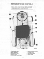
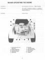
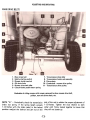
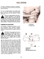
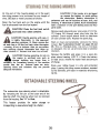
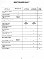
LE FT and RIG HT indicate the left and right sides
of the riding mower when facing forward in the
driver's seat.
The portion
of the machine which carries the
operator is referred to as the RIDER. The housing
under the rider, which does the cutting, is referred
to as the MOWER. The entire machine is referred
to as a RIDING MOWER.
2
This symbol is used to call your attention to
instructions concerning your personal safety. Be
sure to observe and follow these instructions.
Whenever the operator dismounts from the riding
mower or leaves the riding mower unattended,disengage
the mower and shut off the engine.
Know the controls
and how to stop quickly.
READ THE OPERATOR'S
has been supposedly cleared of foreign objects,
small objects may have been overlooked and may
be discharged by the mower causing serious injury.
MANUAL.
C.nly move the gear selector lever to shift into gear
or change gears with the clutch-brake pedal disengaged.
Never place hands or feet under the mower, in the
discharge chute, or near any moving parts while the
mower is running. Do not work on the mower with
the engine running, as the mower could acciden-
Watch out for
roadways.
traffic
when crossing or near
When making any adjustments
to your riding
mower, always disconnect the high tension wire to
the spark plug, otherwise the engine may start
causing serious injury.
tally be engaged and cause injury.
Never leave the engine running unattended or
permit the riding mower to be operated by persons
not acquainted with its use and the rules for safe
operation.
Be sure the mower clutch
control
is "DISENGAGED"
and the transmission
is in neutral
before starting the engine.
Be sure all stones, branches, or other objects that
might be picked up and thrown by the mower
blades are removed before starting to mow.
It is recommended that the machine be stopped
and inspected for damage after striking a foreign
object and that any damage be repaired before
restarting and operating the machine, as broken
pieces could be thrown causing injury.
Never look into the discharge opening while the
blades are in motion as serious accident and/or
injury could result.
Until you become familiar with the riding mower it
is recommended that quick starts, stops, and rapid
engagement of the mower be avoided.
.
Stay alert for holes in terrain and other hidden
hazards which could cause loss of control or upset.
Keep the machine in good operating condition and
keep safety devises in place. Use guards or shields
as instructed in Operator's Manual to avoid injury.
Children should not be allowed to operate the
riding mower unless properly supervised, and are
physically and mentally capable of safe operation
or injury may occur.
The discharge shield on the mower must be
attached at all times while operating the mower.
Avoid sudden stops or starts, especially on steep
slopes to avoid injury.
Disengage power to the mower when transporting
or not in use.
Do not carry passengers or give rides as serious
injury could result.
Before backing the riding mower always look for
obstacles or bystanders in the area where the riding
mower will move.
No one should operate this machine while under
the influence of intoxicants or drugs that impair
the sensesor reactions.
Do not allow anyone in the area parallel to the
discharge opening while moving. Although the area
3
Handle gasoline with care it is highly flammable:
A. Use approved gasoline container.
B. Never
remove the fuel tank cap or fill the fuel tank when
the engine is running, is hot, or indoors. Also, do
not smoke when working around inflammable fuel.
Wipe up spilled gasoline. C. Replace gasoline cap
securely.
NOTE:
system
mower
position
The rider has an interlock safety starting
and the engine will not start unless the
clutch control is in the full disengaged
and the gear selector lever is in neutral.
After the engine starts, slowly move the throttle
control lever to "FAST" position. Do not use the
choke to enrich the fuel mixture, except when
starting the engine.
STARTING THE ENGINE
Keep hands and feet clear of blade and
all moving parts to avoid injury.
Observe the
following
1. Place
clutch-brake
the
procedure
pedal
Pedal
to
start theengine:
The combination clutch-brake pedal is used to
disengage the engine from the transmission when
shifting gears and to actuate the brake to stop therider.
in the lockedposition.
To shift gears while the rider is in motion, pedal
should be depressed approximately 1/2 the travel
distance.
Be sure the spark plug wire is properly attachedto
the spark plug.
Make certain
mower
clutch
position
as shown.
Be sure gear selector
lever is in the"DISENGAGED"
To disengage the clutch, and apply the brake, press
the pedal all the way down.
lever is in "NEUTRAL".
5. Move the throttle control to choke position.
Electric Starting: Turn ignition key clockwise to
the start position and release it as soon as the
engine starts. Do not operate the starter more than
30 seconds at anyone time. If engine does not
start within this time, turn the key off and wait a
few minutes, then try again.
STOPPING THE ENGINE
Electric
and Manual
Starting
(Equipped
with
Ignition
Key): Depress the clutch-brake
pedal to
disengage the transmission. Move the gear selector
lever to "NEUTRAL"
and the mower clutch
control lever to the "DISENGAGE"
position.
After the engine starts, slowly move the throttle
control lever to the "FAST" position. Do not use
the choke to enrich fuel mixture, except when
necessary to start the engine.
Move the throttle control lever to the "SLOW"
position and allow the engine to idle a short time
before stopping. Then turn the ignition key or
switch to the "OFF" position.
Manual Starting (Riding mowers without electric
starting:) If so equipped, turn ignition key clockwise to the "ON" position. Give a quick steady
pull on the recoil starter handle to start the engine.
Do not jerk or pull it out to the very end in a
I:ough manner. Always pull the handle so the rope
is in a straight line through the guide. Maintain
your hold on the handle and allow the cord to
return slowly. Releasing the handle when the cable
is extended will shorten the life of the starter.
Clutch-Brake
2.
3.
4.
Manual Starting (Not equipped with Ignition Key):
Depress the clutch-brake pedal to disengage the
transmission. Move the gear selector lever to
"NEUTRAL"
and the mower clutch control lever
to the "DISENGAGE" position. Move the throttle
control lever to the "OFF" position.
6-
ADJUSTINGAND OPERATING
8e sure blade~ are assembled so the cutting edges
are in the direction of rotation with the wind wings
pointed toward the deck.
Position the mower in the lowest position. Detach
front
of
mower
from
frame
by removing
the
retaining pins from the front mounting brackets.
The pins are held by two quick-attachable cotter
pins.
To detach the blade, place a large wood block
between cutting edge and housing to keep the
blade from rotating. Then remove the jam nut or
cap screws, depending on whether you have a side
discharge or a rear discharge mower.
Slide the mower backward
mower center drive pulley
of mower from I ift frame.
When replacing blades use the reverse procedure,
lexcept put the wood block between the wing of
the blade and the deck.
to remove V-belt from
and to disconnect rear
Raise the mower lift handle to the highest position
and slide the mower out to the side.
HEIGHT OF CUT
Cutting height can be adjusted from approximately
1-1/2-i nches to 4-i nches qu ick Iy and easiIy. The
mower height control lever is located directly
under the operator's seat. When the lever is pulled
out it can be raised or lowered to the desired
cutting height.
The height of cut is approximate since operator
weight and tire inflation will effect the cutting
height.
The cutting blades are designed to create a suction
to I ift the grass for an even cut.
The mower extends beyond the driving wheels to
permit cutting close to walkways, fences, buildings,
trees, etc.
ATTACHING
AND
DETACHING
THE
MOWER
The facilitate changing the blades, sharpening the
blades, cleaning, etc., the mower may be detached
as follows:
CAUTION!
Stop the engine and disconnect the high tension wire to the
spark plug. Lock the brake prior to
leveling the mower.
9-
ADJUSTINGAND OPERATING
ADJUSTING
MOWER
DRIVE
V-BEL T
Raise the mower to the maximum lift position
and turn the wheels a full right and full left. If thecle
between the mower housing and the tires
is less than 1/8-inch, the mower shou Id be moved
back slightly to give clearance.
adjust the mower proceed as follows:
CAUTION! Stop the engine, disconnect
the high tension wire to the spark plug,
and lock the brake before working on
the machine.
REPLACING
1. Place the mower height control
lowest position.
lever in the
MOWER
DRIVE
V-BELT
CAUTION! Stop the engine, disconnect
the high tension wire to the spark plug,
and lock the brake before working on
the machine.
Engagethe mower clutch.
Put a pencil line on the mower housing in front
of the mower front mounting brackets.
Adjust the mower forward by loosening bolts
"c" on the front mounting brackets and sliding the
mower forward until the distance between the
backsides of the belt is 1-1/2-inch at "D".
NOTE: Substitute belts may not be satisfactory.
Use only specified replacements. See your International Harvester dealer.
Place the mower height control lever in the lowest
position and disengage the mower clutch control.
NOTE: The mowe. should be moved forward an
equal distance on cach side (approximately
1/4-inch),
Detach the front of the mower from the lift
assembly to facilitate removal of the belt from the
mower-crankshaft pulley and the mower drivepull
Retighten bolts "C".
installing
a new belt be sure to place belt in
Reconnect the high tension wire to the sparkplug.the upper groove of the mower drive pulley (on the
deck) and in the
crankshaft pulley.
7. Place the mower lift handle in the third position
from the bottom. Start the engine and slowly
engage the mower clutch control. Then, disengage
and check to make sure mower declutches properly. If mower clutch control does not declutch,
shut off the engine, detach the spark plug wire, and
check position of belt guides See page 14. If it still
will not declutch, move mower backward 1/16inch.
8.
To
2.
3.
4.
5.
When
6.
lower
groove
of the
mower-
NOTE: When installing a new belt, make certain
that the belt runs between the pulleys and the belt
guides on the mower drive pulley and the mowercrankshaft pulley. Otherwise a ruined belt will
result, thus requiring early replacement.
12-
ADJUSTINGAND OPERATING
MAIN DRIVE BELTS
1 -Main drive belt
2 -Safety starting switch
3 -Mower clutch control
4 -Oil drain hole
5 -Mower drive belt idler
6 -Clutch-brake pedal return spring
7 -Transmission drive idler
8 -Transmission brake rod assembly
9 -Drive chain
10 -Crankshaft -mower drive pulley
11 -Transmission drive pulley
Underside of riding mower with mower removed to show mower drive belt,
pulleys, rear axle drive chain, etc.
NOTE
II A II -Period
ically check the transm ission
end of the rod to obtain the proper adjustment of
1-1/2-inches. Tighten the nuts relative to each
other until firmly locked together to insure that
they will not loosen up.
brake rod spring. If the spring length exceeds
1-1/2-inches with the brake pedal in the locked
position readjust the locknut and jam nut on the
-13-
ADJUSTINGAND OPERATING
ADJUSTABLE
A
REAR AXLE DRIVE CHAIN
To properly adjust the drive chain set the transmission in neutral, block the front wheels, jack up
the rear end of the rider, and remove the rear
wheels. NOTE: Remember the order in which the
washers are removed from the axle. When reassembling be sure the washers are assembled in the
same order to maintain proper drive chainalig
CAUTION!
Stop the engine, disconnect
the high tension wire to the spark plug,
and lock the brake before working on
the machine.
After 5 hours of operation, or when excessive noise
is noted, check the chain tension.
The drive chain can be adjusted to compensate for
stretch and wear. The rear axle bearing mounting
holes are slotted at the top to move the axle back
for proper adjustment as shown.
A
Be sure machine
to avoid injury.
is adequately
Adjust the bearing housings until the slack is out of
the chain. The chain must not be taut. If the drive
chain is too tight, excessive wear and stretch will
result in premature failure. Not enough tension
may allow chain to jump the sprocket, ride the
teeth, break, or whip excessively. Axle must be
perpendicular to side of rear frame. Adjust each
side an equal amount. Tighten nuts to 33-37 ft.-lbs.
blocked
-16-
This engine is designed to operate on unleaded or
low lead gasoline with a 91 minimum octane rating
(Research Method),
The use of unleaded gasoline will lengthen spark
plug and valve life, maintain engine performance
longer, and reduce rust and corrosion
of engine
while stored.
A
CAUTION! Handle gasoline with care, it
is highly flammable: A. Use approved
gasoline container. B. Never remove the
fuel tank cap or fill the fuel tank when the engine
is running, is hot, or indoors. Also, do not smoke
when working around flammable fuel. Wipe up
spilled gasoline. C. Replace fuel tank cap securely.
CARBURETOR
1 -Carbu retor
2 -Fuel shut-off
ADJUSTMENTS
The carbu retor is adjusted at the factory. Do not
make adjustments unless absolutely necessary.
Factory settings are correct for normal operating
conditions. If adjustments are necessary proceed as
follows:
A
CAUTION!
the
engine
During
in
operating
confined
do
area
not
such
run
as
storage building any longer than is
necessary for immediate moving of the machine
ouside into the air. Exhaust gases are toxic.
Opening doors and windows may not provide
adequate ventilation.
Start the engine and allow it to warm up at 3000
RPM. Turn needle valve in until engine misses (lean
mixture) then turn it out past smooth operating
point until engine runs unevenly (rich mixture).
Turn needle valve to the mid-point between rich
and lean so engine runs smoothly. Hold throttle at
idle position and set idle speed, adjusting screw
until engine idle speed is 1800 RPM. Hold throttle
at idle position and turn idle valve in (lean) and out
(rich) until engine idles smoothly. If necessary,
correct idle speed. Release the throttle -engine
should accelerate without hesitation or sputtering.
If engine does not accelerate properly, the carburetor should be readjusted, usually to a slightly
richer mixture of needle valve.
1 -Needle valve
2 -Idle valve
3 -Idle speed adjusting screw
-17-
The battery is located under the operator's seat. To
service or replace the battery remove the seat.
Remove the wing nut located under the center
backrest of the seat. Lift the back of the seat and
pull back to remove seat from front slot of seat
mounting bracket.
Occasionally remove the battery cables and brighten
the terminal contact surfaces with wire wool, and
reassemble. Apply a light coat of vaseline or chassis
lubricant. Be sure terminals are clamped tightly,
the rubber cover is slid over the positive terminal,
and that battery is fastened securely in the battery
box. Replace defective cable, and keep vent holes
in battery filler caps open.
When reinstalling operator's seat reverse the above
procedu reo
The output of the built in charging circuit in the
engine rises from 2 amperes at 2400 RPM to 3
amperes at 3600 RPM and uses less than .2
A
CAUTION! If the tractor is to be tipped
up or on its side remove the batteries to
avoid spilling the electrolyte. Battery
electrolyte is poisonous and can be injurious to
eyes, skin, and clothing. If electrolyte is spilled,
flush immediately with a solution of one part
baking soda to four parts water.
horsepower.
Connecting Booster Batteries
When required, a booster 12-volt battery may be
connected in parallel with the 12-volt system on
the tractor.
NOTE: All circuits must be turned "off",
Electrical
System
is Negative
(-) grounded
only,
Reversed polarity will result in permanent damage
to components of the electrical system.
A
BATTERY
For long battery life and trouble-free operation
check the battery at 15-day intervals for water
level. If the battery is in need of charging, it should
be given immediate attention. Keeping the battery
fully charged not only adds to its life but makes it
available for instant use when needed.
solutions,
Electrical
storage
inflammable
batteries
hydrogen
gas
see your
SPARK PLUG
NOTE: Remove
before removing.
CAUTION!
Acid or electrolyte
should
never be added except by a skilled
battery
man. Under no circumstances
"dopes",
highly
For
dependable
battery
service,
International Harvester dealer.
The electrolyte (acid and water) in each cell should
be at the proper level at all times to prevent
battery failure. When the electrolyte is below this
level, pure, distilled water should be added.
add any special battery
powders.
ION!
off
when charging and continue to do so for
some time after receiving a steady charge. Do not
under any circumstances allow an electric spark or
an open flame near the battery. Do not lay tools
across battery terminals as this may result in a
spark or short circuit which may cause an explosion. Be careful to avoid spilling any electrolyte
on hands or clothing.
Liquid Level
A
CAUT
give
or
-18-
all dirt from
base of spark plug
ELECTRICALSYSTEM
Remove the spark plug after every 100 hours of
operation for cleaning and checking the gap. When
adjusting the gap, always bend the outer electrode.
Never bend the insulator. If gap between the
electrodes is too great, the engine will misifre and
be hard to start.
NOTE: Do not use abrasive cleaning machine;
because any grit introduced into the engine could
cause severe damage.
Always use a spark plug wrench when removing or
reinstalling the plug.
Be sure the gasket is in good condition, and screw
plug in tightly. Do not tighten more than enough
to compress the gasket to seat the plug and assure a
good heat transfer between the plug and cylinder
head.
Replace defective
plug with
new plug. Use a
Champion CJ-8 spark plug or equivalent. See your
International
Harvester dealer for a correct replacement plug.
Cleaning Spark Plug
Clean spark plug with a pen knife or wire brush
and solvent.
If electrode
is burned away or the
porcelain is cracked, replace with new plug.
ENGINE COOLING
This is an air cooled engine. Air must circulate
freely around the engine. Keep the cooling fins and
housing area free of accumulated dirt and trash or
engine will overheat and result in damage to
moving parts.
OIL FOAM AIR CLEANER
Clean and re-oil the air cleaner element every 25
hours under normal operating conditions. Under
extremely dusty conditions, clean the element
every few hours.
Checking the spark plug gap.
Set gap at .O30-inch.
Remove the cover screws, lift the air cleaner cover
and carefully remove the element to prevent dirt
from entering the carburetor.
Wash the foam element in kerosene or liquid
detergent and water to remove all dirt. Also clean
the air cleaner body and cover.
Wrap the foam element in a cloth and squeeze dry.
Then, saturate the element in engine oil (SAE-30).
Squeeze the element to remove excess oil and
reassemble and fasten to carburetor with screw.
NOTE: Replace air cleaner mounting gaskets that
are worn or damaged, to prevent dirt or dust
entering engine through improper sealing.
To clean the element, proceed as follows:
19-
At the end of the mowing season or in the event
the riding mower is to be stored for any length of
time, (30 days or more) proceed as follows:
Drain the fuel tank and run the engine until the
fuel is exhausted from the fuel system.
Drain the fuel tank out-ofdoors and into a clean container.
CAUTION! Handle gasoline with care, it
is highly flammable. A. Use approved
gasoline container. B. Never remove the
fuel tank cap or fill the fuel tank when the engine
is running, is hot, or incloors. Also, do not smoke
when working around flammable fuel. Wipe up
spilled gasoline. C. Replace fuel tank cap securely.
A
CAUTION!
the
engine
During
in
operating
confined
do
area
not
such
run
as
storage building any longer than is
necessary for immediate moving of the machine
ouside into the air. Exhaust gases are toxic.
Opening doors and windows may not provide
adequate ventilation.
CAUTION! If the tractor is to be tipped
up remove the battery to avoid spilling
the electrolyte. Battery electrolyte is
poisonous and can be injurious to eyes, skin, and
clothing. If electrolyte is spilled, flush immediately
with a solution of one part baking soda and four
parts water.
Remove spark plug and pour one ounce of I. H. No.
1@ Engine Oil through spark plug hole into thecylind
Crank engine several times to distribute
oil over cylinder walls. Replace the spark plug.
Wash or clean and completely lubricate the riding
mower. See "lubrication
Guide" on pages 23 and
24. This is a fiberglass body. Use only a mild soap
or detergent. Do not use ammonia base or abrasive
cleansers.
Remove the battery and place it in a cool, dry
place above freezing (+320 F.). Check the battery
at least once a month for water level and amount
of charge.
Store your riding mower in a dry and protectedplace
Leaving the riding mower outdoors, exposed
to the elements, will result in materially shortening
its life.
automotive type steering wheel is detachable.
By removing the roll pin at the lower end of thesteering
shaft the steering wheel can be removedfrom
the housing. See "A" in illust.
This feature provides for easier storage or
transporting in areas where height is a factor.
CAUTION!
The
20-
ENGINE Oil
NOTE:
After checking the oil the oil dip stick
must be fully seated in the filler tube to avoid
excessive oil consumption
and irregular engine
operation.
To aid starting, the selection of crankcase lubricating oils should be based on the lowest
anticipated temperature until the next drainperiod.
After the first five hours of operation, change the
oil as directed in Lubrication Table. The engine oil
must be drained and replaced with new oil every 25
hours of engine operation thereafter,
or a
minimum of once a year, and sooner if the
equipment is operated under extremely dusty
conditions.
Check the oil level of the engine crankcase every
five hours to see that it is filled to the correct level.
Check the oil level only while the engine is
stopped.
The crankcase oil filler cap has the oil level gauge
attached to it. Always keep the oil level between
the "FULL"
and "ADD"
marks in the "SAFE"
range on the gauge. Do not over-fill.
When
checking
the
oil
level, the gauge must be
withdrawn
and wiped clean, then inserted all the
way and withdrawn for a true reading.
recommend I.H. No.1 Engine Oil. If other than
I.H. No.1 Engine Oil is used, it must be designated
"For Service MS". In new API code these oils are
usually
designed as meeting
either SO or SE
requ irements.
We
1.
2.
3.
4.
5.
After Every 5 Hours of Operation
Oil filter cap and
Bayonet-type Oil
Level Gauge
See Page5.
Check the oil (with the engine stopped) and add sufficient new
oil to bring it to the "FU LL" mark on the gauge. Do not
\ over-fil'. Do not operate the engine if the oil level is below the
"ADD" mark on the gauge. Dip stick must be fully seated
, before operating the engine.
After Every 10 Hours of Operation
Rear Axle Drive Chain
See Page 16.
Pedal Return Spring
SeePage13.
Mower Idler Pulley Arm
See Page 15.
Rear Axle Bearings (2)
See Page 16.
f Apply
a light coat of engine oil to the full
length of the chain.
Apply a few drops of oil to the spring.
Apply a few drops of oil to the idler pulley arm.
Use IH 251 H EP grease or equivalent No.2 multi-purpose
lithium grease and apply two or three strokes of the lubricator
to grease fittings.
-21-
LUBRICATION GUIDE
Afer Every 10 Hours of Operation -Continued
Front Wheels
Use IH 251 H EP grease or equivalent No.2 multi-purpose
lithium grease and apply one or two strokes of the lubricator to
the grease fittings (one fitting on each front wheel).
Mower Spindle
Bearings (3)
Rear Discharge
Mower
See Page 15.
Use IH 251 H EP grease or equivalent No.2 multi-purpose
lithium grease and apply one or two strokes of the lubricator to
the grease fittings (one fitting on each spindle). Center spindle
can be greased through lift handle slot.
After Every 25 Hours of Operation
While the engine is warm remove the drain plug and drain all the
oil from the crankcase. To drain completely, raise the right side
of the riding mower by placing a 4-inch to 6-inch block under the
right rear wheel. After draining, replace the drain plug. Remove
the crankcase oil filler cap and refill the crankcase with new oil
up to the "FU LL" mark on the oil level gauge. Refer to the
"Lubrication
Table" for proper quantity and viscosity to use.
Engine Crankcase
See Page 13.
Mower Spindle
Bearings (3)
Side Discharge
Mower
See Page 15.
Use IH 251H EP grease or equivalent No.2 multi-purpose
, lithium grease and apply one or two strokes of the lubricator to
the grease fittings (one fitting on each spindle). Center spindle
, can be greased through lift handle slot.
Check
Point of Lubrication
at
Hours
Change
Anticipated
Hours
+320 F.
32 oz.
Crankcase
5
25
qt.
Transmission and
Differential
6.
7.
8.
9.
Above
Engine
1
Air Temperature
at
+320 to 00 F.
I. H. No.1 @
I.H. No.1 (!)
Engine Oil
SAE-30
Engine Oil
SAE-10W
Below
SAE-5Wor
SAE-5W-20
Factory sealed. See your ,. H. Dealer
22-
00 F.
with
No accident-prevention program can be suc-
industrial plant, can be safer than the man who
cessful without the wholehearted co-operation
is at the controls.
of the person who is directly responsible for the
vented-and
operation of equipment.
done by the operators who accept a full measure
To read accident reports from allover
the
If accidents are to be pre-
they can be prevented-it
will be
of their responsibility.
country is to be convinced that a large number
It is true that the designer, the manufacturer,
of accidents can be prevented only by the
the safety engineer can help; and they will help,
operator anticipating
but their combined efforts can be wiped out by
the result before the
accident is caused and doing something about
a single careless act of the operator.
it.
It is said that' 'the best kind of a safety
device is a careful operator. II We ask you
No power-driven equipment, whether it be
transportation or processing, whether it be on
the highway, in the harvest field or in the
be
to be that kind of an operator.