1
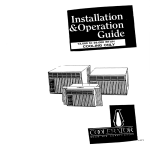
ELECTRIC
SELFCLEANINGSET-INUNIT
WITHCONVERTIBLETOP
-
-
Part No. 13199991868842
Rev. A
FOR CUT-OUT DIMENSIONS
SEE FRONT AND
TOP VIEWS OF
CABINETS BELOW.
ELECTRIC
SUPPLY JUNCTION
BOX. LOCATE ON
FLOOR OR ON WALL NEAR FLOOR LINE, IN ADJOINING CABINETS.
CAUTION:
To eliminate
the hazard of reaching
over
heated surface units, cabinet storage space located
above the surface units should be avoided. If cabinet
storage IS to be provided, the hazard can be reduced by
lnstalllng a range hood that projects horizontally
a minimum of 5 inches beyond the bottom of the cabinet.
,-WALL
LINE
A
22-518” /
.--I
TO
CABINET
FRONT
29” -
I
-23”
CABINET ‘p
FRONT
_I ------ /
-- - TOP VIEW
OF COUNTER TOP
l-114” MAX.
-f
CABINET TOP
/
f
i--I
29”
314” MIN. I
1
MIN.
FLOOR LINE El:
b
0
“A” = 30” MIN. CLEARANCE
BETWEEN TOP OF THE
COOKING PLATFORM AND THE BOTTOM OF AN
UNPROTECTED WOOD OR METAL CABINET.
“A” = 24” MIN. WHEN BOTTOM OF WOOD OR METAL
CABINET IS PROTECTED
BY NOT LESS THAN
V4”
ASBESTOS
MILLBOARD
COVERED
WITH
NOT LESS THAN NO. 28 MSG. SHEET STEEL,
0.015” STAINLESS STEEL, 0.024” ALUMINUM OR
0 020” COPPER
NOTES:
1. Product hangs from burner box flange over countertop and is secured by four screws through
front
frame into cabinets.
is installed
in a countertop
with a
2. When product
formed front edge, it may be necessary to “shave” it
to the flat area height of countertop and the width held
to the 30” dimension. (See sketch.)
1
FRONT VIEW
FIGURE 1
1. GENERAL
The rnstallation must conform to any local codes. Remove
all cords, tape and wire used to hold various parts in
positron during transportatron.
COUNTER TOP (FORMED OR SQUARE EDGE)
\
NOTE: FIT BACK OF
COUNTER TOP TIGHT
TO WALL.
2. CARPENTRY
Prepare the cutout space, shown in Figure 1. in the
desired location in the countertop
and cabinet. Note
countertop to cabrnet face mounting dimension in Figure
2. Install 1” x 2” braces as shown in Figure 2 on both sides
of cutout to prevent any sag of countertop. All dimensions
In Figures 1 and 2 must be adhered to, and adjoining
cabinets
must be plumb and level before attaching
countertop to cabinets.
i” X 2” BRACE
ORAihcERw
FRONT
CABiNET
UNDERSIDE
SCREWED ToOF
COUNTER TOP
FIGURE 2
(Contrnued)
3. ELECTRICAL
REQUIREMENTS
OBSERVE
ALL
ORDINANCES
GOVERNING
CODES
CAUTION: If connecting
to a four-wire electrical system
(mobile home) the appliance frame MUST NOT be connected to the neutral wire of the four-wire electrical system. Separate the white and green wires that extend out
of the end of the supply cable of the appliance. Connect
the white, red and black wires from the supply cable,
matching the colors, to the corresponding
wires in the
junction box. Connect the green wire from the supply
cable to the ground wire in the junction box.
AND
SAVE THESE INSTRUCTIONS
FOR THE
LOCAL ELECTRICAL
INSPECTOR’S
USE.
A. A three-wire or four-wire single phase 1201240 Volt,
60 Hz AC only electrical
supply (or three-wire or fourwire 1201206 Volt is specified on nameplate) is required
on a separate circuit fused on both sides of the line
(time-delay
fuse or circuit breaker is recommended)
DO NOT fuse neutral. The fuse size must not exceed the
circuit rating of the appliance specified on the nameplate.
GROUNDED COLD
WATER PIPE
(REMOVE PAINT, ETC.)
COPPER
GROUND WIRE
NOTE: Wire sizes and connections must conform with the
fuse size and rating of the appliance in accordance
with
the National Electrical Code and local codes and ordinances. Do not use an extension cord.
EN
FIRMLY
6. The appliance should be connected to the fused disconnect (or circuit breaker) box through flexible armored
or non-metallic
sheathed cable. The flexible armored
cable extending from the appliance should be connected
directly to the junction box. The junction box should be
located as shown in Figure 1 so as much slack as possible
remains in the cable between the box and the appliance
so it can be moved if servicing is ever necessary.
C. A suitable strain relief must be provided
power supply cord to the junction box.
GROUND CLAM
~NU;ST;; TIGHT
FIGURE 3
*Cold water
ground and
electrically
or pump)
connections.
to attach the
4. ELECTRICAL
CONNECTION
It is the personal responsibility
and obligation
of the
customer to contact a qualified installer to assure that the
electrical installation
is adequate and is in conformance
with the National
Electrical
Code and local code
ordinances.
ELECTRICAL
APPLIANCE.
GROUND
IS REQUIRED
pipe must have metal continuity to electrical
not be interrupted by plastic, rubber or other
insulating connectors (Including water meter
without
adding
a jumper
wire at these
5. INSTALLATION
Insert
appliance
into cut-out.
Screws
are provided
for
fastening
the appliance
to the counter
top. The mounting
bracket holes in the hanger bracket may be used as a template to locate the four appliance
mounting
screw holes.
ON THIS
This appliance
is equipped
with copper lead wires. If
connection
is made to aluminum house wiring, use only
special connectors which are approved for joining copper
and aluminum
wires in accordance
with the National
Electrical Code and local codes and ordinances.
NOTE: It may be helpful to remove the Oven Door when
installing the oven in the cut-out. Refer to the instructions
on page 4 for removing the Oven Door.
This appliance
is manufactured
with a white neutral
power supply wire and a frame connected green ground
wire.
A. If local codes permit connection of the frame qroundinq conductor
to the neutral (white wire), connect the
green and white wire from the supply cable of the appliance together and to the neutral (white) wire in the junction box. Connect the remaining wires from the supply
cable, matching colors to the wires in the junction box.
Next remove the burner
place.
modulars
and set them in a safe
Then remove the four screws that secure
frame to the range. See Figure 4.
6. If used in mobile home or if local codes DO NOT permit frame qroundinq
to the neutral, separate the white
and green wires that extend out of the end of the supply
cable of the appliance. Connect the white wire from the
supply cable to the neutral wire. Connect the black and
red wire from the supply cable, matching the colors, to the
corresponding
wires in the junction box. The green wire
must now be used to ground the appliance in accordance
withlocal
electrical codes. Connect the insulated green
colored copper ground wire to a grounded cold water
pipe* or to the grounded lead in the service panel. Do not
qround to a gas supply pipe. Do not connect to electrical
power supply until appliance is permanently
grounded.
Connect the ground wire before turning on the power
(see Figure 3).
FIGURE 4
3
the cooktop
6. OVEN DOOR REMOVAL
Lift the cooktop frame
shown in Figure 5.
up at the front
and support
Open Oven
at sides, lift
hinge arms
in at bottom
as
Use the four mounting
bracket holes in the hanger
brackets
as templates
to locate the four appliance
mounting screw holes. See Figure 5.
TO
Door to broil position. Grasp the door firmly
up and away from the range. To replace, slip
into door slots. With hand or knee, push door
until it clicks. Then close door (see Figure 6).
REMOVE
I
r
FIGURE 6
7. CHECKING
CONTROLS
OVEN
CAUTION: Do not touch the elements.
and you may ger burned.
They may be hot
Preheat-Turn
the Oven Selector
Knob to “Preheat”
and set the Oven Temperature
Knob to 350°F. Both the
Upper and Lower Oven Elements should become red and
the Signal Light should glow. When the oven reaches
the desired temperature,
the light will go out.
Bake-After
the oven is “Preheated”
set the Oven Selector Knob to “Bake”. The Oven Selector Light is designed
to turn on and off during baking as the Bake Element
cycles on and off.
.
Broil-Turn
the Oven Selector Knob to “Broil” and set
the Oven Temperature Knob to “Broil”. The Top Element
should become red and the Signal Light should glow.
I,
\
MOUNTING SCREWS
P-EACH SIDE
CLOCK
Refer to the Use and Care Guide for proper
the clock.
FIGURE 5
operation
of
SERIAL PLATE LOCATION
CAUTION: For your personal safety, and to minimize
potential
personal injury, the range must be securely
fastened to the cabinet, using the four screws that are
provided.
The Serial Plate is located
oven front frame.
on the upper left corner of the
BEFORE YOU CALL
FOR SERVICE
Check to make sure the house fuses or circuit
for your oven are not blown or open.
In the event Your WHIRLPOOL
apphance
should need e.erwce. call the dealer from whom You
purchased
the appt~ance or a WHIRLPOOL
franchised
TECH-CARE@serwce
company
He is in the
Yellow Pages of your telephone
dlrecrory
INsted under Washers,
Dryers-Repairing
or Serwclng.
You can also obtain his name and number
by daalang. free. wthln
the continental
Umted States
(except Alaska) rha Whirlpool
COOL-LINE@Sewa
(BOO) 253.1301 lwhen csllmg from Machlgan.
dial (800) 632.2243;
from Alaska or Hawaii,
dial (600) 253.1121 i. Dial lust es You normally
dial
long distance.
A speaal operator
wll tell You the name and number
of your nearest Whirlpool
TECH-CARE
serwce outlet. Dunng
normal
worknng
hours, Whirlpool
consultants
at this same
numberwll
also answer any questions
about operating
or malntafmng
your appliance
not covered
InvourOperating
lnstruct~ons
Learn the benefits of using
your WHIRLPOOL apphance.
.
-.
---.
WHIHLPUUL
------
TECH-CARE
.-.-..
CURPURArlUN
serwce
for malntalni,ng
--_.--_.
BtN
4
1 UN
..-
the quahty
^^-
HAHtlUti,
originally
_..^...^
MlCl-llbAN
built
__.
unto
_^^^-
4YUZZ
1
breaker