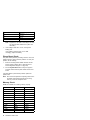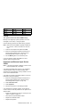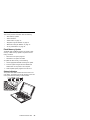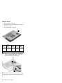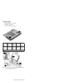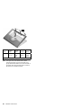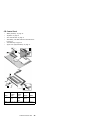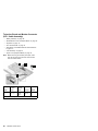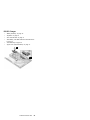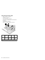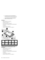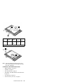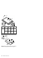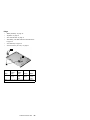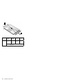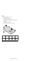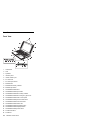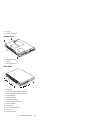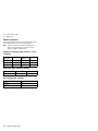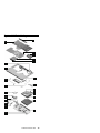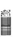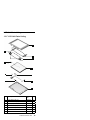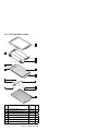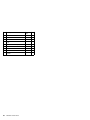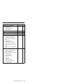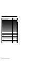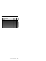
1
IBM Mobile Systems ThinkPad i Series 1400 (2611) This Manual Supports The Following Models: 1412, 1419, 1452, 1456, 1459, 1472, 1476, 1479, 140A, 140C, 140F, 140H, 140K, 140L, 140M, 140T, 143C, 143H, 143K, 143L, 143M, 143T, 147A, 147F, 147A, 149C, 149F, 149H, 149K, 149M, 149T, Hardware Maintenance Manual May 1998 S37L-5192-00 Before using this information and the product it supports, be sure to read the general information under “Read This First” on page 1. First Edition (May 1999) The following paragraph does not apply to the United Kingdom or any country where such provisions are inconsistent with local law: INTERNATIONAL BUSINESS MACHINES CORPORATION PROVIDES THIS PUBLICATION "AS IS" WITHOUT ANY WARRANTY OF ANY KIND, EITHER EXPRESS OR IMPLIED, INCLUDING, BUT NOT LIMITED TO, THE LIMITED WARRANTIES OF MERCHANTABILITY OR FITNESS FOR A PARTICULAR PURPOSE. Some states do not allow disclaimers or express or implied warranties in certain transactions; therefore, this statement may not apply to you. This publication could include technical inaccuracies or typographical errors. Changes are periodically made to the information herein; these changes will be incorporated in new editions of the publication. IBM may make improvements or changes in the products or the programs described in this publication at any time. Requests for technical information about IBM products should be made to your IBM Authorized Dealer or your IBM Marketing Representative. Copyright International Business Machines Corporation 1999. All rights reserved. Note to US Government Users — Documentation related to restricted rights — Use, duplication, or disclosure is subject to restrictions set forth in GSA ADP Schedule Contract with IBM Corp. Contents ThinkPad i Series 1400 Hardware Maintenance Manual . . . . . . . . . . . . . . . . . . . Read This First . . . . . . . . . . . . . . . . How to Use Error Messages . . . . . . . . How to Diagnose Multiple FRUs . . . . . . What to Do First . . . . . . . . . . . . . . Screw Notices . . . . . . . . . . . . . . . Power-On and Setup Password . . . . . . . . Check Procedures . . . . . . . . . . . . . . Power Systems Check . . . . . . . . . . . Planar Board Check . . . . . . . . . . . . Memory Check . . . . . . . . . . . . . . Keyboard and External Input Device Check . Audio Function Check . . . . . . . . . . . TrackPoint IV Check . . . . . . . . . . . . Diskette Drive Check . . . . . . . . . . . . CD-ROM/DVD-ROM Drive Check . . . . . . Modem Board Check . . . . . . . . . . . BIOS Utility . . . . . . . . . . . . . . . . . . Navigating the BIOS Utility . . . . . . . . . Power Management Features . . . . . . . . . Screen Blanking Mode . . . . . . . . . . . Standby Mode . . . . . . . . . . . . . . . Hibernation Mode . . . . . . . . . . . . . Symptom-to-FRU Index . . . . . . . . . . . . Numeric Error Codes and Messages . . . . Beep Symptoms . . . . . . . . . . . . . . No Beep Symptoms . . . . . . . . . . . . Keyboard/TrackPoint-Related Symptoms . . LCD-Related Symptoms . . . . . . . . . . Indicator-Related Symptoms . . . . . . . . Power-Related Symptoms . . . . . . . . . Memory-Related Symptoms . . . . . . . . Audio-Related Symptoms . . . . . . . . . PC Card (PCMCIA)-Related Symptoms . . . Power Management-Related Symptoms . . . Peripheral-Device-Related Symptom . . . . Modem-Related Symptoms . . . . . . . . . Intermittent Problems . . . . . . . . . . . Undetermined Problems . . . . . . . . . . Related Service Procedures . . . . . . . . . . Flash Memory Update . . . . . . . . . . . Status Indicators . . . . . . . . . . . . . . Power Switch . . . . . . . . . . . . . . . Diagnostic Program Diskette . . . . . . . . Maintenance Program Diskette . . . . . . . Fn Key Combinations . . . . . . . . . . . Product Overview . . . . . . . . . . . . . . . FRU Removals and Replacements . . . . . . . Before FRU Removals and Replacements . . . . . . . . . . . . . . . . . . . . . . . . . . . . . . . . . . . . . . . . . . . . . . . . . . . Contents . . . . . . . . . . . . . . . . . . . . . . . . . . . . . . . . . . . . . . . . . . . . . . . . . 1 1 1 1 2 3 4 5 6 8 8 9 10 10 11 11 12 13 14 15 15 15 16 17 17 19 19 20 20 22 22 22 23 23 23 24 25 25 25 27 27 27 29 29 30 32 33 34 35 iii Battery Assembly . . . . . . . . . . . . . . . DIMM and DIMM Cover . . . . . . . . . . . . Modem Board Cover and Modem Board . . . . Keyboard . . . . . . . . . . . . . . . . . . . CPU Thermal Plate . . . . . . . . . . . . . . RTC Battery, CPU EMI Shield and Hard Disk Drive PCMCIA Holder . . . . . . . . . . . . . . . . LCD Assembly . . . . . . . . . . . . . . . . . Upper Cover (Keyboard Bezel) . . . . . . . . . CD Control Card . . . . . . . . . . . . . . . . Trajection Board and Modem Connector (RJ11 Cable Assembly) . . . . . . . . . . . . . . . DC/DC Charger . . . . . . . . . . . . . . . . Audio PCB and S-Video PCB . . . . . . . . . . Audio Cable and Speaker Cable . . . . . . . . Audio Connector Board . . . . . . . . . . . . Fan Assembly . . . . . . . . . . . . . . . . . Diskette and CD-ROM/DVD-ROM Drives Assembly Planar Board . . . . . . . . . . . . . . . . . LCD Front Cover (12.1-inch) . . . . . . . . . . LCD Front Cover (14.1-inch) . . . . . . . . . . Locations . . . . . . . . . . . . . . . . . . . . . Front View . . . . . . . . . . . . . . . . . . Bottom View . . . . . . . . . . . . . . . . . . Rear View . . . . . . . . . . . . . . . . . . . Switch Locations . . . . . . . . . . . . . . . . System Unit Parts Listing . . . . . . . . . . . . . LCD Unit Parts Listing . . . . . . . . . . . . . . . 12.1" LCD Unit Parts Listing . . . . . . . . . . 14.1" LCD Unit Parts Listing . . . . . . . . . . Miscellaneous Parts . . . . . . . . . . . . . . . . Telephone/Modem . . . . . . . . . . . . . . . . Power Cord . . . . . . . . . . . . . . . . . . . Notices . . . . . . . . . . . . . . . . . . . . . . Trademarks . . . . . . . . . . . . . . . . . . . iv ThinkPad i Series 1400 36 37 38 39 41 42 44 45 47 49 50 51 52 53 55 56 57 60 61 66 72 72 73 73 74 75 79 79 81 83 84 85 86 86 ThinkPad i Series 1400 Hardware Maintenance Manual Read This First Before you go to the check procedures, be sure to read this section. Important Notes Only certified trained personnel should service the computer. Read the FRU service procedures before replacing any FRUs. Be extremely careful during write operations such as copying, saving, or formatting. Drives in the computer that you are servicing might have been rearranged or the drive startup sequence might have been altered. If you select an incorrect drive, data or programs could be overwritten. Ensure that you replace FRUs with the appropriate model. When you replace the FRU, make sure that the model of the machine and FRU part number are correct by referring to the part list. FRUs should not be replaced because of a single, unreproducible failure. Single failure can occur for a variety of reasons that have nothing to do with a hardware defect, such as: cosmic radiation, electrostatic discharge, or software error. FRU replacement should be considered only when a recurring problem exists. In this case, clear the error log and run the test again. Do not replace FRUs if log errors do not reappear. Be careful not to replace a non-defective FRU. How to Use Error Messages Use the error codes displayed on the screen to diagnose failures. If more than one error code is displayed, begin the diagnosis with the first error code. The cause of the first error code can result in the other false error codes being displayed. How to Diagnose Multiple FRUs If the adapter or device has more than one FRU, the error code could be caused by either FRU. Before replacing multiple FRUs, try removing or exchanging each FRU one by one in the designated sequence, to see if the symptoms change. ThinkPad i Series 1400 1 What to Do First The servicer must include the following in the parts exchange form or parts return form that is attached to the returned FRU: 1. Name and phone number of servicer. 2. Date of service. 3. Date when part failed. 4. Date of purchase. 5. Failure symptoms, error codes appearing on display, and beep symptoms. 6. Procedure index and page number in which failing FRU was detected. 7. Failing FRU name and part number. 8. Machine type, model number and serial number. 9. Customer's name and address. Before checking problems with the computer, determine whether or not the damage applies to the warranty by referring to the following: Note for Warranty: During the warranty period, the customer may be responsible for repair costs if the computer damage was caused by misuse, accident, modification, unsuitable physical or operating environment, or improper maintenance by the customer. The following list provides some common items that are not covered under warranty and some symptoms that may indicate the system was subjected to stresses beyond normal use: The following is not covered under warranty: LCD panel cracked by applying excessive force or by being dropped. Scratched (cosmetic) parts. Cracked or broken plastic parts, broken latches, broken pins, or broken connectors caused by excessive force. Damage caused by liquid spilled into the system. Damage caused by improperly inserting a PCMCIA card or installation of an incompatible card. Diskette drive damage caused by pressing the diskette drive cover or inserting diskettes with multiple labels. Damaged or bent diskette drive eject button. CD-ROM/DVD-ROM drive damage caused by excessive force, shock, or by being dropped. Fuses blown by attaching a nonsupported device. Forgotten computer password (making computer unusable). 2 ThinkPad i Series 1400 If the following symptoms are present, they may indicate damage caused by non-warranted activity: Missing parts may be a symptom of unauthorized service or modification. HDD spindles can become noisy if subjected to excessive force or by being dropped. Screw Notices The computer uses special nylon-coated screws with the following characteristics: They maintain tight connections. They do not easily come loose, even with shock or vibration. They need additional force to tighten. They should be used only once. Do the following when you service the machine: Keep the screw kit (P/N 05K4841) in your tool bag. Always use new screws if you are instructed. Use a torque screwdriver if you have one. Loose screws can cause a reliability problem. The IBM ThinkPad computer addresses this problem with nyloncoated screws. Tighten screws as follows: Plastic to plastic Turn an additional 90 degrees after the screw head touches the surface of the plastic part. Logic card to plastic Turn an additional 180 degrees after the screw head touches the surface of the logic card. Torque driver If you have a torque driver, refer to the "Torque" column with each step. Make sure you use the correct screw, and tighten all screws firmly to the torque shown in the table if you have a torque screwdriver. Never use a screw that you removed. Use a new one. Make sure the screws are tightened firmly. ThinkPad i Series 1400 3 Power-On and Setup Password To clear a password from the system, first identify the system password switch by referring to “Switch Locations” on page 74, then follow these steps: 1. Turn off the computer. 2. Unplug the AC Adapter and remove the battery. 3. Remove the keyboard by referring to “Keyboard” on page 39, and the thermal plate by referring to “CPU Thermal Plate” on page 41. 4. Move the password switch (SW3, switch 4) from OFF to ON to bypass the password. Note: SW2 has four switches. Its switch 4 is the password bypass/check switch. Turning the switch to the ON position is "bypass password"; the OFF position is "check password". Refer to “Switch Locations” on page 74. 5. Plug in the AC adapter and turn on the system. 6. While the ThinkPad logo is being displayed, wait for a beep before pressing F1 to enter the BIOS Utility. 7. Select "System Security" from the BIOS Utility main menu and press Enter. 8. Set the "Power-On Password" setting to "None" to clear the password. 9. Save and exit the BIOS Utility. 10. Turn off the system and unplug the AC Adapter. 11. Move the password switch from ON to OFF to enable the password function. 12. Reinstall the thermal plate and keyboard. 13. Reinstall the battery pack and plug in the AC Adapter. To use the password function again, enter the BIOS Utility and set a password. 4 ThinkPad i Series 1400 Check Procedures Use the following procedure as a guide for computer problems. Notes: 1. The diagnostic tests are intended to test only IBM products. Non-IBM products, prototype cards, or modified options can give false errors and invalid system responses. 2. Some test items require tools as shown below: Audio wrap cable (P/N: 65G5180) FDD: Erasable 2HD diskette Parallel: Wrap plug (P/N: 72X8546) Parallel: Test cable (P/N: 05K2580) Serial: Wrap plug (P/N: 72X8546) PCMCIA: PC test card (P/N: 35G4703) CD-ROM/DVD-ROM: Any data and audio CDs Screwdriver kit (P/N: 95F3598) Screwdriver kit (P/N: 05K4693) Torque screwdriver (P/N: 05K4695) 5mm socket wrench (P/N: 05K4694) ThinkPad i Series 1400 Diagnostics Diskette (3 diskette pack, P/N: 09N1020) ThinkPad i Series 1400 Maintenance Diskette (P/N: 09N1025) 1. Obtain the failing symptoms in as much detail as possible. 2. Verify the symptoms by attempting to recreate the failure by running the diagnostic test or by repeating the same operation. 3. Use the following table with the verified symptom to determine which page to go to. Search the symptoms column and find the description that best matches your symptom; then go to the page shown in the "Go to" column. Symptoms (Verified) Go to Power failure. (The power-on indicator does not go on or stay on.) “Power Systems Check” on page 6, then use table in “Power-Related Symptoms” on page 22. POST does not complete. No beeps or error codes/messages are indicated. “Symptom-to-FRU Index” on page 17, then use table in “No Beep Symptoms” on page 19. POST detected an error and displayed numeric error code with error message. “Symptom-to-FRU Index” on page 17. ThinkPad i Series 1400 5 Symptoms (Verified) Go to Other symptoms Appropriate check instructions in this section, then use appropriate tables in “Symptom-to-FRU Index” on page 17. Power Systems Check To verify the symptom of the problem, power on the computer using each of the power sources as follows: 1. Remove the battery pack, diskette drive, and hard disk drive. 2. Connect the AC Adapter and check that power is supplied. 3. Install the diskette drive or hard disk drive one at a time, and check that power is supplied from each power source. If you suspect a power problem, refer to the appropriate power supply check listed below: “Checking the AC Adapter” “Checking the Operational Charging” on page 7 “Checking the Battery Pack” on page 7 Checking the AC Adapter: If the computer fails only when the AC Adapter is used or if the power-on indicator of the AC Adapter does not turn on, make sure of the following: Power cord is not damaged. Power cord is securely connected to the AC Adapter and AC power outlet. If the above confirmation does not solve the problem, replace the AC Adapter. If the power-on indicator of the AC Adapter is on, then proceed to the next step. 1. Unplug the AC Adapter cable from the computer and measure the output voltage at the plug of the AC Adapter cable. 6 Pin Voltage (V dc) 1 19.0 20.5 2 Ground ThinkPad i Series 1400 If the measured voltage is correct, replace the planar board. If the problems still persist, go to “Undetermined Problems” on page 25. If the voltage is not correct, go to the next step. 2. Unplug the AC Adapter cable from the AC power outlet and wait for five minutes or longer to allow the over-voltage protection circuit of the AC Adapter to be fully discharged and initialized. 3. Plug the AC Adapter cable into the AC power outlet. 4. Measure the output voltage of the AC Adapter. 5. If the voltage is still not correct, replace the AC Adapter. Note: An audible noise from the AC Adapter does not always indicate a defective adapter. Checking the Operational Charging: To check operational charging, use a discharged battery pack or a battery pack that has less than 50% of the total power remaining when installed in the computer. Perform operational charging: 1. If the battery indicator does not turn on, remove the battery pack and leave it to return to room temperature. 2. Reinstall the battery pack. If the charge indicator still does not turn on, replace the battery pack. Checking the Battery Pack: To check the battery pack, do the following: 1. Power off the computer. 2. Remove the battery pack and measure the voltage between battery terminals 2(+) and 7(-). See the following figure: Terminal Signal / Voltage (V dc) 1 Sense 2 Power ( > 8 V dc) 3 Reserved ThinkPad i Series 1400 7 Terminal Signal / Voltage (V dc) 4 Reserved 5 Thermal 6 Sense 7 Ground Note: Signal lines, not used in these steps, are used for communication between the system and the battery. 3. If the voltage is less than +8 V dc, recharge the battery pack. If the voltage is still less than +8 V dc after recharging, replace the battery. Planar Board Check The planar board performs processing functions. Thus, the planar board can cause processor problems. To verify the problem, do the following: 1. Boot from the diagnostics diskette and start the PC Doctor program (please refer to “Running the PC Doctor Diagnostics Program” on page 29). 2. Run the System Board test to verify the symptom. This test verifies both the planar board and the CPU board. If the tests detect a planar board problem, replace the planar board. Note: Don't touch the keyboard and pointing device when the planar board (system board) test is running. This may cause an unexpected error. Memory Check DIMM are available for increasing memory capacity. 8 DIMM DIMM Total Memory 32MB 0MB 32MB 0MB 32MB 32MB 32MB 32MB 64MB 64MB 0MB 64MB 0MB 64MB 64MB 64MB 32MB 96MB 32MB 64MB 96MB 64MB 64MB 128MB 128MB 0MB 128MB 0MB 128MB 128MB 128MB 32MB 160MB 32MB 128MB 160MB ThinkPad i Series 1400 DIMM DIMM Total Memory 128MB 64MB 192MB 64MB 128MB 192MB 128MB 128MB 256MB CAUTION: This system cannot work without DIMM memory. Memory errors might stop system operation, show error messages on the screen, or hang the system. Use the following procedure to isolate memory problems: Note: Make sure that the DIMM is properly installed into the connector. A loose connection can cause an error. 1. Power off the computer and replace the DIMM. 2. Boot from the diagnostics diskette and start the PC Doctor program (please refer to “Running the PC Doctor Diagnostics Program” on page 29). 3. Run the Memory item to run the memory test. If no error appears, install a new DIMM; if an error appears, replace the planar board. Keyboard and External Input Device Check Note: If an external keyboard is attached, remove it if the internal keyboard has to be tested. If the internal keyboard does not work or an unexpected character appears, make sure that the flexible cable extending from the keyboard is correctly seated in the connector on the TrackPoint board. If the tests do not detect a keyboard problem, run the keyboard test by doing the following: 1. Boot from the diagnostics diskette and start the PC Doctor program (please refer to “Running the PC Doctor Diagnostics Program” on page 29). 2. Select Interactive Tests. 3. Select Keyboard. 4. Follow the instructions in the message window. If the test detects a keyboard problem, do the following one at a time to correct the problem. Do not replace a nondefective FRU. Ensure the keyboard type switch is correctly set. See “Switch Locations” on page 74. Reconnect the keyboard flexible cables. Replace the TrackPoint board. Replace the keyboard. ThinkPad i Series 1400 9 Replace the planar board. The following external input devices are supported for this computer: Numeric keypad Mouse (PS/2 compatible) Keyboard If any of these devices do not work, reconnect the cable connector and repeat the failing operation. If the problem still exists, replace the device, and then the planar board. Audio Function Check Do as follows: 1. Boot from the diagnostics diskette and start the PC Doctor program (please refer to “Running the PC Doctor Diagnostics Program” on page 29). 2. Select Interactive Tests. 3. Select Internal Speaker. If no sound is played, replace the speaker or the planar board. 4. Select Stereo Speaker. If no music is played, replace the speaker or the planar board. TrackPoint IV Check If the external mouse is connected, the TrackPoint does not work. In this case, please detach the external mouse to check the TrackPoint. If this does not correct the TrackPoint problem, continue with the following: Note: After you use the TrackPoint, the pointer drifts on the screen for a short time. This self-acting pointer movement can occur when a slight, steady pressure is applied to the TrackPoint pointer. This symptom is not a hardware problem. No service actions are necessary if the pointer movement stops in a short period of time. If a click button problem or pointing stick problem occurs, do the following: 1. Boot from the diagnostics diskette and start the PC Doctor program (please refer to “Running the PC Doctor Diagnostics Program” on page 29). 2. Select Interactive Tests. 3. Select Mouse. 4. Follow the instructions in the message window. 10 ThinkPad i Series 1400 If either the pointing stick or the click button does not work, do the following actions one a time to correct the problem. Do not replace a non-defective FRU. 1. Reconnect the keyboard flexible cables and the TrackPoint flexible cable. 2. Replace the TrackPoint board. 3. Replace the keyboard. 4. Replace the planar board. Diskette Drive Check Do the following to isolate the problem to a controller, drive, or diskette. A scratch, write-enabled, non-defective, high-density (2HD) diskette is required. CAUTION: Make sure that the diskette does not have more than one label attached to it. Multiple labels can cause damage to the drive or can cause the drive to fail. Do the following to select the test device: 1. Boot from the diagnostics diskette and start the PC Doctor program (please refer to “Running the PC Doctor Diagnostics Program” on page 29). 2. Select Diagnostics. 3. Select Diskette Drives. 4. Follow the instructions in the message window. If an error occurs with the internal diskette drive, reconnect the connector on the planar board. If the error still remains: 1. Reconnect the diskette drive cable. 2. Replace the diskette drive cable. 3. Replace the diskette drive. 4. Replace the planar board. CD-ROM/DVD-ROM Drive Check Do the following to isolate the problem to a controller, drive, or CD-ROM/DVD-ROM drive. Make sure that the CD-ROM/DVD-ROM disc does not have any label attached to it. The label can cause damage to the drive or can cause the drive to fail. Do the following to select the test device: 1. Boot from the diagnostics diskette and start the PC Doctor program (please refer to “Running the PC Doctor Diagnostics Program” on page 29). 2. Select Interactive Tests. 3. Select CD-ROM/DVD Test. 4. Follow the instructions in the message window. ThinkPad i Series 1400 11 If an error occurs, reconnect the connector on the planar board. If the error still remains: 1. Reconnect the CD-ROM/DVD-ROM drive cable. 2. Replace the CD-ROM/DVD-ROM drive cable. 3. Replace the CD-ROM/DVD-ROM drive. 4. Replace the planar board. Modem Board Check Do the following to isolate the problem to the system internal modem: 1. Boot from the diagnostics diskette and start the PC Doctor program (please refer to “Running the PC Doctor Diagnostics Program” on page 29). 2. Select Diagnostics. 3. Select Other Devices. 4. Select Modem Loopback Test and Modem Dialtone/DTMF Test. 5. Follow the instructions in the message window. If an error occurs with the internal modem, do the following: 1. Change another telephone line and test again. 2. Re-plug the telephone connector. 3. Reconnect the modem board. 4. Replace the modem connector. 5. Replace the planar board. 12 ThinkPad i Series 1400 BIOS Utility Your computer has a BIOS Utility that allows you to configure the computer an its hardware settings. Note: The computer is also bundled with a Windowsbased computer management utility similar in function with the BIOS Utility called the Notebook manager. The computer is already correctly configured for you. If you make any changes to the computer or you receive an Equipment Configuration Error message (error code 246) after you turn on the computer, you need to run the BIOS Utility. The BIOS Utility has the following functions: Change the system date or time Set the power-saving modes and timers Set, change, or remove a system password Change the system boot drive or display device Add or remove serial and parallel devices Set the video display features While the ThinkPad logo is being displayed, wait for a beep before pressing F1 to enter the BIOS Utility. The main screen displays (as shown below). BIOS Utility System Information Basic System Settings Startup Configuration Onboard Devices Configuration System Security Power Management Load Default Settings ↑↓ = Move highlight bar, ↵ = Select, Esc = Exit Note: If the Setup password is set, you need to enter the Setup password to gain access to the BIOS Utility. There are seven main menu items: System Information Basic System Settings Startup Configuration Onboard Devices Configuration System Security Power Management Load Setup Default Settings ThinkPad i Series 1400 13 Navigating the BIOS Utility Keep in mind the following when using the BIOS Utility: From the main menu screen, press the up or down arrow keys to move from one menu item to another; then press Enter to enter the selected menu. Parameters displayed in low brightness (grayed out) are not user-configurable. The computer detects and sets the values for these parameters. Press the up or down arrow keys to move from one parameter to another. Press the left or right arrow keys to change parameter settings. You have to change some settings when you add a component to the computer. Most of the parameters are self-explanatory. To exit a main menu item, press Esc. When you press Esc to exit the BIOS Utility from the main menu screen, the following prompt appears: Select Yes to save the changes you made to the configuration values or No to abandon the changes and retain the current values. 14 ThinkPad i Series 1400 Power Management Features Two power management modes are available in the computer system to reduce power consumption and to prolong battery life. Screen Blanking Mode When in screen blanking mode, the following occurs: The LCD backlight turns off. Events that cause the computer to enter screen blanking mode: Screen blanking requested by the Fn key (Fn+F3). Standby Mode When in standby mode, the following occurs: The LCD backlight turns off. The hard disk motor stops. CPU stops the clock. Events that cause the computer to enter standby mode: Note: The standby mode indicator turns on when system is in standby mode. Standby requested by the Fn key (Fn+F4). The LCD is closed (if the "Will not Enter Standby Even if the Lid is Closed" parameter in the Power Management menu of the BIOS Utility is set to "Enabled"). The system (keyboard, mouse, hard disk drive, parallel connector, or diskette drive, etc.) is idle for a certain period of time. The battery power is critically-low. The "Sleep upon Battery-low" in the Power Management menu of the BIOS Utility is set to "Enabled". Sleep Manager is not installed and the hibernation file is not present or invalid. Note: Before entering standby mode, if "Battery-low Warning Beep" in the Power Management menu of the BIOS Utility is set to "Enabled", four short beeps will be issued every minute for three minutes. If a powered AC Adapter is not attached, then the beeps will be continuously issued every minute until the system shuts down. Events that cause the computer to exit standby mode: The LCD is opened (if the system entered standby mode from closing the lid). A serial or PCMCIA device signals the modem ring indicator (RI). Any key or pointing device operation. ThinkPad i Series 1400 15 Note: If the computer enters standby mode and the computer is using a communication or I/O PC Card, the PC Card and application program remain active. Hibernation Mode When in hibernation mode, the following occurs: The system status, RAM, VRAM, and setup data are stored on the hard disk. The system is powered off. Events that cause the computer to enter hibernation mode: Function combination key (Fn+F12) is pressed. The battery power is at a critically-low level. Note: Before entering standby mode, if "Battery-low Warning Beep" in the Power Management menu of the BIOS Utility is set to "Enabled", four short beeps will be issued every minute for three minutes. The system (keyboard, mouse, hard disk drive, parallel connector, or diskette drive, etc.) is idle for a certain period of time. Note: The computer cannot enter hibernation mode when the computer is using a communication or I/O PC Card. Events that cause the computer to exit hibernation mode: The power-on switch is operated. When power is turned on, the hibernation history in the boot record on the hard disk is recognized and the system status is restored from the hard disk to resume operation. 16 ThinkPad i Series 1400 Symptom-to-FRU Index The Symptom-to-FRU Index lists the symptoms and errors and the possible causes. The most likely cause is listed first. Note: Perform the FRU replacement or actions in the sequence shown in the FRU/Action columns. If a FRU does not solve the problem, put the original part back in the computer. Do not replace a nondefective FRU. This index can also be used to help you decide which FRUs should be available when servicing a computer. Numeric error codes show the errors detected in POST or system operation (runtime). In the following error codes, X can be any number. If no codes are available, use narrative symptoms. If the symptom, is not listed, go to “Undetermined Problems” on page 25. Note: For any IBM device not supported by the diagnostic codes in this ThinkPad computer, see the manual for that device. Numeric Error Codes and Messages Error Code Message FRU/Action in Sequence POST 010 040 047 Memory Error at MMMM: SSSS: OOOOh (R:xxxxh, W:xxxxh) Go to “Memory Check” on page 8. DIMM Planar board Diskette Drive Controller Error Go to “Diskette Drive Check” on page 11. Ensure the diskette drive configuration setting in BIOS Utility is correct. Diskette drive cable Diskette drive Planar board Ensure the diskette drive is not set to "Disabled" in the "System Security" menu of the BIOS Utility. Diskette drive cable Diskette drive Diskette Drive(s) Disabled ThinkPad i Series 1400 17 Error Code Message 050 IDE Drive 0 Error 054 056 070 071 072 006 FRU/Action in Sequence Hard disk connection board Hard disk drive Planar board IDE Drive(s) Disabled Hard disk drive cable Hard disk drive IDE Drive 0 Auto Detection Failed Hard disk connection board Hard disk drive Planar board Reset time in the "Basic System Settings" menu of the BIOS Utility. Backup battery (RTC battery) Planar board Enter BIOS Utility and execute "Load Setup Default Settings". Backup battery (RTC battery) Planar board Enter BIOS Utility and execute "Load Setup Default Settings"; then reboot the system. Backup battery (RTC battery) Planar board Ensure the equipment (diskette drive, hard disk drive, keyboard, external mouse, etc.) is connected properly and is correctly set in the BIOS Utility. Hard disk connection board Hard disk drive Planar board Enter BIOS Utility and execute "Load Setup Default Settings"; then reboot the system. Remove the nonfactory-installed adapter card and reboot the system. Real Time Clock Error CMOS Battery Bad CMOS Checksum Error Equipment Configuration Error System Operation (Runtime) 103 18 Press <Esc> to turn off NMI or other key to reboot ThinkPad i Series 1400 Beep Symptoms Symptom/Error Five short beeps, power-on indicator turns on then off and LCD is blank. Four short beeps every minute and system doesn't enter hibernation mode. FRU/Action in Sequence Ensure that "System Boot Drive" in the "System Security" menu of the BIOS Utility is not set to Drive A“. Battery Go to “Hibernation Mode” on page 16. Hard disk connection board Hard disk drive Planar board No Beep Symptoms Symptom/Error Insert system diskette and press <Enter> key to reboot. No beep, power-on indicator turns off and LCD is blank. No beep, power-on indicator turns on and LCD is blank. FRU/Action in Sequence Ensure that "System Boot Drive" in the "System Security" menu of the BIOS Utility is not set to "Drive A". Ensure the diskette drive configuration in the "Basic System Settings" menu of the BIOS Utility is not set correctly. Diskette drive cable Diskette drive Hard disk connection board Hard disk drive Planar board Power source (battery and adapter). See “Power Systems Check” on page 6. Ensure every connector is connected tightly and correctly. Charger board Battery pack AC Adapter Planar board Power source (battery and adapter). See “Power Systems Check” on page 6. Reconnect the LCD connector Charger board CPU board Reconnect the DIMM. Planar board ThinkPad i Series 1400 19 Symptom/Error No beep, power-on indicator turns on and LCD is blank. But you can see POST on an external CRT. FRU/Action in Sequence Reconnect the LCD connectors. LCD inverter ID LCD LVDS board (for 14.1–inch LCD) LCD FPC cable LCD inverter LCD Planar board No beep, power-on indicator turns on and a blinking cursor shown on LCD during POST. Ensure every connector is connected tightly and correctly. Planar board No beep during POST but system runs correctly. Adjust the audio volume control. Speaker connector Planar board Note: The buzzer is on the planar board. Keyboard/TrackPoint-Related Symptoms Symptom/Error Keyboard (one or more keys) doesn't work. TrackPoint does not work. FRU/Action in Sequence Go to “Keyboard and External Input Device Check” on page 9. Reconnect keyboard cables. Keyboard Planar board Go to “TrackPoint IV Check” on page 10. Reconnect keyboard cables. TrackPoint board Keyboard Planar board LCD-Related Symptoms Attention: The notebook computer LCD contains over 921,000 thin-film transistors (TFTs). A small number of missing, discolored, or lighted dots (on all the time) is characteristic of TFT LCD technology, but excessive pixel problems can cause viewing concerns. The LCD should be replaced if the number of missing, discolored, or lighted dots in any background is 8 or more. 20 ThinkPad i Series 1400 Symptom/Error No beep, power-on indicator turns on and LCD is blank. FRU/Action in Sequence Power source (battery and adapter). See “Power Systems Check” on page 6. Reconnect the LCD connector Charger board CPU board Hard disk drive LCD inverter ID LCD LVDS board (for 14.1–inch LCD) LCD FPC cable Inverter LCD Planar board LCD brightness cannot be adjusted. Enter BIOS Utility and execute "Load Setup Default Settings"; then reboot the system. LCD contrast cannot be adjusted. Reconnect the LCD connectors Keyboard (if contrast and brightness function keys do not work) LCD inverter ID LCD LVDS board (for 14.1–inch LCD) LCD FPC cable LCD inverter LCD Planar board Unreadable LCD screen. Reconnect all LCD connectors Missing pels in characters. LCD inverter ID LCD FPC cable Abnormal screen LCD inverter Wrong color displayed. LCD Planar board LCD has extra horizontal or vertical lines displayed. LCD LCD FPC cable LCD inverter ID Inverter Planar board LCD backlight doesn't work. LCD is too dark. ThinkPad i Series 1400 21 Indicator-Related Symptoms Symptom/Error Indicator incorrectly remains off or on, but system runs correctly. FRU/Action in Sequence Reconnect the indicator board connector. Indicator board Power-Related Symptoms Symptom/Error Power shuts down during operation. The system doesn't power on. The system doesn't power off. Battery can't be charged. FRU/Action in Sequence Go to “Power Systems Check” on page 6. AC Adapter Battery pack Audio and battery function connection board Charger board Planar board Go to “Power Systems Check” on page 6. AC Adapter Charger board Planar board Go to “Power Systems Check” on page 6. Hold and press the power switch for more than 4 seconds. Charger board Planar board Go to “Power Systems Check” on page 6. Battery pack Charger board Planar board Memory-Related Symptoms Symptom/Error Memory count (size) appears different from the actual size. 22 FRU/Action in Sequence Go to “Memory Check” on page 8. Enter BIOS Utility and execute "Load Setup Default Settings"; then reboot the system. DIMM Planar board ThinkPad i Series 1400 Audio-Related Symptoms Symptom/Error FRU/Action in Sequence Internal speakers make noise or emit no sound. Speaker volume control Go to “Audio Function Check” on page 10. External speakers make noise or emit no sound. Speaker volume control Go to “Audio Function Check” on page 10. In DOS or Windows, multimedia programs, no sound comes from the computer. (Only system beeps are heard at power on.) Speaker volume control Go to “Audio Function Check” on page 10. PC Card (PCMCIA)-Related Symptoms Symptom/Error System cannot detect the PC Card (PCMCIA) PCMCIA slot pin is damaged. FRU/Action in Sequence PC Card (PCMCIA) slots assembly Planar board PC Card (PCMCIA) slots assembly Power Management-Related Symptoms Symptom/Error The system doesn't enter hibernation mode and four short beeps every minute are heard. FRU/Action in Sequence Go to “Hibernation Mode” on page 16. Boot an operating system and press Fn+F12 to see if the computer enters hibernation mode. TrackPoint board Keyboard Hard disk connection board Hard disk drive Planar board Go to “Hibernation Mode” on page 16. Hard disk connection board Hard disk drive Planar board The system doesn't enter standby mode after closing the LCD. Chassis (LCD cover switch on chassis) Planar board The system doesn't resume from standby mode after opening the LCD. Chassis (LCD cover switch on chassis) Planar board The system doesn't resume from hibernation mode. ThinkPad i Series 1400 23 Symptom/Error Battery fuel-gauge doesn't go higher than 90%. System configuration does not match the installed devices. System hangs intermittently. FRU/Action in Sequence Remove battery pack and let it cool for 2 hours. Refresh battery (continue using battery until power off, then charge the battery). Battery pack Charger board Planar board Enter BIOS Utility and execute "Load Setup Default Settings"; then reboot the system. Reconnect hard disk/diskette/CD-ROM/DVD-ROM drive connector. Hard disk/diskette/CD-ROM/DVD-ROM drive connector Fan Planar board Peripheral-Device-Related Symptom Symptom/Error External display does not work correctly. Printer problems. Serial or parallel port device problems. 24 FRU/Action in Sequence Press Fn+F9, LCD/CRT/Both display switching. Planar board Run printer self-test. Printer driver Printer cable Ensure that "Parallel Port" in the "Onboard Devices Configuration" menu of the BIOS Utility is correctly set. Planar board Device driver Device cable Device Ensure that "Serial Port" and "Parallel Port" in the "Onboard Devices Configuration" menu of the BIOS Utility is correctly set. Planar board ThinkPad i Series 1400 Modem-Related Symptoms Symptom/Error FRU/Action in Sequence Internal modem does not work correctly Go to “Modem Board Check” on page 12. Modem connector Modem board Planar board Intermittent Problems Intermittent system hang problems can be caused by a variety of reasons that have nothing to do with a hardware defect, such as cosmic radiation, electronic discharge, or software errors. FRU replacement should only be considered when a recurring problem exists. When analyzing the intermittent problem, do the following: 1. Run the diagnostic test for the planar board at least 10 times. 2. If no error is detected, do not replace any FRUs. 3. If any error is detected, replace the FRU. Rerun the test to verify that there are no more errors. Undetermined Problems The diagnostic tests did not identify which adapter or device failed, which installed devices are incorrect, whether a short circuit is suspected, or whether the system is inoperative. Follow the procedures below to isolate the failing FRU. Verify that the power supply being used at the time of the failure is operating correctly. 1. Power off the computer. 2. Check the cables, wires, and connectors for short circuits and open circuits. Visually check them for damage. If any problems are found, replace the FRU. 3. Remove or disconnect all of the following devices: Non-IBM devices Printer, external mouse & keyboard, and other external devices Battery pack Hard disk drive Diskette drive/CD-ROM/DVD-ROM drive PC Card (PCMCIA) 4. Power on the computer. 5. Determine if the problem has changed. 6. If the problem does not occur again, reconnect the removed devices one at a time until you find the failing FRU. ThinkPad i Series 1400 25 7. If the problem remains, replace the following FRUs one at a time. Do not replace a non-defective FRU. 26 TrackPoint board Charger board Audio & battery function connection board LCD assembly Planar board ThinkPad i Series 1400 Related Service Procedures This section provides information about the following: “Flash Memory Update” “Status Indicators” “Power Switch” on page 29 “Diagnostic Program Diskette” on page 29 “Maintenance Program Diskette” on page 30 “Fn Key Combinations” on page 32 Flash Memory Update The BIOS Utility and BIOS programs are stored in flash memory. A flash memory update is required for the following conditions: New versions of system programs New features or options are added. To update the flash memory, do the following: 1. Get the appropriate diskette containing the update. 2. Insert the System Program Service Diskette into diskette drive A: and power on the computer. 3. Select Update system programs from the menu. Status Indicators The system status LED indicators show the current computer status. The following shows the location of each indicator symbol and the meaning of each indicator. ThinkPad i Series 1400 27 Symbol Color Meaning (1) Battery status Green Enough battery power remains for operation. Blinking orange The battery pack needs to be charged Orange The battery pack is being charged. Green The computer is in standby mode. Blinking green The computer is entering or resuming from hibernation mode. (3) Drive in use Orange Data is being read from or written to the hard disk, floppy drive, or data is being read from the CD-ROM/DVD-ROM drive. Do not enter hibernation mode or power off the computer when this indicator is on. (4) Numeric lock Green The numeric keypad on the keyboard is enabled. You enable or disable the keypad by pressing and holding the Shift key, and pressing the NumLk key. For details, see the User's Reference. (5) Caps lock Green Caps Lock mode is enabled. All alphabetic characters (A-Z) are entered in capital letters without the Shift key being pressed. You enable or disable the Caps Lock mode by pressing the Caps Lock key. (6) Scroll lock Green Scroll Lock mode is enabled. The Arrow keys can be used as screen-scroll function keys. The cursor cannot be moved with the Arrow keys. Not all application programs support this function. You enable or disable Scroll Lock mode by pressing the ScrLk key. (7) Power on Green The computer is operational. This indicator is always on when the computer is on. (2) Standby mode 28 ThinkPad i Series 1400 Power Switch If the computer cannot be turned off by pressing the power switch, try pressing it for more than 4 seconds to force the system to shutdown. Diagnostic Program Diskette The Diagnostic Program Diskette (P/N: 09N1020) contains the PC Doctor diagnostics program. To use PC Doctor, some test items require some test tools as listed below: Audio wrap cable (P/N: 65G5180) FDD: Erasable 2HD diskette Parallel: Wrap plug (P/N: 72X8546) Parallel: Test cable (P/N: 05K2580) Serial: Wrap plug (P/N: 72X8546) PCMCIA: PC test card (P/N: 35G4703) CD-ROM/DVD-ROM: Any data and audio CDs Screwdriver kit (P/N: 95F3598) Screwdriver kit (P/N: 05K4693) Torque screwdriver (P/N: 05K4695) 5mm socket wrench (P/N: 05K4694) Running the PC Doctor Diagnostics Program: To run PC Doctor: 1. Shutdown the computer. 2. Insert the PC Doctor for DOS diskette #1 into the diskette drive. 3. Turn on the computer. 4. Select the correct model name and test type while the PC-DOS Startup Menu is shown on the screen: Generic PC-Doctor DOS Testing ThinkPad 240 Series ThinkPad 390E/390X ThinkPad 570 Series ThinkPad 600X ThinkPad i 1400 5. Press Enter and follow the instructions on the screen. Using the PC Doctor Diagnostics Program: To use PC Doctor: 1. Press the left and right arrow keys to move around the main menu; then press Enter to enable the highlighted option. The main options are: Diagnostics, Interactive Tests, Hardware Info, Utility and Quit. ThinkPad i Series 1400 29 2. Press the up and down arrow keys to move in a selected menu; then press Enter to enable the highlighted option. Note: You can press F1 for help. Maintenance Program Diskette The Maintenance Program Diskette (P/N: 09N1025) provides the three following functions: “Setting the LCD Panel ID” “Setting the Thermal Sensor” on page 31 “Writing the VPD Data” on page 31 Running the Maintenance Program Diskette: To run the Maintenance Program Diskette: 1. Shutdown the computer. 2. Insert the Maintenance Program Diskette into the diskette drive. 3. Turn on the computer. 4. Select the item you want to run while the PC-DOS Startup Menu is shown on the screen: LCD Panel ID Utility Thermal Sensor Utility VPD Data Utility 5. Press Enter and follow the instructions on the screen. Setting the LCD Panel ID: There is an EEPROM in the inverter, which store its supported LCD type and ID code. If you replace the LCD with one of a different brand, the ID information in the inverter EEPROM should be updated. Follow the steps below to set the LCD inverter ID: 1. Boot from the Maintenance Program Diskette. 2. Select Panel ID Diagnostic from PC DOS 7.0 Startup Menu. 3. Follow the instructions on the screen to read the current ID Code or to set a new inverter ID code. Note: When you set a new inverter ID and the new LCD is not yet enabled (to function), connect an external CRT to see the program execution process. Attention: Make sure that the new ID code you choose corresponds to the LCD brand and type. If you write a wrong ID into the inverter, just reboot and re-execute the program and input the correct ID code. 4. Restart the computer — the new LCD should work normally. 30 ThinkPad i Series 1400 Note: If the LCD has no display after changing the ID code, make sure you write the correct ID code or try reconnecting the LCD FPC cable connectors. Setting the Thermal Sensor: The system is equipped with sensors to protect against system overheating. By setting the system and processor thermal thresholds, the system can turn on the cooling Fan ASM or shut down automatically when the temperature reaches the defined threshold parameters. System experiencing frequent auto sensor shutdown may need to reset the thermal sensor threshold. Follow the steps below to set the thermal threshold: 1. Boot from the Maintenance Program Diskette. 2. Select Thermal Sensor Utility from PC DOS 7.0 Startup menu. 3. Follow the instructions on the screen to set the thresholds. Writing the VPD Data: The EEPROM on the planar board contains the vital product data (VPD) — that is, a system unit serial number and a planar board serial number. When you replace the planar board, restore the system unit serial number using the VPD Data Utility. The serial number label is attached to the computer. Edit the batch file in the diskette A:\active.bat VPD_BUILDID VPD_BOXSERIAL VPD_PLANARSERIAL ThinkPad i Series 1400 31 Fn Key Combinations The following table shows the Fn key and function key combinations and their corresponding functions. The Fn key works independently of the operating system. The operating system obtains the status through the system management interface to control the system. Fn + Result F1 The ShortCut Keys Utility program appears. TheShortCut Keys Utility defines all Fn key functions as well as ShortCut keys that can be customized. F2 The Power Management Properties window appears. F3 The computer blanks the screen to save power. F4 The computer enters standby mode. F5–F8 These are customizable ShortCut Keys. Use the ShortCut Keys Utility (Fn+F1) to choose programs or files to launch with the customized ShortCut key. F9 The display output location changes. F12 The computer enters hibernation mode. Home The screen brightness increases. End The screen brightness decreases. 32 ThinkPad i Series 1400 Product Overview The following shows an overview of the system features. Feature Description Processor Intel** Mobile Pentium** processor 366 MHz –or– Intel** Mobile Celeron** processor 366 MHz Bus architecture PCI System memory 32MB or 64MB DIMM card, maximum 128MB (144–pin SDRAM) CMOS RAM 256KB Video 12.1–inch, 65,536 colors, 800x600 pixel TFT color SVGA LCD or 14.1–inch, 256 colors, 1024x768 pixel TFT color XGA LCD External monitor (VGA) connector and TV-out (S-video) jack (optional) Audio Internal system buzzer Internal speakers and microphone Internal line-in/microphonein/headphone jack Diskette drive 1.44MB (3–mode), 3.5–inch Hard disk drive 4.8GB or 6.4GB, 2.5–inch, E-IDE interface CD-ROM/DVD-ROM drive 5.25–inch, 24X speed, E-IDE interface CD-ROM drive –or– 5.25–inch, 2X speed, E-IDE interface DVD-ROM drive PC Card (PCMCIA) One Type III or two Type II CardBus, ZV port support (upper slot only) Modem 56Kbps (depends on the model) ThinkPad i Series 1400 33 FRU Removals and Replacements This section contains information about removals and replacements. Do not damage any parts. Only certified and trained personnel should service the computer. The arrows in this section show the direction of movement to remove a FRU, or to turn a screw to release the FRU. The arrows are marked in numeric order, in square callout, to show the correct sequence of removal. Any FRUs that must be removed before removing the failing FRU are listed at the top of the page. To replace a FRU, reverse the removal procedure and follow any notes that pertain to replacement. See “Locations” on page 72 for internal cable connections and arrangement information. When replacing a FRU, use the correct screw size, as shown in the procedure. Safety Notice 1 Before the computer is powered on after FRU replacement, make sure all screws, springs, or other small parts, are in place and are not left loose inside the computer. Verify this by shaking the computer and listening for rattling sounds. Metallic parts or metal flakes can cause electrical short-circuits. Safety Notice 3 The battery pack contains small amounts nickel. Do not disassemble it, throw it into fire or water, or short-circuit it. Dispose the battery pack as required by local ordinances or regulations. Safety Notice 8 Before removing any FRU, power-off the computer, unplug all power cords from electrical outlets, remove the battery pack, and then disconnect any interconnecting cables. Attention: The planar board is sensitive and can be damaged by electronic discharge. Establish personal grounding by touching a ground point with one hand before touching these units. An electrostatic discharge (ESD) strap must be used to establish personal grounding. An electrostatic discharge (ESD) strap (P/N: 6405959) must be used to establish personal grounding. 34 ThinkPad i Series 1400 Before FRU Removals and Replacements Screw Type Example Explanation Illustration Size Head & Color M2 x 4L Bind head, black or silver M2 x 6L Pan head, black or silver Note: Some screws have nylock paste (on the grooves) for better friction and increased stability. Some screws have bracket supports. FPC Cable Connector Type Unplugging the Cable: To unplug the cable, first unlock the connector by pulling up the two clasps on both sides of the connector with a plastic stick. Then carefully pull out the cable from the connector. Plugging the Cable: To plug the cable back, first make sure that the connector is unlocked, then plug the cable into the connector. With a plastic stick, press the two clasps on both sides of the connector to secure the cable in place. ThinkPad i Series 1400 35 Battery Assembly 1 2 3 Reverse the steps described above when installing a new battery pack. 36 ThinkPad i Series 1400 DIMM and DIMM Cover 2 1 4 3 Size (Quantity) Step 1 Head & Color M2 x 5L (2) Bind head, black Torque Memo 1.6 kgf-cm Note: The screw cannot be separated from the DIMM door. To install the DIMM: With the notched end of the DIMM toward the right side of the socket, insert the DIMM, at an angle of approximately 20°, into the socket; then press it firmly. Pivot the DIMM until it snaps into place. 1 2 Side View 2 1 ThinkPad i Series 1400 37 Modem Board Cover and Modem Board 1 3 2 Step 2 Size (Quantity) Head & Color M2 x 5L (2) Bind head, black Torque Memo 1.6kgf-cm Note: The screws do not separate from the modem board cover. To remove the modem board: Disconnect the modem cable (4); then press the release latches on both sides of the modem board (5), and pull out the modem board (6). 5 6 4 38 ThinkPad i Series 1400 Keyboard “Battery Assembly” on page 36 2 1 Note: Be careful not to scratch the surface of the name plate cover. 3 Step 3 Size (Quantity) M2 x 4L (2) Head & Color Pan head, silver Torque Memo 1.6 kgf-cm Note: Make sure you use the correct screw for replacement. ThinkPad i Series 1400 39 4 5 6 8 7 When replacing the keyboard, make sure that the 3 cables are clean and insert them directly into the connectors, making sure they contact with the bottom of the connector. Now press down on the latch of the connector to secure. Note: If the cables do not touch the bottom of the connector, the keyboard function will be rendered useless. Attention: The cables of the keyboard are fragile and could be damage. Be careful in pulling out the cables. 40 ThinkPad i Series 1400 CPU Thermal Plate “Battery Assembly” on page 36 “Keyboard” on page 39 2 1 Step 1 Size (Quantity) M2.5 x 6L (3) Head & Color Bind head, black Torque Memo 3.2 kgf-cm w/ nylock paste Note: Make sure you use the correct screw for replacement. ThinkPad i Series 1400 41 RTC Battery, CPU EMI Shield and Hard Disk Drive “Battery Assembly” on page 36 “Keyboard” on page 39 “CPU Thermal Plate” on page 41 2 1 4 3 Safety Notice 4 The backup battery (1) is a lithium battery and can cause a fire, an explosion, or severe burns. Do not recharge it, remove its polarized connector, disassemble it, heat it above 100° C (212°F), incinerate it, or expose its cell contents to water. Dispose of the battery as required by local ordiances or regulations. Use of an incorrect battery can result in ignition or explosion of the battery. Replacement batteries can be ordered from IBM or IBM authorized dealers. Attention: After removing the CPU EMI shield (2), the CPU is exposed. The CPU is ESD-sensitive and can be damaged easily, especially the pins around the CPU chip. DO NOT touch the pins of the CPU. When removing the hard drive (3), pull them up at an angle (4). It cannot be removed when pulled straight up. 6 5 6 7 42 ThinkPad i Series 1400 Reverse the steps described above when installing a new hard disk drive. CAUTION: Do not apply any shock to the hard disk drive. The hard disk drive is sensitive to physical shock. Incorrect handling can cause damage and permanent loss of data on the hard disk. Before removing the hard disk dirve, the user must have a backup copy of all the information on the hard disk drive. Never remove the hard disk drive while the system is operating or is in hibernation mode. ThinkPad i Series 1400 43 PCMCIA Holder “Battery Assembly” on page 36 “Modem Board Cover and Modem Board” on page 38 “Keyboard” on page 39 “CPU Thermal Plate” on page 41 1 Step 1 Size (Quantity) M2 x 14L (4) Head & Color Pan head, silver Torque Memo 1.6 kgf-cm Note: Make sure you use the correct screw for replacement. Note: Before removing and replacing the PCMCIA holder, make sure that the PCMCIA cards are removed and the eject levers are not sticking out. 3 2 Attention: When removing the PCMCIA holder, pull them up at an angle. It cannot be removed when pulled straight up. 44 ThinkPad i Series 1400 LCD Assembly “Battery Assembly” on page 36 “Keyboard” on page 39 “CPU Thermal Plate” on page 41 2 1 1 Step 2 Size (Quantity) Head & Color M2.5 x 13.5L (2) Pan head, black Torque Memo 3.5 kgf-cm w/ nylock paste Note: Make sure you use the correct screw for replacement. 8 3 4 6 5 7 Note: For 14.1–inch LCD models, a LVDS board is additionally installed as shown at 3. ThinkPad i Series 1400 45 Step 3 Size (Quantity) Head & Color Torque M2 x 14L (2) (for 12.1-inch LCD assembly) Pan head, silver 1.6 kgf-cm M2 x 20L (2) (for 14.1-inch LCD assembly) Pan head, silver 1.6 kgf-cm Memo Note: Make sure you use the correct screw for replacement. 46 ThinkPad i Series 1400 Upper Cover (Keyboard Bezel) “Battery Assembly” on page 36 “Keyboard” on page 39 “CPU Thermal Plate” on page 41 “RTC Battery, CPU EMI Shield and Hard Disk Drive” on page 42 “LCD Assembly” on page 45 1 Step 1 Size (Quantity) Head & Color M2.5 x 13.5L (5) Pan head, black Torque Memo 3.2 kgf-cm w/ nylock paste Note: Make sure you use the correct screw for replacement. 5 4 2 3 ThinkPad i Series 1400 47 6 Step 2 Size (Quantity) M2.5 x 6L (1) Head & Color Pan head, black Torque Memo 3.2 kgf-cm w/ nylock paste Note: Make sure you use the correct screw for replacement. Note: The upper cover has several latches. When removing the upper cover from the base cover, gently release these latches, then raise the side of the upper cover facing the palm rest to remove it. Be careful not to break the latches. 48 ThinkPad i Series 1400 CD Control Card “Battery Assembly” on page 36 “Keyboard” on page 39 “CPU Thermal Plate” on page 41 “RTC Battery, CPU EMI Shield and Hard Disk Drive” on page 42 “LCD Assembly” on page 45 “Upper Cover (Keyboard Bezel)” on page 47 3 1 2 5 6 4 Step 1 Size (Quantity) M2 x 4L (2) Head & Color Pan head, silver Torque Memo 1.6 kgf-cm Note: Make sure you use the correct screw for replacement. ThinkPad i Series 1400 49 Trajection Board and Modem Connector (RJ11 Cable Assembly) “Battery Assembly” on page 36 “Modem Board Cover and Modem Board” on page 38 “Keyboard” on page 39 “CPU Thermal Plate” on page 41 “RTC Battery, CPU EMI Shield and Hard Disk Drive” on page 42 “LCD Assembly” on page 45 “Upper Cover (Keyboard Bezel)” on page 47 Note: Before removing the modem phone jack, make sure that the other end has been disconnected from the modem board. 3 4 1 2 Step 3 Size (Quantity) M2.5 x 6L (1) Head & Color Bind head, black Torque Memo 3.2 kgf-cm Note: Make sure you use the correct screw for replacement. 50 ThinkPad i Series 1400 DC/DC Charger “Battery Assembly” on page 36 “Keyboard” on page 39 “CPU Thermal Plate” on page 41 “RTC Battery, CPU EMI Shield and Hard Disk Drive” on page 42 “LCD Assembly” on page 45 “Upper Cover (Keyboard Bezel)” on page 47 1 2 ThinkPad i Series 1400 51 Audio PCB and S-Video PCB “Battery Assembly” on page 36 “Keyboard” on page 39 “CPU Thermal Plate” on page 41 “RTC Battery, CPU EMI Shield and Hard Disk Drive” on page 42 “LCD Assembly” on page 45 “Upper Cover (Keyboard Bezel)” on page 47 4 3 2 1 Step 3 Size (Quantity) M2.5 x 6L (2) Head & Color Bind head, black Torque Memo 3.2 kgf-cm w/ nylock paste Note: Make sure you use the correct screw for replacement. 52 ThinkPad i Series 1400 Audio Cable and Speaker Cable “Battery Assembly” on page 36 “Keyboard” on page 39 “CPU Thermal Plate” on page 41 “RTC Battery, CPU EMI Shield and Hard Disk Drive” on page 42 “LCD Assembly” on page 45 “Upper Cover (Keyboard Bezel)” on page 47 3 2 3 1 1 Step 2 Size (Quantity) M2.5 x 6L (2) Head & Color Bind head, black Torque Memo 1.6 kgf-cm w/ ground ring w/ nylock paste Note: Make sure you use the correct screw for replacement. ThinkPad i Series 1400 53 To install the speaker cable: When re-inserting the speaker cable, one end is connected to the Audio Connector Board underneath the palm rest. You then align the cable, following the border of the chassis and connect it to the inverter cable as shown in the diagram. 54 ThinkPad i Series 1400 Audio Connector Board “Battery Assembly” on page 36 “Keyboard” on page 39 “CPU Thermal Plate” on page 41 “RTC Battery, CPU EMI Shield and Hard Disk Drive” on page 42 “LCD Assembly” on page 45 “Upper Cover (Keyboard Bezel)” on page 47 2 1 Step 1 Size (Quantity) M2.5 x 6L (2) Head & Color Bind head, black Torque Memo 3.2 kgf-cm w/ nylock paste Note: Make sure you use the correct screw for replacement. ThinkPad i Series 1400 55 Fan Assembly “Battery Assembly” on page 36 “Keyboard” on page 39 “CPU Thermal Plate” on page 41 “RTC Battery, CPU EMI Shield and Hard Disk Drive” on page 42 “LCD Assembly” on page 45 “Upper Cover (Keyboard Bezel)” on page 47 3 2 1 4 Step Size (Quantity) Head & Color Torque Memo 2 M2.5 x 6L (2) Bind head, black 3.2 kgf-cm w/ nylock paste 4 M2.5 x 4L (2) Bind head, black 3.2 kgf-cm w/ nylock paste Note: Make sure you use the correct screw for replacement. 56 ThinkPad i Series 1400 Diskette and CD-ROM/DVD-ROM Drives Assembly “Battery Assembly” on page 36 “Keyboard” on page 39 “CPU Thermal Plate” on page 41 “RTC Battery, CPU EMI Shield and Hard Disk Drive” on page 42 “LCD Assembly” on page 45 “Upper Cover (Keyboard Bezel)” on page 47 1 2 2 Step 2 Size (Quantity) M2.5 x 6L (2) Head & Color Bind head, black Torque Memo 3.2 kgf-cm w/ nylock paste Note: Make sure you use the correct screw for replacement. 5 4 3 Attention: You must pull out the CD/DVD tray before removing the Diskette and CD-ROM/DVD-ROM Drives Assembly. Use a small stick to press the ThinkPad i Series 1400 57 CD-ROM/DVD-ROM-drive-emergency-eject hole to open the CD/DVD tray. CD-ROM/DVD-ROM Module 2 3 1 1 Step 1 Size (Quantity) M2 x 4L (3) Head & Color Pan head, silver Torque Memo 1.6 kgf-cm Note: Make sure you use the correct screw for replacement. CAUTION: Do not diassemble the CD-ROM/DVD-ROM; there is no user adjustments or serviceable parts inside. The use of controls, adjustments or performing procedures other than those specified may result in hazardous radiation exposure. Do not apply any extra force to the CD-ROM/DVD-ROM drive when removing it. 58 ThinkPad i Series 1400 Diskette Drive (FDD with Bezel) 6 5 4 7 4 Step 4 Size (Quantity) M2.5 x 3.5L (4) Head & Color Bind head, black Torque Memo 1.6 kgf-cm w/ nylock paste Note: Make sure you use the correct screw for replacement. ThinkPad i Series 1400 59 Planar Board “Battery Assembly” on page 36 “Keyboard” on page 39 “CPU Thermal Plate” on page 41 “RTC Battery, CPU EMI Shield and Hard Disk Drive” on page 42 “LCD Assembly” on page 45 “Upper Cover (Keyboard Bezel)” on page 47 2 1 4 3 Step 1 Size (Quantity) M2.5 x 6L (2) Head & Color Bind head, black Torque Memo 3.2 kgf-cm w/ nylock paste Note: Make sure you use the correct screw for replacement. Notes: 1. When removing the planar board from the base cover, gently raise the side of the planar board facing the rear I/O ports; then pull out the planar board. 2. When replacing the planar board, align the power switch and power actuator. Make sure that the power switch operates correctly before securing the screws. 60 ThinkPad i Series 1400 LCD Front Cover (12.1-inch) “Battery Assembly” on page 36 “Keyboard” on page 39 “CPU Thermal Plate” on page 41 “RTC Battery, CPU EMI Shield and Hard Disk Drive” on page 42 “LCD Assembly” on page 45 1 Step 1 Size (Quantity) Head & Color M2.5 x 6L (3) Bind head, black Torque Memo 1.6 kgf-cm w/ nylock paste Note: Make sure you use the correct screw for replacement. 3 3 4 2 Note: When removing the LCD, take note of the following: 1. Be careful not to scratch the LCD cover when removing the screw covers. ThinkPad i Series 1400 61 2. The LCD front cover has several latches. Release these latches; then remove the LCD cover. Be careful not to break these latches. 3. Gently push the two hooks (3) outward to remove the LCD front cover. Speakers “Battery Assembly” on page 36 “Keyboard” on page 39 “CPU Thermal Plate” on page 41 “RTC Battery, CPU EMI Shield and Hard Disk Drive” on page 42 “LCD Assembly” on page 45 “LCD Front Cover (12.1-inch)” on page 61 4 3 4 1 2 2 3 Step 1 Size (Quantity) M2 x 4L (4) Head & Color Pan head, silver Torque Memo 1.6 kgf-cm Note: Make sure you use the correct screw for replacement. Indicator Board and Microphone Cable Assembly “Battery Assembly” on page 36 “Keyboard” on page 39 “CPU Thermal Plate” on page 41 “RTC Battery, CPU EMI Shield and Hard Disk Drive” on page 42 “LCD Assembly” on page 45 “LCD Front Cover (12.1-inch)” on page 61 62 ThinkPad i Series 1400 2 3 1 Step 1 Size (Quantity) M2 x 4L (2) Head & Color Torque Pan head, silver Memo 2.0 kgf-cm Note: Make sure you use the correct screw for replacement. 5 4 Note: There are adhesive tape attached to the microphone cable assembly. Do not forget to put them back when reinstalling. LCD Panel, LCD Cable and Inverter “Battery Assembly” on page 36 “Keyboard” on page 39 “CPU Thermal Plate” on page 41 “RTC Battery, CPU EMI Shield and Hard Disk Drive” on page 42 “LCD Assembly” on page 45 “LCD Front Cover (12.1-inch)” on page 61 ThinkPad i Series 1400 63 1 4 1 2 3 Step 1 Size (Quantity) Head & Color M3 x 5L (2) (LCD) Bind head, black 3.2 kgf-cm M2 x 4L (2) (Inverter) Pan head, silver 2.0 kgf-cm Torque Memo Note: Make sure you use the correct screw for replacement. 7 5 8 6 Attention: After you replace the LCD or inverter, follow the instructions in “Setting the LCD Panel ID” on page 30. 64 ThinkPad i Series 1400 Hinge “Battery Assembly” on page 36 “Keyboard” on page 39 “CPU Thermal Plate” on page 41 “RTC Battery, CPU EMI Shield and Hard Disk Drive” on page 42 “LCD Assembly” on page 45 “LCD Front Cover (12.1-inch)” on page 61 2 2 1 Step 1 Size (Quantity) M2.5 x 6L (2) Head & Color Bind head, black Torque Memo 3.2 kgf-cm w/ nylock paste Note: Make sure you use the correct screw for replacement. ThinkPad i Series 1400 65 LCD Front Cover (14.1-inch) “Battery Assembly” on page 36 “Keyboard” on page 39 “CPU Thermal Plate” on page 41 “RTC Battery, CPU EMI Shield and Hard Disk Drive” on page 42 “LCD Assembly” on page 45 1 Step 1 Size (Quantity) Head & Color M2.5 x 6L (3) Bind head, black Torque Memo 1.6 kgf-cm w/ nylock paste Note: Make sure you use the correct screw for replacement. 3 3 4 2 Note: When removing the LCD, take note of the following: 1. Be careful not to scratch the LCD cover when removing the screw covers. 66 ThinkPad i Series 1400 2. The LCD front cover has several latches. Release these latches; then remove the LCD cover. Be careful not to break these latches. 3. Gently push the two hooks (3) outward to remove the LCD front cover. Speakers “Battery Assembly” on page 36 “Keyboard” on page 39 “CPU Thermal Plate” on page 41 “RTC Battery, CPU EMI Shield and Hard Disk Drive” on page 42 “LCD Assembly” on page 45 “LCD Front Cover (12.1-inch)” on page 61 4 3 4 1 2 2 3 Step 1 Size (Quantity) M2 x 4L (4) Head & Color Pan head, silver Torque Memo 1.6 kgf-cm Note: Make sure you use the correct screw for replacement. Indicator Board and Microphone Cable Assembly “Battery Assembly” on page 36 “Keyboard” on page 39 “CPU Thermal Plate” on page 41 “RTC Battery, CPU EMI Shield and Hard Disk Drive” on page 42 “LCD Assembly” on page 45 “LCD Front Cover (12.1-inch)” on page 61 ThinkPad i Series 1400 67 2 3 1 Step 1 Size (Quantity) M2 x 4L (2) Head & Color Torque Pan head, silver Memo 2.0 kgf-cm Note: Make sure you use the correct screw for replacement. 5 4 Note: There are adhesive tape attached to the microphone cable assembly. Do not forget to put them back when reinstalling. LCD Panel, LCD Cable and Inverter “Battery Assembly” on page 36 “Keyboard” on page 39 “CPU Thermal Plate” on page 41 “RTC Battery, CPU EMI Shield and Hard Disk Drive” on page 42 “LCD Assembly” on page 45 “LCD Front Cover (12.1-inch)” on page 61 68 ThinkPad i Series 1400 1 2 4 3 1 Step 1 Size (Quantity) Head & Color M3 x 5L (2) (LCD) Bind head, black 3.2 kgf-cm M2 x 4L (2) (Inverter) Pan head, silver 2.0 kgf-cm Torque Memo Note: Make sure you use the correct screw for replacement. 8 7 6 5 Attention: After you replace the LCD or inverter, follow the instructions in “Setting the LCD Panel ID” on page 30. ThinkPad i Series 1400 69 2 1 2 Step 1 Size (Quantity) M2 x 4L (4) Head & Color Pan head, silver Torque Memo 2.0 kgf-cm Note: Make sure you use the correct screw for replacement. 70 ThinkPad i Series 1400 Hinge “Battery Assembly” on page 36 “Keyboard” on page 39 “CPU Thermal Plate” on page 41 “RTC Battery, CPU EMI Shield and Hard Disk Drive” on page 42 “LCD Assembly” on page 45 “LCD Front Cover (12.1-inch)” on page 61 2 2 1 Step 1 Size (Quantity) M2.5 x 6L (2) Head & Color Bind head, black Torque Memo 3.2 kgf-cm w/ nylock paste Note: Make sure you use the correct screw for replacement. ThinkPad i Series 1400 71 Locations Front View 1. LCD latches 2. LCD 3. Speakers 4. Indicator panel 5. Internal modem port 6. PC Card slots 7. PC Card eject buttons 8. Diskette drive 9. Diskette-drive-activity indicator 10. Diskette eject button 11. CD-ROM/DVD-ROM drive 12. CD-ROM/DVD-ROM eject button 13. CD-ROM/DVD-ROM-drive-activity indicator 14. CD-ROM/DVD-ROM-drive-emergency-eject hole 15. CD-ROM/DVD-ROM audio control panel 16. CD-ROM/DVD-ROM previous track button 17. CD-ROM/DVD-ROM next track button 18. CD-ROM/DVD-ROM status LCD 19. CD-ROM/DVD-ROM play/pause button 20. CD-ROM/DVD-ROM stop/eject button 21. CD-ROM/DVD-ROM power switch 22. TrackPoint buttons 23. TrackPoint 72 ThinkPad i Series 1400 24. Fn key 25. Built-in microphone Bottom View 1. Battery-pack latch 2. Tilt feet 3. Memory slot door Rear View 1 2 3 15 4 5 6 7 8 9 10 11 12 13 14 1. Power jack 2. Universal serial bus (USB) connector 3. External-input-device (PS/2) connector 4. Serial connector 5. Parallel connector 6. Expansion connector 7. External monitor connector 8. Security keyhole 9. Power switch 10. Line-out/headphone jack 11. Line-in jack 12. Microphone-in jack ThinkPad i Series 1400 73 13. Audio volume control 14. Battery pack Switch Locations There are two switches found on the system board. Refer to the tables below on how to set these switches. Note: There is no switch to set the CPU voltage and speed. The CPU board can sense the correct working voltage and speed itself. Keyboard Language (SW3, Switch 1, 2 and 3) Setting Keyboard Language Japanese U.S. English European Switch 1 On Off Off Switch 2 Off Off On Switch 3 Off On Off Password (SW3, Switch 4) Setting Password Bypass Check Switch 4 On Off Non-configurable Switches Reserved Default Settings Switch 1 Off Switch 2 On 74 ThinkPad i Series 1400 System Unit Parts Listing 1 32 2 3 4 5 31 30 6 29 28 7 8 9 27 10 26 25-1 25 11 12 24 23 13 22 ThinkPad i Series 1400 75 14 15 21 21-1 20 16 19 17 18 No. Description FRU No. Qty. 1 NAMEPLATE COVER ASM 10L1961 1 2 HEATSINK CPU 05K6236 1 3 PCMCIA HOLDER 05K5476 1 4 HDD MODULE ASSY 6.4 GB 05K9116 1 HDD MODULE ASSY 4.8 GB 05K9115 1 5 KITTING, HDD 05K5677 1 6 CD CONTROL CARD 10L1170 1 7 TRACKPOINT BOARD 10L1317 1 8 CD ROM CHASSIS 05K5678 1 9 FPC DVD 27L0468 1 FPC CD ROM 05K2806 1 10 FPC FDD 05K2799 1 11 FDD W/ BEZEL 05K8957 1 12 DVD MODULE 05K9113 1 24X CD ROM MODULE (LG) 05K9114 1 24X CD ROM MODULE (TEAC) (2ND SOURCE) 05K9140 1 PLANAR ASM (DIXON) 10L1285 1 PLANAR ASM (CELERON, W/ TV OUT) 10L1341 1 PLANAR ASM (CELERON, W/O TV OUT) 10L1343 1 14 AUDIO CONNECTOR BOARD 10L1339 1 15 RJ11 PCI MODEM CONNECTOR 22L1897 1 16 PCI MODEM (AMBIT) 10L1296 1 PCI MODEM (CIS) 10L1329 1 17 MODEM COVER 05K5952 1 18 DIMM COVER 05K5951 1 19 DIMM 32MB 10L1226 1 13 76 ThinkPad i Series 1400 No. Description FRU No. Qty. DIMM 64MB 10L1227 1 20 LI-ION BATTERY ASM (9 CELLS) 02K6577 1 21 BOTTOM CASE (W/ TV OUT) 05K6239 1 BOTTOM CASE (W/O TV OUT) 27L6572 1 21-1 LEG (L,R) 05K5953 1 22 RTC BATTERY 11J8591 1 23 AUDIO PCB (FOR LI-ION) 10L1316 1 24 FAN ASM 27L6475 1 25 S TERMINAL BOARD ASM 10L1286 1 25–1 S-VIDEO BRACKET 27L6476 1 26 DC/DC CHARGER 10L1345 1 27 BRACKET CPU EMI 05K6237 1 28 CABLE ASSEMBLY 05K2798 1 MICROPHONE MICROPHONE RUBBER SPEAKER CABLE LED CABLE Y-CABLE FOR SPEAKER 29 AUDIO CABLE ASM 27L0469 1 30 KBD BEZEL 10L1938 1 31 LID S/W ASM 05K5479 1 32 KEYBOARD (ALPS – 1ST SOURCE) KEYBOARD (US) 02K4737 1 KEYBOARD (JAPAN) 02K4738 1 KEYBOARD (GERMANY) 02K4739 1 KEYBOARD (TRADITIONAL CHINESE) 02K4741 1 KEYBOARD (DANISH) 02K4742 1 KEYBOARD (FRANCE) 02K4743 1 KEYBOARD (KOREA) 02K4745 1 KEYBOARD (UK) 02K4748 1 KEYBOARD (CANADIAN FRENCH) 02K4744 1 KEYBOARD (NORWEGIAN) 02K4747 1 KEYBOARD (SWEDISH/FINNISH) 02K4746 1 KEYBOARD (DUTCH) 02K4740 1 KEYBOARD (ITALY) 02K6300 1 KEYBOARD (EURO SPANISH) 02K4749 1 KEYBOARD (BELGIAN) 02K4750 1 KEYBOARD (SWISS) 02K4751 1 KEYBOARD (PORTUGUESE) 02K4752 1 ThinkPad i Series 1400 77 No. Description FRU No. Qty. KEYBOARD (US) 02K6368 1 KEYBOARD (JAPAN) 02K6382 1 KEYBOARD (GERMANY) 02K6370 1 KEYBOARD (TRADITIONAL CHINESE) 02K6383 1 KEYBOARD (DANISH) 02K6376 1 KEYBOARD (FRANCE) 02K6372 1 KEYBOARD (KOREA) 02K6384 1 KEYBOARD (UK) 02K6371 1 KEYBOARD (CANADIAN FRENCH) 02K6369 1 KEYBOARD (NORWEGIAN) 02K6375 1 KEYBOARD (SWEDISH/FINNISH) 02K6374 1 KEYBOARD (DUTCH) 02K6373 1 KEYBOARD (ITALY) 02K6377 1 KEYBOARD (EURO SPANISH) 02K6378 1 KEYBOARD (BELGIAN) 02K6379 1 KEYBOARD (SWISS) 02K6380 1 KEYBOARD (PORTUGUESE) 02K6381 1 AC ADAPTER 2–PIN 12J0538 1 AC ADAPTER 3–PIN 12J0539 1 KEYBOARD (API – 1ST SOURCE) 78 ThinkPad i Series 1400 LCD Unit Parts Listing 12.1" LCD Unit Parts Listing 1 3 2 3-1 9 4 5-1 5 7 6 8 No. Description FRU No. Qty. 1 LCD BEZEL ASM 12.1" 05K5674 1 2 SPEAKER ASM (R,L) 05K2827 1 3 HINGE (R,L) 05K5669 1 3-1 HINGE COVER (R,L) 05K5949 1 4 12.1" TFT LCD (SANYO) 05K9528 1 5 FPC 12.1" ASSY 27L0477 1 5–1 LCD FPC HOLDER KIT 27L6477 1 ThinkPad i Series 1400 79 No. Description FRU No. Qty. 6 LCD INVERTER 12.1" 10L1380 1 7 LED BD 10L1168 1 8 LCD REAR COVER ASM 12.1" TFT 05K6303 1 9 CABLE ASSEMBLY 05K2798 1 LG/IBM LOGO KIT 05K6044 1 80 ThinkPad i Series 1400 14.1" LCD Unit Parts Listing 1 3 2 3-1 10 9 4 9 5-1 5 11 6 12 7 8 No. Description FRU No. Qty. 1 LCD BEZEL ASM 14.1" 05K6232 1 2 SPEAKER ASM (R,L) FOR 14.1" 02K6299 1 3 HINGE (R,L) FOR 14.1" 05K6234 1 3-1 HINGE COVER (R,L) 05K5949 1 4 14.1" TFT LCD (LG) 05K9396 1 14.1" TFT LCD (IBM) 05K9538 1 FPC 14.1" ASSY 05K2851 1 5 ThinkPad i Series 1400 81 No. Description FRU No. Qty. 5–1 LCD FPC HOLDER KIT 27L6477 1 6 LCD INVERTER 14.1" 10L1383 1 7 LED BD 14.1" 10L1315 1 8 LCD REAR COVER ASM 14.1" TFT 05K6231 1 9 14.1" TFT BRACKET (R,L) 05K6233 1 10 CABLE ASSEMBLY 05K2798 1 11 LVDS COVER 05K5960 1 12 LVDS BOARD 10L1318 1 LG/IBM LOGO KIT FOR 14.1" BEZEL 05K6310 1 82 ThinkPad i Series 1400 Miscellaneous Parts Description FRU No. KITTING PACK FOR RUBBER 05K5954 Qty. RUBBER FOOT-F LCD SIDE SCREW CAP LCD BLIND CAP POINTING STICK CAP 84G6536 PORT REPLICATOR 05K5594 MYLAR PACK 05K6040 SCREW KIT 10L1911 SCREW MACH PAN M2*14L NI SCREW MACH PAN M2*4L NI SCREW WAFER NYLO M2.5*6L B-ZN SCREW M3*5L 700 SCREW M2.5*L 13.5 STEEL SCREW MACH PAN M2*20L NI SCREW WAFER NYLO M2.5*3.5 B-ZN SCREW HEX NUT W/ WASHER #4 NI MISCELLANEOUS 05K5686 SCREW CAP FOR MODEM BLIND COVER RJ11 RJ-11 BLANK COVER FOR NO MODEM MODEL LCD LATCH SPRING BATTERY DOOR LATCH (R) LATCH (L) BATTERY SW KNOB CD PLAYER POWER KNOB CD PLAYER PANEL ThinkPad i Series 1400 83 Telephone/Modem Description FRU No. MODEM CABLE (GERMAN) 27L0441 MODEM CABLE (UK, NZ) 27L0442 MODEM CABLE (FRANCE) 27L0443 MODEM CABLE (HOLLAND) 27L0444 MODEM CABLE (SWEDEN) 27L0445 MODEM CABLE (NORWAY/FIN) 27L0446 MODEM CABLE (DANISH) 27L0447 MODEM CABLE (ITALY) 27L0448 MODEM CABLE (AUSTRIA) 27L0449 MODEM CABLE (SPAIN) 27L0450 MODEM CABLE (BELGIUM) 27L0451 MODEM CABLE (SWITZERLAND) 27L0462 MODEM CABLE (PORTUGAL) 27L0463 MODEM CABLE (US/C, JPN, TWN, APN, LA, BRZ) 27L0465 MODEM CABLE (AUSTRALIA) 27L0467 Psion sage OBI PCMCIA modem (Germany) 02K4211 1 Psion sage OBI PCMCIA modem (France) 02K4213 1 Psion sage OBI PCMCIA modem (UK) 02K4210 1 Psion sage OBI PCMCIA modem (Australia) 10L7370 1 Psion sage OBI PCMCIA modem (New Zealand) 10L7376 1 PCMCIA to RJ-11 Cable 02K4228 1 84 ThinkPad i Series 1400 Qty. Power Cord Description FRU No. US/CANADA/TAIWAN 76H3516 EUROPE 76H3518 UK 76H3524 ITALY 76H3530 SWITZERLAND 76H3528 JAPAN 13H5273 CHINA 02K0539 KOREA 76H3535 AUSTRALIA/NEW ZEALAND 76H3514 ThinkPad i Series 1400 Qty. 85 Notices References in this publication to IBM products, programs, or services do not imply that IBM intends to make these available in all countries in which IBM operates. Any reference to an IBM product, program, or service is not intended to state or imply that only IBM product, program, or service may be used. Subject to IBM's valid intellectual property or other legally protectable rights, any functionally equivalent product program, or service may be used instead of the IBM product, program, or service. The evaluation and verification of operation in conjunction with other products, except those expressly designated by IBM, are the responsibility of the user. IBM may have patents or pending patent applications covering subject matter in this document. The furnishing of this document does not give you any license to these patents. You can send license inquiries, in writing, to: IBM Director of Licensing IBM Corporation 500 Columbus Avenue Thornwood, NY 10594 U.S.A. Trademarks The following terms are trademarks or service marks of IBM Corporation in the United States and other countries: IBM PS/2 ThinkPad TrackPoint TrackPoint IV The following terms are trademarks or service marks of other companies as follows: Intel Celeron Mylar PCMCIA Pentium 86 Intel Corporation Intel Corporation E.I. Du Pont de Nemours and Company Personal Computer Memory Card Interface Association Intel Corporation ThinkPad i Series 1400 IBM Part Number: 37L5192 Printed in U.S.A. S37L-5192-ðð