1
C H A P T E R
1
About Cisco IP Solution Center
Cisco IP Solution Center (ISC) is a carrier-class network and service-management solution for the rapid
and cost-effective delivery of IP services. IP based services targeted to enterprise customers can
represent major revenue opportunities for service providers. Success in this highly competitive market
requires the ability to effectively plan, provision, operate, and bill for such IP services.
Deploying and offering MPLS VPN services for enterprise customers requires planning of network
resources, deploying, maintaining and finally configuring the network elements and services. This
manual procedure can be time consuming and not accurate. A service provider needs to automate all
these steps in order to be stay competitive in this high-touch market.
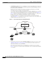
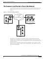
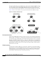
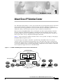
Figure 1-1 shows all the major elements and devices that a service provider can employ to fully deploy
ISC MPLS VPN management services.
A customer edge router (CE) is connected to a provider edge router (PE) in such a way that the
customer’s traffic is encapsulated and transparently sent to other CEs, thus creating a virtual private
network. CEs advertise routes to the VPN for all the devices in their site. The ISC provisioning engine
accesses the configuration files on both the CE and PE to compute the necessary changes to those files
that are required to support the service on the PE-CE link.
Figure 1-1
ISC MPLS VPN Management in the Service Provider Network
Service Provider
network
ISC network management subnet
Processing
server
89996
IP Solution
Center
Management PE
Management VPN
PE
Collection
server
CE 1
CE 2
CE
Multi-VRF
CE
Management CE
PE 1
CE 5
Collection
server
Service provider
MPLS core
CE 4
PE 2
CE 3
Catalyst
2950 switch
Catalyst 3550
Ethernet switch
Cisco IP Solution Center, 3.0: MPLS VPN Management User Guide, 3.0
OL-4344-01
1-1
Chapter 1
About Cisco IP Solution Center
Overview of ISC
The notable ISC network elements are as follows:
•
ISC Network Management Subnet
The ISC Network Management Subnet is required when the service provider’s service offering
entails the management of CEs. The management subnet consists of the ISC workstation (where ISC
is installed). On the same LAN, the service provider can optionally install one or more Processing
servers. The Processing servers are responsible for executing tasks such as provisioning, auditing,
SLA data collection, and so on.
•
The Management VPN
The Management VPN is a special VPN employed by the ISC Network Management Subnet to
manage the CEs in a service provider network. Once a CE is in a VPN, it is no longer accessible by
means of conventional IPv4 routing, unless the CEs are part of the Management VPN. To
communicate with the PEs, the link between the Management PE (MPE) and the Management-CE
(MCE) uses a parallel IPv4 link. The Management VPN connects to the managed CEs.
•
Multi-VRF CE
The Multi-VRF CE is a feature that provides for Layer 3 aggregation. Multiple CEs can connect to
a single Multi-VRF CE (typically in an enterprise network); then the Multi-VRF CE connects
directly to a PE. Figure 1-1 shows CE 1 and CE2 connected to the Multi-VRF CE, and the
Multi-VRF CE is connected directly to the PE. For details, see the “About Multi-VRF CEs” section
on page 1-10.
•
Layer 2 Access to MPLS VPNs
The service provider can install multiple Layer 2 switches between a PE and CE, as shown in
Figure 1-1. This feature provides Layer 2 aggregation. Additional CEs can be connected to the
switches as well. Cisco supports two switches for the Layer 2 access to MPLS: either a Cisco
Catalyst 2950 Switch or a Cisco Catalyst 3550 Intelligent Ethernet Switch.
•
Collection Servers
Cisco ISC is designed to provision a large number of devices through its distributed architecture. If
the Master server (equivalent to the ISC workstation) cannot keep up with the number of devices,
Collection servers can be added to offload the work of the Master server. Among other tasks,
Collection servers are responsible for uploading and downloading configuration files to and from
Cisco routers. For more information, see the “Defining Collection Zones and Assigning Devices to
Zones” section on page 2-13.
Overview of ISC
Cisco ISC offers service providers the ability to plan, provision, operate and bill for the MPLS services.
Using the ISC, service providers can do the following:
•
Provision IP-based MPLS VPN services.
•
Generate audit reports for service requests.
•
Perform data collection to measure SLA performance.
•
Evaluate service usage for each VPN.
An MPLS VPN consists of a set of sites that are interconnected by means of an MPLS provider core
network. At each site, there are one or more CEs, which attach to one or more PEs. PEs use the Border
Gateway Protocol-Multiprotocol (MP-BGP) to dynamically communicate with each other.
Cisco IP Solution Center, 3.0: MPLS VPN Management User Guide, 3.0
1-2
OL-4344-01
Chapter 1
About Cisco IP Solution Center
Overview of ISC
It is not required that the set of IPv4 addresses used in any two VPNs be mutually exclusive because the
PEs translate IPv4 addresses into IPv4 VPN entities by using MP-BGP with extended community
attributes.
The set of IP addresses used in a VPN, however, must be exclusive of the set of addresses used in the
provider network. Every CE must be able to address the PEs to which it is directly attached. Thus, the
IP addresses of the PEs must not be duplicated in any VPN.
ISC Features
ISC offers the following features:
•
High Availability and Distributed Architecture
•
Various protocols supported for the PE-CE link
•
Multicast VPN support
•
VRF Lite/Multi-VRF support
•
Site of Origin support
•
ATM/IMA interface support
•
Unmanaged CPE with no CPE definition required
•
Single service request for multiple MPLS VPN links
•
MPLS VPN Service Policy support
•
Service workflow for customizing MPLS VPN service activation
•
Layer 2 Ethernet Access into MPLS VPNs
One of ISC key features is to hide much of the complexity in dealing with the deployment of Metro
services.
•
Autodiscovery: ISC supports Autodiscovery of network elements, of network topology, and MPLS
VPN services. This feature greatly reduces the initial effort needed to insert ISC in the service
provider’s operation. For details, refer to Chapter 3, “Discovering the Network.”
•
Managed CLE: ISC offers the capability of managing the Customer Located Equipment (CLE),
which gives the service provider the possibility of offering a managed Metro Service to their
customer (configuration, monitoring, and auditing of the managed CLE).
•
Plug and Play: As the network and customer base grow, network elements can be added to the
network. ISC, working in collaboration with CNS Intelligent Agents, is able to detect newly added
Network Elements.
This gives the service provider the ability to rapidly deploy services and network elements.
•
End-To-End Service Management: ISC manages the entire end-to-end provisioning of MPLS
VPN services. Assuming that the network operator defined MPLS VPN service policy and the
parameters that are to be editable by the service operator during the provisioning process, ISC
translates these service requirements into IOS configurations. ISC does a just-in-time Cisco IOS
configuration download, which consist of always validating the configuration of the real devices
before applying the needed configuration.
Once a service is configured, ISC makes sure that the service configuration is the intended one by
checking the configuration and verifying that VPN routing is operational.
Cisco IP Solution Center, 3.0: MPLS VPN Management User Guide, 3.0
OL-4344-01
1-3
Chapter 1
About Cisco IP Solution Center
Overview of ISC
•
VLAN ID Management: ISC allocates VLAN IDs per customer and per Ethernet Service deployed.
The service provider can track per Access Domain a particular allocated VLAN ID (per service or
per customer or per Access Domain).
ISC keeps track of the VLANs allocated and gives detailed usage information of the VLAN
allocated per service, per customer, or per Access Domain.
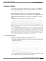
Access Domain: The Layer 2 Ethernet switching domain attached to a PE defines an access domain.
All the switches attached to the PE-POP belong to the access domain (as illustrated in Figure 1-3 on
page 1-5). This notion enables the network operator to tie multiple VLAN pools to a single Access
Domain, and also allows redundancy with dual PEs in a single Access Domain.
For illustration purpose, let’s assume that a Service Provider has a network such as the one
illustrated in Figure 1-2. A customer has two sites (Chicago and New York), and would like to get
an Ethernet Wire Service between the two sites.
Figure 1-2
Service Provider Network for VLAN ID Management
Service Provider
network
89997
IP Solution Center
Network Management
subnet
Management PE
Management VPN
PE
CLE-1
CLE-2
Management CE
Service provider
MPLS core
PE
PE-POP 1
PE
PE-POP 2
CE 2
New York
CE 2
Chicago
1.
If the network operator has chosen the Auto-Pick VLAN ID option in the service policy (see the
“PE Interface Information” section on page 4-11), the network operator must assign an access
domain and a VLAN pool for a given PE-POP.
This automatically gives ISC the range of VLAN IDs that are attached to the access domain.
Figure 1-3 shows the access domain assigned, with PE-POP 1, CLE 1, and CLE 2 defined within the
access domain.
Cisco IP Solution Center, 3.0: MPLS VPN Management User Guide, 3.0
1-4
OL-4344-01
Chapter 1
About Cisco IP Solution Center
Overview of ISC
Figure 1-3
Access Domain Assigned
Service Provider
network
89998
IP Solution Center
Network Management
subnet
Management PE
Management VPN
PE
Access domain
CLE-1
CLE-2
Management CE
Service provider
MPLS core
PE
PE-POP 1
PE
PE-POP 2
CE 2
New York
CE 2
Chicago
2.
All the network elements have been discovered during the Autodiscovery process, as well as the
network topology (connectivity between sites).
3.
The service operator wants to deploy an Ethernet over MPLS service from Chicago to New York.
4.
Using ISC’s GUI, the service operator needs to select the From and To ports, and the appropriate
service policy that allows VLAN IDs in the Access Domain to be picked automatically.
5.
ISC allocated a VLAN ID for Chicago and a VLAN ID for New York. (Both sites belong to the same
customer.)
6.
VLAN IDs are allocated and assigned.
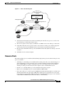
Resource Pools
ISC enables multiple pools to be defined and used during deployment operations. The following resource
pools are available:
•
VLAN ID pool: VLAN ID pools are defined with a starting value and a size of the VLAN pool. A
given VLAN ID pool can be attached to an Access Domain. During the deployment an Ethernet
Service (EWS, ERS for example), VLAN ID can be auto-allocated from the Access Domain’s
VLAN pools. This gives the Service Provider a tighter control of VLAN ID allocation.
•
IP address pool: The IP address pool can be defined and assigned to regions.
•
Multicast pool: The Multicast pool is used for Multicast MPLS VPNs.
•
Route Target (RT) pool: A route target is the MPLS mechanism that informs PEs as to which routes
should be inserted into the appropriate VRFs. Every VPN route is tagged with one or more route
targets when it is exported from a VRF and offered to other VRFs. The route target can be considered
a VPN identifier in MPLS VPN architecture. RTs are a 64-bit number.
Cisco IP Solution Center, 3.0: MPLS VPN Management User Guide, 3.0
OL-4344-01
1-5
Chapter 1
About Cisco IP Solution Center
Overview of ISC
•
Route Distinguisher (RD) pool: The IP subnets advertised by the CE routers to the PE routers are
augmented with a 64-bit prefix called a route distinguisher (RD) to make them unique. The resulting
96-bit addresses are then exchanged between the PEs, using a special address family of
Multiprotocol BGP (referred to as MP-BGP). The RD pool is a pool of 64-bit RD values that ISC
uses to make sure the IP addresses in the network are unique.
•
Site of origin pool: The pool of values for the site-of-origin attribute. The site-of-origin attribute
prevents routing loops when a site is multihomed to the MPLS VPN backbone. This is achieved by
identifying the site from which the route was learned, based on its SOO value, so that it is not
readvertised back to that site from a PE in the MPLS VPN network.
All these resources, that are made available to the service provider, enable the automation of service
deployment.
Features and Functions Provided in Provisioning with ISC
ISC assumes that the iBGPv4 core over MPLS, IGP, and VPNv4 neighbors are preprovisioned.
The features and functions provided in provisioning MPLS VPNs are as follows:
•
ISC configures the IP addresses on the CE and PE interfaces.
IP addresses are assumed to be specified by the service provider and unique in the network.
•
Configures CE and PE routing.
This allocates the PE VRF, route target, and route distinguisher values
•
Advertises CE site routes to other sites in the same VPN.
•
Supports unmanaged CEs
•
Allows service request removal and modification
•
Support for MP-BGPv4 commands
– BGP transparent: PE to CE routing protocol metric preserved between VPN sites.
– Neighbor AS override: You can reuse the same autonomous system number between VPN sites.
– AS-allow: Allows an autonomous system number multiple times in the AS path.
•
Supports VRF commands:
– import map
– export map
– maximum routes in a VRF
•
Management VPN support
•
Provisioning of CE Loopback interfaces
VPN Service Profile-Based Provisioning
For all MPLS VPN provisioning, several network elements that participate in the VPN must be defined.
These parameters are:
•
Choice of protocols between PE-CE and their intrinsic characteristics.
•
IP addressing for each site joining the IP VPN
Cisco IP Solution Center, 3.0: MPLS VPN Management User Guide, 3.0
1-6
OL-4344-01
Chapter 1
About Cisco IP Solution Center
Overview of ISC
•
VRF configuration (export map, import map, maximum number of routes, VRF and RD override,
and so forth)
•
Choice of joining the VPN as hub or spoke
•
Choice of interfaces on the PE, CE, and intermediate network devices
All the provisioning parameters can be made editable for a service operator who will deploy the service.
A service policy is defined by a network operator and used by a service operator.
A service policy defines the parameters that will be used during provisioning.
Each of these parameters can be made editable or not to the inexperienced service operator. The fact that
a service can be profiled greatly simplifies the service operator’s tasks and has now only limited number
of parameters to enter during the provisioning process to deploy and activate a MPLS VPN service.
Role-Based Access Control (RBAC)
The central notion of role-based access control (RBAC) is that permissions are associated with roles, and
users are made members of appropriate roles. Access control policy is embodied in various components
of RBAC, such as role-permission, user-role, and role-role relationships. These components determine
whether a particular user will be allowed to access a particular piece of data in the system.
The Role object specifies a set of occupants and the privileges or permissions granted to those occupants.
There are several ways for constructing a role.
A role can represent competency to do specific tasks, such as a technician or a support engineer. A
technician can collect edge device and interface information and import them into the ISC Repository.
A support engineer (service operator) can create policies, submit service requests and deploy them.
A role can reflect specific duty assignments, for example, an engineer can be assigned to provision
customer Acme’s VPN. The operator may not be allowed to provision the competitor customer Widget’s
VPN.
A role can have distinct authority, for example, VPN customer AcmeInc should be allowed only to view
or make minor change on Acme’s VPN data. The customer should not be allowed to access any other
customer’s VPN data.
There can be a role hierarchy in which a super user has all the permissions allowed to two different roles.
The service provider can define a role for each VPN customer, for example Acme and Widgets. The
acme_customers role and the Widgets_customers role are mutually exclusive roles. The same user can
be assigned to no more than one role in a mutually exclusive set. Role constraint supports separation of
duties.
ISC supports full Role-Based Access Control to the system resources. Each Role defines limited access
to the resources with a set of permissions: view, create, update, delete, and execute. This same access
mechanism is also given to a group. When a user is part of a group, he inherits the group’s access
privileges.
Each user can be assigned one or many roles. Each user will be shown only the resources and services
that he or she is allowed to create view, modify, or delete. Using the access privileges that the user has
been allocated, the display and action allowed are adjusted accordingly.
Cisco IP Solution Center, 3.0: MPLS VPN Management User Guide, 3.0
OL-4344-01
1-7
Chapter 1
About Cisco IP Solution Center
Overview of ISC
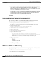
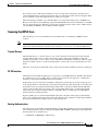
Figure 1-4
Defining the User Role
ISC Service Request States
WAIT
DEPLOY
FAILED
DEPLOY
Provisioning States
FAILED
AUDIT
Auditing States
PENDING
DEPLOYED
FUNCTIONAL
INVALID
CLOSED
LOST
BROKEN
93827
REQUESTED
The permissions to Create, View, Modify, and Delete are enforced for the following resources:
•
Persistent task
•
MPLS policy
•
SAA probe
•
MPLS service request
•
Workflow
•
Layer 2 VPN policy
•
Device
•
Layer 2 VPN service request
•
ISC host
•
Firewall policy
•
Customer
•
Firewall service request
•
Provider
•
Network Address Translation service request
•
PE
•
IPsec policy
•
CPE
•
IPsec service request
•
Qos Policy
•
Deployment flow
•
Qos service request
•
Template
Cisco IP Solution Center, 3.0: MPLS VPN Management User Guide, 3.0
1-8
OL-4344-01
Chapter 1
About Cisco IP Solution Center
The Customer’s and Provider’s View of the Network
The Customer’s and Provider’s View of the Network
From the customer’s point of view, they see their internal routers communicating with their customer
edge routers (CEs) from one site to another through a VPN managed by the service provider (see
Figure 1-5).
Figure 1-5
The Customer’s View of the Network
Service provider
network
CE
CE
Gadgets, Inc's VPN
Gadgets, Inc.
New York City
Gadgets, Inc.
Seattle
28554
CE
Gadgets, Inc.
Chicago
This simple view of the customer’s network is the advantage of employing VPNs: the customer
experiences direct communication to their sites as though they had their own private network, even
though their traffic is traversing a public network infrastructure and they are sharing that infrastructure
with other businesses.
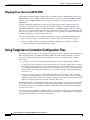
The service provider’s view of the network is naturally very different, as shown in Figure 1-6. This
illustration shows two different customers, with each customer having a single VPN. A customer can,
however, have multiple VPNs.
Cisco IP Solution Center, 3.0: MPLS VPN Management User Guide, 3.0
OL-4344-01
1-9
Chapter 1
About Cisco IP Solution Center
The Customer’s and Provider’s View of the Network
Figure 1-6
Service Provider’s View of the Network
VPN 10
CE
Gadgets, Inc.
Seattle
VPN 10
Service provider network
BGP
PE-1
BGP
CE
Gadgets, Inc.
New York City
PE-2
MPLS core
BGP
VPN 15
VPN 15
PE-3
VPN 10
VPN 15
CE
Gizmos, Intl.
San Francisco
CE
Gadgets, Inc.
Chicago
CE
Gizmos, Intl.
Berlin
28555
CE
Gizmos, Intl.
London
About Provider Edge Routers (PEs)
At the edge of the provider network are provider edge routers (PEs). Within the provider network are
other provider routers as needed (often designated as P routers) that communicate with each other and
the PEs via the Border Gateway Protocol-Multiprotocol (MP-BGP). Note that in this model, the service
provider need only provision the links between the PEs and CEs.
PEs maintain separate routing tables called VPN routing and forwarding tables (VRFs). The VRFs
contain the routes for directly connected VPN sites only. (For more information about VRFs, see the
“VPN Routing and Forwarding Tables (VRFs)” section on page 1-16). PEs exchange VPN-IPv4 updates
through MP-iBGP sessions. These updates contain VPN-IPv4 addresses and labels. The PE originating
the route is the next hop of the route. PE addresses are referred to as host routes into the core interior
gateway protocol.
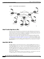
About Multi-VRF CEs
The Multi-VRF CE is a feature that provides for Layer 3 aggregation. Multiple CEs can connect to a
single Multi-VRF CE (typically in an enterprise network); then the Multi-VRF CE connects directly to
a PE. A Multi-VRF CE can be a Cisco router or a Cisco Catalyst® 3550 Intelligent Ethernet Switch.
The Multi-VRF CE functionality extends some of the functionality formerly reserved to the PE to a CE
router in an MPLS VPN—the only PE-like functionality that this feature provides is the ability to have
multiple VRFs on the CE router so that different routing decisions can be made. The packets are sent
toward the PE as IP packets.
With this feature, a Multi-VRF CE can maintain separate VRF tables to extend the privacy and security
of an MPLS VPN down to a branch office, rather than just at the PE router node.
Cisco IP Solution Center, 3.0: MPLS VPN Management User Guide, 3.0
1-10
OL-4344-01
Chapter 1
About Cisco IP Solution Center
The Customer’s and Provider’s View of the Network
A Multi-VRF CE is unlike a CE in that there is no label exchange, no LDP adjacency, and no labeled
packet flow between the PE and the CE. Multi-VRF CE routers use VRF interfaces to form a VLAN-like
configuration on the customer side. Each VRF on the Multi-VRF CE router is mapped to a VRF on the
PE router.
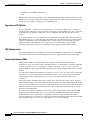
Figure 1-7 illustrates one method in which a Multi-VRF CE can be used. The Multi-VRF CE router
associates a specific VRF by the CEs connected to its interfaces and exchanges that information with the
PE. Routes are installed in the VRF on the Multi-VRF CE. There also needs to be a routing protocol or
a static route that propagates routes from a specific VRF on the Multi-VRF CE to the corresponding VRF
on the PE.
Figure 1-7
A Multi-VRF CE Providing Layer 3 Aggregation
CE 1
10.1/16
Multi-VRF
CE
Service
Provider
Network
T1 line
PE 1
MPLS
Core
Network
CE 2
CE 3
10.1/24
VRF Red
VRF Red
93165
11.1/16
The Multi-VRF CE feature can segment its LAN traffic by placing each CE with its own IP address
space. To differentiate each CE, each interface contains its own IP address space.
When receiving an outbound customer data packet from a directly attached interface, the Multi-VRF CE
router performs a route lookup in the VRF that is associated with that site. The specific VRF is
determined by the interface or subinterface over which the data packet is received. Support for multiple
forwarding tables makes it easy for the Multi-VRF CE router to provide segregation of routing
information on a per-VPN basis before the routing information is sent to the PE. The use of a T1 line
with multiple point-to-point subinterfaces allows traffic from the Multi-VRF CE router to the PE router
to be segmented into each corresponding VRF.
With a Multi-VRF CE, the data path is as follows from the CEs to PE 1 (as shown in Figure 1-7):
1.
The Multi-VRF CE learns the VPN Red routes to CE 1 from an interface directly attached to the
Multi-VRF CE.
2.
The Multi-VRF CE then installs these routes into the VRF on the Multi-VRF CE (VRF Red).
3.
PE 1 learns the VPN Red routes to CE 1 from the same VRF Red and installs the routes into
VRF Red on PE-1.
Cisco IP Solution Center, 3.0: MPLS VPN Management User Guide, 3.0
OL-4344-01
1-11
Chapter 1
About Cisco IP Solution Center
Using Templates to Customize Configuration Files
Mapping IPsec Tunnels to MPLS VPNs
Provisioning network-based IPsec VPNs in order to map IPsec tunnels to MPLS VPNs involves both
MPLS and IPsec services in IP Solutions Center. Thus, it is necessary to create both MPLS and IPsec
policies, as well as MPLS and IPsec service requests. For details, see Chapter 6, “Mapping IPsec to
MPLS VPN.”
The IPsec terminating router resides on the service provider premises. IPsec tunnels from various
customers are aggregated on this router. This may be either a PE router or a Multi-VRF CE router.
Depending on which type of device is employed, the IPsec- to-MPLS mapping is either the “one-box”
solution or a “two-box” solution. In the “one-box” solution, the service provider uses a PE router as the
IPsec aggregator, whereas in the “two-box” solution, the service provider uses a Multi-VRF CE router
for IPsec aggregation in conjunction with a PE router.
Two types of IPsec tunnels can be terminated on the IPsec aggregator (PE or Multi-VRF CE router):
•
Site-to-site IPsec tunnels: A tunnel between a customer’s CE router and the IPsec aggregator.
•
Remote access IPsec tunnels: A tunnel initiated from a VPN client, for example, a Windows
workstation running Cisco IPsec VPN Client software.
Using Templates to Customize Configuration Files
The Template Manager in ISC is a provisioning system that provides fast, flexible, and extensible Cisco
IOS command generation capability. The Template Manager defines standard templates to generate
Cisco IOS configurations for common provisioning tasks, such as common IPv4, QoS, and VPN
provisioning.
•
A template file is a file created by the Template Manager that stores a ISC template definition.
•
A template data file is a text file that stores variable values to generate the template file. A valid data
file contains name-value pairs for all the variables defined in a template. Each template file can be
associated with multiple data files; however, note that each data file can only be associated with a
single template. You can select which data file to use to generate a template. The filename suffix for
data files is .dat.
•
A template configuration file is an IOS configuration file that stores the Cisco IOS commands
created by the Template Manager. A template configuration file can be either a partial or complete
configuration file. When you generate a template configuration file using a particular data file, the
template configuration filename is the same as the data file’s name.
The template data files are tightly linked with its corresponding template. You can use a data file and its
associated template to create a template configuration file. The template configuration file is merged
with (either appended to or prepended to) the ISC configlet. ISC downloads the combined configlet to
the edge device router.
You can apply the same template to multiple edge devices, assigning the appropriate template data file
for each device. Each template data file includes the specific data for a particular device (for example,
the management IP address or host name of each device).
Cisco IP Solution Center, 3.0: MPLS VPN Management User Guide, 3.0
1-12
OL-4344-01
Chapter 1
About Cisco IP Solution Center
Using Templates to Customize Configuration Files
The template files and data files are in XML format. The template file, its data files, and all template
configuration file files are mapped to a single directory.
•
ISC creates the initial ISC configlet. Through the Template Manager, you can create a template
configuration file. You can then associate a template configuration file with a service request, which
effectively merges the ISC configlet and the template configuration file. You can then download this
merged ISC configlet to the target router (or routers).
•
You can also create a template configuration file and download it directly to a router.
Uses for the Template Function
Service providers can use the Template Manager to enhance ISC functionality. You can use the Template
Manager to provide initial configuration for any service provider core device or edge device.
The Template Manager can be used as a stand-alone tool to generate complete configuration files that
you can download to any ISC target.
Some of the additional uses for templates are as follows:
•
IOS firewall provisioning
•
Add a set of commands that ISC does not include to a service request; for example, provisioning
ATM Class of Service.
•
Use the template feature to apply Class of Service using IP connectivity.
•
Download a ISC service request and an Cisco IOS configuration file in one download operation
through the console. This edge device staging method would create a template and apply the service
request in one step.
Auditing Service Requests
A service request audit verifies that service requests are deployed on the network. You can audit new or
existing requests. A service request audit can be scheduled on a regular basis to verify the state of the
network provisioning requests. The audit verifies the following:
•
Verifies the IOS configuration on all network devices.
•
Verifies the routing tables and routing for the VPN.
ISC audits against the Repository, not the network. The service operator should schedule auditing after
the collection of configuration and routing tables has taken place.
Auditing an existing service request involves three tasks:
•
Collects configuration
•
Collects routing
•
Runs an audit against the specified service requests
Auditing Report Services
Audit reports provide these services:
•
Audit New Services: Handles auditing of services requested but not yet deployed (that is, the
configuration is not apparent in the router).
The Audit New Services also identifies problems with the download of configuration files to routers
Cisco IP Solution Center, 3.0: MPLS VPN Management User Guide, 3.0
OL-4344-01
1-13
Chapter 1
About Cisco IP Solution Center
About MPLS VPNs
•
Audit Existing Services: Checks and evaluates configuration of deployed service to see if the service
is still in effect.
•
Audit Routing Reports: Checks the VRF for the VPN on the PE. This report also checks if VPN
connectivity is operational by evaluating reachability of the network devices in the VPN.
About MPLS VPNs
At its simplest, a virtual private network (VPN) is a collection of sites that share the same routing table.
A VPN is also a network in which customer connectivity to multiple sites is deployed on a shared
infrastructure with the same administrative policies as a private network.The path between two systems
in a VPN, and the characteristics of that path, may also be determined (wholly or partially) by policy.
Whether a system in a particular VPN is allowed to communicate with systems not in the same VPN is
also a matter of policy.
In MPLS VPN, a VPN generally consists of a set of sites that are interconnected by means of an MPLS
provider core network, but it is also possible to apply different policies to different systems that are
located at the same site. Policies can also be applied to systems that dial in; the chosen policies would
be based on the dial-in authentication processes.
A given set of systems can be in one or more VPNs. A VPN can consist of sites (or systems) that are all
from the same enterprise (intranet), or from different enterprises (extranet); it may consist of sites (or
systems) that all attach to the same service provider backbone, or to different service provider
backbones.
VPNs Sharing Sites
Site 1
VPN A
Site 4
Site 2
Site 3
VPN B
VPN C
28563
Figure 1-8
MPLS-based VPNs are created in Layer 3 and are based on the peer model, which makes them more
scalable and easier to build and manage than conventional VPNs. In addition, value-added services, such
as application and data hosting, network commerce, and telephony services, can easily be targeted and
deployed to a particular MPLS VPN because the service provider backbone recognizes each MPLS VPN
as a secure, connectionless IP network.
The MPLS VPN model is a true peer VPN model that enforces traffic separations by assigning unique
VPN route forwarding tables (VRFs) to each customer’s VPN. Thus, users in a specific VPN cannot see
traffic outside their VPN. Traffic separation occurs without tunneling or encryption because it is built
directly into the network. (For more information on VRFs, see the “VPN Routing and Forwarding Tables
(VRFs)” section on page 1-16.)
The service provider’s backbone is comprised of the PE and its provider routers. MPLS VPN provides
the ability that the routing information about a particular VPN be present only in those PE routers that
attach to that VPN.
Cisco IP Solution Center, 3.0: MPLS VPN Management User Guide, 3.0
1-14
OL-4344-01
Chapter 1
About Cisco IP Solution Center
About MPLS VPNs
Characteristics of MPLS VPNs
MPLS VPNs have the following characteristics:
•
Multiprotocol Border Gateway Protocol-Multiprotocol (MP-BGP) extensions are used to encode
customer IPv4 address prefixes into unique VPN-IPv4 Network Layer Reachability Information
(NLRI) values.
NLRI refers to a destination address in MP-BGP, so NLRI is considered “one routing unit.” In the
context of IPv4 MP-BGP, NLRI refers to a network prefix/prefix length pair that is carried in the
BGP4 routing updates.
•
Extended MP-BGP community attributes are used to control the distribution of customer routes.
•
Each customer route is associated with an MPLS label, which is assigned by the provider edge router
that originates the route. The label is then employed to direct data packets to the correct egress
customer edge router.
When a data packet is forwarded across the provider backbone, two labels are used. The first label
directs the packet to the appropriate egress PE; the second label indicates how that egress PE should
forward the packet.
•
Cisco MPLS CoS and QoS mechanisms provide service differentiation among customer data
packets.
•
The link between the PE and CE routers uses standard IP forwarding.
The PE associates each CE with a per-site forwarding table that contains only the set of routes
available to that CE.
Principal Technologies
There are four principal technologies that make it possible to build MPLS-based VPNs:
•
Multiprotocol Border Gateway Protocol (MP-BGP) between PEs carries CE routing information
•
Route filtering based on the VPN route target extended MP-BGP community attribute
•
MPLS forwarding carries packets between PEs (across the service provider backbone)
•
Each PE has multiple VPN routing and forwarding instances (VRFs)
Intranets and Extranets
If all the sites in a VPN are owned by the same enterprise, the VPN is a corporate intranet. If the various
sites in a VPN are owned by different enterprises, the VPN is an extranet. A site can be in more than one
VPN. Both intranets and extranets are regarded as VPNs.
While the basic unit of interconnection is the site, the MPLS VPN architecture allows a finer degree of
granularity in the control of interconnectivity. For example, at a given site, it may be desirable to allow
only certain specified systems to connect to certain other sites. That is, certain systems at a site may be
members of an intranet as well as members of one or more extranets, while other systems at the same
site may be restricted to being members of the intranet only.
A CE router can be in multiple VPNs, although it can only be in a single site. When a CE router is in
multiple VPNs, one of these VPNs is considered its primary VPN. In general, a CE router’s primary VPN
is the intranet that includes the CE router’s site. A PE router may attach to CE routers in any number of
different sites, whether those CE routers are in the same or in different VPNs. A CE router may, for
robustness, attach to multiple PE routers. A PE router attaches to a particular VPN if it is a router
adjacent to a CE router that is in that VPN.
Cisco IP Solution Center, 3.0: MPLS VPN Management User Guide, 3.0
OL-4344-01
1-15
Chapter 1
About Cisco IP Solution Center
About MPLS VPNs
VPN Routing and Forwarding Tables (VRFs)
The VPN routing and forwarding table (VRF) is a key element in the MPLS VPN technology. VRFs exist
on PEs only (except in the case of a Multi-VRF CE). A VRF is a routing table instance, and more than
one VRF can exist on a PE. A VPN can contain one or more VRFs on a PE. The VRF contains routes
that should be available to a particular set of sites. VRFs use Cisco Express Forwarding (CEF)
technology, therefore the VPN must be CEF-enabled.
A VRF is associated with the following elements:
•
IP routing table
•
Derived forwarding table, based on the Cisco Express Forwarding (CEF) technology
•
A set of interfaces that use the derived forwarding table
•
A set of routing protocols and routing peers that inject information into the VRF
Each PE maintains one or more VRFs. ISC software looks up a particular packet’s IP destination address
in the appropriate VRF only if that packet arrived directly through an interface that is associated with
that VRF. The so-called “color” MPLS label tells the destination PE to check the VRF for the appropriate
VPN so that it can deliver the packet to the correct CE and finally to the local host machine.
A VRF is named based on the VPN or VPNs it services, and on the role of the CE in the topology. The
schemes for the VRF names are as follows:
The VRF name for a hub: ip vrf Vx:[VPN_name]
The x parameter is a number assigned to make the VRF name unique.
For example, if we consider a VPN called Blue, then a VRF for a hub CE would be called:
ip vrf V1:blue
A VRF for a spoke CE in the Blue VPN would be called:
ip vrf V1:blue-s
A VRF for an extranet VPN topology in the Green VPN would be called:
ip vrf V1:green-etc
Thus, you can read the VPN name and the topology type directly from the name of the VRF.
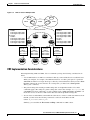
Figure 1-9 shows a network in which two of the four sites are members of two VPNs, and illustrates
which routes are included in the VRFs for each site.
Cisco IP Solution Center, 3.0: MPLS VPN Management User Guide, 3.0
1-16
OL-4344-01
Chapter 1
About Cisco IP Solution Center
About MPLS VPNs
VRFs for Sites in Multiple VPNs
Site 1
VPN A
ip vrf site1
rd 100:1
route-target export 100:1
route-target import 100:1
ip vrf site2
rd 100:2
route-target export 100:2
route-target import 100:2
route-target import 100:1
route-target export 100:1
VRF
for site 1
(100:1)
Site 1 routes
Site 2 routes
Site 1
Site 4
VPN B
Site 2
Site 3
VPN C
Multihop MP-iBGP
P
P
PE1
PE2
VRF
for site 2
(100:2)
Site 1 routes
Site 2 routes
Site 3 routes
VRF
for site 3
(100:3)
Site 2 routes
Site 3 routes
Site 4 routes
Site 2
Site 3
ip vrf site3
rd 100:3
route-target export 100:2
route-target import 100:2
route-target import 100:3
route-target export 100:3
ip vrf site4
rd 100:4
route-target export 100:3
route-target import 100:3
VRF
for site 4
(100:4)
Site 3 routes
Site 4 routes
28558
Figure 1-9
Site 4
VRF Implementation Considerations
When implementing VPNs and VRFs, Cisco recommends you keep the following considerations in
mind:
•
A local VRF interface on a PE is not considered a directly-connected interface in a traditional sense.
When you configure, for example, a Fast Ethernet interface on a PE to participate in a particular
VRF/VPN, the interface no longer shows up as a directly-connected interface when you issue a show
ip route command. To see that interface in a routing table, you must issue a show ip route
vrf vrf_name command.
•
The global routing table and the per-VRF routing table are independent entities. Cisco IOS
commands apply to IP routing in a global routing table context. For example, show ip route, and
other EXEC-level show commands—as well as utilities such as ping, traceroute, and telnet—all
invoke the services of the Cisco IOS routines that deal with the global IP routing table.
•
You can issue a standard Telnet command from a CE router to connect to a PE router. However, from
that PE, you must issue the following command to connect from the PE to the CE:
telnet CE_RouterName /vrf vrf_name
Similarly, you can utilize the Traceroute and Ping commands in a VRF context.
Cisco IP Solution Center, 3.0: MPLS VPN Management User Guide, 3.0
OL-4344-01
1-17
Chapter 1
About Cisco IP Solution Center
About MPLS VPNs
•
The MPLS VPN backbone relies on the appropriate Interior Gateway Protocol (IGP) that is
configured for MPLS, for example, EIGRP, or OSPF. When you issue a show ip route command on
a PE, you see the IGP-derived routes connecting the PEs together. Contrast that with the show ip
route vrf VRF_name command, which displays routes connecting customer sites in a particular
VPN.
Creating a VRF Instance
The configuration commands to create a VRF instance are as follows:
Step 1
Command
Description
Router# configure terminal
Enter global configuration mode.
Router(config)#
Step 2
Router(config)# ip vrf vrf_name
For example, ip vrf CustomerA initiates a VPN routing table
and an associated CEF table named CustomerA. The command
enters VRF configuration submode to configure the variables
associated with the VRF.
Step 3
Router(config-vrf)# rd RD_value
Enter the eight-byte route descriptor (RD) or IP address. The PE
prepends the RD to the IPv4 routes prior to redistributing the
route into the MPLS VPN backbone.
Step 4
Router(config-vrf)# route-target import |
export | both community
Enter the route-target information for the VRF.
Route Distinguishers and Route Targets
MPLS-based VPNs employ BGP to communicate between PEs to facilitate customer routes. This is
made possible through extensions to BGP that carry addresses other than IPv4 addresses. A notable
extension is called the route distinguisher (RD).
The purpose of the route distinguisher (RD) is to make the prefix value unique across the backbone.
Prefixes should use the same RD if they are associated with the same set of route targets (RTs) and
anything else that is used to select routing policy. The community of interest association is based on the
route target (RT) extended community attributes distributed with the Network Layer Reachability
Information (NLRI).The RD value must be a globally unique value to avoid conflict with other prefixes.
The MPLS label is part of a BGP routing update. The routing update also carries the addressing and
reachability information. When the RD is unique across the MPLS VPN network, proper connectivity is
established even if different customers use non-unique IP addresses.
For the RD, every CE that has the same overall role should use a VRF with the same name, same RD,
and same RT values. The RDs and RTs are only for route exchange between the PEs running BGP. That
is, for the PEs to do MPLS VPN work, they have to exchange routing information with more fields than
usual for IPv4 routes; that extra information includes (but is not limited to) the RDs and RTs.
The route distinguisher values are chosen by the ISC software.
•
CEs with hub connectivity use bgp_AS:value.
•
CEs with spoke connectivity use bgp_AS:value + 1
Each spoke uses its own RD value for proper hub and spoke connectivity between CEs; therefore, the
ISC software implements a new RD for each spoke that is provisioned.
Cisco IP Solution Center, 3.0: MPLS VPN Management User Guide, 3.0
1-18
OL-4344-01
Chapter 1
About Cisco IP Solution Center
About MPLS VPNs
ISC chooses route target values by default, but you can override the automatically assigned RT values if
necessary when you first define a CERC in the ISC software (see the “Defining CE Routing
Communities” section on page 4-5).
Route Target Communities
The mechanism by which MPLS VPN controls distribution of VPN routing information is through the
VPN route-target extended MP-BGP communities. An extended MP-BGP community is an eight octet
structure value. MPLS VPN uses route-target communities as follows:
•
When a VPN route is injected into MP-BGP, the route is associated with a list of VPN route-target
communities. Typically, this is set through an export list of community values associated with the
VRF from which the route was learned.
•
An import list of route-target communities is associated with each VRF. This list defines the values
that should be matched against to decide whether a route is eligible to be imported into this VRF.
For example, if the import list for a particular VRF is {A, B, C}, then any VPN route that carries
community value A, B, or C is imported into the VRF.
CE Routing Communities
A VPN can be organized into subsets called CE routing communities, or CERCs. A CERC describes how
the CEs in a VPN communicate with each other. Thus, CERCs describe the logical topology of the VPN.
ISC can be employed to form a variety of VPN topologies between CEs by building hub and spoke or
full mesh CE routing communities. CERCs are building blocks that allow you to form complex VPN
topologies and CE connectivity.
The most common types of VPNs are hub-and-spoke and full mesh.
•
A hub-and-spoke CERC is one in which one or a few CEs act as hubs, and all spoke CEs talk only
to or through the hubs, never directly to each other.
•
A full mesh CERC is one in which every CE connects to every other CE.
These two basic types of VPNs—full mesh and hub and spoke—can be represented with a single CERC.
Whenever you create a VPN, the ISC software creates one default CERC for you. This means that until
you need advanced customer layout methods, you will not need to define new CERCs. Up to that point,
you can think of a CERC as standing for the VPN itself—they are one and the same. If, for any reason,
you need to override the software’s choice of route target values, you can do so only at the time you
create a CERC in the ISC software (see the “Defining CE Routing Communities” section on page 4-5).
To build very complex topologies, it is necessary to break down the required connectivity between CEs
into groups, where each group is either fully meshed, or has a hub and spoke pattern. (Note that a CE
can be in more than one group at a time, so long as each group has one of the two basic patterns.) Each
subgroup in the VPN needs its own CERC. Any CE that is only in one group just joins the corresponding
CERC (as a spoke if necessary). If a CE is in more than one group, then you can use the Advanced Setup
choice during provisioning to add the CE to all the relevant groups in one service request. Given this
information, the provisioning software does the rest, assigning route target values and VRF tables to
arrange exactly the connectivity the customer requires. You can use the Topology tool to double-check
the CERC memberships and resultant VPN connectedness.
Cisco IP Solution Center, 3.0: MPLS VPN Management User Guide, 3.0
OL-4344-01
1-19
Chapter 1
About Cisco IP Solution Center
About MPLS VPNs
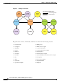
ISC supports multiple CEs per site and multiple sites connected to the same PE. Each CERC has unique
route targets (RT), route distinguisher (RD) and VRF naming. After provisioning a CERC, it is a good
idea to run the audit reports to verify the CERC deployment and view the topologies created by the
service requests. The product supports linking two or more CE routing communities in the same VPN.
Figure 1-10 shows several examples of the topologies that IP Solution Center CERCs can employ.
Figure 1-10 Examples of CERC Topologies
Full mesh; CERC 1
CE 1
Hub and spoke; CERC 1
CE 4
CE 3
CE 2
CE 5
Complex CERCs 3 and 4
CE 6
Multi VPN CERCs
CE 3 (spoke)
CE 4
CE 1
CE 3
CE 2
CE 5
CERC 3
CERC 4
CERC 6
CE 1 (hub)
CE 2 (hub)
28902
CERC 5
Hub and Spoke Considerations
In hub-and-spoke MPLS VPN environments, the spoke routers have to have unique Route Distinguishers
(RDs). In order to use the hub site as a transit point for connectivity in such an environment, the spoke
sites export their routes to the hub. Spokes can talk to hubs, but spokes never have routes to other spokes.
Due to the current MPLS VPN implementation, you must apply a different RD for each spoke VRF. The
MP-BGP selection process applies to all the routes that have to be imported into the same VRF plus all
routes that have the same RD of such a VRF. Once the selection process is done, only the best routes are
imported. In this case this can result in a best route which is not imported. Thus, customers must have
different RDs per spoke-VRF.
Full Mesh Considerations
Each CE Routing Community (CERC) has two distinct RTs: a hub RT and a spoke RT. When building a
full mesh topology, always use the hub RT. Thus, when a need arises to add a spoke site for the current
full mesh topology, you can easily add the spoke site without reconfiguring any of the hub sites. The
existing spoke RT can be used for this purpose. This is a strategy to prevent having to do significant
reprovisioning of a full mesh topology to a hub-and-spoke topology.
Cisco IP Solution Center, 3.0: MPLS VPN Management User Guide, 3.0
1-20
OL-4344-01
Chapter 1
About Cisco IP Solution Center
Security Requirements for MPLS VPNs
Security Requirements for MPLS VPNs
This section discusses the security requirements for MPLS VPN architectures. This section concentrates
on protecting the core network against attacks from the “outside,” that is, the Internet and connected
VPNs. Protection against attacks from the “inside,” that is, when an attacker has logical or physical
access to the core network is not discussed here, since any network can be attacked with access from the
inside.
Address Space and Routing Separation
Between two non-intersecting VPNs of an MPLS VPN service, it is assumed that the address space
between different VPNs is entirely independent. This means, for example, that two non-intersecting
VPNs must be able to both use the 10/8 network without any interference. From a routing perspective,
this means that each end system in a VPN has a unique address, and all routes to this address point to
the same end system. Specifically:
•
Any VPN must be able to use the same address space as any other VPN.
•
Any VPN must be able to use the same address space as the MPLS core.
•
Routing between any two VPNs must be independent.
•
Routing between any VPN and the core must be independent.
Address Space Separation
From a security point of view, the basic requirement is to avoid that packets destined to a host a.b.c.d
within a given VPN reach a host with the same address in another VPN or the core.
MPLS allows distinct VPNs to use the same address space, which can also be private address space. This
is achieved by adding a 64-bit route distinguisher (RD) to each IPv4 route, making VPN-unique
addresses also unique in the MPLS core. This “extended” address is also called a VPN-IPv4 address.
Thus customers of an MPLS service do not need to change current addressing in their networks.
In the case of using routing protocols between CE and PE routers (for static routing this is not an issue),
there is one exception—the IP addresses of the PE routers the CE routers are peering with. To be able to
communicate to the PE router, routing protocols on the CE routers must configure the address of the peer
router in the core. This address must be unique from the CE router’s perspective. In an environment
where the service provider manages also the CE routers as CPE (customer premises equipment), this can
be made invisible to the customer.
Routing Separation
Routing separation between the VPNs can also be achieved. Every PE router maintains a separate Virtual
Routing and Forwarding instance (VRF) for each connected VPN. Each VRF on the PE router is
populated with routes from one VPN, through statically configured routes or through routing protocols
that run between the PE and the CE router. Since every VPN results in a separate VRF, there are no
interferences between the VPNs on the PE router.
Across the MPLS core to the other PE routers, this routing separation is maintained by adding unique
VPN identifiers in multi-protocol BGP, such as the route distinguisher (RD). VPN routes are exclusively
exchanged by MP-BGP across the core, and this BGP information is not redistributed to the core
network, but only to the other PE routers, where the information is kept again in VPN-specific VRFs.
Thus routing across an MPLS network is separate per VPN.
Cisco IP Solution Center, 3.0: MPLS VPN Management User Guide, 3.0
OL-4344-01
1-21
Chapter 1
About Cisco IP Solution Center
Security Requirements for MPLS VPNs
Given addressing and routing separation across an MPLS core network, MPLS offers in this respect the
same security as comparable Layer 2 VPNs, such as ATM or Frame Relay. It is not possible to intrude
into other VPNs through the MPLS core, unless this has been configured specifically.
Hiding the MPLS Core Structure
The internal structure of the MPLS core network (PE and Provider router devices) should not be visible
to outside networks (either the Internet or any connected VPN). While a breach of this requirement does
not lead to a security problem itself, it is generally advantageous when the internal addressing and
network structure remains hidden to the outside world. The ideal is to not reveal any information of the
internal network to the outside. This applies equally to the customer networks as to the MPLS core.
Denial-of-service attacks against a core router, for example, are much easier to carry out if an attacker
knows the IP address. Where addresses are not known, they can be guessed, but when the MPLS core
structure is hidden, attacks are more difficult to make. Ideally, the MPLS core should be as invisible to
the outside world as a comparable Layer 2 infrastructure (for example, Frame Relay or ATM).
In practice, a number of additional security measures have to be taken, most of all extensive packet
filtering. MPLS does not reveal unnecessary information to the outside, not even to customer VPNs. The
addressing in the core can be done with either private addresses or public addresses. Since the interface
to the VPNs, as well as potentially to the Internet, is BGP, there is no need to reveal any internal
information. The only information required in the case of a routing protocol between a PE and CE is the
address of the PE router. If this is not desired, you can configure static routing between the PE and CE.
With this measure, the MPLS core can be kept completely hidden.
To ensure reachability across the MPLS cloud, customer VPNs will have to advertise their routes as a
minimum to the MPLS core. While this could be seen as too open, the information known to the MPLS
core is not about specific hosts, but networks (routes); this offers some degree of abstraction. Also, in a
VPN-only MPLS network (that is, no shared Internet access), this is equal to existing Layer 2 models,
where the customer has to trust the service provider to some degree. Also in a Frame Relay or ATM
network, routing information about the VPNs can be seen on the core network.
In a VPN service with shared Internet access, the service provider typically announces the routes of
customers that wish to use the Internet to his upstream or peer providers. This can be done via a network
address translation (NAT) function to further obscure the addressing information of the customers’
networks. In this case, the customer does not reveal more information to the general Internet than with
a general Internet service. Core information is not revealed at all, except for the peering addresses of the
PE router) that hold the peering with the Internet.
In summary, in a pure MPLS VPN service, where no Internet access is provided, the level of information
hiding is as good as on a comparable Frame Relay or ATM network—no addressing information is
revealed to third parties or the Internet. If a customer chooses to access the Internet via the MPLS core,
he will have to reveal the same addressing structure as for a normal Internet service. NAT can be used
for further address hiding.
If an MPLS network has no interconnections to the Internet, this is equal to Frame Relay or ATM
networks. With Internet access from the MPLS cloud, the service provider has to reveal at least one
IP address (of the peering PE router) to the next provider, and thus the outside world.
Cisco IP Solution Center, 3.0: MPLS VPN Management User Guide, 3.0
1-22
OL-4344-01
Chapter 1
About Cisco IP Solution Center
Security Requirements for MPLS VPNs
Resistance to Attacks
It is not possible to directly intrude into other VPNs. However, it is possible to attack the MPLS core,
and try to attack other VPNs from there. There are two basic ways the MPLS core can be attacked:
•
Attacking the PE routers directly.
•
Attacking the signaling mechanisms of MPLS (mostly routing)
There are two basic types of attacks: denial-of-service (DoS) attacks, where resources become
unavailable to authorized users, and intrusion attacks, where the goal is to gain unauthorized access to
resources.
For intrusion attacks, give unauthorized access to resources, there are two basic ways to protect the
network:
•
Harden protocols that could be abused (for example, Telnet to a router)
•
Make the network as inaccessible as possible. This is achieved by a combination of filtering packets
or employing firewalls and hiding the IP addresses in the MPLS core.
Denial-of service attacks are easier to execute, since in the simplest case, a known IP address might be
enough to attack a machine. The only way to be certain that you are not be vulnerable to this kind of
attack is to make sure that machines are not reachable, again by packet filtering and pinging IP addresses.
MPLS networks must provide at least the same level of protection against both forms of attack as current
Layer 2 networks provide.
To attack an element of an MPLS network it is first necessary to know this element, that is, its IP address.
It is possible to hide the addressing structure of the MPLS core to the outside world, as discussed in the
previous section. Thus, an attacker does not know the IP address of any router in the core that he wants
to attack. The attacker could guess addresses and send packets to these addresses. However, due to the
address separation of MPLS, each incoming packet is treated as belonging to the address space of the
customer. It is therefore impossible to reach an internal router, even through guessing the IP addresses.
There is only one exception to this rule—the peer interface of the PE router.
Securing the Routing Protocol
The routing between the VPN and the MPLS core can be configured two ways:
1.
Static. In this case, the PE routers are configured with static routes to the networks behind each CE,
and the CEs are configured to statically point to the PE router for any network in other parts of the
VPN (usually a default route).
The static route can point to the IP address of the PE router, or to an interface of the CE router (for
example, serial0).
Although in the static case the CE router does not know any IP addresses of the PE router, it is still
attached to the PE router via some method, and could guess the address of the PE router and try to
attack it with this address.
In the case of a static route from the CE router to the PE router, which points to an interface, the CE
router does not need to know any IP address of the core network, not even of the PE router. This has
the disadvantage of a more extensive (static) configuration, but from a security point of view, it is
preferable to the other cases.
2.
Dynamic. A routing protocol (for example, RIP, OSPF, or BGP) is used to exchange the routing
information between the CE and the PE at each peering point.
In all other cases, each CE router needs to know at least the router ID (RID; peer IP address) of the PE
router in the MPLS core, and thus has a potential destination for an attack.
Cisco IP Solution Center, 3.0: MPLS VPN Management User Guide, 3.0
OL-4344-01
1-23
Chapter 1
About Cisco IP Solution Center
Security Requirements for MPLS VPNs
In practice, access to the PE router over the CE-PE interface can be limited to the required routing
protocol by using access control lists (ACLs). This limits the point of attack to one routing protocol, for
example BGP. A potential attack could send an extensive number of routes, or flood the PE router with
routing updates. Both of these attacks could lead to a denial-of-service attack, however, not to an
intrusion attack.
To restrict this risk it is necessary to configure the routing protocol on the PE router as securely as
possible. This can be done in various ways:
•
Use ACLs. Allow the routing protocol only from the CE router, not from anywhere else.
Furthermore, no access other than that should be allowed to the PE router in the inbound ACL on
each PE interface.
ACLs must be configured to limit access only to the port(s) of the routing protocol, and only from
the CE router.
•
Where available, configure MD-5 authentication for routing protocols.
This is available for BGP, OSPF, and RIP2. It avoids the possibility that packets could be spoofed
from other parts of the customer network than the CE router. This requires that the service provider
and customer agree on a shared secret between all CE and PE routers. The problem here is that it is
necessary to do this for all VPN customers; it is not sufficient to do this only for the customer with
the highest security requirements.
MD5 authentication in routing protocols should be used on all PE-CE peers. It is easy to track the
source of such a potential denial-of-service attack.
•
Configure, where available, the parameters of the routing protocol to further secure this
communication.
In BGP, for example, it is possible to configure dampening, which limits the number of routing
interactions. Also, a maximum number of routes accepted per VRF should be configured where
possible.
In summary, it is not possible to intrude from one VPN into other VPNs or the core. However, it is
theoretically possible to exploit the routing protocol to execute a denial-of-service attack against the PE
router. This in turn might have negative impact on other VPNs. For this reason, PE routers must be
extremely well secured, especially on their interfaces to the CE routers.
Label Spoofing
Assuming the address and routing separation as discussed above, a potential attacker might try to gain
access to other VPNs by inserting packets with a label that he does not own. This is called label spoofing.
This kind of attack can be done from the outside, that is, another CE router or from the Internet, or from
within the MPLS core. The latter case (from within the core) is not discussed since the assumption is
that the core network is provided in a secure manner. Should protection against an insecure core be
required, it is necessary to run IPsec on top of the MPLS infrastructure.
Within the MPLS network, packets are not forwarded based on the IP destination address, but based on
the labels that are prepended by the PE routers. Similar to IP spoofing attacks, where an attacker replaces
the source or destination IP address of a packet, it is also possible to spoof the label of an MPLS packet.
The interface between any CE router and its peering PE router is an IP interface, that is, without labels.
The CE router is unaware of the MPLS core, and is only aware of the destination router. The intelligence
exits in the PE device, where based on the configuration, the PE chooses a label and prepends it to the
packet. This is the case for all PE routers, toward CE routers, as well as to the upstream service provider.
All interfaces into the MPLS cloud require IP packets without labels.
Cisco IP Solution Center, 3.0: MPLS VPN Management User Guide, 3.0
1-24
OL-4344-01
Chapter 1
About Cisco IP Solution Center
Security Requirements for MPLS VPNs
For security reasons, a PE router should never accept a packet with a label from a CE router. Cisco
routers implementation is such that packets that arrive on a CE interface with a label are dropped. Thus,
it is not possible to insert fake labels because no labels are accepted.
There remains the possibility to spoof the IP address of a packet that is being sent to the MPLS core.
However, since there is strict addressing separation within the PE router, and each VPN has its own VRF,
this can only do harm to the VPN the spoofed packet originated from, in other words, a VPN customer
can attack himself. MPLS does not add any security risk here.
Securing the MPLS Core
The following is a list of recommendations and considerations on configuring an MPLS network
securely.
Note
The security of the overall solution depends on the security of its weakest link. This could be the weakest
single interconnection between a PE and a CE, an insecure access server, or an insecure TFTP server.
Trusted Devices
The PE and P devices, as well as remote access servers and AAA servers must be treated as trusted
systems. This requires strong security management, starting with physical building security and
including issues such as access control, secure configuration management, and storage. There is ample
literature available on how to secure network elements, so these topics are not discussed here in more
detail.
CE routers are typically not under full control of the service provider and must be treated as “untrusted.”
PE-CE Interface
The interface between PE and CE routers is crucial for a secure MPLS network. The PE router should
be configured as close as possible. From a security point of view, the best option is to configure the
interface to the CE router unnumbered and route statically.
Packet filters (Access Control Lists) should be configured to permit only one specific routing protocol
to the peering interface of the PE router, and only from the CE router. All other traffic to the router and
the internal service provider network should be denied. This avoids the possibility that the PE and P
routers can be attacked, since all packets to the corresponding address range are dropped by the PE
router. The only exception is the peer interface on the PE router for routing purposes. This PE peer
interface must be secured separately.
If private address space is used for the PE and P routers, the same rules with regard to packet filtering
apply—it is required to filter all packets to this range. However, since addresses of this range should not
be routed over the Internet, it limits attacks to adjacent networks.
Routing Authentication
All routing protocols should be configured with the corresponding authentication option toward the CEs
and toward any Internet connection. Specifically: BGP, OSPF, and RIP2. All peering relationships in the
network need to be secured this way:
•
CE-PE link: use BGP MD-5 authentication
Cisco IP Solution Center, 3.0: MPLS VPN Management User Guide, 3.0
OL-4344-01
1-25
Chapter 1
About Cisco IP Solution Center
Security Requirements for MPLS VPNs
•
PE-P link: use LDP MD5 authentication
•
P-P
This prevents attackers from spoofing a peer router and introducing bogus routing information. Secure
management is particularly important regarding configuration files, which often contain shared secrets
in clear text (for example for routing protocol authentication).
Separation of CE-PE Links
If several CEs share a common Layer 2 infrastructure to access the same PE router (for example, an
ethernet VLAN), a CE router can spoof packets as belonging to another VPN that also has a connection
to this PE router. Securing the routing protocol is not sufficient, since this does not affect normal
packets.
To avoid this problem, Cisco recommends that you implement separate physical connections between
CEs and PEs. The use of a switch between various CE routers and a PE router is also possible, but it is
strongly recommended to put each CE-PE pair into a separate VLAN to provide traffic separation.
Although switches with VLANs increase security, they are not unbreakable. A switch in this
environment must thus be treated as a trusted device and configured with maximum security.
LDP Authentication
The Label Distribution Protocol (LDP) can also be secured with MD-5 authentication across the MPLS
cloud. This prevents hackers from introducing bogus routers, which would participate in the LDP.
Connectivity Between VPNs
MPLS provides VPN services with address and routing separation between VPNs. In many
environments, however, the devices in the VPN must be able to reach destinations outside the VPN. This
could be for Internet access or for merging two VPNs, for example, in the case of two companies
merging. MPLS not only provides full VPN separation, but also allows merging VPNs and accessing the
Internet.
To achieve this, the PE routers maintain various tables: A routing context table is specific to a CE router,
and contains only routes from this particular VPN. From there, routes are propagated into the VRF
(virtual routing and forwarding instance) routing table, from which a VRF forwarding table is
calculated.
For separated VPNs, the VRF routing table contains only routes from one routing context. To merge
VPNs, different routing contexts (from different VPNs) are put into one single VRF routing table. In this
way, two or several VPNs can be merged to a single VPN. In this case, it is necessary that all merged
VPNs have mutually exclusive addressing spaces; in other words, the overall address space must be
unique for all included VPNs.
For a VPN to have Internet connectivity, the same procedure is used: Routes from the Internet VRF
routing table (the default routing table) are propagated into the VRF routing table of the VPN that
requires Internet access. Alternatively to propagating all Internet routes, a default route can be
propagated. In this case, the address space between the VPN and the Internet must be distinct. The VPN
must use private address space since all other addresses can occur in the Internet.
Cisco IP Solution Center, 3.0: MPLS VPN Management User Guide, 3.0
1-26
OL-4344-01
Chapter 1
About Cisco IP Solution Center
Security Requirements for MPLS VPNs
From a security point of view, the merged VPNs behave like one logical VPN, and the security
mechanisms described above apply now between the merged VPN and other VPNs. The merged VPN
must have unique address space internally, but further VPNs can use the same address space without
interference. Packets from and to the merged VPNs cannot be routed to other VPNs. All the separation
functions of MPLS apply also for merged VPNs with respect to other VPNs.
If two VPNs are merged in this way, hosts from either part can reach the other part as if the two VPNs
were a common VPN. With the standard MPLS features, there is no separation or firewalling or packet
filtering between the merged VPNs. Also, if a VPN receives Internet routes through MPLS/BGP VPN
mechanisms, firewalling or packet filtering has to be engineered in addition to the MPLS features.
MP-BGP Security Features
Security in ISC MPLS-based networks is delivered through a combination of MP-BGP and IP address
resolution. In addition, service providers can ensure that VPNs are isolated from each other.
Multiprotocol BGP is a routing information distribution protocol that, through employing multiprotocol
extensions and community attributes, defines who can talk to whom. VPN membership depends upon
logical ports entering the VPN, where MP-BGP assigns a unique Route Distinguisher (RD) value (see
“Route Distinguishers and Route Targets” below).
RDs are unknown to end users, making it impossible to enter the network on another access port and
spoof a flow. Only preassigned ports are allowed to participate in the VPN. In an MPLS VPN, MP-BGP
distributes forwarding information base (FIB) tables about VPNs to members of the same VPN only,
providing native security via logical VPN traffic separation. Furthermore, IBGP PE routing peers can
perform TCP segment protection using the MD5 Signature Option when establishing IBGP peering
relationships, further reducing the likelihood of introducing spoofed TCP segments into the IBGP
connection stream among PE routers (for information on the MD5 Signature Option, see RFC 2385).
The service provider, not the customer, associates a specific VPN with each interface when provisioning
the VPN. Users can only participate in an intranet or extranet if they reside on the correct physical or
logical port and have the proper RD. This setup makes a Cisco MPLS VPN virtually impossible to enter.
Within the core, a standard Interior Gateway Protocol (IGP) such as OSPF or IS-IS distributes routing
information. Provider edge routers set up paths among one another using LDP to communicate
label-binding information. Label binding information for external (customer) routes is distributed
among PE routers using MP-BGP multiprotocol extensions instead of LDP, because they easily attach
to VPN IP information already being distributed.
The MP-BGP community attribute constrains the scope of reachability information. MP-BGP maps FIB
tables to provider edge routers belonging to only a particular VPN, instead of updating all edge routers
in the service provider network.
Security Through IP Address Resolution
MPLS VPN networks are easier to integrate with IP-based customer networks. Subscribers can
seamlessly interconnect with a provider service without changing their intranet applications because
MPLS-based networks have built-in application awareness. Customers can even transparently use their
existing IP address space without Network Address Translator (NAT) because each VPN has a unique
identifier.
MPLS VPNs remain unaware of one another. Traffic is separated among VPNs using a logically distinct
forwarding table and RD for each VPN. Based on the incoming interface, the PE selects a specific
forwarding table, which lists only valid destinations in the VPN. To create extranets, a provider explicitly
configures reachability among VPNs.
Cisco IP Solution Center, 3.0: MPLS VPN Management User Guide, 3.0
OL-4344-01
1-27
Chapter 1
About Cisco IP Solution Center
Security Requirements for MPLS VPNs
The forwarding table for a PE contains only address entries for members of the same VPN. The PE
rejects requests for addresses not listed in its forwarding table. By implementing a logically separate
forwarding table for each VPN, each VPN itself becomes a private, connectionless network built on a
shared infrastructure.
IP limits the size of an address to 32 bits in the packet header. The VPN IP address adds 64 bits in front
of the header, creating an extended address in routing tables that classical IP cannot forward. MPLS
solves this problem by forwarding traffic based on labels, so one can use MPLS to bind VPN IP routes
to label-switched paths. PEs are concerned with reading labels, not packet headers. MPLS manages
forwarding through the provider’s MPLS core. Since labels only exist for valid destinations, this is how
MPLS delivers both security and scalability.
When a virtual circuit is provided using the overlay model, the egress interface for any particular data
packet is a function solely of the packet’s ingress interface; the IP destination address of the packet does
not determine its path in the backbone network. Thus, unauthorized communication into or out of a VPN
is prevented.
In MPLS VPNs, a packet received by the backbone is first associated with a particular VPN by
stipulating that all packets received on a certain interface (or subinterface) belong to a certain VPN. Then
its IP address is looked up in the forwarding table associated with that VPN. The routes in that
forwarding table are specific to the VPN of the received packet.
In this way, the ingress interface determines a set of possible egress interfaces, and the packet’s IP
destination address is used to choose from among that set. This prevents unauthorized communication
into and out of a VPN.
Ensuring VPN Isolation
To maintain proper isolation of one VPN from another, it is important that the provider routers not accept
a labeled packet from any adjacent PE unless the following conditions are met:
•
The label at the top of the label stack was actually distributed by the provider router to the PE device.
•
The provider router can determine that use of that label will cause the packet to exit the backbone
before any labels lower in the stack and the IP header will be inspected.
These restrictions are necessary to prevent packets from entering a VPN where they do not belong.
The VRF tables in a PE are used only for packets arriving from a CE that is directly attached to the PE
device. They are not used for routing packets arriving from other routers that belong to the service
provider backbone. As a result, there may be multiple different routes to the same system, where the
route followed by a given packet is determined by the site from which the packet enters the backbone.
So one may have one route to a given IP network for packets from the extranet (where the route leads to
a firewall), and a different route to the same network for packets from the intranet.
North Bound Interface (NBI)
The user’s Web browsers communicate with IP Solution Center Web server through HTTP, and the client
applications communicate with ISC’s CORBA server (backward compatible API) or through the Web
server via XML/SOAP.
API Functionality Supported
API support is provided for the following services:
•
QoS Service
Cisco IP Solution Center, 3.0: MPLS VPN Management User Guide, 3.0
1-28
OL-4344-01
Chapter 1
About Cisco IP Solution Center
Security Requirements for MPLS VPNs
•
Layer 2 VPN Service
•
MPLS VPN Service
•
Inventory
•
IPsec VPN Service
•
FireWall Service
•
NAT Service
•
SLA
•
Deployment Flow Engine
•
Discovery
•
Workflow
NBI Benefits
The benefits of the north-bound interface are as follows:
•
Supports ISC services and inventory
•
XML-based management interface
•
Web-based
•
Human-readable encoding
•
Initial transport support is HTTP/SOAP
•
API based on domain manager convergence API
API Approach
The API approach is as follows:
•
Standards based encoding of management operations and payload.
•
Layered approach combines need for rigor with flexibility (HTTP, SOAP, CIM Operations, Data
Model).
•
Leverages XML technology and adds a management framework.
•
Allows for polling-based management, event-based management, and synchronous, as well as
asynchronous services.
•
Facilities for reliability: event numbering, tagging of requests.
•
Facilities for security/RBAC.
•
Standardized error semantics.
•
Transport protocol agnostic.
Distributed Load Balancing
The major aspects of distributed load balancing in ISC are as follows:
•
The Master server (which can be considered to be identical to the ISC Solaris workstation)
distributes jobs to processing servers via a sophisticated load-balancing algorithm.
Cisco IP Solution Center, 3.0: MPLS VPN Management User Guide, 3.0
OL-4344-01
1-29
Chapter 1
About Cisco IP Solution Center
Security Requirements for MPLS VPNs
•
The Processing server can be added dynamically. The Watchdog will discover their existence when
you start up ISC.
•
Each Collection server is responsible for a set of collection zones. Each zone has one Collection
Server.
•
Both Processing servers and Collection servers failover to the Master server automatically.
•
Each device belongs to a zone, but a device can be relocated to a different zone as needed.
If the service provider has implemented one or more Processing servers or Collection servers, all the
servers—Master, Processing, and Collection servers—are listed in the Administration Control Center.
The Remote server can be installed from the Control Center as well.
All Remote servers are monitored by Watchdogs. Remote Watchdogs report statistics to the Master
Watchdog. You can start and stop all the servers from the Administration Control Center. Logs are
available for viewing in real time.
Figure 1-11 shows the topology for a simple flat-based load-balancing configuration.
Figure 1-11 Simple Flat-Based Server Load Balancing Configuration
Service Provider
network
Layer 2 switch
Web servers
192.168.0.100
192.168.0.101
192.168.0.102
93003
Load Balancer
192.168.0.10
VIP: 192.168.0.200
Figure 1-12 on page 1-31 shows a flat-based route-path server load balancing configuration with
redundancy built into the topology.
Cisco IP Solution Center, 3.0: MPLS VPN Management User Guide, 3.0
1-30
OL-4344-01
Chapter 1
About Cisco IP Solution Center
The Four-Tier System Architecture
Figure 1-12 Redundant Load Balancing Configuration
Service Provider
network
Layer 3 router
(r-1)
192.168.0.2
active
192.168.0.1
(HSRP floating IP)
Layer 3 router
(r-2)
192.168.0.3
standby
192.168.0.10
(floating IP)
192.168.0.200
(floating IP)
Layer 2
switch
(sw-1)
Web server
(ws-1)
192.168.0.100
Load Balancer
(lb-2)
192.168.0.12
Trunk
Layer 2
switch
(sw-1)
Web server
Web server
(ws-3)
(ws-2)
192.168.0.101 192.168.0.102
Web server
(ws-4)
192.168.0.103
93004
Load Balancer
(lb-1)
192.168.0.11
The Four-Tier System Architecture
The Cisco ISC architecture is a four-tier architecture. The four tiers are:
•
Client tier
The Client tier consists of the user web browsers or client applications accessing ISC through the
API. Just as in the previous VPN Solutions Center releases, ISC customers do not have to use ISC
through the GUI. The software can be driven fully through its northbound API. This allows our
customers to tightly integrate ISC into their OSS environment. The user web browsers communicate
with ISC’s Web server through HTTP. The client applications communicate with ISC’s CORBA
server (backward compatible API) or Web Server via XML/SOAP (new API).
•
Interface tier
The Interface Tier contains one or more web servers that form a web farm. As more and more
operators need to access the system, the web farm can be scaled up by simply adding new web server
machines to the farm. This arrangement provides horizontal scalability for handling a large number
of users. It also provides high availability. As one machine of the farm goes away, the whole system
continues to function and users can continue to interact with the system through other interface tier
machines. This system allows the dynamic addition and removal of machines to and from the
web farm.
Cisco IP Solution Center, 3.0: MPLS VPN Management User Guide, 3.0
OL-4344-01
1-31
Chapter 1
About Cisco IP Solution Center
The Four-Tier System Architecture
•
Control tier
The Control Tier consists of the ISC Repository (a relational database) and the task scheduling and
distribution system. In ISC, there is only one Control tier machine, and it is called the master
machine. The master machine is the nerve center of the whole infrastructure; you can consider it to
be identical to the ISC workstation itself. All vital information is stored in the Repository of the
master machine. The master controls how tasks are distributed to the back-end system. If very high
Repository throughput is required, a high-end database, such as the parallel Oracle, can be used to
gain the high performance and high throughput.
•
Distribution tier
The Distribution tier consists of the Processing servers and Collection servers. Each Processing
server or Collection server runs on its own physical machine. Processing servers are responsible for
executing tasks such as provisioning, auditing, SLA data collection, and so on. There can be one or
more Processing server machines.
A Collection server is responsible for interacting with the network devices. For example,
configuration upload and download to a Cisco router is through its Collection server. In other words,
each Collection server owns a set of network devices. Collection servers and their geographically
related network devices are organized into collection zones. There can be one or more Collection
servers per installation. A Collection server is called into service when data is needed from one of
the devices that it owns.
Although the Web server, the Master server, the Processing server, and the Collection server are
normally installed on different physical machines for large installations, they can be collapsed into
a single machine for a small installation. In this case then, there is only one instance of the Web
server, Processing server, and Collection server.
Cisco IP Solution Center, 3.0: MPLS VPN Management User Guide, 3.0
1-32
OL-4344-01