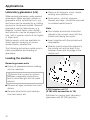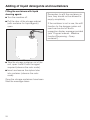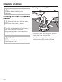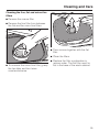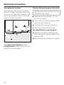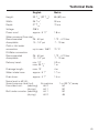
1
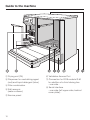
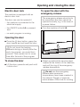
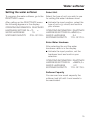
Operating Instructions
Laboratory glassware washer
G 7835
To prevent accidents
and machine damage
read these instructions
before
installation or use.
UV
M.-Nr. 06 214 820
Contents
IMPORTANT SAFETY INSTRUCTIONS . . . . . . . . . . . . . . . . . . . . . . . . . . . . . . . . . 4
Guide to the machine. . . . . . . . . . . . . . . . . . . . . . . . . . . . . . . . . . . . . . . . . . . . . . . 8
Opening and closing the door . . . . . . . . . . . . . . . . . . . . . . . . . . . . . . . . . . . . . . 11
Electric door lock . . . . . . . . . . . . . . . . . . . . . . . . . . . . . . . . . . . . . . . . . . . . . . . . . . 11
To open the door with the emergency release. . . . . . . . . . . . . . . . . . . . . . . . . . . . 11
Water softener . . . . . . . . . . . . . . . . . . . . . . . . . . . . . . . . . . . . . . . . . . . . . . . . . . . 12
Setting the water softener . . . . . . . . . . . . . . . . . . . . . . . . . . . . . . . . . . . . . . . . . . . 13
Filling the salt reservoir . . . . . . . . . . . . . . . . . . . . . . . . . . . . . . . . . . . . . . . . . . . . . 14
Salt indicator . . . . . . . . . . . . . . . . . . . . . . . . . . . . . . . . . . . . . . . . . . . . . . . . . . . . . 15
Automatic mobile unit recognition (AWK) . . . . . . . . . . . . . . . . . . . . . . . . . . . . . 16
Mobile unit coding . . . . . . . . . . . . . . . . . . . . . . . . . . . . . . . . . . . . . . . . . . . . . . . . . 16
Mobile unit coding strip . . . . . . . . . . . . . . . . . . . . . . . . . . . . . . . . . . . . . . . . . . 17
Setting mobile unit coding . . . . . . . . . . . . . . . . . . . . . . . . . . . . . . . . . . . . . . . . 17
Applications . . . . . . . . . . . . . . . . . . . . . . . . . . . . . . . . . . . . . . . . . . . . . . . . . . . . . 19
Loading the machine . . . . . . . . . . . . . . . . . . . . . . . . . . . . . . . . . . . . . . . . . . . . . . . 19
Height adjustable top basket. . . . . . . . . . . . . . . . . . . . . . . . . . . . . . . . . . . . . . . . . 21
Laboratory glassware (LG) . . . . . . . . . . . . . . . . . . . . . . . . . . . . . . . . . . . . . . . . . . 22
Adding of liquid detergents and neutralizers . . . . . . . . . . . . . . . . . . . . . . . . . . 23
Preparing the DOS dispensers . . . . . . . . . . . . . . . . . . . . . . . . . . . . . . . . . . . . . . . 23
Filling the containers with liquid cleaning agents. . . . . . . . . . . . . . . . . . . . . . . 24
Priming the liquid dispensing systems . . . . . . . . . . . . . . . . . . . . . . . . . . . . . . . . . 25
Dispensing system maintenance. . . . . . . . . . . . . . . . . . . . . . . . . . . . . . . . . . . . . . 25
External Dispensing systems. . . . . . . . . . . . . . . . . . . . . . . . . . . . . . . . . . . . . . . . . 25
Operation . . . . . . . . . . . . . . . . . . . . . . . . . . . . . . . . . . . . . . . . . . . . . . . . . . . . . . . 26
Switching on / selecting or changing operating level . . . . . . . . . . . . . . . . . . . . . . 26
Turning on . . . . . . . . . . . . . . . . . . . . . . . . . . . . . . . . . . . . . . . . . . . . . . . . . . . . . . . 26
To change operating level . . . . . . . . . . . . . . . . . . . . . . . . . . . . . . . . . . . . . . . . . . . 26
Starting a program . . . . . . . . . . . . . . . . . . . . . . . . . . . . . . . . . . . . . . . . . . . . . . . . . 27
Program sequence . . . . . . . . . . . . . . . . . . . . . . . . . . . . . . . . . . . . . . . . . . . . . . . . 28
Turning off . . . . . . . . . . . . . . . . . . . . . . . . . . . . . . . . . . . . . . . . . . . . . . . . . . . . . . . 28
To change or cancel a program. . . . . . . . . . . . . . . . . . . . . . . . . . . . . . . . . . . . . . . 29
Canceling a program . . . . . . . . . . . . . . . . . . . . . . . . . . . . . . . . . . . . . . . . . . . . . . . 30
Serial interface . . . . . . . . . . . . . . . . . . . . . . . . . . . . . . . . . . . . . . . . . . . . . . . . . . . 31
2
Contents
Cleaning and Care . . . . . . . . . . . . . . . . . . . . . . . . . . . . . . . . . . . . . . . . . . . . . . . . 32
Cleaning the filters in the wash cabinet . . . . . . . . . . . . . . . . . . . . . . . . . . . . . . . . . 32
Cleaning the coarse filter . . . . . . . . . . . . . . . . . . . . . . . . . . . . . . . . . . . . . . . . . 32
Cleaning the fine, flat and micro-fine filters . . . . . . . . . . . . . . . . . . . . . . . . . . . 33
Cleaning the drain pump and non-return valve . . . . . . . . . . . . . . . . . . . . . . . . . . . 34
Cleaning the water inlet filters . . . . . . . . . . . . . . . . . . . . . . . . . . . . . . . . . . . . . . . . 35
Cleaning the control panel. . . . . . . . . . . . . . . . . . . . . . . . . . . . . . . . . . . . . . . . . . . 35
Cleaning the exterior . . . . . . . . . . . . . . . . . . . . . . . . . . . . . . . . . . . . . . . . . . . . . . . 35
Drying unit (TA) - Cleaning and care . . . . . . . . . . . . . . . . . . . . . . . . . . . . . . . . . 36
Changing the coarse filter . . . . . . . . . . . . . . . . . . . . . . . . . . . . . . . . . . . . . . . . . . . 36
Replacing the HEPA-Filter . . . . . . . . . . . . . . . . . . . . . . . . . . . . . . . . . . . . . . . . . . . 37
Frequently asked questions . . . . . . . . . . . . . . . . . . . . . . . . . . . . . . . . . . . . . . . . 38
After sales service . . . . . . . . . . . . . . . . . . . . . . . . . . . . . . . . . . . . . . . . . . . . . . . . 39
INSTALLATION INSTRUCTIONS . . . . . . . . . . . . . . . . . . . . . . . . . . . . . . . . . . . . . 41
Caring for the environment . . . . . . . . . . . . . . . . . . . . . . . . . . . . . . . . . . . . . . . . . 42
Installation . . . . . . . . . . . . . . . . . . . . . . . . . . . . . . . . . . . . . . . . . . . . . . . . . . . . . . 43
Leveling the legs . . . . . . . . . . . . . . . . . . . . . . . . . . . . . . . . . . . . . . . . . . . . . . . . . . 43
Removing the lid (if necessary) . . . . . . . . . . . . . . . . . . . . . . . . . . . . . . . . . . . . . . . 43
Plumbing. . . . . . . . . . . . . . . . . . . . . . . . . . . . . . . . . . . . . . . . . . . . . . . . . . . . . . . . 44
Electrical connection . . . . . . . . . . . . . . . . . . . . . . . . . . . . . . . . . . . . . . . . . . . . . . 47
Technical Data . . . . . . . . . . . . . . . . . . . . . . . . . . . . . . . . . . . . . . . . . . . . . . . . . . . 49
3
IMPORTANT SAFETY INSTRUCTIONS
This machine conforms to current
safety requirements. Inappropriate
use can however lead to personal
injury and property damage. Read
the operating instructions carefully
before starting to use this machine.
Keep these instructions in a safe
place, and make them available to
future users.
Use
This machine is designed for
commercial use and for
specialized applications only, as
described in these Operating
Instructions. Do not use for purposes
other than those for which it was
designed, as this might be dangerous.
The programs are designed for
laboratory glassware which are
declared reprocessable. Regard the
information from the glassware
manufacturer.
Miele is not responsible for damages
caused by improper use.
The installation of this unit in non
stationary locations (e.g. ships)
must be performed by a qualified
installer or service agency, in strict
accordance with national and local
safety regulations and standards.
4
Please pay attention to the following
notes, to maintain safe procedures.
The machine should be
commissioned and then
maintained only by a Miele Service
Technician. Repairs by unqualified
persons could be dangerous.
Do not install the machine in an
area where a danger of explosion
or freezing may be present.
Be certain this appliance is
properly installed and grounded by
an authorized technician. To guarantee
the electrical safety of this appliance,
continuity must exist between the
appliance and an effective grounding
system. It is imperative that this basic
safety requirement be met. If there is
any doubt, have the electrical system
checked by a qualified technician. The
manufacturer cannot be held
responsible for damage or injury
caused by the lack of or inadequacy of
an effective grounding system (e.g.
electric shock).
A damaged machine is dangerous.
Turn off the machine immediately at
the main switch and call the Miele
Service Department.
Personnel operating the machine
should be trained regularly.
Children and untrained personnel must
not be allowed access to the machine
or its controls.
IMPORTANT SAFETY INSTRUCTIONS
Take care when handling liquids
such as detergents, neutralizing
agents, wetting agents and rinse aids.
These may contain irritant or corrosive
ingredients, acids or alkalis. Never use
any organic solvent, as the danger of
an explosion exists. The manufacturer’s
safety conditions must be observed
with all chemical agents.
,Wear protective gloves and
goggles.
The water in the machine must not
be used as drinking water.
After drying with the TA drying unit
open the door to allow the items
and inserts to cool.
Do not touch the heating elements
during or directly after the end of a
program, you could burn yourself. They
remain hot for some time after the end
of the program.
Never clean near the machine with
a water or a high pressure hose.
Before servicing, disconnect the
power supply by either removing
the fuse, unplugging the unit or
manually "tripping" the circuit breaker.
Do not sit or lean on the open door
or rest objects on it. This could
cause the machine to tip and be
damaged or cause an injury.
Be careful when sorting items with
sharp pointed ends. Position them
in the machine that you do not hurt
yourself or create danger for other
operators.
When using this machine regard
the high temperatures and be
especially careful not to scald or burn
yourself. When opening the door
bypassing the electrical lock, a danger
of burning, scalding or corrosion exists.
Let baskets and inserts cool before
touching them. Any water which may
remain in containers will be very hot
and must be emptied into the wash
cabinet.
5
IMPORTANT SAFETY INSTRUCTIONS
The following points should be
observed to assist in maintaining
quality standards, for critical lab
glassware, to protect patients, and to
avoid damage to the loads being
cleaned.
If the cleaning result is subject to
particularly stringent requirements
(e.g. chemical analysis, specialized
process), a regular quality control test
should be carried out by the user to
ensure that required standards of
cleanliness are being achieved.
If toxic or chemical substances are
possible in the wash water regard
the higher risk when interrupting a wash
cycle and opening the door. Always
check the seal of the door and the
function of the steam condensator.
Use only Miele approved cleaning
agents with this machine. Use of
unsuitable cleaning agents could
adversely affect the components of the
machine. Damages resulting from using
unsuitable cleaning agents are not
covered by the warranty.
Pre-treating (e.g. with cleaning
agents), certain soiling and
cleaning agents with a chemical
interaction, can cause foam. For
pre-treatment and / or cleaning only
use low-sudsing detergents and
disinfecting agents which have been
approved by Miele. Suds can have an
adverse effect on the cleaning process.
6
When a chemical additive is
recommended, the manufacturer of
the machine takes no responsibility for
the effect of the chemical on the
material of the items being cleaned.
Please be aware that changes in
formulation, storage conditions,
concentration etc, which may not be
publicized by the chemical producer,
can have a negative effect on the
cleaning result.
When using cleaning agents and
specialized products it is essential
that the manufacturer’s instructions are
followed. Only use the product for the
application described by the
manufacturer to avoid any material
damage or the occurrence of strong
chemical reactions.
The machine must only be
operated with water and the
recommended cleaning agents.
Organic solvents must not be used in
the machine, as there is the danger
under certain circumstances of
explosion. Although this is not the case
with all organic solvents, other
problems could arise with their use, for
example damage to rubber and
synthetic materials.
IMPORTANT SAFETY INSTRUCTIONS
In critical applications where very
high requirements have to be met,
it is strongly recommended that all the
relevant factors for the process, such
as cleaning agent, quality of water etc.
are discussed with the Miele
Applications Specialists.
The mobile units and special
inserts should only be used for
their specific application.
Empty any containers or utensils
before arranging them in the
machine.
Do not allow any remains of acids
or solvents, and in particular
hydrochloric acid, chloride solutions or
corroding ferrous material to get into
the wash cabinet. Similarly avoid any
materials with a corrosive effect. The
presence in compounds of any solvents
should be minimal.
Ensure that solutions or steam
containing hydrochloric acid do not
come into contact with the steel outer
casing of the machine to avoid any
corrosion damage.
Please follow the advice on
installation in these instructions
and the separate Installation
Instructions.
Using accessories
Only specific additional equipment
made by Miele should be
connected to this machine. Consult the
Miele Professional Group on the type
and application of such equipment.
Disposal of an old appliance
When discarding a lab washer,
disconnect it from the power
supply, remove the door to the wash
cabinet and cut off the power cord. For
environmental and safety reasons
ensure the machine is completely
drained of any residue water and
cleaning agent. (Observe safety
regulations and wear safety goggles
and gloves). Make the door lock
inoperative, so that children cannot
accidentally shut themselves in. Make
appropriate arrangements for the safe
disposal of the machine.
If the machine contains a tank system,
remove the water from the tank before
disposing of the machine.
The manufacturer cannot be held
responsible for any damage caused
through non-observance of these
Warning and Safety Instructions.
7
Guide to the machine
Electronic controls
8
Guide to the machine
a Display
with screen saver, background light
switches off automatically after
15 minutes, hit any key to turn the
background light on again.
b On/Off button (I-0)
c Cursor left
moves the cursor to the left:
– to the previous menu
– to the previous parameter
– to the previous input location
d Cursor right
moves the cursor to the right:
– to the next menu
– to the next parameter
– to the next input location
g Door switch
h Start button
– Starting a program
– Activating insert mode
– Confirming settings
– Confirming menu points, to get to
the respective submenu
i Stop button
– Canceling a program
– Leaving the insert window without
confirming
– Leaving a menu
j Optical interface
(for service technician)
k Program selector
Selecting programs 1-23
e Minus button
– program selection for programs
over 24
– going back pagewise in menus
– type in figures and letters
– change default settings, e.g.
service parameter
f Plus button
– program selection for programs
over 24
– going forward pagewise in menus
– type in figures and letters
– change default settings, e.g.
service parameter
9
Guide to the machine
a Drying unit (TA)
f Validation Access Port
b Dispenser for neutralizing agent
(red) and liquid detergent (blue)
g Connection for DOS-module G 60
for addition of a third dosing line
- rear side -
c Filter combination
d Salt reservoir
(water softener)
e Service panel
10
h Serial interface
- rear side (left upper side, behind
cover plate) -
Opening and closing the door
Electric door lock
The machine is equipped with an
electric door lock.
The door can only be opened if:
– the machine is connected to the
electrical supply,
– the ON/OFF button I-0 is pressed,
and
To open the door with the
emergency release
The emergency release should only
be used when the door cannot be
opened normally, e.g. in the case of
a power failure.
^ Turn the machine off with I-0.
– no wash program is running.
Opening the door
^ Press the 5 door button, grasp the
door handle and pull open the door.
,Do not touch the heating
elements during or directly after the
end of a program, you could burn
yourself. They remain hot for some
time after the end of the program.
To close the door
^ Lift the door upwards and push until
it clicks shut.
^ Reach up behind the service panel,
located at the bottom of the machine,
and pull the ring of the emergency
release downwards.
,Do not use the emergency
release when excessive
temperatures have been reached in
the cabinet. Danger of pressure
wave release. Allow time for cooling.
11
Water softener
Before using the machine for the first
time, the water softener should be
programmed. The water needs to be
softened to avoid calcium deposit
buildup on the items being cleaned and
in the machine itself.
To ensure a steady supply of soft water:
1. Make sure the water softener is
programmed correctly.
2. The salt reservoir must be filled with
reactivation salt.
– If the water hardness is below 70
ppm (4 gr/gal) the reservoir does not
need to be filled. Once the machine
has been set accordingly the
reactivation will no longer occur and
the salt refill warning will not appear.
The machine is factory set to a water
hardness level of 340 ppm (19 gr/gal).
Your local water authority will advise
you of the water hardness in your area.
For fluctuating levels (e.g. 140 to
310 ppm) set the water softener to the
highest setting (in this example to 310
ppm).
Important: The built-in water softener
has settings from 18 ppm to
1080 ppm.
12
For future servicing it is useful to make
a note of your water hardness level.
^ Enter the local water hardness level
here:
ppm
Water softener
Setting the water softener
Select Unit
To program the water softener, go to the
REACTIVATE menu.
Select the type of unit you wish to use
for setting the water hardness level:
After calling up the REACTIVATE menu
the following appears in the display:
^ Activate the input position, select the
type of unit e.g. mmol/l and confirm
your choice.
OPERATING INFORMATION REACTIVATE
HARDNESS SETTING IN >°D
<
WATER HARDNESS
19
SOFTENER CAPACITY
210 L OF 210 L
OPERATING INFORMATION REACTIVATE
HARDNESS SETTING IN >MMOL/L<
WATER HARDNESS
3.4
SOFTENER CAPACITY
170 L OF 210 L
Enter Water Hardness
After selecting the unit the water
hardness value is in the display.
^ Activate the input position, set the
hardness level and confirm your
selection.
OPERATING INFORMATION REACTIVATE
HARDNESS SETTING IN >MMOL/L<
WATER HARDNESS
0.2
SOFTENER CAPACITY
170 L OF 700 L
Softener Capacity
You can see how much capacity the
softener had left until it next needs to
be reactivated.
13
Water softener
Filling the salt reservoir
Only special, coarse-grained
reactivation salt* should be used in
this machine.
*Available from Miele’s Professional
Customer Service Department.
Please see back page for more
information.
Do not use other types of salt, e.g. table
salt, agricultural or gritting salt. These
could contain components which are
insoluble in water and could damage
the water softener. If in doubt, consult
Miele’s Professional Department.
The salt reservoir holds approx. 2.5 kg
of salt.
,Inadvertently filling the salt
reservoir with detergent will damage
the water softener.
Before filling, make sure that you are
using reactivation salt.
^ Remove the bottom basket from the
machine.
^ Unscrew the salt reservoir cap.
Before filling the salt reservoir with
reactivation salt for the first time fill it
with approx. 2.5 liters of water.
14
^ Place the funnel provided in place.
^ Carefully fill the reservoir with salt.
Displaced water will run out as it is
being filled.
^ Wipe any residual salt off the screw
threads on the socket.
^ Screw the cap on firmly.
^ Immediately after this step: Run the
"REMOVE SALT" program to remove
any traces of salt from the cabinet.
Note: There may be a delay before the
"REMOVE SALT" program starts due to
the reactivation of the water softener.
Water softener
Salt indicator
Replenish the reactivation salt when the
message ADD SALT is displayed.
Reactivation takes place automatically
during a program.
During this process the message
REACTIVATION is displayed.
15
Automatic mobile unit recognition (AWK)
In operating level C the optional
Automatic mobile unit recognition
(AWK) feature attributes a fixed
program place to a mobile unit with
valid coding.
Program places 1-15 are reserved for
the AWK automatic mobile unit
recognition.
Mobile unit coding
The unit coding (on the mobile unit)
and the program place with the
corresponding program (in the
"Profitronic" electronic control unit)
must be matched up.
After a coded mobile unit has been put
in the machine and the door is closed,
the control unit selects the allocated
program. Press 6 to start the program.
^ Each mobile unit must be coded
before being used for the first time.
See "Coding the mobile unit".
^ The wash program through which the
mobile unit is coded has to be
assigned to the relevant program
place (operating level D, see the
"System function - Selector
Organization" section in the
Programming Manual).
Important!
Before starting the program with the
"Start" button 6, check if the
program needed for this mobile unit
is displayed.
Insufficient wash results may occur!
Always check that programs for
mobile units with AWK (on fixed
program places) are not exchanged.
16
The AWK assigns a program place to a
mobile unit. The mobile units must be
coded with a magnetic strip via a Bit
combination. In operating level C the
only program available for a coded
mobile unit is the one assigned to the
corresponding program place.
Coding is affected through 5 Bits:
– Bit 1 through 4 define the mobile unit
code,
– Bit 5 serves as a control (Parity-Bit).
Automatic mobile unit recognition (AWK)
Mobile unit coding strip
Setting mobile unit coding
15 different codes can be set. They are
assigned to program places 1 to 15.
To set or alter the coding of a mobile
unit with the AWK proceed as follows:
Under "System function, Selector switch
organization" the matching programs
have to be put into the first 15 program
places.
Program Bit 1
location
1
2
3
4
5
6
7
8
9
10
11
12
13
14
15
0
I
0
I
0
I
0
I
0
I
0
I
0
I
0
I
Bit 2
Bit 3
Bit 4
Bit 5
ParityBit
0
0
I
I
0
0
I
I
0
0
I
I
0
0
I
I
0
0
0
0
I
I
I
I
0
0
0
0
I
I
I
I
0
0
0
0
0
0
0
0
I
I
I
I
I
I
I
I
0
I
I
0
I
0
0
I
I
0
0
I
0
I
I
0
^ Unscrew the track with AWK (allen
wrench) and remove from the
retainer.
The coded total must be an even
number.
If the summary totals an odd number,
the message CHECK MOBILE UNIT
RECOGNITION appears. In both cases
the program cannot be started. The
mobile unit recognition must be re-set.
^ Remove the magnetic strip from the
track.
17
Automatic mobile unit recognition (AWK)
^ Set the program place coding.
^ Place the track in the holder of the
mobile unit and screw firmly in place.
^ Put the magnetic strip back in the
track.
Important:
The magnetic strip must be placed
in the track so that the Bit coding set
according to the chart is visible
through the round windows in the
track.
18
The magnetic strip on the G 7835
must have grey magnets.
Applications
The machine can be fitted with a variety
of mobile units, baskets and inserts,
depending on the cleaning application
in question.
The diversity of these units and inserts
is so great that it is not possible to
illustrate them all or give detailed
instructions on their use here. For
example there are inserts for direct
spraying or rinsing glassware which
contain internal surfaces, tubes and
pipes that need stringent cleaning.
Preparing the items for
cleaning
– Are the items to clean correctly
sorted and connected?
– Are the spray arms clean and can
they rotate freely?
– Is the filter combination free of
coarse soiling?
– Is the adapter to the water inlet in
place?
Loading the machine
– Are the spray arms correctly
connected?
Removing excess soils
– Are the detergent and neutralizer
containers full?
^ Empty all containers before loading
them into the machine.
,Ensure that no acid or solvent
residues, especially hydrochloric
acid or chlorides get into the wash
cabinet.
19
Applications
Note
^ Load the items to be washed so that
water can access all surfaces. This
ensures that it is properly cleaned.
^ Do not place items to be cleaned
inside other pieces where they may
be concealed.
^ Hollow vessels such as beakers,
measuring cylinders, flasks, etc.
should be inverted and placed in the
correct inserts so that water can flow
in and out unrestricted. A cover net
can be used to reduce the risk of
movement during the wash process.
^ Use a cover net (e.g. an A 2) or a
mesh tray for small items to secure
lightweight items to prevent them
from blocking the spray arms or
being caught up with the magnetic
strip on the automatic mobile unit
recognition system.
^ Deep based items should be placed
at an angle to allow water to run off
easily.
20
^ Tall, narrow pieces should be placed
in the center of the baskets. This
ensures good water coverage.
^ Mobile units and baskets with an
adapter must engage correctly.
^ The spray arms must not be blocked
by tall items or items which hang
down in their path. If necessary,
manually rotate the arms to test.
Select mobile units, baskets and
inserts appropriate for the
application.
Applications
Spring adapter water connection
Height adjustable top basket
Make sure that the spring adapter for
water connection engages correctly
when a basket or injector unit is
inserted in the machine. It must be 3/16"
(4-5 mm) higher than the water
connection inlet in the machine. If this is
not the case, adjust the adapter.
The upper basket can be adjusted
above and below the middle position
by 13/16" (2 cm).
Depending on the position of the upper
basket and usage of an insert, items of
the following height can be
accommodated in the baskets:
^ Loosen the lock ring.
^ Push up the adapter (4-5 mm higher
than the water connection inlet in the
machine) and tighten up the lock
ring.
Example upper basket O 190/1 and
lower basket U 874
Upper
basket
position
Upper
basket
height
Lower
basket
height
Upper
max.
7 7/ 8"
(20 cm)
max.
9 7/16"
(24 cm)
Middle
max.
8 11/16"
(22 cm)
max.
8 11/16"
(22 cm)
Lower
max.
9 7/16"
(24 cm)
max.
7 7 / 8"
(20 cm)
To adjust the upper basket
^ Pull out the top basket, lift from the
runners and remove.
^ Unscrew the knurled nuts (roller
bearings) on both sides of the basket
with a suitable wrench, reposition as
required.
21
Applications
Laboratory glassware (LG)
Wide necked glassware, wide necked
erlenmeyer flasks and petri dishes or
glassware with a cylindrical form, e.g.
test tubes can be cleaned by a rotating
spray arm inside and outside. General
glassware used in laboratories, e.g.
beakers, conical flasks, petri dishes,
test tubes etc. can be arranged in full
size, half or quarter inserts at the higher
or lower level.
Mobile injector units are available for
direct injection spraying of narrow
necked flasks, pipettes etc.
The following instructions relate only to
basic preparation and loading of
glassware.
^ Remove all stoppers, corks, labels,
sealing wax residues, etc.
^ Small parts - such as stoppers,
faucets and taps - should be secured
in suitable basket inserts.
Note
^ Petri dishes and similar should be
placed in the correct insert with the
soiled side facing the center.
^ Insert pipettes with the pointed end
downwards.
^ Quarter inserts should be placed in
the mobile unit with at least 3 cm
between them and the edge of the
mobile unit.
Loading the machine
Removing excess soils
^ Empty all glassware before loading
into the machine.
,Ensure that no acid or solvent
residues, especially hydrochloric
acid or chlorides get into the wash
cabinet.
^ Remove all agar residues from petri
dishes.
^ Remove blood clots and residues
from test tubes, etc.
22
E 350 Injector unit 1/1
(E 380 with connection to TA)
Sufficient for narrow neck laboratory
glassware with 32 (33) jets/clips.
Adding of liquid detergents and neutralizers
,Use only cleaning detergents
and neutralizers specially designed
for lab washers and regard the
application recommendations of the
manufacturer!
This automatic cleaning machine is
fitted with 2 dispensers as standard:
– Dispensing system DOS 1 (blue) to
dispense liquid cleaning agent. The
dosing rate is 120 ml/min.
– Dispensing system DOS 3 (white) to
dispense (acid) media such as
neutralizing agent or rinsing agent.
The dosing rate is 20 ml/min.
Additional DOS modules (optional):
– Dispensing system DOS 2 (red) to
dispense acid media such as
neutralizing agent.
The dosing rate is 105 ml/min.
– Dispensing system DOS 4 (green) to
dose a low-foam disinfecting agent
suitable for machine washing, or a
further cleaning agent. The dosing
rate is 120 ml/min.
The amounts of cleaning agent
required, depending on the application
chosen for this machine, are dispensed
through these dispensing systems.
Preparing the DOS dispensers
The agents can be filled into 5 l plastic
containers, which are color coded for
the relevant dispensing system.
When first commissioning, or when the
message "FILL CONTAINER DOS 1"
and/or DOS 2, 3, 4 flashes in the
display after switching on or at the end
of a program, fill the storage container
with the correct detergent or neutralizer.
If the message "CHECK DISPENSING
SYSTEM 1" and/or DISPENSING
SYSTEM 2, 3, 4 flashes in the display,
(the program has been automatically
put on hold), check the storage
container and the dispensing hoses
and refill if necessary.
When first commissioning or when
the message "CHECK THE
DISPENSING SYSTEM... ", appears,
start the DOS-FILL program to prime
the dispensing system (see "Priming
the liquid dispensing system").
,Exercise caution when handling
detergents! These may contain
acids, alkalis or disinfectants.
Follow the instructions and relevant
safety procedures carefully.
Wear protective gloves and goggles.
23
Adding of liquid detergents and neutralizers
Filling the containers with liquid
cleaning agents
^ Turn the machine off.
^ Pull the door of the storage cabinet
(with container for liquid agents)
open.
^ Take the storage container out of the
unit, open it and fill with the agent
required (observe the color code).
^ Insert and secure the siphon tube
into container (observe the color
code).
Once the storage containers have been
filled the message clears.
24
Remember to refill the containers in
time, they should not be allowed to
empty completely.
If the container is not in use, the refill
function for the dosage system not
used can be shut off and a
respective display message avoided
(see "Program manual - Machine
function/Dispensing - Query
container").
Adding of liquid detergents and neutralizers
Priming the liquid dispensing
systems
Dispensing system
maintenance
Before the machine is first used, and
later if one or more containers has been
allowed to empty, the dispensing
system(s) for liquid media must be
vented.
To ensure safe function the following
maintenance should be carried out by a
Miele Service Technician at specified
intervals.
^ Press the ON/OFF I-0 button.
Every 12-18 months:
^ Select operating level "B".
Inspect the hoses in the dispensing
system(s). Replace if necessary.
^ Select from the following as required:
Program DOS 1-FILL
Program DOS 3-FILL
(see under "Operation - B. Free
program selection").
Optional:
Program DOS 2-FILL
Program DOS 4-FILL
(if DOS 2 and/or DOS 4 pumps have
been built in).
External Dispensing systems
If external pumps are to be used for
dispensing liquid detergent, please
inform the Miele Technical Service
Department. The notes in the
Programming Manual under "Machine
functions" must be observed.
^ Press the "Start" 6 button.
The DOS-FILL Service Program are
allocated by default to program
places 58-61, but they can be
allocated to other program places.
25
Operation
Power switch
To change the operating level
(with "emergency cut-off function") set
to I-ON.
^ Press 1 and 2 at the same time.
Operating levels A B C D will appear
in the display.
When switching on, selecting or
changing the operating level there are
four operating levels available:
A = Fixed program / Programs with free
access
B = Free program selection
C = AWK – Automatic mobile unit
recognition (program selection via
mobile unit coding)
D = Programming / free program
selection / change code (see
"Programming manual")
^ Select the operating level you want
using the 1 or 2 keys.
^ Press 6 to confirm selection.
^ Enter code when requested by the
display.
The code is set by default to >0000<.
^ Press the "Start" button 6.
[0000] appears.
^ Enter numbers using the 4 and 3
keys.
Turning on
^ Select number position with the 1 or
2 key.
^ Open the water valves (if turned off).
^ To confirm code press 6.
^ Press the ON/OFF I-0 button.
In operating levels A, B and D the most
recently selected PROGRAM NAME
appears and in operating level C
"AUTOMATIC MOBILE UNIT
RECOGNITION" is displayed.
If you enter it incorrectly: FALSE CODE,
ENTER AGAIN will appear in the
display.
^ Close the door.
Selecting or changing your own
code
The factory set code can be
changed (see "Programming Manual
- System function").
Code 1 for levels ABC
Code 2 for levels ABCD
26
Operation
Starting a program
You can find detailed and important
information regarding the Miele
default programs in the program
chart of the supplied Programming
Summary.
A. Fixed program
To utilize access level "A", fixed
programs must be assigned for access.
See the Programming Manual section
on "System Functions" for details on
assigning programs. Once programs
are assigned to access level "A" they
can be operated in the following
manner.
^ Select operating level "A".
^ Check in the display that the program
shown is the one required. If several
fixed programs have been made
freely accessible, select the one
required using the program selector.
^ Press the "Start" 6 button.
B. Free program selection
^ Select operating level "B".
With operating level "B" there are three
possibilities for program selection.
1. Program places 1 - 23 can be
selected using the Program selector.
^ Turn the program selector to the
required program.
The program name appears in the
display.
2. Programs above place 24 are
selected using the 4 and 3 keys.
^ Turn the program selector to 24.
^ Press 4 (scrolls upwards) or 3
(scrolls down) until the required
program is shown.
3. The PROGRAM SURVEY menu lists
all stored programs. A program can be
selected from this menu.
^ Select PROGRAM SURVEY with 1
and confirm with 6.
^ Select a program using 1 or 2.
^ Press 6 to confirm selection.
This exits the PROGRAM SURVEY, and
the selected program is shown in the
display.
After selecting one of the three options
above:
^ Press the "Start" 6 button, the
program proceeds.
For further information on program
selection see "Operating Level B" in the
"Programming Manual".
27
Operation
C. Automatic mobile unit recognition
(AWK)
^ Select operating level "C".
^ Push the coded mobile unit into
place (See Setting mobile unit
coding").
^ Close the door.
Important:
It is absolutely essential to check
that the program required for this
mobile unit is the one shown in the
display, before starting the program
by pressing the "Start" button.
Otherwise inadequate cleaning
could result.
Please make sure, that the places
assigned for programs using AWK
(Automatic mobile unit recognition)
are not changed at random.
^ Press the "Start" 6 button.
Document any program and dosage
changes.
Program sequence
After being started the program will
proceed automatically. It is finished
when PROGRAM END appears in the
display and the background lighting
flashes (press any button to switch off
the flashing lights).
The flashing lights can be permanently
switched off. See "Programming Manual
- System Functions".
Detailed information on program
sequences is given in the appendix
of the "Programming Manual".
The display background lighting
goes out automatically after
approximately 15 mins. To bring it
back on again press one of the
touch buttons.
Turning off
^ Press in and release the ON-OFF, I-0,
button.
^ Turn off the water valves.
28
Operation
To change or cancel a program
2. In operating levels A or C
If the "Start" button 6 has already been
pressed:
Select operating level B or D.
(Note: you will be asked for your code.)
Proceed as follows:
1. In operating levels B or D
^ Press 1 and 2 at the same time.
Operating levels A B C D will appear
in the display.
^ Press the "Stop" 7 button (the
program is interrupted).
>CANCEL< OR >CONTINUE<
appears in the display.
^ Select >CANCEL< with the 1 cursor
button. (The cursor > < flashes.)
^ Press the "Start" 6 button (the
program is cancelled and the water
is drained). DRAIN WATER appears
in the display.
^ After the water has been drained the
required program can be selected
and started again.
^ Select operating level B or D with the
1 or 2 key.
^ Press 6 to confirm selection.
^ Enter code when requested by the
display.
^ Press the "Start" button 6.
[0000] appears.
^ Enter numbers using the 4 and 3
keys.
^ Select number position with the 1 or
2 key.
^ To confirm code press 6.
If you enter it incorrectly: FALSE CODE,
ENTER AGAIN will appear in the
display.
^ In operating levels B or D proceed as
described under 1.
29
Operation
Cancelling a program
2. In operating levels A or C
If a program needs to be interrupted or
cancelled:
^ Press the I-0 button. The program is
interrupted.
1. In operating levels B or D
^ Press the "Stop" 7 button (the
program is interrupted).
>CANCEL< OR >CONTINUE<
appears in the display.
^ Open the door.
Important for machines with a
clean and an unclean side:
With the setting "WITHOUT DOOR
INTERLOCK" - "YES" the doors on
either the clean or unclean side can
be opened. If the setting "WITHOUT
DOOR INTERLOCK" - "NO" is
selected, only the door on the
unclean side can only be opened at
this stage.
,Caution! Water and items in the
machine may be hot. There is a
danger of burning or scalding.
^ Arrange the parts securely observing
any protective measures.
^ Close the lift door.
^ Press the "Start" 6 button. The
program continues.
Select operating level B or D.
(Note: you will be asked for your code.)
Proceed as follows:
^ Press the On-Off I-0 button. The
machine continues.
^ Press 1 and 2 at the same time.
Operating levels A B C D will appear
in the display.
^ Select operating level B or D with the
1 or 2 key.
^ Press 6 to confirm selection.
^ Enter code when requested by the
display.
^ Press the "Start" button 6.
[0000] appears.
^ Enter numbers using the 4 and 3
keys.
^ Select number position with the 1 or
2 key.
^ To confirm code press 6.
If you enter it incorrectly: FALSE CODE,
ENTER AGAIN will appear in the
display.
^ In operating levels B or D proceed as
described under 1.
30
Serial interface
Each machine can be supplied with a
5 m long interface cable for data
transfer between the Profitronic system
and an external report printer or PC.
The serial interface is RS 232
compatible.
Various printers can be used as
external printers:
– Epson-compatible sign-set
– HP LaserJet
For the interface configurations see
"PC/Printer Function" in the
"Programming Manual".
The address of the 9-pole pin sub-D
plug of the serial interface cable:
5GND (ground)
3TXD (transmit)
2RXD (receive)
1-4-6 (linked)
7-8 (linked)
The report print-out documents the
time along with the:
– Date and machine number,
– Program start (with program place
and program name),
– Dispensing system with dispensing
temperature and dispensing
concentration for each program
block,
– Effective time successfully
completed with required temperature
reached and time for each program
block,
– Achieved temperature and time of
day required in the drying sequence
– All faults (e.g. water inlet blocked),
– All manual interventions (start, stop,
interruptions to power supply),
– Program end.
A standard null-modem or LapLink
cable can be connected.
The extension cable to the printer/PC
must not exceed 13 m.
Please note the following when
connecting a printer or PC:
– Only use an industry-standard PC or
printer.
– When installing the machine take the
dimensions of the printer/PC into
account.
31
Cleaning and Care
,Wear protective gloves and
Cleaning the coarse filter
goggles when cleaning this
machine.
Cleaning the filters in the wash
cabinet
,The machine must not be used
without all the filters in place!
The filter combination in the base of
the wash cabinet should be
inspected regularly and cleaned if
necessary.
,Caution!
Watch out for sharp objects which
could cause injury.
32
^ Press the two tabs together, remove
and clean the coarse filter.
^ Put the clean filter back in position
and press until it clicks in place.
Cleaning and Care
Cleaning the fine, flat and micro-fine
filters
^ Remove the coarse filter.
^ Remove the fine filter from between
the flat and the micro-fine filters.
^ Then remove together with the flat
filter.
^ Clean the filters.
^ To unscrew the micro-fine filter, grasp
the two tabs and turn twice
counterclockwise.
^ Replace the filter combination in
reverse order. The flat filter must lie
flat in the base of the wash cabinet.
33
Cleaning and Care
Cleaning the drain pump and
non-return valve
The drain pump is beneath the
non-return valve (see arrow).
If water has not been pumped away at
the end of a program the drain pump or
the non-return valve may be blocked.
^ Remove the filter combination out of
the wash cabinet.
^ Tilt the locking clamp to the side.
^ Before refitting the non-return valve,
check that the drain pump is not
blocked. Spin the propeller several
times in both directions to check for
obstructions.
^ Pull out the non-return valve and
rinse well under running water.
34
^ Carefully refit the non-return valve
and secure it with the locking clamp.
Refit and lock the filter in place.
For safety the load should be
washed again.
Cleaning and Care
Cleaning the water inlet filters
Filters are incorporated in to the intake
hose attached to the washer’s shut off
valve. The filters must be cleaned when
dirty or insufficient water flows into the
wash cabinet.
,The plastic valve housing on the
intake hose contains electrical
components and should not be
immersed or run through water.
Cleaning the filter:
^ Disconnect the machine from the
power supply (unplug it or "trip" the
circuit breaker).
^ Carefully remove the rubber seal.
Turn off the water valve. Unscrew the
water inlet hose.
^ Screw the intake hose back on the
water valve, checking that it is not
cross-threaded.
^ Slowly turn on the valve and test for
leaks. If there is a leak, screw the
connections on more tightly.
Cleaning the control panel
^ Only clean the control panel with a
damp cloth.
,Do not use too much water when
cleaning the controls. Water could
penetrate into the electronics and
cause damage.
Do not use abrasive, glass or all
purpose cleaners! They will damage
the surface.
Cleaning the exterior
^ Stainless steel surfaces can be
cleaned using a non-abrasive
stainless steel cleaner. To help
prevent resoiling, a conditioner for
stainless steel can also be used.
Apply sparingly with even pressure.
,Do not use any cleaner
containing ammonia or thinners.
Never use abrasive cleaners,
scouring pads, steel wool or caustic
(oven) cleaners on the machine.
They will damage the surface.
^ Remove the filters using needle nose
pliers. Rinse the large area filter, 1, and
fine filter, 2, under running water, and
replace if necessary.
^ Return filters and seal. Make sure
they are seated correctly.
35
Drying unit (TA) - Cleaning and care
Changing the coarse filter
The coarse filter should be changed
when the message "CHANGE TA
COARSE" flashes in the display.
^ Open the door of the storage cabinet.
^ Change the coarse filter. The soft
filter side must face the front with the
part imprinted.
^ Take out the metal perforated plate at
the drying unit.
^ Replace the perforated plate by
positioning it at the base and
pressing it into place at the top.
After the coarse filter has been
changed set the operating timer to
zero, as follows:
^ Select the program CHANGE TA
COARSE (see "Operating - B. Free
program selection).
^ Press the "Start" 6 button.
When the service program has ended,
a message appears in the display.
^ Confirm the instruction >CONTINUE<
with 6.
36
Drying unit (TA) - Cleaning and care
Replacing the HEPA-Filter
The HEPA filter should be changed
when the message "CHANGE FINE
FILTER" flashes in the display.
,This filter should only be
changed by a Miele Service
Technician.
A smooth operation of the machine can
only be achieved if an original "Miele"
HEPA-filter is used.
After the HEPA filter has been changed
set the operating timer to zero, as
follows:
^ Select the program CHANGE TA
FINE (see "Operating - B. Free
program selection).
^ Press the "Start" 6 button.
When the service program has ended,
a message appears in the display.
^ Confirm the instruction >CONTINUE<
with 6.
The service programs CHANGE TA COARSE and FINE were set by
default to program places 62 and
63, but they can be moved to other
program places. See "System
functions" in the Programming
Manual.
37
Frequently asked questions
With the aid of the following guide,
minor problems can be fixed without a
service call.
Repairs should only be carried out by a
qualified and trained person in
accordance with local and national
safety regulations. Unauthorized repairs
could cause personal injury or machine
damage. In the event of any problems
which cannot be corrected, please
contact the Miele Technical Service
Department.
Messages regarding the operating
status of the machine and fault
messages are shown in the display.
The error message table is
supplied in the Programming
manual under "Messages".
Heater limiter
This machine has a resettable heater
limiter which will shut off the elements in
the event of over-heating. This could be
caused for example, if large articles
cover the heating elements or if the
filters in the wash cabinet are blocked.
If the message "CHECK WASH
CABINET HEATING" is displayed (water
has not heated up in the wash cabinet
and the program takes too long):
^ Isolate and correct the cause of the
problem.
^ Remove the service panel (see
"Electrical connection").
^ Press the red-brown RESET button on
the temperature sensor on the right
side.
If this switch trips repeatedly, contact
the Miele Technical Service
Department before using the
machine further.
38
After sales service
Should you have any difficulties please
contact the Miele Technical Service
Department.
See back cover for addresses.
^ Please quote the model and serial
number of your machine.
This information can be found on the
data plate (see also "Electrical
connection").
39
40
INSTALLATION INSTRUCTIONS
Caring for the environment
Disposal of the packing
materials
The cardboard box and packing
materials protect the appliance during
shipping. They have been designed to
be biodegradable and recyclable.
Ensure that any plastic wrappings,
bags etc. are disposed of safely and
kept out of the reach of children.
Danger of suffocation! Please recycle.
42
Disposal of an old appliance
Old appliances may contain materials
that can be recycled. Please contact
your local authorities about recycling in
your area.
Ensure that the appliance presents no
danger to children while being stored
for disposal. See "Important Safety
Instructions".
Installation
Please refer to the installation
diagram supplied with the machine.
,Furniture and fittings installed
near the machine must be of a
commercial standard, able to
withstand the effects of steam.
Installation options
– Free-standing
– Slot-in, next to other machines or
furniture or in a suitable space. The
space must be at least 35 7/16" (90
cm) wide and 29 7/16" (70 cm) deep.
– Undercounter
The machine can be installed under a
continuous counter or sink drain.
The niche must be at least:
Width 35 7/16" (90 cm)
Depth 29 7/16" (75 cm)
Height 32 5/16" (82 cm).
The labwasher can be built into a
recess of 32 5/16" (82 cm) high by
removing the lab washer top.
Leveling the legs
Any unevenness in the floor can be
compensated for and the height of the
machine raised or lowered by adjusting
the four screw feet.
When the feet are screwed in, the
machine can be moved back and forth
on its rollers.
Removing the lid (if necessary)
^ Open the door.
^ Remove the fixing screws on both
sides using a cross slotted
screwdriver.
^ Pull the machine lid approx. 5mm
forwards, lift upwards and remove.
Protecting the countertop
(depending on model)
Important for machines with steam
condenser (depending on model):
To prevent steam damage to the
countertop, adhere the protective foil
9 13/16" x 22 13/16" (25 x 58 cm)
underneath the countertop near the
steam condenser.
Depending on the requirements for
installation, the following kit can be
ordered from the Miele Technical
Service Department.
Cover plate (protects the countertop)
The underside of the countertop is
protected from steam damage by a
stainless steel plate.
43
Plumbing
Water inlet
,Water in the machine is not
suitable for drinking.
^ The machine must be connected to
the water supply in accordance with
local and national regulations.
^ The washer is constructed so it may
be connected to a supply without an
extra non-return valve, unless
required by code.
^ Acceptable water pressure (flowrate)
is 10 - 145 psi. However the
recommended pressure is 25 - 60 psi
If the water pressure is below 30 psi,
the fill time will take longer.
If the water pressure is not in the
range of 10 - 145 psi the message
CHECK WATER INLET will be
displayed. Contact the Miele
Technical Service Department.
^ Water valves with 3/4" (2 cm) male
hose thread are to be provided on
site. They should be easily
accessible so the water supply can
be turned off if necessary.
^ The inlet hoses are 5 1/2 feet (1.7 m)
long, terminating in a 3/4" ( 2 cm)
female hose thread. The water inlet
filters in the threads must not be
removed.
^ Large surface area filters are
enclosed in the kit supplied with the
machine.
Install these filters between the water
valve and the water inlet hose (see
illustration in "Cleaning the water inlet
filters"). The large surface area filter
for DI water is made from stainless
steel and can be recognized by its
matte surface.
^ The machine is supplied standard to
be connected to a cold (coded blue)
and a hot (coded red) water supply
to a maximum temperature of 158 °F
(70 °C).
Connect the water intake hoses to the
cold and hot water faucets. The
steam condenser inlet hose (without
waterproof connector) should be
connected to the cold water supply,
using the adapter supplied
If no hot water supply is available,
the hot water inlet hose marked red
should also be connected to a cold
water supply by a y-adapter.
For a DI-water connection (H2O
pure), see next page.
44
,Do not cut the inlet hose or
damaged in any way.
^ See also the installation diagram
supplied.
Plumbing
DI-Water connection
The machine comes with a standard
connection for a pressurized DI system.
The recommended water pressure (flow
rate) is 25 - 60 psi however, water
pressure of 10 - 147 psi is acceptable.
^ The DI pressure-tested hose (marked
"H2O pure") with a 3/4" (2 cm) hose
thread must be connected to the
on-site water valve for DI purified
water.
,If the DI water connection is not
used, the electronics must be
reprogrammed by a Miele
technician. The water intake hose
remains at the rear side of the
machine.
45
Plumbing
Drainage
^ The drainage system is fitted with a
non-return valve which prevents dirty
water from flowing back into the
machine via the drain hose.
^ The machine should preferably be
connected to a separate drainage
system onsite.
If separate drainage is not available
contact your Miele application
specialist for advice.
The onsite drain connection point
should be located between 1 ft.
(0.3 m) and 3 ft. (1 m) above the
lower edge of the machine.
If it is lower than 1 ft. (0.3 m), lay the
hose in a curve at a height of at least
1 ft. (0.3 m).
The drainage system must be able to
take a minimum drainage flow of
16 l/min.
^ The drain hose is approx. 5 ft. (1.5 m)
long, is flexible and has an internal
diameter of 7/8 in (22 mm). It must not
be shortened. Hose clamps are
supplied for securing it in position.
^ A longer drain hose (up to 13 ft. [4 m]
long) is available to order from the
Miele Technical Service Department.
^ The drainage system must not
exceed 13 ft. (4 meters).
^ See the supplied installation diagram.
^ Two drain hoses are used, one for the
wash cabinet and one for the steam
condenser drain.
46
Electrical connection
,All electrical work must be
carried out by a qualified electrician
in accordance with local and
national safety regulations.
The machine comes equipped for
connection to a 208 V, 60 Hz, 3 phase
power supply. It is equipped with a 6 ft.
(1.8 m) long, 12/4 AWG power cord,
without a plug. A plug, rated for the
required power which will fit the
receptacle, is to be supplied by the
electrician doing the installation. It
should be connected to the main power
supply.
Voltage:
208 V, 3 phase
Frequency:
60 Hz
Rated Load:
6 kW
Circuit breaker:
3 x 20 A
It can be converted to use a single
phase power supply in accordance
with the conversion and wiring diagram.
The cord must be changed from a 12/4
AWG to a 10/3 AWG. Contact Miele
Technical Service for more information.
Voltage:
208 V, 1 phase
Frequency:
60 Hz
Rated Load:
6 kW
Circuit breaker:
2 x 30 A
^ A damaged power cord must only be
replaced with a genuine Miele cord
by a Miele service technician.
WARNING
THIS APPLIANCE MUST BE
GROUNDED
Black : connect to L1 (hot)
Red:
connect to L2 (hot)
White: connect to L3 (hot)
Green: connect to GND (ground)
47
Electrical connection
Grounding the machine
The machine must only be operated
with the voltage, frequency and fusing
shown on the data plate located on the
rear of the machine, and on the plinth
(behind the service panel).
Remove the service panel and plinth
,Disconnect the machine from the
main electrical supply.
^ Remove the fixing screws, a, from
the service panel.
^ Take hold of the service panel at both
sides and pull upwards.
^ Unscrew plinth facing (screws b).
^ Remove plastic protective cap.
Re-assembling the service panel
^ Replace the plastic protective cap,
plinth facing and service panel in the
reverse order.
^ See the supplied installation diagram.
The conversion diagram and the
wiring diagram is secured to the inner
side of the service panel.
48
Technical Data
English
7
Metric
5
Height:
33 /16" (32 /16")
85 (82) cm
Width:
35 7/16 "
90 cm
Depth:
27 9/16 "
70 cm
Voltage:
208 V
Power cord
approx. 5’ 11"
1.8 m
Water pressure (flow rate):
Recommended
25 - 60 psi
Acceptable
10 - 147 psi
1.72 - 4.13 bar
.7 - 10 bar
Cold or Hot water
connection
up to max. 158°F
70 °C
DI-Water connection
Recommended
Acceptable
25 - 60 psi
10 - 147 psi
1.72 - 4.13 bar
.7 - 10 bar
Delivery head:
min. 12"
max. 39 3/8"
0.3 m
1m
Drainage length:
max. 13’
4m
Water intake hose
approx. 5’ 7"
1.7 m
Drain hose:
approx. 4’ 7"
1.4 m
Noise level in dB (A):
Sound pressure level LpA
Free stand unit:
(washing)
(drying)
Built under counter: (washing)
(drying)
At machine
66.2
64.1
64.1
60.2
1 m (39 3/8") away
54
52
52
48
49
50
51
All rights reserved/3404
This paper has been bleached without the use of chlorine.
M.-Nr. 06 214 820 / 01