1
Hitachi AC Servo Drive
AD Series Setup Software
AHF-P01/P02
Instruction Manual
Thank you for purchasing Hitachi AC Servo Drive Setup Software.
This instruction manual describes all the functions of Hitachi AC Servo AD
Series Setup Software AHF-P01 and furnishes the common usage
instructions for AHF-P01 and AHF-P02, excluding AHF-P02's program editor
functions. For proper software installation and use, thoroughly read this
instruction manual before using the software. For AHF-P02's program editor
functions and program operation functions, refer to the instruction manual
entitled "Hitachi AC Servo Drive Setup Software Programmable Functions".
Ensure that this instruction manual is delivered to the end user.
Read and keep this manual handy for your quick reference.
NB2711BX
Q IMPORTANT
Keep this instruction manual at a place near the software operating personnel.
Before installing, running, or otherwise using the software, be sure to thoroughly read this
instruction manual. Use the software properly in accordance with the knowledge of the machine,
safety instructions, precautions, operating instructions, and other handling procedures.
Always use the software without exceeding the specified limits stated in this instruction manual.
It is also essential that you perform proper inspection and other maintenance procedures to
prevent failures.
Q NOTICES
•
•
•
•
The contents of this instruction manual are subject to change without prior notice.
Carefully keep this instruction manual because it will not be reissued.
No part of this instruction manual may be reproduced or reprinted without permission.
Every precaution has been taken in the preparation of this instruction manual. However, if you
find any errors or omissions in this document or experience any doubt about the contents of
this document, contact your Hitachi representative.
• Notwithstanding the foregoing, Hitachi cannot be responsible for the results of the use of this
manual or product described in it.
• The AC Servo Drive Setup Software is copyrighted by Hitachi, Ltd. Hitachi, Ltd. holds the
copyright and all other rights to this software.
• The AC Servo Drive Setup Software is used to connect the Hitachi AC Servo Drive AD Series
to a personal computer. It does not operate independently. When operating a servo drive,
thoroughly read its instruction manual as well as this instruction manual for safety assurance.
• Windows, Windows NT, and Windows 2000 are trademarks of Microsoft Corporation in the
U.S.
SAFETY PRECAUTIONS
The AC Servo Drive Setup Software is used to connect the Hitachi AC Servo Drive AD Series to
a personal computer. It does not operate independently. When operating a servo drive,
thoroughly read its instruction manual as well as this instruction manual for safety assurance.
The safety precautions set forth in this instruction manual are classified into the WARNING and
CAUTION categories.
WARNING
CAUTION
: Indicates that a hazardous situation may arise to cause death or
serious injury if the correct handling procedure is not followed.
: Indicates that a hazardous situation may arise to cause moderate or
minor injury or incur property damage only if the correct handling
procedure is not followed.
If the instructions set forth under NOTE are ignored, serious consequences may result
depending on the situation.
The instructions and precautions set forth under the above categories are all important and
must be observed at all times.
After this instruction manual is read, it must be stored at a predetermined place so that the user
of the software can readily refer to it at any time.
Q Wiring precautions
CAUTION
1. When disconnecting or connecting the communication cable, be sure that the servo drive
and personal computer are both turned off. If you disconnect or connect the
communication cable while the power is on, the servo drive and personal computer may
become defective.
2. While the AC Servo Drive Setup Software is running, never disconnect or connect the
communication cable. When the communication cable is reconnected, be sure to exit the
software and restart. If you do not restart the software, the software and servo drive may
malfunction.
Q Usage precautions
CAUTION
1. When the servo drive control power is turned off, be sure to exit the AC Servo Drive Setup
Software and restart. If you turn on the servo drive control power without exiting the
software, the software and servo drive may malfunction.
2. Do not turn off the servo drive control power while the initialization or parameter rewrite
process is in progress. If the servo drive control power turns off during a write, the
EEPROM data in the servo drive may become damaged, causing the servo drive to
improperly operate.
MEMO
CONTENTS
1. Installing/Uninstalling the Software
1.1 Preinstallation Checkout....................................................................................................... 1-2
1.2 Installation Procedure ........................................................................................................... 1-2
1.3 Uninstallation Procedure ...................................................................................................... 1-8
1.4 Upgrade Procedure .............................................................................................................. 1-9
2. Connecting to AD Series Servo Drive
2.1 Connection Cable ................................................................................................................. 2-2
2.2 Connecting to the Servo Drive ............................................................................................. 2-2
3. Operating Procedures
3.1 Launching and Exiting .......................................................................................................... 3-2
3.2 Monitoring Function .............................................................................................................. 3-4
3.3 Parameter Setup Function.................................................................................................... 3-6
3.4 Operation Trace Function................................................................................................... 3-17
3.5 Test Run and Adjustment Functions .................................................................................. 3-27
3.6 Changing the Communication Format................................................................................ 3-45
3.7 Setting Motor parameters ................................................................................................... 3-46
4. Troubleshooting Guide
4.1 If the Servo Drive Cannot Be Connected ............................................................................. 4-2
4.2 If Parameters Cannot Be Written ......................................................................................... 4-2
4.3 If Parameters Cannot Be Read ............................................................................................ 4-2
4.4 If Parameter Initialization Does Not Work ............................................................................ 4-3
4.5 If the Operation Trace Function Does Not Properly Work ................................................... 4-3
5. Appendixes
5.1 Files to Be Copied to System ............................................................................................... 5-2
5.2 Connection to a Personal Computer without a Serial Port (RS-232C) ................................ 5-3
MEMO
CHAPTER 1
Installing/Uninstalling
the Software
This section describes the preinstallation checkout procedure, installation procedure,
uninstallation procedure, and upgrade procedure for the AC Servo Drive Setup Software.
1. Installing/Uninstalling the Software
1.1 Preinstallation Checkout ......................................... 1-2
1.2 Installation Procedure ............................................. 1-3
1.3 Uninstallation Procedure ......................................... 1-8
1.4 Upgrade Procedure............................................... 1-10
1-1
CHAPTER 1 Installing/Uninstalling the Software
1. Installing/Uninstalling the Software
The install program (SETUP.EXE) supplied on a product disk creates a new directory on a
specified hard disk and copies files to install the software.
1.1
Preinstallation Checkout
Before installing the software, complete the following checks:
1- Space check
Before installing the software, check that the installation destination hard disk has at
least 30MB of free space.
2- Operating environment check
Check that the employed personal computer and OS meet the following requirements:
PC:Windows
NOTE: Make sure that the PC provides an RS-232C connection.
Memory: At least 32MB (64MB or more recommended)
Monitor resolution: 800 x 600 or higher recommended
Free hard disk space: At least 30MB
OS:
Windows 95/98/Me, Windows NT 4.0 (Service Pack 3 or later),
Windows 2000, or Windows XP
* Windows, Windows NT, and Windows 2000 are trademarks of
Microsoft Corporation in the U.S.
1-2
CHAPTER 1 Installing/Uninstalling the Software
1.2
Installation Procedure
The following instructions presume that you install the software onto hard disk drive C
from floppy disk drive A.
1- Start Windows 95/98 or Windows NT, Windows 2000, or Windows XP.
2- Exit unnecessary resident programs.
(If you do not observe this precaution, the installation process may become unstable
or fail.)
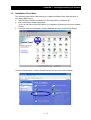
3- From the menu on the taskbar, choose [Settings] and then click [Control Panel ].
In case of Windows XP, choose [Control Panel] from the menu on the taskbar.
1-3
CHAPTER 1 Installing/Uninstalling the Software
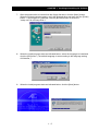
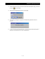
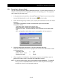
4-
Click the [Add/Remove Programs] icon to open the following window:
In case of Windows XP, click the [Add or Remove Programs] icon.
OS: In case of Windows 98
OS: In case of Windows NT
OS: In case of Windows XP
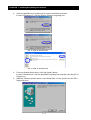
5-
6-
From the window shown above, click the [Install ] button.
In case of Windows XP, click the [Add New Programs] icon and then click the [CD or
Floppy] icon.
When the following window opens, insert Setup Disk 1 for the product into the PC's
floppy disk drive.
1-4
CHAPTER 1 Installing/Uninstalling the Software
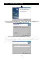
7-
After the product disk is inserted into the floppy disk drive, click the [Next ] button.
When the following window opens, verify the selected drive and then click the [Finish]
button. If a wrong drive is selected, click the [Browse] button to select the
"setup.exe" file on Setup Disk 1.
8-
When the install program starts as indicated below, select the language to install and
click the [OK] button. (The default language is set according to the language setting
of Windows.)
9-
When the install program starts as indicated below, click the [Next] button.
1-5
CHAPTER 1 Installing/Uninstalling the Software
10- Select an installation destination folder. To select a folder other than the default one, click
the [Browse] button to specify the installation destination folder.
After completion of folder selection, click the [Next ] button.
11- Select the product you want to install. For the standard software (AHF-P01), do nothing
but click the [Next ] button.
1-6
CHAPTER 1 Installing/Uninstalling the Software
12- The file copy process then starts.
13- When the files on the first product disk are completely copied, the following dialog
box opens. Insert Setup Disk 2 into the floppy disk drive and then click the [OK]
button to resume the file copy process. Repeat this procedure for the remaining
disks (Setup Disks 3,4 and 5).
NOTE) All the setup disks may not always be used for a reinstall.
14- When the file copy process entirely terminates, the following window opens. Click
the [Finish] button.
* The above window does not open if the employed OS is Windows NT.
1-7
CHAPTER 1 Installing/Uninstalling the Software
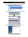
15- The system needs to be updated and restarted. When the following window opens,
close all the other open applications, choose "Yes, I want to restart my computer
now", remove the product disk from the floppy disk drive, and click the [Finish]
button to restart the system.
1.3
Uninstallation Procedure
You can uninstall the software by performing the following steps:
1-
From the menu on the taskbar, choose [Settings] and then click [Control Panel].
From the Add/Remove Programs window, choose the [Install/Uninstall] tab, and
then select "AHF" to uninstall it.
1-8
CHAPTER 1 Installing/Uninstalling the Software
In case of Windows XP, to remove AHF from your PC, choose [Control Panel] from
the menu on the taskbar, click the [Add or Remove Programs] icon, choose [AHF]
and then click the [Change or Remove Programs].
2-
The same program then starts as for installation and displays the following dialog box.
Click the [OK] button in the dialog box. The AHF uninstallation process then starts.
3-
When AHF is uninstalled, the following window opens. Click the [Finish] button to
conclude the uninstallation process.
1-9
CHAPTER 1 Installing/Uninstalling the Software
1.4
Upgrade Procedure
To upgrade the software, first uninstall the existing version of Setup Software AHF in a
manner explained earlier and then install the new version.
1 - 10
CHAPTER 2 Connecting to AD Series
Servo Drive
This section describes the cable for connecting the personal computer to the AD Series Servo
Drive and explains how to make the connection.
2. Connecting to AD Series Servo Drive
2.1 Connection Cable.................................................... 2-2
2.2 Connecting to the Servo Drive ................................ 2-2
2-1
CHAPTER 2 Connecting to AD Series Servo Drive
2. Connecting to AD Series Servo Drive
Q
Wiring precautions
CAUTION
1. When disconnecting or connecting the communication cable, be sure that the servo drive
and personal computer are both turned off. If you disconnect or connect the
communication cable while the power is on, the servo drive and personal computer may
become defective.
2. While the AC Servo Drive Setup Software is running, never disconnect or connect the
communication cable. When the communication cable is reconnected, be sure to exit the
software and restart. If you do not restart the software, the software and servo drive may
malfunction.
Q
Usage precautions
CAUTION
1. When the servo drive control power is turned off, be sure to exit the AC Servo Drive Setup
Software and restart. If you turn on the servo drive control power without exiting the
software, the software and servo drive may malfunction.
2. Do not turn off the servo drive control power while the initialization or parameter rewrite
process is in progress. If the servo drive control power turns off during a write, the
EEPROM data in the servo drive may become damaged, causing the servo drive to
improperly operate.
This section explains about the connection between the AD Series Servo Drive and PC.
2.1
Connection Cable
Create a cable that is wired as indicated below, or purchase the product suggested below:
Wiring diagram
8
Drive
8 GND
7 —
6 —
5 ER2
4 SD
3 RD
2 DR
1 RS
8-pin
1
8-pin modular connector
PC
1 DCD
2RxD
3TxD
4 DTR
5 GND
6 DSR
7 RTS
8 CTS
9 —
D-SUB 9-pin connector
The communication cable between the drive and PC
Model
ADCH-AT2
drive
Name
The communication cable
between the drive and PC
PC
8-pin modular connector D-SUB 9-pin connector
2.2
Connecting to the Servo Drive
With the above-mentioned cable, connect the servo drive to the personal computer.
Servo drive
: Connector marked "PC"
Personal computer
: RS-232C connector
2-2
CHAPTER 3 Operating Procedures
This section describes the procedures for launching and exiting the AC Servo Drive Setup
Software, exercising its monitoring, parameter setup, operation trace, and test run functions,
and changing the communication format.
3. Operating Procedures
3.1 Launching and Exiting............................................. 3-2
3.2 Monitoring Function................................................. 3-4
3.3 Parameter Setup Function ...................................... 3-6
3.4 Operation Trace Function ..................................... 3-17
3.5 Test Run and Adjustment Functions..................... 3-27
3.6 Changing the Communication Format .................. 3-45
3.7 Setting Motor parameters ..................................... 3-46
3-1
CHAPTER 3 Operating Procedures
3. Operating Procedures
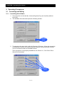
3.1
3.1.1
Launching and Exiting
Launching the software
12-
From the menu on the task bar, choose [Programs (P)], point to [Ahf], and then
click [Ahf].
The software then starts and opens the following window:
Connection
button
3-
To connect to the servo drive, click the [Connect (C)] button. When the connection
is established normally, the following window opens in several seconds, offering
you an increased number of selectable buttons.
If the connection is not properly established, see Section 4.1, If the Servo Drive
Cannot Be Connected.
Selectable
buttons
3-2
CHAPTER 3 Operating Procedures
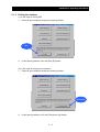
3.1.2
Exiting the software
(1) In the case of exiting AHF
1- Close all open windows except the opening window.
Exit
2-
In the opening window, click the [Exit (E)] button.
(2) In the case of exiting only connection
1- Close all open windows except the opening window.
Disconnect
2-
In the opening window, click the [Disconnect (X)] button.
3-3
CHAPTER 3 Operating Procedures
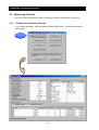
3.2
Monitoring Function
You can use the monitoring function to view the operation information in real time.
3.2.1
Starting the monitoring function
In the opening window, click the [Monitor Display(M)] button. The following window
then opens:
For starting
the monitoring
function
3-4
CHAPTER 3 Operating Procedures
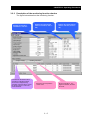
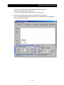
3.2.2
Description of the monitoring function window
The figure below describes the monitoring function:
Displays the operation
information in real time.
Furnishes the information about
operation by indicating that the
servo drive is stopped, being
operated, cannot be driven, cannot
be driven forward, or cannot be
driven backward.
Displays the input terminal
status in real time (0: OFF; 1:
ON).
Shows the current operation
control mode.
3-5
Displays the output terminal
status in real time (0: OFF; 1:
ON).
Shows a trip history. The
higher the number, the older
the event.
CHAPTER 3 Operating Procedures
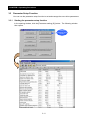
3.3
Parameter Setup Function
You can use the parameter setup function to set and manage the servo drive parameters.
3.3.1
Starting the parameter setup function
In the opening window, click the [Parameter setting (S)] button. The following window
then opens:
For starting the
parameter setup
function
3-6
CHAPTER 3 Operating Procedures
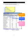
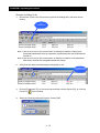
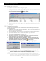
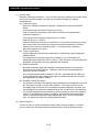
3.3.2
Description of the parameter setup window
The contents of the parameter setup window are shown below:
Open
Save As
Print
Read
Write
Default
You can assign a title.
(The title is displayed at
the time of printing.)
Parameter group setup tab
Specify the parameter
group you want to set up.
To apply parameter
changes, edit the data in
this column.
When you edit data, it
appears in red and
becomes suffixed with an
asterisk (*).
Parameter names
Parameter data
in servo drive
3-7
Parameter data in
personal computer
CHAPTER 3 Operating Procedures
3.3.3
Editing the parameters
Two examples are presented in this section to explain about the parameter editing
procedure.
• Choosing from a drop list --- Example 1) Editing FA-00
• Inputting value directly
--- Example 2) Editing Fb-00
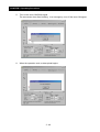
(Example 1) Editing FA-00
1- Choose the FA tab, click the mouse on the FA-00 setting field, and select a new
setting from the drop-down menu.
Note 1) (0) showed after S-P means the value used in the servo drive internally.
Note 2) An error occurs on the screen when an attempt is made to rewrite writeprotected parameters while an operation is performed with the SON terminal
turned on.
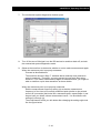
2-
Verify that the newly selected setting is displayed in red.
Changed value
becomes red and
symbol “*” is
attached to the right
side of the value.
3-8
CHAPTER 3 Operating Procedures
3-
Choose [Parameter (P)] on the menu bar and then choose [Write (W)], or click the
mouse on
on the toolbar.
4-
When the following dialog box opens, choose [OK].
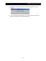
5-
The following message then appears to indicate that a parameter write is in
progress.
6-
In case of finishing rewriting parameters, red value becomes black and symbol “*”
attached to the right side of the value is disappeared.
3-9
CHAPTER 3 Operating Procedures
(Example 2) Editing Fb-00
1- Choose the Fb tab, click the mouse on the Fb-00 setting field, and enter a new
setting.
For
choosing Fb
Note 1) An error occurs on the screen when an attempt is made to rewrite writeprotected parameters while an operation is performed with the SON terminal
turned on.
Note 2) An error occurs on the screen when an attempt is made to write parameter
data that is outside the acceptable parameter range.
2-
Verify that the newly entered setting is displayed in red.
The edited setting
appears in red.
3-
Choose [Parameter (P)] on the menu bar and then choose [Write (W)], or click the
mouse on
4-
on the toolbar.
When the following dialog box opens, choose [OK].
3 - 10
CHAPTER 3 Operating Procedures
5-
The following message then appears to indicate that a parameter write is in
progress.
6-
In case of finishing rewriting parameters, red value becomes black and symbol “*”
attached to the right side of the value is disappeared.
3 - 11
CHAPTER 3 Operating Procedures
This parameter
can not be
changed.
NOTE 3: You cannot edit the parameters displayed in the parameter setup window if
the red "???" mark is displayed to the right of their settings.
NOTE 4: Do not turn off the servo drive control power while a parameter write is in
progress. If it turns off during a parameter write, the EEPROM data in the
servo drive may become damaged, causing the servo drive to improperly
operate.
3 - 12
CHAPTER 3 Operating Procedures
3.3.4
Saving the parameters
You can save the parameters in a file for parameter management purposes.
1- In the parameter setup window, choose [File (F)] on the menu bar and then choose
[Save As (S)], or click the mouse on
2-
on the toolbar.
When the Save As window opens, specify the file name and save destination.
You can save the file in either of the following two different formats:
CSV: Saves the file in a comma-separated value form.
TXT: Saves the file in a tab-separated value form.
(AHF cannot read the file saved in TXT form.)
NOTE: The data saved in this manner is not the servo drive data but the personal
computer data (data displayed in the current value column). If you save the
data without completing the write procedure, the saved data differs from the
data in the servo drive.
With this function, you can create different data files beforehand without writing data
into the servo drive.
3 - 13
CHAPTER 3 Operating Procedures
3.3.5
Loading the parameters
A file saved in a manner described in the preceding section can be used to set up the
parameters.
1-
In the parameter setup window, choose [File (F)] on the menu bar and then choose
[Open (O)], or click the mouse on
on the toolbar.
2-
When the Open window opens, specify the name of the file to load and its storage
location.
Note, however, that only CSV files can be loaded.
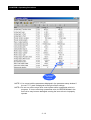
3-
After the parameters are loaded from the specified file, the parameter data is
displayed in red as shown below if its value for the personal computer differs from
its value for the servo drive.
Those values are
shown by red.
Write the data as needed into the servo drive.
3 - 14
CHAPTER 3 Operating Procedures
3.3.6
Reverting to factory default
You can revert to the factory default parameter settings. You can use this feature if, for
instance, the parameters are improperly set due to an operating error. This operation
can be done by pull-down menu.
1-
In the parameter setup window, choose [Parameter (P)] on the menu bar and then
on the toolbar.
choose [Initialization (I)], or click the mouse on
2-
When the following setup window opens, specify the initialization mode and default
data type.
The following initialization modes and default data types are selectable:
Initialization modes
Trip history clear: Clears the trip history only.
Data initialization: Clears the parameter data only.
Encoder zero clear: Clears the absolute value encoder's multi-rotation data
only.
(One- and smaller-rotation data must be managed by the host system.)
3-
Click the initialization start button to start the initialization process.
While the initialization process is in progress, the servo drive LED indicator reads
as indicated below:
Trip history clear
→
HC
Default data for Japan
→
JP
Encoder zero clear
→
AbSC
4-
After completion of initialization, the personal computer automatically reads the
data from the servo drive to conclude the initialization process.
NOTE: Do not turn off the servo drive control power during initialization. If it turns off
during a write, the EEPROM data in the servo drive may become damaged,
causing the servo drive to improperly operate.
3 - 15
CHAPTER 3 Operating Procedures
3.3.7
Printing the parameters
You can print out parameter data to compile a report.
1-
In the parameter setup window, choose [File (F)] on the menu bar and then choose
[Print (P)], or click the mouse on
2-
3.3.8
on the toolbar.
When the printer setup window opens, enter appropriate setup data to print out the
parameters.
Copying the parameters
You can copy the parameters from one servo drive unit to another by performing the
following procedure:
1- As directed earlier under "Saving the parameters", save in a file the parameters for
the servo drive at the copy source.
2- Exit Setup Software AHF and then turn off the personal computer and servo drive.
3- Connect the RS-232C cable to the servo drive at the copy destination.
4- Turn on the personal computer and servo drive.
5- Start Setup Software AHF. As directed earlier under "Loading the parameters",
load the parameters from the file to the personal computer.
6- As directed earlier under "Editing the parameters", verify that the changed data
settings are displayed in red, and choose [Parameter (P)] from the menu bar and
then choose [Write (W)], or click the mouse on
7-
on the toolbar.
When the parameters are properly written, the following messages appear.
NOTE1: Do not turn off the servo drive control power during a parameter write. If it
turns off during the parameter write, the EEPROM data in the servo drive may
become damaged, causing the servo drive to improperly operate.
NOTE2: An error occurs on the screen when an attempt is made to write parameter
data that is outside the acceptable parameter range or to rewrite write-protected
parameters while an operation is performed with the SON terminal turned on.
3 - 16
CHAPTER 3 Operating Procedures
3.4
Operation Trace Function
This function enables you to visually confirm the servo drive operation. The table below
shows the traceable items and control states.
Trace items
Resolution
(number of points)
Vertical
axis
512
65535
Data
update
intervals
Torque
Digital
Time
axis
Description
Speed
Analog graph 1
/graph 2
Trace item
Position
Trace type
Traceable
operation
control mode
Speed command
140µs
Traces the speed command from the
position controller or analog input or other
speed command.
1
4
x
Detected speed
value
Traces the detected speed value at all
times.
140µs
3
3
3
Output current
Traces the peak value of the current
supplied from the servo drive to the
servomotor.
4ms
1
1
1
Torque command
Traces the torque current command from
the speed controller or analog input or
other torque current command.
140µs
1
1
4
Output torque
Traces the torque current value.
140µs
2
2
Position command
high order
Traces the high-order portion of the
position controller's position command
(32768 dig = 1 rotation).
140µs
{
x
x
Position command
low order
Traces the low-order portion of the
position controller's position command
(32768 dig = 1 rotation).
140µs
{
x
x
Current position
high order
Traces the high-order portion of the
current position (32768 dig = 1 rotation).
140µs
2
2
2
Current position
low order
Traces the low-order portion of the
current position (32768 dig = 1 rotation).
140µs
2
2
2
Position error high
order
Traces the high-order portion of the
position controller's position error (32768
dig = 1 rotation).
140µs
1
x
x
Position error low
order
Traces the low-order portion of the
position controller's position error (32768
dig = 1 rotation).
140µs
1
x
x
Output voltage
Traces the execution value of the voltage 40ms
supplied from the servo drive to the
servomotor.
1
1
1
Traces all the input terminals.
Approx. 1
ms
{
{
{
Approx. 1
ms
{
{
{
2 points All input terminals
All output terminals Traces all the output terminals.
Traceable control states
{: Traceable at all times
1: Traceable (0 output at the time of a trip)
2: Traceable (undefined at the time of a trip)
3: Traceable (0 output when the encoder is abnormal)
4: Traceable (0 output at the time of a trip except for analog command input)
x: 0 output at all times
3 - 17
2
CHAPTER 3 Operating Procedures
3.4.1
Starting the operation trace function
The operation trace window opens when you click the [Trace operation (D)] button in
the opening window.
For starting the
operation trace
function
For starting the
operation trace
function
3 - 18
CHAPTER 3 Operating Procedures
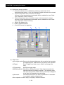
3.4.2
Description of the operation trace window
The figure below describes the contents of the operation trace window:
Open
Time display
based on t1axis cursor
Save As
Print
Start Operation Trace
Clear Graph
You can assign a title.
(The title is displayed
at the time of
printing.)
Display based on
t1-/t2-axis cursor
t: Time
difference
1/ t: Frequency
Time axis
display
Trace Setup
t1-axis cursor
When you hold
down the left mouse
button and drag the
mouse within the
drawing window, the
cursor appears.
Analog 1
display area
t2-axis cursor
When you rightclick the mouse in
the drawing
window, the cursor
appears.
Legend
Analog 2
display area
Trigger
point
Data value at t1-axis
cursor position
Time-Axis Scroll Bar
Change Y-Axis Scaling
When you remove
the check mark, the
graph disappears.
Data value
difference between
the t1- and t2-axis
cursor positions
Clear Window
Zoom Out One Step
Zoom In One Step
3 - 19
Digital
display area
CHAPTER 3 Operating Procedures
3.4.3
Operation trace sequence
1-
Open the operation trace window.
2-
Perform trace setup (see the next page for the setup procedure).
To do this, choose [Trace operation (T)] on the menu bar and then choose [Trace
setting (O)], or click
on the toolbar.
After completion of trace setup, click [OK].
3 - 20
CHAPTER 3 Operating Procedures
3-
Start an operation trace.
To do this, choose [Trace operation (T)] on the menu bar and then choose [Trace
Start (S)], or click
on the toolbar.
When an operation trace starts, the above message appears.
4-
When you click the trigger condition button or [Manual trigger] button in the above
dialog box, the servo drive transfers data to the personal computer and the
following dialog box opens.
NOTE1: Since the sampling cycle is short, the screen of “Trace operation was stopped!”
may not appear.
NOTE2: If you click the cancel button from the above dialog box, no graph will be drawn.
3 - 21
CHAPTER 3 Operating Procedures
5-
Upon completion of data transfer, the data appears as shown below.
3 - 22
CHAPTER 3 Operating Procedures
3.4.4
Operation trace setup
The trace setup window can be opened as directed below:
Choose [Trace operation (T)] on the menu bar and then choose [Trace setting (O)], or
click
on the toolbar.
After completion of setup, click [OK].
(1) Analog trace setup procedure
1- Check the channels to be validated (by entering a check mark in the
associated check boxes). Up to four channels of analog data can be traced.
2- From the drop-down menu, choose a trace target.
Refer to [3.4 Operation Trace Function] about the candidate for trace.
3- Select a display graph number (1 or 2) (No.1 is displayed in the area 1 and
No.2 is displayed in the area 2.).
4- Displayed color is selectable.
5- Label name is changeable by inputting directly.
6- Check the channel for triggering.
3-
1-
2-
3 - 23
4-
5-
6-
CHAPTER 3 Operating Procedures
(2) Digital trace setup procedure
1- Check the channels to be validated (by entering a check mark in the
associated check boxes). Up to four channels of digital contacts can be traced.
2- From the drop-down menu, choose a trace target.
(All input / output terminal data is selectable as the candidate for trace. Refer
to [3.4 Operation Trace Function].)
3- From the drop-down menu, choose the name of the terminal to be traced.
(All input / output terminal data is selectable as the candidate for trace. Refer
to [3.4 Operation Trace Function].)
4- Specify the display color.
5- Enter a graph label name.
6- Check the channel for triggering.
3-
1-
4-
5-
6-
2-
(a)
(d)
(b)
(c)
(e)
(3) Other setup
(a)Pre-trigger points:Data can be displayed beginning with a position that precedes
the triggering point. Make this entry to specify such a position.
(b)Trigger:
Enter a trigger level (this entry is valid for an analog trace
only).
(c)Trigger edge:
Specify the trigger edge.
(d)Sampling period: Specify the sampling intervals. Data will be sampled at the
specified intervals for display purposes. The maximum trace
time (time during which a trace can be performed) is displayed
to the right of the sampling interval setting.
(e)Automatic:
Check this option when you want to optimize the Y-axis scale
in accordance with the sampled data.
After completion of entire setup, click [OK] to close the window.
3 - 24
CHAPTER 3 Operating Procedures
3.4.5
Graph display setup
(1) X-axis setup procedure
With the toolbar near a graph axis, you can enlarge the X-axis or revert to the
standard size of each graph axis. Use the following toolbar buttons.
X-axis one-step
enlargement
X-axis one-step
reduction
(2) Y-axis setup procedure
With the toolbar near a graph axis, you can change the Y-axis scale.
To change the Y-axis scale, click the following toolbar button.
Y-axis scaling change
The following window then opens. In the open window, enter scaling values and
then click the [OK] button. The graph is then redrawn in accordance with the
specified scaling values.
3 - 25
CHAPTER 3 Operating Procedures
(3) Hiding a graphed line
You can hide a graphed line by removing the associated check mark as indicated
below. To redisplay the graphed line, put a check mark back in the check box.
For hiding or displaying a
graphed line
(4) Clearing the contents of the window
You can erase the on-screen graph by choosing [Trace operation (T)] on the menu
bar and then choosing [Clear display (C)], or click
on the toolbar.
You can also use the following toolbar buttons to erase the entire contents of the
window or individual graphs.
Erasing all graph axes
Erasing a specific graph axis
3 - 26
CHAPTER 3 Operating Procedures
3.5
Test Run and Adjustment Functions
This section describes the functions that are useful for a test run.
3.5.1
Jogging and homing
With the personal computer, you can start a jog operation or return the servomotor to its
home for test run purposes.
<Jog operation>
The jog operation function can be exercised to check the servo drive, servomotor,
power supply, or other wiring. (For the use of the jog operation function, no external I/O
wiring connection is necessary.)
(1) Jog operation procedures
Two different jog operations are available: normal jogging and pulse train based
jogging. Normal jogging is conducted in the speed control mode, whereas pulse
train based jogging is conducted in the position control mode with a preselected
number of pulses fed. Both of these jog operations are described below.
(1-A) Jog operation procedure
This operation is performed according to a given speed command until the stop
command is received.
NOTE 1: While this operation is being conducted, do not enter a signal from the SON
terminal or other I/O connector. If such a signal enters, the operation is
performed in compliance with it.
NOTE 2: This jog operation is performed at an acceleration/deceleration time setting of 0
s and in accordance with the currently selected control gain, speed limiter, and
other settings.
The procedure is described below:
1- In the opening window, click the [Test run and Adjustment (T)] button.
When the following window opens, click the Jog & homing tab.
For entering the
test run and
adjustment mode
NOTE 3: If the monitor display window is open, close it beforehand.
3 - 27
CHAPTER 3 Operating Procedures
23-
Enter the speed command for jogging in field 2 below.
Conform the safety and then click a button to specify the desired direction of
operation (see 3) in the figure below). (The servomotor then starts rotating in the
specified direction.)
NOTE: Since this step causes the servomotor to run, confirm the safety beforehand.
Upon completion of the above step, the contents of the window change as
indicated below.
2-
3-
4-
When you click the [Stop] button, the servomotor stops (servo OFF) (see 4) in the
figure below).
4-
3 - 28
CHAPTER 3 Operating Procedures
(1-B) Pulse feed jog operation procedure
In compliance with a given position command, the pulse feed jogging operation is
performed in the position control mode until the specified position is reached.
NOTE 1: While this operation is being conducted, do not enter a signal from the SON
terminal or other I/O connector. If such a signal enters, the operation is
performed in compliance with it.
NOTE 2: This jog operation is performed at an acceleration/deceleration time setting of
0 s and in accordance with the currently selected control gain, speed limiter,
and other settings.
The procedure is described below:
1- From the following window, enter the number of feed pulses (note that one rotation
is equivalent to 32768 pulses).
1-
2-
23-
Enter a speed limit value (Fb-20/Fb-21) that is not higher than 300 min-1. (Observe
the limit to prevent the servomotor from tripping or getting out of control.)
Confirm the safety and then click the [Forward] or [Reverse] button (see 2) in the
above figure). (The servomotor then rotates in the specified direction and becomes
positioned according to the command value.)
NOTE: Since this step causes the servomotor to run, confirm the safety beforehand.
3 - 29
CHAPTER 3 Operating Procedures
While positioning is in progress after completion of the above step, the window
looks like the figure below:
3-
To abort the positioning process (servo OFF), click the [Stop] button, which is
numbered 3- in the above figure.
4-
Upon completion of positioning, you are returned to the initial window.
In the resulting state, the servo ON state continues. Therefore, click the [Stop]
button, which is numbered 3- in the above figure.
<Homing>
With this homing function, you can return the servomotor to its home from the personal
computer.
(For the use of this homing function, only the ORL terminal connection is required.)
The procedure is described below:
1- Specify the direction of homing.
2- Select a homing mode.
3- Enter a homing speed.
4- Enter an acceleration time and deceleration time.
5- Click the [Homing start] button.
Since this starts a homing operation (rotates the servomotor), confirm the safety before
clicking the button.
6- To abort the homing operation, click the [Stop] button.
12345-
6-
NOTE: For the details of the homing function, refer to the instruction manual of the AC
servo drive AD Series.
3 - 30
CHAPTER 3 Operating Procedures
3.5.2
Off-line tuning
The total inertia, including the motor inertia, can be approximately calculated in the offline state.
To exercise this function, perform either of the following procedures.
(1) Procedure for fully-automatic off-line tuning
1-
In the opening window, click the [Test Run and Adjustment (T)] button. The
following window then opens (click the Offline tuning tab).
For starting
the test run and
adjustment
functions
Offline tuning
3 - 31
CHAPTER 3 Operating Procedures
(A)
(B)
(C)
(D)
2-
Enter the following parameters which are required for tuning:
(A) Speed control cut-off frequency
Set the speed control cut-off frequency for off-line tuning. Enter a setting at
which no hunting occurs.
(B) Tuning inertia initial value
Set the inertia for the beginning of off-line tuning. When an approximate inertia
value is known, make this entry to ensure that tuning is rapidly completed. If
the approximate inertia value is not known, you do not have to make this entry.
If you do not make this entry, the off-line tuning function estimates the inertia.
(C) Tuning rotating speed
Enter the rotating speed for off-line tuning. If you are sure that the initial value
does not damage the machine connected to the servomotor, you can use the
initial setting.
(D) Acceleration/deceleration time
Set the pattern operation acceleration/deceleration time for off-line tuning. If
you are sure that the initial value does not damage the machine connected to
the servomotor, you can use the initial setting.
34-
Click the [Continuous pattern tuning start] button.
Confirm the safety, and then turn on the FOT terminal, ROT terminal, and SON
terminal in order named. A pattern operation is then continuously performed to
estimate the inertia.
3 - 32
CHAPTER 3 Operating Procedures
5-
After completion of inertia estimation, the operating waveform for the last pattern
operation is downloaded from the servo drive to display the estimation result as
indicated below:
6-
After completion of tuning, be sure to finish the Auto-tuning mode by tuning SON
terminal off, RS terminal on and RS terminal off.
NOTE 1: Exercising this function automatically rewrites inertia setting Fd-00.
NOTE 2: Even when the tuning process is aborted, be sure to finish the Auto-tuning
mode by turning SON terminal off, RS terminal on and RS terminal off.
3 - 33
CHAPTER 3 Operating Procedures
(2) Procedure for performing an off-line tuning process while verifying individual
steps
12-
In the opening window, click the [Test Run and Adjustment (T)] button. The
following window then opens (click the Offline tuning tab).
Enter the following parameters which are required for tuning:
(A) Speed control cut-off frequency
Set the speed control cut-off frequency for off-line tuning. Enter a setting at
which no hunting occurs.
(B) Tuning inertia initial value
Set the inertia for the beginning of off-line tuning. When an approximate inertia
value is known, make this entry to ensure that tuning is rapidly completed. If
the approximate inertia value is not known, you do not have to make this entry.
If you do not make this entry, the off-line tuning function estimates the inertia.
(C) Tuning rotating speed
Enter the rotating speed for off-line tuning. If you are sure that the initial value
does not damage the machine connected to the servomotor, you can use the
initial setting.
(D) Acceleration/deceleration time
Set the pattern operation acceleration/deceleration time for off-line tuning. If
you are sure that the initial value does not damage the machine connected to
the servomotor, you can use the initial setting.
(A)
(B)
(C)
(D)
34-
Click the [1 pattern tuning start] button.
Confirm the safety, and then turn on the FOT terminal, ROT terminal, and SON
terminal in order named. A one-pattern operation is then performed to estimate the
inertia.
3 - 34
CHAPTER 3 Operating Procedures
5-
After completion of inertia estimation, the operating waveform for the last pattern
operation is downloaded from the servo drive to display the estimation result as
indicated below:
6-
Check whether the waveform is adequate. If necessary, you can click the [1
pattern tuning start] button again. A one-pattern operation is then performed to
estimate the inertia. You can continue to perform tuning in this manner while
checking the on-screen waveform each time.
After completion of tuning, be sure to finish the Auto-tuning mode by turning SON
terminal off, RS terminal on and RS terminal off.
7-
NOTE 1: Exercising this function automatically rewrites inertia setting Fd-00.
NOTE 2: Even when the tuning process is aborted, be sure to finish the Auto-tuning
mode by turning SON terminal off, RS terminal on and RS terminal off.
3 - 35
CHAPTER 3 Operating Procedures
3.5.3
Mechanical system diagnostic measurement procedure
The resonance point of the machine connected to the servomotor can be measured.
The procedure is described below.
NOTE: This function is for servo drive AD2 only. It does not properly work for models
earlier than AD2.
1-
Make preparations as directed below:
Before making measurements, exercise the parameter setup function to set the
parameters as shown in the following table:
Parameter name
2-
No.
Setting
Initial value
Moment of inertia
Fd-00
Enter an approximate value.
Motor-specific value
Speed control cut-off frequency
Fd-01
5 to 10Hz
30Hz
Torque command filter time constant
Fd-06
0ms
2ms
Notch filter bandwidth 1
Fd-13
0dB
0dB
Notch filter bandwidth 2
Fd-15
0dB
0dB
In the opening window, click the [Test Run and Adjustment (T)] button. The
following window then opens. Click the Machine Diagnosis tab.
This function is for servo drive AD2 only. It does not properly work for models
earlier than AD2.
3 - 36
CHAPTER 3 Operating Procedures
For AD1, click [OK] and close the Machine Diagnosis window.
(AD1 series is showed as “AD series”.)
For AD2, click [OK] and proceed to perform the next step.
3-
Perform mechanical system diagnostic setup as directed below:
From the Mechanical Diagnostics window, enter mechanical system diagnostic
settings as explained below:
(a)
(b)
(c)
(d)
3 - 37
CHAPTER 3 Operating Procedures
(1) Overall setup
Read the following instructions. If you are sure that your machine will remain intact
and create no safety hazard, you can use the default settings for making
measurements.
(a) Frequency range
Define the machine resonance frequency measurement range as directed
below:
If an approximate resonance frequency is known:
Enter a frequency range that covers about fives times the approximate
resonance frequency.
If an approximate resonance frequency is not known:
Select a range of "- 900 Hz".
After the resonance frequency is measured, you should set a frequency range
that covers about fives times the measured resonance frequency, and then
measure the resonance frequency again. It would produce a relatively
accurate measurement result.
(b) Torque (command )
Set the diagnostic signal torque amplitude for mechanical system diagnostic
measurements.
For measurement accuracy assurance purposes, you should select an
adequately high amplitude (100% or lower). Note, however, that the higher the
amplitude, the greater the torque applied to the machine.
(c) Speed (command)
Mechanical system diagnostic checkout is performed while an operation is
conducted at a constant speed. Therefore, specify the constant speed by
entering a speed command.
The entered speed should be between 100 min-1 and rated speed (3000 min-1
for the standard product), adequately high but not detrimental to the machine,
and appropriate for stable rotation.
(d) Allowable (operation range)
The distance moved for mechanical system diagnostics is displayed in terms of
the equivalent number of servomotor rotations. The machine comes to an
immediate stop at the end of the mechanical system diagnostic checkout, but
moves slightly more than the displayed value due to the inertia of the machine.
You should reposition the servomotor so that the machine can move slightly in
excess of the displayed number of rotations, decrease the speed command
value, or reduce the operation range adjustment value, which is adjustable
from the advanced setup by clicking [Options] button.
(2) Advanced setup
You do not have to perform advanced setup under normal conditions. However,
you can enter any necessary advanced setup data by clicking [Options] button.
3 - 38
CHAPTER 3 Operating Procedures
(e) Number (of data)
You can specify the number of FFT computation points for mechanical system
diagnostics. The larger the number of points, the higher the measurement
accuracy. However, the time required for a data upload will increase with an
increase in the number of points. You can use a relatively low setting for
making initial rough measurements and raise the setting for final detailed
measurements to reduce the required measurement time. In principle,
measurements should be at a maximum setting of 4096 points.
(f) Window (function)
A window function can be exercised for the data. If a measured waveform is
messy, it may become clean when you change the window function option.
You should basically use the "Hunning" setting for measurement purposes.
(g) Operation (range adjustment)
When you decrease the setting, the operation range for measurement
decreases, but the waveform of a low-frequency region becomes messy. If the
waveform of a low-frequency region is disordered at a default setting, you
should increase the setting.
4-
Start the diagnostic checkout by clicking the [Start] button.
Click
3 - 39
CHAPTER 3 Operating Procedures
5-
Turn on the servo ON(SON) signal.
The servomotor then starts rotating. In an emergency, turn off the servo ON signal.
6-
When the operation ends, a data upload begins.
3 - 40
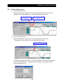
CHAPTER 3 Operating Procedures
7-
The mechanical system diagnostics window opens.
8-
Turn off the servo ON signal, turn the RS terminal on and then back off, and exit
the mechanical system diagnostics mode.
9-
Observe the waveform to determine whether or not to make measurements again.
When the resonance point is properly measured:
Proceed as directed below.
The waveform shown in Step 7- indicates that a relatively clear resonance
point is measured. Therefore, you may proceed to next notch filter setup.
However, if you make measurements again as indicated below, you might be
able to measure a quite clear waveform as shown below.
When the resonance point is not properly measured:
Edit the measurement frequency setting (a) so that the measurement
frequency is five times of a currently measured peak (similar to the pointed
summit of a mountain) that looks like a resonance point, repeat Steps 4- and
beyond until you obtain a clean measurement result. You should also edit
settings (b) through (g).
The measurement result you will obtain after changing the setting might look
like the figure below:
3 - 41
CHAPTER 3 Operating Procedures
NOTE: You might not be able to obtain a clean measurement result shown above
depending on your machine no matter how many times you edit the settings.
However, there is no practical problem as far as the resonance point (a peak
similar to the pointed summit of a mountain) is measured.
3 - 42
CHAPTER 3 Operating Procedures
3.5.4
Notch filter setup procedure
The notch filter parameter can be set by performing the procedure described below (it is
necessary to measure the resonance point as directed in the preceding section):
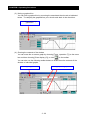
1- As shown below, left-click the mouse on a resonance point (a peak similar to the
pointed summit of a mountain) within the waveform display area of the mechanical
diagnostics window. If any fine adjustments are needed, use the cursor buttons on
the left-hand side until the mouse cursor is positioned at the peak.
Left-click the
mouse.
Click these for
fine adjustments.
2-
Right-click the mouse at the intersection of a perpendicular line drawn from the
peak and the waveform line sloped downward to the right.
Line sloped downward to
the right (not displayed in
the window)
(The black rectangular Q
is displayed.)
Parallel
3 - 43
CHAPTER 3 Operating Procedures
3-
Click the [Filter 1] button. The recommended settings are then displayed in the
boxes to the right of the clicked button.
4-
You can set up to two resonance frequencies. If there is another resonance point,
repeat Steps 1- and beyond and set it with the [Filter 2] button.
NOTE: If resonance points are close to each other, the servomotor operation may
become unstable even when you properly complete filter setup. In such an
instance, set a predominant resonance point.
5-
Click the [Writing] button. The settings are then transferred to the servo drive.
6-
Restore the gain and other settings to their previous values, and then start an
operation to check whether the degree of vibration is decreased. If the degree of
vibration is not significantly decreased, slightly change the frequency setting (Fd12/Fd-14) to locate a point at which the degree of vibration decreases. It is also
well to remember that the notch filter function may effectively work when you adjust
the bandwidth (Fd-13/Fd-15).
NOTE: Mechanical diagnostic measurements are to be used as a guide only. The
measured resonance frequency may slightly deviate from what is correct.
3 - 44
CHAPTER 3 Operating Procedures
3.6
Changing the Communication Format
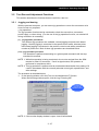
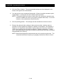
1-
In the opening window, click the [Communication format (F)] button.
Communication
Format
2-
When the following window opens, make necessary changes:
3-
After necessary changes are made, click either of the following buttons depending on
the situation:
When the connection is established: [Setting] button --- Changes the settings for both
the servo drive and personal computer and establishes the connection again.
When the connection is not established: [Close] button --- Changes the settings for
the personal computer only.
3 - 45
CHAPTER 3 Operating Procedures
3.7
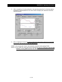
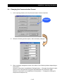
1-
Setting Motor parameters
In the opening window, click the [Motor constants setting (I)] button. When the
following window opens, set up motor constants according to the following points.
Motor
constants
2-
Select the motor type from the pull-down button. Note that unmatched motor
constants against the amplifier you use can not be set in the amplifier.
Select the
motor type
3 - 46
CHAPTER 3 Operating Procedures
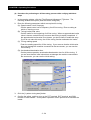
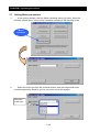
3-
Click the [Write Motor constants] button.
It normally performs in order of “Check the output rating”, “Write Motor constants” and
“Check Motor constants”. Which operation is performed is selectable by the check-box.
Click this
button to start
operation.
4-
When the setting is finished correctly, the following message is showed. After that
[Servo amplifier initialization] button is valid.
Servo amplifier
initialization
3 - 47
CHAPTER 3 Operating Procedures
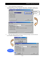
5-
Click the [Servo amplifier initialization] button. As the following message is showed,
click one of buttons
[OK] button : starts to initialize parameters in the servo amplifier.
[Cancel] button : cancels the initialization of parameters in the servo amplifier.
6-
During the initialization, the following screens are displayed in order according to the
status of process.
7-
When the initialization is finished, the following message is showed. Before operation,
be sure to power off and power on the control power circuit.
8-
Click the [Close] button to finish the motor constants setting
Close
3 - 48
CHAPTER 3 Operating Procedures
In case that unmatched motor constants against the amplifier is selected :
the error occurs at the step of “Check the output rating”. And then the following message
is showed.
Be sure to check the voltage class and output rating of amplifier and motor, and then
select the correct motor constants.
3 - 49
CHAPTER 3 Operating Procedures
MEMO
3 - 50
CHAPTER 4 Troubleshooting Guide
This section furnishes the instructions for troubleshooting the product when it malfunctions or
erratically operates.
4. Troubleshooting Guide
4.1 If the Servo Drive Cannot Be Connected ................4-2
4.2 If Parameters Cannot Be Written ............................4-2
4.3 If Parameters Cannot Be Read...............................4-2
4.4 If Parameter Initialization Does Not Work ...............4-3
4.5 If the Operation Trace Function
Does Not Properly Work .........................................4-3
4-1
CHAPTER 4 Troubleshooting Guide
4. Troubleshooting Guide
4.1
If the Servo Drive Cannot Be Connected
If the servo drive cannot be connected, proceed as directed below.
Probable cause
4.2
Remedy
A wrong connector is used for connecting the servo
drive to the personal computer.
Check the connector and use a correct connector.
The connection cable is improperly connected or in
poor contact.
Check to ensure that the cable is properly
connected and in proper contact.
The servo drive differs from the personal computer in
baud rate or other communication setting.
Check the baud rate and other communication
settings. Correct the personal computer or servo
drive settings as needed.
The RS-232C port (COM) is improperly set.
(Personal computer setting check --- Choose [Start],
[Settings], [Control Panel], [System], [Device
Manager] and then check the COM port setting.)
Note the personal computer's COM port setting for
AHF, and then adjust AHF's "Communication
Format" setting until it agrees with the personal
computer's setting.
If Parameters Cannot Be Written
If the above message appears, proceed as directed below because it is conceivable that
the problem cause is as indicated below:
Probable cause
4.3
Remedy
An attempt was made to rewrite a write-protected
parameter while an operation was performed with the
SON terminal turned on.
Turn off the SON terminal and write a parameter.
An attempt was made to write parameter data that
was outside the acceptable parameter range.
Write data that is within the acceptable parameter
range.
An attempt was made to write data while the servo
drive was tripped.
Reset the trip with the RS terminal and then write
data.
If Parameters Cannot Be Read
If the parameters can not be read from the servo drive, proceed as directed below
because it is conceivable that the problem cause is as indicated below:
Probable cause
Remedy
An attempt was made to read data while the
communication cable between servo drive and PC
was break or the connector of the cable is not
connected to PC and the servo drive firmly.
4-2
Check the communication cable and connect it to
PC and the servo drive again.
CHAPTER 4 Troubleshooting Guide
4.4
If Parameter Initialization Does Not Work
If the parameter initialization does not be work, proceed as directed below:
Probable cause
Remedy
Parameters can not be read from the servo drive after
initialization.
Confirm that the indication of the initialization is
displayed on the digital operator built in the servo
drive.
Initialize the parameters again.
An attempt was made to initialize data while the
communication cable between servo drive and PC
was break or the connector of the cable is not
connected to PC and the servo drive firmly.
4.5
Check the communication cable and connect it to
PC and the servo drive again.
If the Operation Trace Function Does Not Properly Work
If the operation trace function does not properly work, proceed as directed below.
Probable cause
Remedy
Triggering was not achieved because improper
trigger conditions were set.
Correct the trigger conditions.
4-3
CHAPTER 4 Troubleshooting Guide
MEMO
4-4
CHAPTER 5 Appendixes
5. Appendixes
5.1 Files to Be Copied to System..................................5-2
5.2 Connection to a Personal Computer
without a Serial Port (RS-232C)..............................5-3
5-1
CHAPTER 5 Appendixes
5. Appendixes
5.1
Files to Be Copied to System
The table below lists the names of the files that are copied to the c:\windows\system
directory when you install the software (it is presumed that Windows is installed on drive
C.):
OCX files
COMDLG32.OCX
MSCOMCT2.OCX
MSCOMCTL.OCX
TABCTL32.OCX
PDQCOM32.OCX
MSFLXGRD.OCX
VSVIEW3.OCX
VSFLEX6D.OCX
ACSGRAPH.OCX
DLL files
MSVBVM60.DLL
OLEAUT32.DLL
ASYCFILT.DLL
CMDLGJP.DLL
COMCAT.DLL
MSCC2JP.DLL
MSCMCJP.DLL
OLEPRO32.DLL
TABCTJP.DLL
VB6JP.DLL
STRFMT.DLL
FLXGDJP.DLL
MSVCRT.DLL
VB6STKIT.DLL
MFC42.DLL
5-2
CHAPTER 5 Appendixes
5.2
Connection to a Personal Computer without a Serial Port (RS-232C)
When using the AC Servo Drive Setup Software on a personal computer without an RS232C port to establish a connection to the AD Series, it is suggested that you use the
following PC card. If you use the following PC card, you do so at your own risk.
< PC Card >
Product name
PC Card Standard TypeII RS-232C PC Card
Manufacturer
RATOC Systems
Type
REX-5056V
Standard price
¥19,800
Accessory
9-pin D-sub (male) cable (50 cm)
< USB Serial Converter >
Product name
USB Serial Converter
Manufacturer
RATOC Systems
Type
REX-USB60
Standard price
¥5,980
Connector
USB (type A)
OS
Windows XP, Windows 2000, Windows Me,
Windows 98 Second Edition
For details, visit the following:
http://www.rexpccard.co.jp/
Note, however, that no operational checkout has been completed to investigate the
influence of the use of various installation sites (field use, etc.), different types of personal
computers, and various other different operating conditions.
Therefore, it is well to remember that your use of the above PC card is at your own risk.
5-3
CHAPTER 5 Appendixes
5.2.1
Connection procedures and precautions
(1) Installing the PC card
Install the PC card as directed in its documentation. Note what COM port the PC
card RS-232C is assigned to in the installation process.
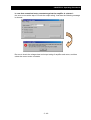
(2) Connecting Setup Software AHF
When you install and launch Setup Software AHF, COM1 is set up as the
communication port. Therefore, change the assigned COM port to the abovementioned COM port the PC card RS-232C and establish the connection by
performing the following procedure (which presumes that the PC card RS-232C is
assigned to COM2):
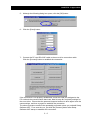
1- Launch Setup Software AHF.
2- Click the [Communication format] button.
3- Set the communication port to COM2.
4-
Click the [Setting] button.
5-4
CHAPTER 5 Appendixes
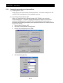
5-
Although the following dialog box opens, click the [OK] button.
6-
Click the [Close] button.
7-
Connect the PC card RS-232C cable to the servo drive connection cable.
Click the [Connect] button to establish the connection.
If the connection is not properly established, check the COM port assigned to the
PC card and the communication baud rate, data bit, stop bit, and parity settings for
the servo drive. Ensure that the personal computer and servo drive agree have the
same settings, and then try again to establish the connection.
The above procedure need not be repeatedly performed unless you uninstall Setup
Software AHF. From next time on, just click the [Connect] button after Setup
Software AHF startup to establish the connection.
5-5
CHAPTER 5 Appendixes
MEMO
5-6