1
C H A P T E R
3
Channelized T3 Trunk Card
The Cisco AS5800 universal access server supports a channelized T3 (CT3) ingress interface that
provides asynchronous aggregation of channelized interfaces and multiplexing on a single T3 facility.
The CT3 trunk card is installed in the Cisco 5814 dial shelf chassis in slots 0 to slot 5. The
Cisco AS5800 currently supports as many as two CT3 trunk cards.
This chapter explains how to remove and replace a CT3 trunk card in the Cisco 5814 dial shelf chassis,
and also includes steps for verifying and troubleshooting your trunk card installation and configuring
your software.
CT3 Trunk Card Overview
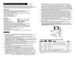
The CT3 trunk card contains an onboard M13 multiplexer, which multiplexes 28 separate T1 lines into
a single T3 line. Each CT3 trunk card installed in the Cisco 5814 dial shelf contains all necessary
functionality to terminate link signaling and incoming digital calls.
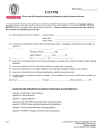
Figure 3-1 shows the CT3 trunk card.
Cisco AS5800 Universal Access Server Dial Shelf Card Guide
78-7097-03
3-1
Chapter 3
Channelized T3 Trunk Card
CT3 Trunk Card Overview
CT3 Trunk Card
FC
PU
FC
PU
PW
R
M
AIN
T
PW
R
M
AI
NT
Figure 3-1
HCPU
R
OO ALM
P
S
F
AI
OO
T
RF LOS 3EN
FE
FE
OO
F
AIS
T
RF LOS 3EN
T3
LO
OP
T3
LO
OP
NL
LA
LM
M
ON
IT
OR
#
NL RA
OO LM
P
LA
LM
M
ON
IT
OR
#
HCPU
RC
VR
Receive BNC connector
UT
(O
TX
)
(IN
CHANNELIZED T3
12125
RX
Transmit DSx1 connector
Receive DSx1 connector
)
XM
TR
Transmit BNC connector
Each CT3 trunk card performs the following functions:
•
Provides physical termination for as many as 672 sessions.
•
Provides digital termination for as many as 256 DS0 connections (calls) using onboard High-Level
Data Link Control (HDLC) controllers. Note that the D-channel of a PRI consumes a single channel
of an HDLC controller.
•
Removes framing and embedded signaling bits (or inserts them, depending on the direction of the
flow), demultiplexing the calls. The framer CPU sends the data stream to onboard time-division
multiplexing (TDM) resources, which break out each call and pass each call to an appropriate call
termination resource. Digital or ISDN-originated calls are terminated onboard the CT3 trunk card
on HDLC controllers.
Note
Each D-channel consumes an HDLC controller.
Analog modem-originated calls are passed over the dial shelf backplane TDM bus to an available
modem resource. The system software controls modem and HDLC resource management.
•
Responds to time-sensitive signaling. Each CT3 trunk card can supply two clocks from any two of
its 28 ports. You can assign priorities to these clocks or accept the default values assigned by the
software.
Cisco AS5800 Universal Access Server Dial Shelf Card Guide
3-2
78-7097-03
Chapter 3
Channelized T3 Trunk Card
CT3 Trunk Card Overview
•
Processes counting information for performance monitoring.
•
Supports online insertion and removal (OIR), a feature that allows you to remove and replace a trunk
card in the Cisco 5814 dial shelf while the system is operating without disrupting other cards and
their associated calls. If you remove a trunk card while the system is operating, all calls associated
with the CT3 lines on that card are dropped. Calls being handled by other trunk or modem cards,
however, are not affected. For more information, see the “Online Insertion and Removal” section on
page 1-1.
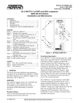
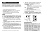
Figure 3-2 shows two trunk cards installed in a fully-configured Cisco 5814 dial shelf chassis.
Figure 3-2
Cisco 5814 Dial Shelf Chassis Fully Configured with Trunk Cards Installed
POWER
LED
FAULT
Captive LED
Captive
screw
Blower assembly
screw
POWER
FAIL
T
T
MA
R
MO
MO
DE
DE
MS
MS
PW
IN
T
T
IN
MA
R
IN
R
PW
PW
MA
MS
MS
MO
MO
DE
DE
DE
MO
MO
T
T
R
IN
PW
MS
MA
R
IN
MA
R
DE
DE
MS
MS
MS
DE
MO
MO
MS
MS
DE
DE
MO
MO
PW
MA
PW
IN
T
T
T
R
IN
R
IN
PW
MA
PW
MA
IN
R
IN
MA
MA
PW
R
PW
FC
FC
PU
PU
T
CALLS
J
NL RA
OO LM
P
LM
LA
FF
FF
TO
TO
CU
M
ONI
TO
R
ST
ST
HI
HI
CU
NL RA
OO LM
P
N
O
O
AC
N
AC
MI
MI
#
CALLS
#
CALLS
MA
CALLS
J
M
ONI
TO
R
CALLS
MA
LM
CALLS
US
MB
R
PW
CALLS
US
MB
R
PW
CALLS
HCPU
CALLS
HCPU
CALLS
HCPU
HCPU
HCPU
HCPU
HCPU
HCPU
HCPU
HCPU
HCPU
HCPU
LA
SERIES
PW
R
M
AI
NT
PW
R
M
AI
NT
Cisco AS5800
ALARM
ALARM
R
R
EA
EA
CL
CL
ALARM
ALARM
T
SE
SE
T
DISP
DISP
N
N
TE
TE
AT
AT
DISP
DISP
K
K
CL
CL
ST
0
OT
SL
ST
MA
MA
OT
SL
0
1
OT
OT
SL
SL
1
PCMCIA
PCMCIA
T3
LO
OP
OO AIS
F
FE
T3
RF LOS EN
TR
XM
XM
TR
RC
VR
10 BASE T
T3
LO
OP
ALARMS
10 BASE T
OO AIS
F
NETWORK CLOCK
ALARMS
FE
T3
RF LOS EN
CONSOLE
NETWORK CLOCK
VR
CONSOLE
RC
DIAL SHELF CONTROLLER
DIAL SHELF CONTROLLER
)
UT
)
UT
(O
(O
TX
TX
)
(IN
)
(IN
RX
DIAL SHELF INTERCONNECT
RX
DSI
DSI
DIAL SHELF INTERCONNECT
12266
MODEM
MODEM
MODEM
MODEM
MODEM
MODEM
MODEM
MODEM
MODEM
MODEM
CHANNELIZED E1/T1
CHANNELIZED E1/T1
Trunk cards
Modem cards
Dial shelf
controller cards
Cisco AS5800 Universal Access Server Dial Shelf Card Guide
78-7097-03
3-3
Chapter 3
Channelized T3 Trunk Card
CT3 Trunk Card Overview
Clocking
All Cisco AS5800 access server trunk cards use the same transmit clock. This clock can originate from
the following sources:
•
TDM clock source—A priority value from 1 to 50 that is applied to a clock source when multiple
clock sources are used
•
External clock source—A clock source external to the access server
Clocks are prioritized by slot number (slots 0 to 5). The highest-priority clock is selected from the card
in slot 0 and used as the default clock. If this clock fails, the highest-priority clock from the card in slot 1
becomes the default clock, and so forth.
The trunk card then forwards the clocks to the dial shelf controller. The dial shelf controller selects the
highest-priority clock as the system primary clock, and the rest of the clocks remain in a prioritized
backup queue.
Instead of using the default algorithm for clock selection, you can specify clocks through global
configuration and select a maximum of two clocks per trunk card.
If you configure fewer than two clocks on a trunk card and all other configured clocks fail, clock
selection resorts to the default algorithm on that card and the second clock will be selected automatically.
CT3 Clocking
CT3 trunk cards are usually attached to an external device, such as a Digital Access and Crossconnect
System (DACS) or Add-Drop Multiplexer (ADM). This point-to-point link requires a single clock source
to which the CT3 link is timed. You must determine whether you want the CT3 trunk card or an external
device to be used as the primary clock source and configure it accordingly during the software
configuration process, which is discussed in the “Configuration Commands” section on page 3-12.
CT1 Clocking
The CT3 trunk card has 28 T1 framers that always get their clock from the line. As a result, configuration
of T1 clock sources is not allowed.
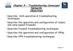
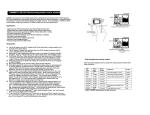
LED and Alphanumeric Indicators
The CT3 trunk card front panel is designed with LED and alphanumeric displays to provide trunk card
status. (See Figure 3-3.)
Cisco AS5800 Universal Access Server Dial Shelf Card Guide
3-4
78-7097-03
Chapter 3
Channelized T3 Trunk Card
CT3 Trunk Card Overview
CT3 Trunk Card Front Panel LED and Alphanumeric Indicators
FC
PU
FC
PU
PW
R
M
AIN
T
PW
R
M
AI
NT
Figure 3-3
HCPU
HCPU
CHANNELIZED T3
OO
F
AI
S
T
RF LOS 3EN
12240
RX
(IN
)
TX
(O
UT
)
XM
TR
RC
VR
FE
FE
OO
F
AIS
T
RF LOS 3EN
T3
LO
OP
T3
LO
OP
NL
LA
LM
R
OO ALM
P
M
ON
IT
OR
#
NL RA
OO LM
P
LA
LM
M
ON
IT
OR
#
Alphanumeric display
Table 3-1 lists the CT3 trunk card LEDs and their functions.
Table 3-1
CT3 Trunk Card LED Indicators
LED
Color
Description
PWR
Green
Power—Lights when power is ON.
MAINT
Yellow
Maintenance—Lights to indicate that the feature card is ready for OIR.
HCPU
Green
Host CPU—Lights when the associated host CPU is determined to be in
good working condition; shuts off when there is an error condition or code
is being downloaded.
FCPU
Green
Framing data link—Lights when the associated FDL CPU is determined to
be in good working condition; shuts off when there is an error condition
or code is being downloaded.
LALM
Yellow
Local alarm—Lights to indicate a T1 alarm condition was encountered by
software for a particular port; remains OFF when the operating condition
is normal.
Cisco AS5800 Universal Access Server Dial Shelf Card Guide
78-7097-03
3-5
Chapter 3
Channelized T3 Trunk Card
CT3 Trunk Card Overview
Table 3-1
CT3 Trunk Card LED Indicators (continued)
LED
Color
Description
RALM
Yellow
Remote alarm—Lights to indicate a T1 alarm condition was encountered
by software for a particular port; remains OFF when the operating
condition is normal.
NLOOP
Yellow
Network loop—Lights to indicate that at least one T1 is unavailable (status
indicator); remains OFF when the operating condition is normal.
T3EN
Green1
Enable—Lights to indicate a CT3 card line connection enabling normal
operation.
T3LOOP2
Yellow3
Loopback—Lights to indicate that a loopback condition exists on the CT3
line; software controlled.
LOS
Yellow3
Loss-of-signal—Lights to indicate that the CT3 framer is experiencing a
loss of signal (175 successive zeros).
AIS
Yellow3
Alarm indication signal—Lights to indicate the presence of AIS in the
received CT3 line. Lights to indicate that a T3 alarm condition exists;
remains OFF when the operating condition is normal.
FERF
Yellow3
Far-end receive failure—Lights to indicate a far-end receive failure on the
CT3 line.
OOF
Yellow3
Out-of-frame—Lights to indicate an out-of-frame condition on the CT3
line.
1. This LED must be lit for proper CT3 operation.
2. When in loopback mode, enables diagnostics to perform local CT3 testing without external support. The CT3 line is not
affected by this condition, thus remaining disconnected and open.
3. This LED must remain off for proper CT3 operation.
Trunk Card Connectors
The CT3 front panel is designed with two types of cable connectors (see Figure 3-4). The BNC
connectors are used to connect the cables carrying the T3 signals. The bantam jacks are used for local
BERT circuit testing to the DS1 level.
Cisco AS5800 Universal Access Server Dial Shelf Card Guide
3-6
78-7097-03
Chapter 3
Channelized T3 Trunk Card
Using the Test Port
Figure 3-4
CT3 Trunk Card Front Panel Connectors
RC
VR
Receive BNC connector
(O
TX
)
(IN
CHANNELIZED T3
12241
Receive DSx1 bantam
jack connector
RX
Transmit DSx1 bantam
jack connector
UT
)
XM
TR
Transmit BNC connector
Cables
The CT3 trunk card receives and transmits 45 Mbps signals through a 75-ohm cable, using common
BNC coaxial cable connectors (see Figure 3-5). There are two female BNC connectors: one for T3
transmit data and one for T3 receive data.
CT3 75-Ohm Coaxial Cable
12951
Figure 3-5
Using the Test Port
The CT3 trunk card front panel is designed with an alphanumeric display to provide trunk card status
and port monitoring information (see Figure 3-3).
Test-port functionality is supported by Cisco IOS Release 12.0(6)T and later releases.
Cisco AS5800 Universal Access Server Dial Shelf Card Guide
78-7097-03
3-7
Chapter 3
Channelized T3 Trunk Card
Using the Test Port
Trunk Card Bantam Jacks
The test port is a set of bantam jack connectors located at the bottom of the CT3 front panel (see
Figure 3-4). The bantam jacks allow the connection of an external test device (for example, a
FIREBERD test device) to test any of the 28 individual T1 circuits in drop-and-insert mode or to monitor
an individual T1 circuit in monitor mode.
•
In drop-and-insert mode, the T1 line is dropped out of service. To prevent accidental use of the push
button in drop-and-insert mode, use the test trunk drop-insert privileged EXEC command to
disable the drop-and-insert mode on the specified T3 controller.
•
In monitor mode, you can monitor only the ingress side of the T1 line. The T1 line being monitored
is not disrupted, and the line maintains its HDLC and modem connections through TDM.
Drop-and-Insert Mode
The test trunk drop-insert privileged EXEC command is used to enable or disable drop-and-insert
mode on a T3 controller. When the system initially boots up, the drop-and-insert mode is disabled on all
T3 controllers.
To drop a particular T1 line to the test port, follow these steps:
Step 1
Enable drop-and-insert mode by entering the test trunk drop-insert on privileged EXEC command as
follows:
AS5800# test trunk drop-insert on
Note
Step 2
The shelf/slot/unit identifies the T1 to the CT3 controller.
Push and quickly release the push button below the LED to toggle to the port number. The push button
is labeled “MONITOR #” in Figure 3-3.
Note
Step 3
shelf/slot/unit
You must release the push button within 2 seconds to advance through the port
numbers (from 1 to 28). After port 28, the display returns to port 1.
Push and hold the push button for two or more seconds.
The letter “D” (indicating drop-insert) is displayed in the front panel LED, indicating that the particular
T1 line has been dropped to the test port.
Note
Step 4
To select another port number, press the push button again and hold it for two or
more seconds. You can now toggle to another port number.
Disable the drop-and-insert mode after testing the T1 lines. We recommend that you disable
drop-and-insert mode to prevent accidental use of the push button on the CT3 board.
To disable drop-and-insert mode, enter the test trunk drop-insert off privileged EXEC command as
follows:
AS5800# test trunk drop-insert off
shelf/slot/unit
Cisco AS5800 Universal Access Server Dial Shelf Card Guide
3-8
78-7097-03
Chapter 3
Channelized T3 Trunk Card
Using the Test Port
Monitor Mode
To monitor a particular T1 line at the test port, follow these steps:
Step 1
Verify that drop-and-insert mode is disabled on the CT3 controller by entering the show command, as
follows:
AS5800# sh controller t3
shelf/slot/unit
The following is sample output from the sh controller t3 command if drop-and-insert mode is disabled:
AS5800# show controller t3 1/1/0
T3 1/1/0 is up.
Applique type is Channelized T3
No alarms detected.
FEAC code received: No code is being received
Framing is M23, Line Code B3ZS, Clock Source is Internal
Drop-insert is disabled
Data in current interval (90 seconds elapsed):
0 Line Code Violations, 0 P-bit Coding Violation
0 C-bit Coding Violation, 0 P-bit Err Secs
0 P-bit Severely Err Secs, 0 Severely Err Framing Secs
0 Unavailable Secs, 0 Line Errored Secs
0 C-bit Errored Secs, 0 C-bit Severely Errored Secs
AS5800#
Note
Step 2
Push and quickly release the push button below the LED to toggle to the port number. The push button
is labeled “MONITOR #” in Figure 3-3.
Note
Step 3
If the display shows Drop-insert is enabled, repeat Step 4 in the
“Drop-and-Insert Mode” section on page 3-8.
You must release the push button within two seconds to advance through the port
numbers (from 1 to 28). After port 28, the display returns to port 1.
Push and hold the push button for two or more seconds.
The letter “M” (indicating monitor) is shown in the front panel display, indicating that you can monitor
the particular T1 line at the test port.
Note
To select another port number, press the push button again and hold it for two or
more seconds. You can now toggle to another port number.
Cisco AS5800 Universal Access Server Dial Shelf Card Guide
78-7097-03
3-9
Chapter 3
Channelized T3 Trunk Card
Using the Test Port
Specifications
Table 3-2 lists the CT3 trunk card specifications.
Table 3-2
CT3 Trunk Card Specifications
Description
Specification
Dimensions H x W x L
15.4 x 0.08 x 18.7 in. (39.12 x 0.203 x 47.5 cm)
without the carrier
15.5 x 1.23 x 19 in. (39.37 x 3.12 x 48.26 cm) with the
carrier
Weight
8 lb (3.6 kg)
Transmission bit rate
44,736 Mbps
MTBF
1
Exceeds 50,000 hr
Power requirements
+3.3 VDC, 8A, 5%
+5.0 VDC, 15A, 5%
Regulatory compliance
Safety: UL 1950, CSA 22.2 No. 950, EN60950,
AUSTEL TS001, AS/NZS 3260, IEC 950
Emissions: CFR 47 Part 15 Class B(FCC), CISPR22
Class B, EN55022 Class B, AS/NRZ 3548 Class B,
ICES003, VCCI Class B
Immunity: IEC 1000-3-2, IEC 1000-3-3,
IEC-1000-4-2, IEC-1000-4-3, IEC-1000-4-4,
IEC-1000-4-5, IEC-1000-4-6, IEC-1000-4-11,
EN50082-1, EN50082-2
For additional compliance information, refer to the
Regulatory Compliance and Safety Information
document that accompanied this device.
1. MTBF = Mean time between failures.
Connecting Trunk Card Cables
The CT3 trunk card receives and transmits 45-Mbps signals through a 75-ohm cable, using common
female BNC coaxial cable connectors. There are two female BNC connectors: one for T3 transmit data
and one for T3 receive data. Use a 75-ohm coaxial cable to connect the T3 lines (see Figure 3-5).
To connect the T3 lines, follow these steps:
Step 1
Attach the end of the T3 cable directly to the BNC receptacle on the trunk card (see Figure 3-6).
Cisco AS5800 Universal Access Server Dial Shelf Card Guide
3-10
78-7097-03
Chapter 3
Channelized T3 Trunk Card
Using the Test Port
Figure 3-6
CT3 Trunk Card BNC Cable Connections
RC
VR
Receive BNC connector
(O
TX
)
(IN
CHANNELIZED T3
Step 2
12241
Receive DSx1 bantam
jack connector
RX
Transmit DSx1 bantam
jack connector
UT
)
XM
TR
Transmit BNC connector
Attach the network end of your CT3 cable to your external network.
Configuring Cable Length
When you configure your CT3 trunk cards, you must include the length of the cable connected to the
card. To specify this length, use the cablelength command and designate the length of the DS3 cable, as
shown in Table 3-3. Cable length is a number of feet from 0 to 450.
When you configure your system for CT3 lines, you must also include additional commands to define
framing, line code, clock source, signaling, and so forth. For additional software information, refer to
the Cisco AS5800 Universal Access Server Operation, Administration, Maintenance, and Provisioning
Guide that shipped with your system.
This completes the trunk card installation procedure. To verify the installation, proceed to the following
section “Verifying and Troubleshooting the Installation.”
Verifying and Troubleshooting the Installation
When you first power ON your Cisco AS5800, all LEDs light while the system runs a series of
diagnostics. After the system passes initial diagnostics, all LEDs shut off. The LEDs then light again as
described in Table 3-1.
Cisco AS5800 Universal Access Server Dial Shelf Card Guide
78-7097-03
3-11
Chapter 3
Channelized T3 Trunk Card
Configuring the CT3 Trunk Card
To complete the hardware installation, verify that the trunk card LEDs operate properly by observing the
following LED states:
•
The power LED is ON.
If the power LED remains OFF, verify that the card is seated properly.
If the power LED lights on other trunk cards in the dial shelf, try inserting the trunk card in a
different slot. If none of the power LEDs lights, check your dial shelf power connections, power
entry modules, and AC-input power supplies (if present).
•
The HCPU LED is ON.
If the HCPU LED is OFF but the power LED is ON, the software image might have failed to load
onto the card. The dial shelf controller attempts to reload the software automatically. After a
programmed number of attempts to reload the software image fails, the dial shelf controller powers
OFF the trunk card and all LEDs are shut off.
If this happens, assume that the failure is due to defective hardware. Return the card to the factory
for replacement. For information on how to contact Cisco, see the “Obtaining Documentation”
section on page xiv.
•
The FCPU LED is ON.
If the FCPU LED is OFF while the HCPU LED is ON, either the hardware is defective or the framer
processor software has crashed. To determine if the failure is software related, wait while the
auto-reload feature on the dial shelf controller card attempts to reload the software image. If the
software fails to reload after the programmed number of times, assume that the failure is due to
defective hardware. Return the card to the factory for replacement.
Tips
For further installation troubleshooting information, refer to the Cisco AS5800 Universal
Access Server Hardware Installation Guide.
Configuring the CT3 Trunk Card
The Cisco 5814 dial shelf recognizes trunk cards only in dial shelf slots 0 to 5. Therefore, install trunk
cards only in the first six slots.
If you are replacing a dial shelf card by installing a new dial shelf card of the same type in the same slot,
the system software recognizes the new dial shelf card interfaces and brings them up automatically. No
additional configuration is needed.
If you are installing a trunk card in a different slot than the trunk card you just removed, additional
configuration is needed. Refer to the Cisco AS5800 Universal Access Server Operation, Administration,
Maintenance, and Provisioning Guide that shipped with your system.
Configuration Commands
Table 3-3 lists commands to help you configure your CT3 card.
Note
The / symbol is used in commands to specify a physical location. Thus 1/0/0 on a T3 port
tells you where you can plug something in to the dial shelf. The : symbol is used in
commands to specify a TDM channel within a physical port.
Cisco AS5800 Universal Access Server Dial Shelf Card Guide
3-12
78-7097-03
Chapter 3
Channelized T3 Trunk Card
Configuring the CT3 Trunk Card
Table 3-3
Step 1
T3 Configuration Commands
Command
Description
AS5800> enable
Password: password
AS5800#
Enter the enable command.
Enter your password.
You are in privileged EXEC mode when the prompt
changes to AS5800#.
Step 2
AS5800# configure terminal
Enter configuration commands, one per
line. End with CNTL/Z.
AS5800(config)#
Enter global configuration mode by entering the
configure terminal command. The example uses the
terminal configuration option.
You are in global configuration mode when the prompt
changes to AS5800(config)#.
Step 3
AS5800(config)# interface loopback 0
%LINEPROTO-5-UPDOWN: Line protocol on
Interface Loopback0, changed state to
up
Enter interface loopback 0 to create interface
loopback 0, which is the logical IP subnet containing
all dial-in user addresses.
You are in interface mode when the prompt changes to
AS5800(config-if)#.
Step 4
AS5800(config-if)# loopback local
Set the normal data path back to its source (either local
or network).
Step 5
AS5800(config-if)# no shutdown
Enable the interface using the no shutdown
command.1
Step 6
AS5800(config)# controller t3
shelf/slot/0
Enter controller configuration mode to configure your
T3 controller port. The only legal port value is 0.
Step 7
AS5800(config-controller)# t3
description ascii-string
Enter an optional text description for the T3 controller.
Step 8
AS5800(config-controller)# cablelength
200
Enter the controller cablelength value, from 0 to 450
(feet).
Step 9
AS5800(config-controller)# framing
c-bit
Enter the type of T3 framing used. C-bit specifies C-bit
parity framing. M23 (default) specifies M23
multiplexer framing.
Step 10
AS5800(config-controller)# t1 ds1
controller
Create a logical T1 controller from each of the
specified T3 line time slots. The entry ds1 is a time slot
within the T3 line with a value from 1 to 28.
Step 11
AS5800(config)# controller t1
shelf/slot/port:t1-num
Enter controller configuration mode to configure your
T3 controller port. T1-num is a T1 timeslot within the
T3 line with a value from 1 to 28.
Step 12
AS5800(config-controller)# clock source
line
Configure the clock source as an internal clock
(internal) or a recovered clock (line).
Cisco AS5800 Universal Access Server Dial Shelf Card Guide
78-7097-03
3-13
Chapter 3
Channelized T3 Trunk Card
Configuring the CT3 Trunk Card
Table 3-3
Step 13
T3 Configuration Commands (continued)
Command
Description
AS5800(config)# dial-tdm-clock priority
{1-50} {external | trunk-slot} {0-5}
ds3-port 0 port {1-28}
Configure clock priority, which is a value from 1 to 50.
Select a clocking source by selecting an external
reference clock or a trunk card. If you are using an
external reference clock, no other CLI is needed. If you
are using a trunk card, select a dial shelf slot from
0 to 5.
Select the T3 port number, which has a value of 0.
Step 14
Save your changes when ready.
AS5800# copy running-config
startup-config
1. To deactivate a command functionality, type no before the command.
To verify your software configuration, you can enter show commands to display clock (show dial-shelf
and controller (show controller t3) settings. To enter show commands, you must be in
privileged EXEC mode. Some examples:
clock)
AS5800# show dial-shelf clock
Primary Clock:
-------------Slot 12:
System primary is 1/1/0:2 of priority 213
TDM Bus Master Clock Generator State = NORMAL
Backup clocks:
Source Slot Port DS3-Port Priority
Status
State
------------------------------------------------------------Trunk
0
1
0
206
Bad
Default
Trunk
0
2
0
212
Bad
Default
Trunk
1
4
0
225
Good
Default
Status of trunk clocks:
-----------------------
Slot
0
1
Ds3
Port
0
0
Type
T3
T3
2
8
G
B
2
7
G
B
2
6
G
B
2
5
G
B
2
4
G
B
2
3
G
B
2
2
G
B
2
1
G
B
2
0
G
B
1
9
G
B
1
8
G
B
1
7
G
B
1
6
G
B
1
5
G
B
1
4
G
B
1
3
G
B
1
2
G
B
1
1
G
B
1
0 9 8 7 6 5 4 3 2 1
G G G G G G G G G G
B B G G G G G G G G
Cisco AS5800 Universal Access Server Dial Shelf Card Guide
3-14
78-7097-03
Chapter 3
Channelized T3 Trunk Card
Configuring the CT3 Trunk Card
AS5800# show controller t3
T3 1/0/0 is up.
Applique type is Channelized T3
No alarms detected.
FEAC code received: No code is being received
Framing is M23, Line Code is B3ZS, Clock Source is Line.
Data in current interval (751 seconds elapsed):
0 Line Code Violations, 0 P-bit Coding Violation
0 C-bit Coding Violation, 0 P-bit Err Secs
0 P-bit Severely Err Secs, 0 Severely Err Framing Secs
0 Unavailable Secs, 0 Line Errored Secs
0 C-bit Errored Secs, 0 C-bit Severely Errored Secs
Total Data (last 16 15 minute intervals):
34989 Line Code Violations, 16414 P-bit Coding Violation,
49331 C-bit Coding Violation, 0 P-bit Err Secs,
0 P-bit Severely Err Secs, 0 Severely Err Framing Secs,
12 Unavailable Secs, 0 Line Errored Secs,
10 C-bit Errored Secs, 10 C-bit Severely Errored Secs
T3 1/1/0 is up.
Applique type is Channelized T3
No alarms detected.
FEAC code received: No code is being received
Framing is M23, Line Code is B3ZS, Clock Source is Line.
Data in current interval (751 seconds elapsed):
0 Line Code Violations, 0 P-bit Coding Violation
0 C-bit Coding Violation, 0 P-bit Err Secs
0 P-bit Severely Err Secs, 0 Severely Err Framing Secs
0 Unavailable Secs, 0 Line Errored Secs
0 C-bit Errored Secs, 0 C-bit Severely Errored Secs
Total Data (last 16 15 minute intervals):
42579 Line Code Violations, 16421 P-bit Coding Violation,
49208 C-bit Coding Violation, 0 P-bit Err Secs,
0 P-bit Severely Err Secs, 0 Severely Err Framing Secs,
2 Unavailable Secs, 0 Line Errored Secs,
10 C-bit Errored Secs, 10 C-bit Severely Errored Secs
Cisco AS5800 Universal Access Server Dial Shelf Card Guide
78-7097-03
3-15
Chapter 3
Channelized T3 Trunk Card
Configuring the CT3 Trunk Card
A typical T3 controller configuration in a running-configuration file appears as follows:
T3 controller configuration:
---------------------------controller T3 1/0/0
framing m23
clock source line
cablelength 224
t1 1 controller
t1 2 controller
t1 3 controller
t1 4 controller
t1 5 controller
t1 6 controller
t1 7 controller
t1 8 controller
t1 9 controller
t1 10 controller
t1 11 controller
t1 12 controller
t1 13 controller
t1 14 controller
t1 15 controller
t1 16 controller
t1 17 controller
t1 18 controller
t1 19 controller
t1 20 controller
t1 21 controller
t1 22 controller
t1 23 controller
t1 24 controller
t1 25 controller
t1 26 controller
t1 27 controller
t1 28 controller
A typical T1 controller configuration appears as follows:
T1 controller configuration:
---------------------------controller T1 1/0/0:1
framing esf
pri-group timeslots 1-24
controller T1 1/0/0:2
channel-group 0 timeslots 1-24
.
.
.
controller T1 1/1/0:28
cas-group 0 timeslots 1-24
Cisco AS5800 Universal Access Server Dial Shelf Card Guide
3-16
78-7097-03